数模转换ADC0831中文资料
- 格式:doc
- 大小:73.50 KB
- 文档页数:5
/*ADC0831模数转换程序,运行程序后,调节下电位器,你看看数据会如何变化*/#include <reg51.h>#include <intrins.h>sbit SCL2=P1^3; //SCL2定义为P1口的第3位脚,连接ADC0831SCL脚sbit SDA2=P1^4; //SDA2定义为P1口的第4位脚,连接ADC0831SDA脚sbit CS2=P1^6; //CS2定义为P1口的第4位脚,连接ADC0831CS脚sbit RST = P1^5;// DS1302片选,因这两芯片采用同一数据脚(SDA,SCL),所以我们要定义它,将DS1302片选关掉,否则发生冲突code unsigned char table[]={0x3f,0x06,0x5b,0x4f,0x66,0x6d,0x7d,0x07,0x7f,0x6f};//共阴数码管0-9表unsigned char l_tmpdate[]={0,0,0};//定义数组变量void delay();//延时子函数,5个空指令void display(unsigned char *lp,unsigned char lc);//数字的显示函数;lp为指向数组的地址,lc 为显示的个数unsigned char ad0831read(void); //定义该函数为读取ADC0831的数据void main(void) //入口函数{unsigned char i=254,tmp;RST=0;while(1){i++;if(i==255){tmp=ad0831read(); //这里为循环255个周期读取一次0831,因CPU运行比较快,没必要每次循环都去读取i=0;l_tmpdate[0]=tmp/100; //得到百位tmp=tmp%100;l_tmpdate[1]=tmp/10; //十位l_tmpdate[2]=tmp%10; //个位//因读到的数据为8位的二进制数,即0~255,我们将其分开放入l_tmpdate数组中}display(l_tmpdate,3); //输出显示}}void display(unsigned char *lp,unsigned char lc)//显示{unsigned char i; //定义变量P2=0; //端口2为输出P1=P1&0xF8; //将P1口的前3位输出0,对应138译门输入脚,全0为第一位数码管for(i=0;i<lc;i++){ //循环显示P2=table[lp[i]]; //查表法得到要显示数字的数码段delay(); //延时5个空指令if(i==7) //检测显示完8位否,完成直接退出,不让P1口再加1,否则进位影响到第四位数据break;P2=0; //清0端口,准备显示下位P1++; //下一位数码管}}void delay(void) //空5个指令{_nop_();_nop_();_nop_();_nop_();_nop_();}unsigned char ad0831read(void)//请先了解ADC0831模数转换器的串口协议,再来读本函数,主要是对应时序图来理解{ //本函数是模拟0831的串口协议进行的,当你了解用软件去模拟一个端口的协议//以后,对于一个硬件这样的端口就简单多了unsigned char i=0,tmp=0;SDA2=1;CS2=0;_nop_();_nop_();SCL2=0;_nop_();_nop_();SCL2=1;_nop_();_nop_();SCL2=0;_nop_();_nop_();SCL2=1;_nop_();_nop_();SCL2=0;_nop_();_nop_();for(i=0;i<8;i++){tmp<<=1;if(SDA2)tmp++;SCL2=1;_nop_();_nop_();SCL2=0;_nop_();_nop_();}CS2=1;return tmp;}。
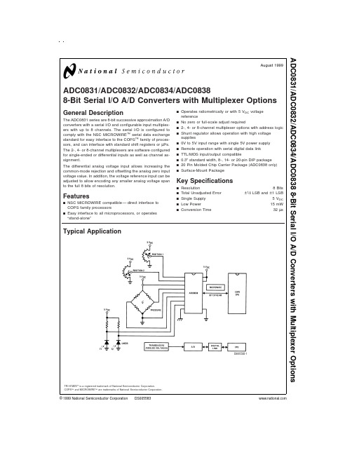

ADC0831数模转换器(0-5V数码显示)第一部分:实物及管脚定义1、CS:片选2、正输入端3、Vref:负输入端4、GND:地5、参考电压输入端6、DO:串行数据输出端7、CLK:时钟输入脚 8、VCC:电源产品种类ADC0831(模数转换器)转换器数量1ADC 输入端数量1分辨率8 bit输入类型Voltage(电压)接口类型Serial(串行输出)电压参考5 V电源电压(最大值)6.3 V电源电压(最小值)4.5 V最大功率耗散0.8 W最大工作温度+ 70 C输入电压5 V第二部分:时序图第三部分:仿真图第四部分:C语言程序/*程序效果:数码管显示0.00-5.00U电压,调节电位器,得到ADC0831的2脚电压值。
注:测量时先把电位器调节到中间,也就是2.5U,但切记所测的引脚的电压值不能超过5U,否则会烧坏ADC0831芯片和单片机。
*/#include<reg52.h>#include<intrins.h>#define uchar unsigned char#define uint unsigned intsbit CS=P1^0;sbit CLK=P1^1;sbit DO=P1^2;uchar codetab[]={0x3f,0x06,0x5b,0x4f,0x66,0x6d,0x7d,0x07,0x7f,0x6f,//共阴数码0-90xbf,0x86,0xdb,0xcf,0xe6,0xed,0xfd,0x87,0xff,0xef,//共阴带小数0-90x40,0x3e,0x00}; //"-"、"U"、数码管全灭uchar code du[]={0xfe,0xfd,0xfb,0xf7};//动态扫描时控制各个数码管亮与灭uint huancun[]={0,0,0,0}; //数据缓存void delay();//延时函数void display(); //数码管显示函数uchar Read_ADC0831(); //读取ADC0831转换出的数据,通过串行通信输出//************************************************//void main(){uint i,date;while(1){i++;if(i==100){i=0;date=Read_ADC0831()*100;//乘以100是为了保留两位小数,错误的写法date=Read_ADC0831()*100/51//处理数据时要注意:各变量的数据类型要一致!date=date/51; //使数码管显示的数值与电压保//当ADC转换5V电压时,对应255即date=255*100/51=500huancun[0]=date/100; //取数据百位huancun[0]+=10; //数据百位带小数点,所以要取带小数的codehuancun[1]=date%100/10; //数据十位,即为小数点第一位huancun[2]=date%10; //数据个位,即为小数点第二位huancun[3]=21; //电压符号“U”}display();}}//************************************************//void delay(){uchar i;for(i=0;i<180;i++);}//*********************************************// void display(){uchar i;for(i=0;i<4;i++){P3=du[i];P2=tab[huancun[i]];delay();}}//********************************************// uchar Read_ADC0831()//根据时序图写出的模拟数据输出{uchar i,temp; DO=1;_nop_();_nop_();CS=0;_nop_();_nop_();CLK=0;_nop_();_nop_();CLK=1;_nop_();_nop_();CLK=0;_nop_();_nop_();CLK=1;_nop_();_nop_();CLK=0;_nop_();_nop_();for(i=0;i<8;i++) {CLK=1;_nop_();_nop_();temp<<=1;if(DO){temp++;}CLK=0;_nop_();_nop_();}CS=1;_nop_();_nop_(); return(temp); }。

![adc0808中文资料[整理版]](https://img.taocdn.com/s1/m/c09ee7f85ff7ba0d4a7302768e9951e79b896975.png)
11.2.4 典型的集成ADC芯片为了满足多种需要,目前国内外各半导体器件生产厂家设计并生产出了多种多样的ADC芯片。
仅美国AD公司的ADC产品就有几十个系列、近百种型号之多。
从性能上讲,它们有的精度高、速度快,有的则价格低廉。
从功能上讲,有的不仅具有A/D转换的基本功能,还包括内部放大器和三态输出锁存器;有的甚至还包括多路开关、采样保持器等,已发展为一个单片的小型数据采集系统。
尽管ADC芯片的品种、型号很多,其内部功能强弱、转换速度快慢、转换精度高低有很大差别,但从用户最关心的外特性看,无论哪种芯片,都必不可少地要包括以下四种基本信号引脚端:模拟信号输入端(单极性或双极性);数字量输出端(并行或串行);转换启动信号输入端;转换结束信号输出端。
除此之外,各种不同型号的芯片可能还会有一些其他各不相同的控制信号端。
选用ADC芯片时,除了必须考虑各种技术要求外,通常还需了解芯片以下两方面的特性。
(1)数字输出的方式是否有可控三态输出。
有可控三态输出的ADC芯片允许输出线与微机系统的数据总线直接相连,并在转换结束后利用读数信号RD选通三态门,将转换结果送上总线。
没有可控三态输出(包括内部根本没有输出三态门和虽有三态门、但外部不可控两种情况)的ADC芯片则不允许数据输出线与系统的数据总线直接相连,而必须通过I/O接口与MPU交换信息。
(2)启动转换的控制方式是脉冲控制式还是电平控制式。
对脉冲启动转换的ADC芯片,只要在其启动转换引脚上施加一个宽度符合芯片要求的脉冲信号,就能启动转换并自动完成。
一般能和MPU配套使用的芯片,MPU的I/O写脉冲都能满足ADC芯片对启动脉冲的要求。
对电平启动转换的ADC芯片,在转换过程中启动信号必须保持规定的电平不变,否则,如中途撤消规定的电平,就会停止转换而可能得到错误的结果。
为此,必须用D 触发器或可编程并行I/O 接口芯片的某一位来锁存这个电平,或用单稳等电路来对启动信号进行定时变换。

#include<reg52.h>#include<stdio.h>#include<string.h>#include<math.h>#define uchar unsigned char#define uint unsigned intsbit pianxuan=P3^3; 片选sbit shuchu=P3^1; 数据线sbit clk=P3^2; 时钟线code unsigned char seg7code[10]={ 0xc0,0xf9,0xa4,0xb0,0x99,0x92,0x82,0xf8,0x80,0x90}; //显示段码数码管字跟:Delay(unsigned int tc) //延时程序{while( tc != 0 ) //如果tc 为0 则终止延时{unsigned int i; //局部正整数变量ifor(i=0; i<50; i++); //执行400 次将耗时1毫秒tc--; //tc计数减一}}uchar M=0;uchar shuzi=0;delayms(){uchar j=0;for(j=0; j<100; j++);}void Led(int date) //显示函数{P1=P1&0xf7; //P2.7 输出低电平,选通千位数P0=seg7code[date/1000]; //取出千位数,查表,输出。
Delay(5); //延时P1=P1|0x0f; //销隐P1=P1&0xfb; //P2.6 输出低电平,选通百位数P0=seg7code[date%1000/100]; //取出百位数,查表,输出。
Delay(5); //延时P1=P1|0x0f; //销隐P1=P1&0xfd; //P2.5 输出低电平,选通十位数P0=seg7code[date%100/10]; //取出十位数,查表,输出。
ADC08031/ADC08034/ADC080388-Bit High-Speed Serial I/O A/D Converters withMultiplexer Options,Voltage Reference,and Track/Hold FunctionGeneral DescriptionThe ADC08031/ADC08032/ADC08034/ADC08038are 8-bit successive approximation A/D converters with serial I/O and configurable input multiplexers with up to 8channels.The serial I/O is configured to comply with the NSC MICROW-IRE ™serial data exchange standard for easy interface to the COPS ™family of controllers,and can easily interface with standard shift registers or microprocessors.The ADC08034and ADC08038provide a 2.6V band-gap de-rived reference.For devices offering guaranteed voltage ref-erence performance over temperature see ADC08131,ADC08134and ADC08138.A track/hold function allows the analog voltage at the positive input to vary during the actual A/D conversion.The analog inputs can be configured to operate in various combinations of single-ended,differential,or pseudo-differential modes.In addition,input voltage spans as small as 1V can be accommodated.Applicationsn Digitizing automotive sensors n Process control monitoringn Remote sensing in noisy environments nInstrumentationn Test systemsn Embedded diagnosticsFeaturesn Serial digital data link requires few I/O pins n Analog input track/hold functionn 2-,4-,or 8-channel input multiplexer options with address logicn 0V to 5V analog input range with single 5V power supplyn No zero or full scale adjustment required n TTL/CMOS input/output compatible n On chip 2.6V band-gap referencen 0.3"standard width 8-,14-,or 20-pin DIP package n 14-,20-pin small-outline packagesKey Specificationsn Resolution 8bits n Conversion time (f C =1MHz)8µs (max)n Power dissipation 20mW (max)n Single supply 5V DC (±5%)n Total unadjusted error ±1⁄2LSB and ±1LSBnNo missing codes over temperatureOrdering InformationIndustrial (−40˚C ≤T A ≤+85˚C)Package ADC08031CINN08E ADC08031CIWM,ADC08034CIWM M14B ADC08038CIWMM20BTRI-STATE ®is a registered trademark of National Semiconductor Corporation.COPS ™microcontrollers and MICROWIRE ™are trademarks of National Semiconductor Corporation.June 1999ADC08031/ADC08034/ADC080388-Bit High-Speed Serial I/O A/D Converters with Multiplexer Options,Voltage Reference,and Track/Hold Function©1999National Semiconductor Corporation Connection DiagramsADC08038DS010555-2ADC08034DS010555-3ADC08031Dual-In-Line Package DS010555-5ADC08031Small Outline Package 2Absolute Maximum Ratings(Notes1,3) If Military/Aerospace specified devices are required, please contact the National Semiconductor Sales Office/ Distributors for availability and specifications.Supply Voltage(V CC) 6.5V Voltage at Inputs and Outputs−0.3V to V CC+0.3V Input Current at Any Pin(Note4)±5mA Package Input Current(Note4)±20mA Power Dissipation at T A=25˚C(Note5)800mW ESD Susceptibility(Note6)1500V Soldering InformationN Package(10sec.)SO Package:Vapor Phase(60sec.) Infrared(15sec.)(Note7)260˚C215˚C220˚CStorage Temperature−65˚C to+150˚COperating Ratings(Notes2,3)Temperature Range T MIN≤T A≤T MAXADC08031CIN,−40˚C≤T A≤+85˚CADC08031CIWM,ADC08034CIWM,ADC08038CIWMSupply Voltage(V CC) 4.5V DC to6.3V DCElectrical CharacteristicsThe following specifications apply for V CC=V REF=+5V DC,and f CLK=1MHz unless otherwise specified.Boldface limits apply for T A=T J=T MIN to T MAX;all other limits T A=T J=25˚C.Symbol Parameter ConditionsADC08031,ADC08034andADC08038Units(Limits) Typical(Note8)Limits(Note9)CONVERTER AND MULTIPLEXER CHARACTERISTICSTotal Unadjusted Error(Note10)BIN,BIWM±1⁄2LSB(max)CIN,CIWM±1LSB(max)Differential8Bits(min)LinearityR REF Reference Input Resistance 3.5kΩ1.3kΩ(min)6.0kΩ(max)V IN Analog Input Voltage(Note11)(V CC+0.05)V(max)(GND−0.05)V(min) DC Common-Mode Error±1⁄4LSB(max)Power Supply Sensitivity V CC=5V±5%,±1⁄4LSB(max)V REF=4.75VOn Channel Leakage On Channel=5V,0.2µA(max)Current(Note12)Off Channel=0V1On Channel=0V,−0.2µA(max)Off Channel=5V−1Off Channel Leakage On Channel=5V,−0.2µA(max)Current(Note12)Off Channel=0V−1On Channel=0V,0.2µA(max)Off Channel=5V1DIGITAL AND DC CHARACTERISTICSV IN(1)Logical“1”Input Voltage V CC=5.25V 2.0V(min)V IN(0)Logical“0”Input Voltage V CC=4.75V0.8V(max)I IN(1)Logical“1”Input Current V IN=5.0V1µA(max)I IN(0)Logical“0”Input Current V IN=0V−1µA(max)V OUT(1)Logical“1”Output Voltage V CC=4.75V:I OUT=−360µA 2.4V(min)I OUT=−10µA 4.5V(min)3Electrical Characteristics(Continued)The following specifications apply for V CC=V REF=+5V DC,and f CLK=1MHz unless otherwise specified.Boldface limits apply for T A=T J=T MIN to T MAX;all other limits T A=T J=25˚C.Symbol Parameter ConditionsADC08031,ADC08034andADC08038Units(Limits) Typical(Note8)Limits(Note9)DIGITAL AND DC CHARACTERISTICSV OUT(0)Logical“0”Output Voltage V CC=4.75V0.4V(max)I OUT=1.6mAI OUT TRI-STATE®Output Current V OUT=0V−3.0µA(max)V OUT=5V 3.0µA(max)I SOURCE Output Source Current V OUT=0V−6.5mA(min)I SINK Output Sink Current V OUT=V CC8.0mA(min)I CC Supply CurrentADC08031,ADC08034,andADC08038CS=HIGH 3.0mA(max) REFERENCE CHARACTERISTICSV REF OUT Nominal Reference Output V REF OUT OptionAvailable Only on 2.6VADC08034andADC08038Electrical CharacteristicsThe following specifications apply for V CC=V REF=+5V DC,and t r=t f=20ns unless otherwise specified.Boldface limits apply for T A=T J=T MIN to T MAX;all other limits T A=T J=25˚C.Symbol Parameter Conditions Typical Limits Units(Note8)(Note9)(Limits) f CLK Clock Frequency10kHz(min)1MHz(max) Clock Duty Cycle40%(min)(Note13)60%(max) T C Conversion Time(Not Including f CLK=1MHz81/f CLK(max) MUX Addressing Time)8µs(max) t CA Acquisition Time1⁄21/f CLK(max) t SELECT CLK High while CS is High50nst SET-UP CS Falling Edge or Data Input25ns(min) Valid to CLK Rising Edget HOLD Data Input Valid after CLK20ns(min) Rising Edget pd1,t pd0CLK Falling Edge to Output C L=100pF:Data Valid(Note14)Data MSB First250ns(max)Data LSB First200ns(max) t1H,t0H TRI-STATE Delay from Rising Edge C L=10pF,R L=10kΩ50ns of CS to Data Output and SARS Hi-Z(see TRI-STATE Test Circuits)C L=100pF,R L=2kΩ180ns(max) C IN Capacitance of Logic Inputs5pFC OUT Capacitance of Logic Outputs5pFNote1:Absolute Maximum Ratings indicate limits beyond which damage to the device may occur.Note2:Operating Ratings indicate conditions for which the device is functional.These ratings do not guarantee specific performance limits.For guaranteed speci-fications and test conditions,see the Electrical Characteristics.The guaranteed specifications apply only for the test conditions listed.Some performance character-istics may degrade when the device is not operated under the listed test conditions.Note3:All voltages are measured with respect to AGND=DGND=0V DC,unless otherwise specified.4Electrical Characteristics(Continued)Note4:When the input voltage V IN at any pin exceeds the power supplies(V IN<(AGND or DGND)or V IN>V CC)the current at that pin should be limited to5mA. The20mA maximum package input current rating limits the number of pins that can safely exceed the power supplies with an input current of5mA to four pins. Note5:The maximum power dissipation must be derated at elevated temperatures and is dictated by T JMAX,θJA and the ambient temperature,T A.The maximum allowable power dissipation at any temperature is P D=(T JMAX−T A)/θJA or the number given in the Absolute Maximum Ratings,whichever is lower.For devices with suffixes CIN and CIWM T JMAX=125˚C.The typical thermal resistances(θJA)of these parts when board mounted follow:ADC08031CIN120˚C/W,ADC08031CIWM 140˚C/W,ADC08034CIWM140˚C/W,ADC08038CIWM suffixes91˚C/W.Note6:Human body model,100pF capacitor discharged through a1.5kΩresistor.Note7:See AN450“Surface Mounting Methods and Their Effect on Product Reliability”or Linear Data Book section“Surface Mount”for other methods of soldering surface mount devices.Note8:Typicals are at T J=25˚C and represent the most likely parametric norm.Note9:Guaranteed to National’s AOQL(Average Outgoing Quality Level).Note10:Total unadjusted error includes offset,full-scale,linearity,multiplexer.Note11:For V IN(−)≥V IN(+)the digital code will be00000000.Two on-chip diodes are tied to each analog input(see Block Diagram)which will forward-conduct for analog input voltages one diode drop below ground or one diode drop greater than V CC supply.During testing at low V CC levels(e.g.,4.5V),high level analog inputs (e.g.,5V)can cause an input diode to conduct,especially at elevated temperatures,which will cause errors for analog inputs near full-scale.The spec allows50mV forward bias of either diode;this means that as long as the analog V IN does not exceed the supply voltage by more than50mV,the output code will be correct.Ex-ceeding this range on an unselected channel will corrupt the reading of a selected channel.Achievement of an absolute0V DC to5V DC input voltage range will there-fore require a minimum supply voltage of4.950V DC over temperature variations,initial tolerance and loading.Note12:Channel leakage current is measured after a single-ended channel is selected and the clock is turned off.For off channel leakage current the following two cases are considered:one,with the selected channel tied high(5V DC)and the remaining seven off channels tied low(0V DC),total current flow through the off chan-nels is measured;two,with the selected channel tied low and the off channels tied high,total current flow through the off channels is again measured.The two cases considered for determining on channel leakage current are the same except total current flow through the selected channel is measured.Note13:A40%to60%duty cycle range insures proper operation at all clock frequencies.In the case that an available clock has a duty cycle outside of these limits the minimum time the clock is high or low must be at least450ns.The maximum time the clock can be high or low is100µs.Note14:Since data,MSB first,is the output of the comparator used in the successive approximation loop,an additional delay is built in(see Block Diagram)to allow for comparator response time.Typical Performance CharacteristicsLinearity Error vsReference VoltageDS010555-32Linearity Error vsTemperatureDS010555-33Linearity Error vsClock FrequencyDS010555-34Power Supply Current vs TemperatureDS010555-35Output Current vsTemperatureDS010555-36Power Supply Currentvs Clock FrequencyDS010555-37 5Leakage Current Test CircuitTRI-STATE Test Circuits and WaveformsTiming DiagramsDS010555-7t 1HDS010555-38DS010555-39t 0HDS010555-40DS010555-41Data Input Timingstandards ADC0831/2/4/8. 6Timing Diagrams(Continued)Data Output TimingDS010555-11ADC08031Start Conversion TimingDS010555-12ADC08031TimingDS010555-13*LSB first output not available on ADC08031.LSB information is maintained for remainder of clock periods until CS goes high.7Timing Diagrams(Continued)ADC08034TimingDS010555-15 8Timing Diagrams(Continued)A D C 08038T i m i n gD S 010555-16*M a k e s u r e c l o c k e d g e #18c l o c k s i n t h e L S B b e f o r e S E i s t a k e n l o w9ADC08038Functional Block Diagram Functional Description1.0MULTIPLEXER ADDRESSINGThe design of these converters utilizes a comparator struc-ture with built-in sample-and-hold which provides for a differ-ential analog input to be converted by a successive-approximation routine.The actual voltage converted is always the difference be-tween an assigned“+”input terminal and a“−”input terminal. The polarity of each input terminal of the pair indicates which line the converter expects to be the most positive.If the as-signed“+”input voltage is less than the“−”input voltage the converter responds with an all zeros output code.A unique input multiplexing scheme has been utilized to pro-vide multiple analog channels with software-configurable single-ended,differential,or pseudo-differential(which will convert the difference between the voltage at any analog in-put and a common terminal)operation.The analog signal conditioning required in transducer-based data acquisition systems is significantly simplified with this type of input flex-ibility.One converter package can now handle ground refer-enced inputs and true differential inputs as well as signals with some arbitrary reference voltage.A particular input configuration is assigned during the MUX addressing sequence,prior to the start of a conversion.The MUX address selects which of the analog inputs are to beDS1555-17*Someofthesefunctions/pinsarenotavailablewithotheroptions.FortheADC834,the“SEL1”Flip-Flopisbypassed.10Functional Description(Continued) enabled and whether this input is single-ended or differential. Differential inputs are restricted to adjacent channel pairs. For example,channel0and channel1may be selected as a differential pair but channel0or1cannot act differentially with any other channel.In addition to selecting differential mode the polarity may also be selected.Channel0may be selected as the positive input and channel1as the negative input or vice versa.This programmability is best illustrated by the MUX addressing codes shown in the following tables for the various product options.The MUX address is shifted into the converter via the DI line. Because the ADC08031contains only one differential input channel with a fixed polarity assignment,it does not require addressing.The common input line(COM)on the ADC08038can be used as a pseudo-differential input.In this mode the voltage on this pin is treated as the“−”input for any of the other input channels.This voltage does not have to be analog ground;it can be any reference potential which is common to all of the inputs.This feature is most useful in single-supply applica-tions where the analog circuity may be biased up to a poten-tial other than ground and the output signals are all referred to this potential.TABLE1.Multiplexer/Package OptionsPartNumberNumber of AnalogChannelsNumber ofPackagePinsSingle-Ended DifferentialADC08031118ADC08032218ADC080344214ADC080388420TABLE2.MUX Addressing:ADC08038Single-Ended MUX ModeMUX Address Analog Single-Ended Channel#START SGL/ODD/SELECT01234567COM DIF SIGN1011000+−11001+−11010+−11011+−11100+−11101+−11110+−11111+−TABLE3.MUX Addressing:ADC08038Differential MUX ModeMUX Address Analog Differential Channel-Pair#START SGL/ODD/SELECT0123 DIF SIGN1001234567 10000+−10001+−10010+−10011+−10100−+10101−+10110−+10111−+11Functional Description(Continued)TABLE4.MUX Addressing:ADC08034Single-Ended MUX ModeMUX Address Channel#START SGL/ODD/SELECT0123DIF SIGN11100+1101+1110+1111+ COM is internally tied to AGNDSince the input configuration is under software control,it can be modified as required before each conversion.A channel can be treated as a single-ended,ground referenced input for one conversion;then it can be reconfigured as part of a differential channel for another conversion.Figure1illus-trates the input flexibility which can be achieved.The analog input voltages for each channel can range from 50mV below ground to50mV above V CC(typically5V)with-out degrading conversion accuracy.2.0THE DIGITAL INTERFACEA most important characteristic of these converters is their serial data link with the controlling ing a serial communication format offers two very significant system im-provements;it allows many functions to be included in a small package and it can eliminate the transmission of low level analog signals by locating the converter right at the analog sensor;transmitting highly noise immune digital data back to the host processor.To understand the operation of these converters it is best to refer to the Timing Diagrams and Functional Block Diagram and to follow a complete conversion sequence.For clarity a separate timing diagram is shown for each device.1.A conversion is initiated by pulling the CS(chip select)line low.This line must be held low for the entire conver-sion.The converter is now waiting for a start bit and its MUX assignment word.2.On each rising edge of the clock the status of the data in(DI)line is clocked into the MUX address shift register.The start bit is the first logic“1”that appears on this line (all leading zeros are ignored).Following the start bit the converter expects the next2to4bits to be the MUX as-signment word.3.When the start bit has been shifted into the start locationof the MUX register,the input channel has been as-signed and a conversion is about to begin.An interval of 1⁄2clock period(where nothing happens)is automatically inserted to allow the selected MUX channel to settle.The SARS line goes high at this time to signal that a con-version is now in progress and the DI line is disabled(it no longer accepts data).4.The data out(DO)line now comes out of TRI-STATEand provides a leading zero for this one clock period of MUX settling time.5.During the conversion the output of the SAR comparatorindicates whether the analog input is greater than(high) or less than(low)a series of successive voltages gener-ated internally from a ratioed capacitor array(first5bits) and a resistor ladder(last3bits).After each comparison the comparator’s output is shipped to the DO line on the falling edge of CLK.This data is the result of the conver-sion being shifted out(with the MSB first)and can be read by the processor immediately.6.After8clock periods the conversion is completed.TheSARS line returns low to indicate this1⁄2clock cycle later.7.The stored data in the successive approximation registeris loaded into an internal shift register.If the programmer prefers the data can be provided in an LSB first format [this makes use of the shift enable(SE)control line].On the ADC08038the SE line is brought out and if held high the value of the LSB remains valid on the DO line.When SE is forced low the data is clocked out LSB first.On de-vices which do not include the SE control line,the data, LSB first,is automatically shifted out the DO line after the MSB first data stream.The DO line then goes low and stays low until CS is returned high.The ADC08031 is an exception in that its data is only output in MSB first format.8.All internal registers are cleared when the CS line is highand the t SELECT requirement is met.See Data Input Tim-ing under Timing Diagrams.If another conversion is de-sired CS must make a high to low transition followed by address information.The DI and DO lines can be tied together and controlled through a bidirectional processor I/O bit with one wire.This is possible because the DI input is only“looked-at”during the MUX addressing interval while the DO line is still in a high impedance state.12Functional Description(Continued)3.0REFERENCE CONSIDERATIONSThe voltage applied to the reference input on these convert-ers,V REF IN,defines the voltage span of the analog input (the difference between V IN(MAX)and V IN(MIN)over which the 256possible output codes apply.The devices can be used either in ratiometric applications or in systems requiring ab-solute accuracy.The reference pin must be connected to a voltage source capable of driving the reference input resis-tance which can be as low as 1.3k Ω.This pin is the top of a resistor divider string and capacitor array used for the suc-cessive approximation conversion.In a ratiometric system the analog input voltage is propor-tional to the voltage used for the A/D reference.This voltage is typically the system power supply,so the V REF IN pin can be tied to V CC .This technique relaxes the stability require-ments of the system reference as the analog input and A/D reference move together maintaining the same output code for a given input condition.For absolute accuracy,where the analog input varies be-tween very specific voltage limits,the reference pin can be biased with a time and temperature stable voltage source.For the ADC08034and the ADC08038a band-gap derived reference voltage of 2.6V (Note 8)is tied to V REF OUT.This can be tied back to V REF IN.Bypassing V REF OUT with a 100µF capacitor is recommended.The LM385and LM336reference diodes are good low current devices to use with these converters.The maximum value of the reference is limited to the V CC supply voltage.The minimum value,however,can be quite small (see Typical Performance Characteristics)to allow di-rect conversions of transducer outputs providing less than a 5V output span.Particular care must be taken with regard to noise pickup,circuit layout and system error voltage sources when operating with a reduced span due to the increased sensitivity of the converter (1LSB equals V REF/256).8Single-EndedDS010555-488Pseudo-DifferentialDS010555-494Differential DS010555-50Mixed ModeDS010555-51FIGURE 1.Analog Input Multiplexer Options for the ADC0803813Functional Description(Continued)4.0THE ANALOG INPUTSThe most important feature of these converters is that they can be located right at the analog signal source and through just a few wires can communicate with a controlling proces-sor with a highly noise immune serial bit stream.This in itself greatly minimizes circuitry to maintain analog signal accu-racy which otherwise is most susceptible to noise pickup.However,a few words are in order with regard to the analog inputs should the input be noisy to begin with or possibly riding on a large common-mode voltage.The differential input of these converters actually reduces the effects of common-mode input noise,a signal common to both selected “+”and “−”inputs for a conversion (60Hz is most typical).The time interval between sampling the “+”in-put and then the “−”input is 1⁄2of a clock period.The change in the common-mode voltage during this short time interval can cause conversion errors.For a sinusoidal common-mode signal this error is:where f CM is the frequency of the common-mode signal,V PEAK is its peak voltage value and f CLK is the A/D clock frequency.For a 60Hz common-mode signal to generate a 1⁄4LSB error (≈5mV)with the converter running at 250kHz,its peak value would have to be 6.63V which would be larger than allowed as it exceeds the maximum analog input limits.Source resistance limitation is important with regard to the DC leakage currents of the input multiplexer.Bypass capaci-tors should not be used if the source resistance is greater than 1k Ω.The worst-case leakage current of ±1µA over tem-perature will create a 1mV input error with a 1k Ωsource re-sistance.An op amp RC active low pass filter can provide both impedance buffering and noise filtering should a high impedance signal source be required.5.0OPTIONAL ADJUSTMENTS5.1Zero ErrorThe zero of the A/D does not require adjustment.If the mini-mum analog input voltage value,V IN(MIN),is not ground a zero offset can be done.The converter can be made to out-put 00000000digital code for this minimum input voltage by biasing any V IN (−)input at this V IN(MIN)value.This utilizes the differential mode operation of the A/D.The zero error of the A/D converter relates to the location of the first riser of the transfer function and can be measured by grounding the V IN (−)input and applying a small magnitude positive voltage to the V IN (+)input.Zero error is the differ-ence between the actual DC input voltage which is neces-sary to just cause an output digital code transition from 00000000to 00000001and the ideal 1⁄2LSB value (1⁄2LSB =9.8mV for V REF =5.000V DC ).5.2Full ScaleThe full-scale adjustment can be made by applying a differ-ential input voltage which is 11⁄2LSB down from the desired analog full-scale voltage range and then adjusting the mag-nitude of the V REF IN input for a digital output code which is just changing from 11111110to 11111111.5.3Adjusting for an Arbitrary Analog Input Voltage RangeIf the analog zero voltage of the A/D is shifted away from ground (for example,to accommodate an analog input signal which does not go to ground),this new zero reference should be properly adjusted first.A V IN (+)voltage which equals this desired zero reference plus 1⁄2LSB (where the LSB is calculated for the desired analog span,using 1LSB =analog span/256)is applied to selected “+”input and the zero reference voltage at the corresponding “−”input should then be adjusted to just obtain the 00HEX to 01HEX code tran-sition.The full-scale adjustment should be made [with the proper V IN (−)voltage applied]by forcing a voltage to the V IN (+)in-put which is given by:DS010555-52a)RatiometricDS010555-53b)Absolute with a Reduced SpanFIGURE 2.Reference Examples 14Functional Description(Continued)where:V MAX =the high end of the analog input rangeandV MIN =the low end (the offset zero)of the analog range.(Both are ground referenced.)The V REF IN (or V CC )voltage is then adjusted to provide a code change from FE HEX to FF HEX .This completes the ad-justment procedure.ApplicationsA “Stand-Alone”Hook-Up for ADC08038EvaluationDS010555-44*Pinouts shown for ADC08038.For all other products tie to pin functions as shown.15Applications(Continued)Low-Cost Remote Temperature SensorDS010555-45Digitizing a Current FlowDS010555-22 16Applications(Continued)Operating with Ratiometric TransducersDS010555-23*V IN(−)=0.15V CC15%of V CC≤V XDR≤85%of V CCSpan Adjust;0V≤V IN≤3VDS010555-4617Applications(Continued)Zero-Shift and Span Adjust:2V ≤V IN ≤5VDS010555-47Protecting the Input DS010555-25Diodes are 1N914High Accuracy ComparatorsDS010555-26DO =all 1s if +V IN >−V IN DO =all 0s if +V IN <−V IN 18Applications(Continued)Digital Load CellDS010555-27•Uses one more wire than load cell itself•Two mini-DIPs could be mounted inside load cell for digital output transducer•Electronic offset and gain trims relax mechanical specs for gauge factor and offset•Low level cell output is converted immediately for high noise immunity19Applications(Continued)4mA-20mA Current Loop ConverterDS010555-28•All power supplied by loop•1500V isolation at output20Applications(Continued)Isolated Data ConverterDS010555-29•No power required remotely•1500V isolation21Physical Dimensions inches(millimeters)unless otherwise notedOrder Number ADC08031CIWM or ADC08034CIWMNS Package Number M14B22Physical Dimensions inches(millimeters)unless otherwise noted(Continued)Order Number ADC08038CIWMNS Package Number M20BOrder Number ADC08031CINNS Package Number N08E23。
ADCV08318Bit Serial I/O Low Voltage Low Power ADC with Auto Shutdown in a SOT PackageGeneral DescriptionThe ADCV0831is a low voltage 8-bit successive approxima-tion A/D converter with serial I/O.The I/O is a 3-wire serial in-terface compatible with NSC’s MICROWIRE ™&Motorola’s SPI standards.It easily interfaces with standard shift regis-ters or microprocessors.Low voltage and auto shutdown features make the ADCV0831ideal for portable battery operated electronic de-vices.The main benefits are most apparent in small portable electronic devices.The tiny A/D converter can be placed anywhere on the board.Applicationsn Digitizing automotive sensors n Process control monitoringn Remote sensing in noisy environments n Instrumentation n Test systemsnEmbedded diagnosticsFeaturesn Tiny 6-pin SOT 23packagen Serial digital data link requires few I/O pins n Auto Shutdownn0V to 3V analog input range with single 3V power supplyn TTL/CMOS input/output compatibleKey Specifications(For 3V supply,typical,unless otherwise noted.)n Resolution:8bitsn Conversion time (f C =700kHz):16µs n Low power dissipation:720µW n Single supply: 2.7V to 5V DCn Linearity error:±1.5LSB over temperature n No missing codes over temperature n Shutdown supply current 10nAOrdering InformationTemperature Range (0˚C ≤T j ≤+70˚C)Package Supplied As ADCV0831M6MA06A 1k Units Tape and Reel ADCV0831M6XMA06A3k Units Tape and ReelConnection DiagramTRI-STATE ®is a registered trademark of National Semiconductor Corporation.COPS ™microcontrollers and MICROWIRE ™are trademarks of National Semiconductor Corporation.ADCV0831DS100104-1February 2000ADCV08318Bit Serial I/O Low Voltage Low Power ADC with Auto Shutdown in a SOT Package©2000National Semiconductor Corporation Absolute Maximum Ratings (Notes 1,3)If Military/Aerospace specified devices are required,please contact the National Semiconductor Sales Office/Distributors for availability and specifications.Supply Voltage (V CC )5.5VVoltage at Inputs and Outputs −0.3V to V CC +0.3VInput Current at Any Pin (Note 4)±5mA Package Input Current (Note 4)±20mAPower Dissipation at T A =25˚C (Note 5)470mW ESD Susceptibility (Note 6)2000VSoldering Temperature (Note 7)Convection Infrared (15sec.)215˚C Wave Soldering (4sec.)(Note 7)260˚CStorage Temperature−65˚C to +150˚CThermal Resistance (θJA )265˚C/WOperating Ratings (Notes 2,3)Temperature Range 0˚C ≤T j ≤70˚C Supply Voltage (V CC )2.7V DC to 5VElectrical CharacteristicsThe following specifications apply for V CC =3V DC ,and f CLK =500kHz unless otherwise specified.Boldface limits apply for T A =T J =T MIN to T MAX ;all other limits T A =T J =25˚C.SymbolParameterConditionsTypical (Note 8)Limits (Note 9)Units Integral Linearity Error ±0.6±1.5LSB (max)Offset Error ±0.1±1.5LSB (max)Full Scale Error ±0.3±1.5LSB (max)Resolution8Bits (min)V IN Analog Input Voltage (V CC +0.05)V (max)(GND −0.05)V (min)V IN(1)Logical “1”Input Voltage V CC =3V 2.0V (min)V IN(0)Logical “0”Input Voltage V CC =3V 0.8V (max)I IN(1)Logical “1”Input Current V IN =3V 0.011µA (max)I IN(0)Logical “0”Input Current V IN =0V 0.01−1µA (max)V OUT(1)Logical “1”Output Voltage I out =-360µA 2.8 2.4V (min)V OUT(0)Logical “0”Output Voltage I out =1.6mA 0.240.4V (max)I OUT TRI-STATE ®Output Current V OUT =0V 0.01 3.0µA (max)I SOURCE Output Source Current V OUT =0V 2.6 1.0mA (min)I SINK Output Sink Current V OUT =3V 7.4 3.0mA (min)I CCSupply CurrentCS =HIGH 0.0130µA (max)CS =LOW200400µA (max)AC Electrical CharacteristicsThe following specifications apply for V CC =+3V DC ,and t r =t f =20ns unless otherwise specified.Boldface limits apply for T A =T J =T MIN to T MAX ;all other limits T A =T J =25˚C.Symbol ParameterConditionsTypical Limits Units(Note 8)(Note 9)f CLK Clock Frequency700kHz (max)10kHz (min)t SET-UPCS failing edge to CLK rising edge 25ns Clock Duty Cycle40%(min)60%(max)T C Conversion Time11Clock Periods t pd CLK Falling Edge to Data ValidLow to High C L =100pF142250ns (max)High to Low70200t 1H ,t 0HCS Rising Edge to Data Output TRI-STATE C L =100pF,R L =2k Ω75250ns (max)(see TRI-STATE Test Circuits)C L =100pF,R L =10k Ω50A D C V 0831 2AC Electrical Characteristics(Continued)The following specifications apply for V CC=+3V DC,and t r=t f=20ns unless otherwise specified.Boldface limits apply for T A=T J=T MIN to T MAX;all other limits T A=T J=25˚C.Symbol Parameter Conditions Typical Limits Units(Note8)(Note9)C IN Capacitance of Logic Inputs5pFC OUT Capacitance of Logic Outputs5pF Note1:Absolute Maximum Ratings indicate limits beyond which damage to the device may occur.Note2:Operating Ratings indicate conditions for which the device is functional.These ratings do not guarantee specific performance limits.For guaranteed speci-fications and test conditions,see the Electrical Characteristics.The guaranteed specifications apply only for the test conditions listed.Some performance character-istics may degrade when the device is not operated under the listed test conditions.Note3:All voltages are measured with respect to GND=0V DC,unless otherwise specified.Note4:When the input voltage V IN at any pin exceeds the power supplies(V IN<GND or V IN>V CC)the current at that pin should be limited to5mA.The20mA maximum package input current rating limits the number of pins that can safely exceed the power supplies with an input current of5mA to four pins.Note5:The maximum power dissipation must be derated at elevated temperatures and is dictated by T JMAX,θJA and the ambient temperature,T A.The maximum allowable power dissipation at any temperature is P D=(T JMAX−T A)/θJA or the number given in the Absolute Maximum Ratings,whichever is lower.Note6:Human body model,100pF capacitor discharged through a1.5kΩresistor.Note7:See AN450“Surface Mounting Methods and Their Effect on Product Reliability”or Linear Data Book section“Surface Mount”for other methods of soldering surface mount devices.Note8:Typicals are at T J=25˚C and represent the most likely parametric norm.Note9:Guaranteed to National’s AOQL(Average Outgoing Quality Level).Typical Performance CharacteristicsThe following specifications apply for V CC=3V,unless otherwise specifiedIntegral Linearity Error vsSupply VoltageDS100104-62Linearity Error vsTemperatureDS100104-56Linearity Error vsClock FrequencyDS100104-55Power Supply Currentvs TemperatureDS100104-57Output Current vsTemperatureDS100104-58Power Supply Currentvs Clock FrequencyDS100104-61ADCV08313TRI-STATE Test Circuits and WaveformsTiming DiagramsDS100104-8Data Output TimingDS100104-10Start Conversion TimingDS100104-11A D C V 0831 4ADCV0831 Timing Diagrams(Continued)Timing Array DS100104-125Functional DescriptionThe design of this converter utilizes a comparator structure with built-in sample-and-hold which provides for V IN to be converted by a successive approximation routine.The analog input voltage can range from 50mV below ground to 50mV above V CC without degrading conversion accuracy.The ADCV0831is intended to work with a CPU which strobes data on the clock’s rising edge.The ADCV0831strobes data on the clock’s falling edge so that the data out-put is stable when the CPU reads it in.When the Chip Select pin is high,the output is TRI-STATE and the ADCV0831is in shutdown mode and draws less than 30µA of current.During shutdown the digital logic draws no current at CMOS logic levels,and the analog cir-cuitry is turned off.When the Chip Select pin goes low,all the analog circuitry turns on,and the conversion process begins.1.0THE DIGITAL INTERFACEThe most important characteristic of this converter is the se-rial data link with the controlling ing a serial communication format offers three very significant system improvements.It allows many functions to be included in a small package,it can eliminate the transmission of low level analog signals by locating the converter right at the analog sensor,and can transmit highly noise immune digital data back to the host processor.To understand the operation of this converter it is best to re-fer to the Timing Diagrams and to follow a complete conver-sion sequence.1.A conversion is initiated by pulling the CS (chip select)line low.This line must be held low for the entire conver-sion.2.During the conversion the output of the SAR comparatorindicates whether the analog input is greater than (high)or less than (low)a series of successive voltages in a re-sistor ladder (last 8bits).After each comparison the comparator’s output is shifted to the DO line on the fall-ing edge of CLK.This data is the result of the conversion being shifted out (with the MSB first)and can be read by the processor immediately.3.After 11clock periods the conversion is completed.4.All internal registers are cleared when the CS line ishigh.See Data Input Timing under Timing Diagrams.If another conversion is desired CS must make a high to low transition.2.0REFERENCE CONSIDERATIONSIn a ratiometric system,the analog input voltage is propor-tional to the voltage used for the A/D reference.This voltage is the system power supply.This technique relaxes the sta-bility requirements of the system reference as the analog in-put and A/D reference move together maintaining the same output code for a given input condition.Since there is no separate reference and analog supply pins,the analog side is very sensitive.The PC layout of the ADCV0831is very critical.The ADCV0831should be used with an analog ground plane and single-point grounding techniques.The Gnd pin should be tied directly to the ground plane.One supply bypass capacitor (0.1µF)is recom-mended to decouple all the digital signals on the supplies.The lead length of the capacitor should be as short as pos-sible.3.0THE ANALOG INPUTThe most important feature of this converter is that it can be located right at the analog signal source through just a few wires.It can communicate with a processor with a highly noise immune serial bit stream.This greatly minimizes cir-cuitry to maintain analog signal accuracy which otherwise is most susceptible to noise pickup.However,a few words are in order with regard to the analog inputs should the input be noisy to begin with or possibly riding on a large common-mode voltage.The input has a sample and hold,therefore a capacitor (0.01µF)is needed at the input pin in order to swamp out any feedthrough signal coming from the sample and hold cir-cuitry.The input capacitor lead length is not as critical as the supply decoupling capacitor,as long as the capacitor is large enough to swamp out any sample and hold feedthrough.Source resistance limitation is important with regard to the DC leakage currents of the input multiplexer.Bypass capaci-tors should not be used if the source resistance is greater than 1k Ω.The worst-case leakage current of ±1µA over tem-perature will create a 1mV input error with a 1k Ωsource re-sistance.An op-amp RC active low pass filter can provide both impedance buffering and noise filtering should a high impedance signal source be required.DS100104-59Recommended Power Supply BypassingA D C V 0831 6ApplicationsThe ADCV0831is ideal for applications operating with ratiometric transducers.The ADCV0831can measure the signal produced by the transducer and produce a corresponding code to the microprocessor.The microprocessor can then control the system pro-ducing the signal.The ADCV0831can be used in low-cost remote temperature sensor system.For a temperature sensor,the LM60is an excellent companion to the ADCV0831,since it can operate off 3V supply.The LM60linear scale factor is 6.25mV/˚C.Therefore,the ADCV0831can digitize a couple of degrees change in temperature and provide the output to the microprocessor,which in turn can adjust the system environment.For higher accuracy,a low-offset op-amp can be used to gain up the LM60output.Operating with Ratiometric TransducersDS100104-63Low-Cost Remote Temperature SensorDS100104-60ADCV08317Applications(Continued)When the input of the ADCV0831is driven by an op-amp operating at a supply voltage greater than 5V,it is a good idea to protect the input of the ADCV0831from exceeding the supply voltage.Two diodes can be added to the input one to supply and one to the ground pin.Note:Diodes are IN914This circuit utilizes the LM385reference to detect the power supply voltage level.When the supply voltage is 3V,the LSB =3/256=11.7mV.Since the LM385reference sets the input to 1.2V.The output code is 102.As the supply voltage decreases,the LSB decreases and the output code increases.When the supply voltage reaches 2.7V,the LSB =10.5mV.The input voltage is still at 1.2V,and the output code is 114.If the supply voltage increases,the LSB increases and the output code decreases.When the supply voltage reaches 3.3V,the LSB =12.9mV and the output code is 93.Protecting the inputDS100104-64Power Supply Level DetectionDS100104-65A D C V 0831 8Physical Dimensionsinches (millimeters)unless otherwise notedLIFE SUPPORT POLICYNATIONAL’S PRODUCTS ARE NOT AUTHORIZED FOR USE AS CRITICAL COMPONENTS IN LIFE SUPPORT DEVICES OR SYSTEMS WITHOUT THE EXPRESS WRITTEN APPROVAL OF THE PRESIDENT AND GENERAL COUNSEL OF NATIONAL SEMICONDUCTOR CORPORATION.As used herein:1.Life support devices or systems are devices or systems which,(a)are intended for surgical implant into the body,or (b)support or sustain life,and whose failure to perform when properly used in accordance with instructions for use provided in the labeling,can be reasonably expected to result in a significant injury to the user.2.A critical component is any component of a life support device or system whose failure to perform can be reasonably expected to cause the failure of the life support device or system,or to affect its safety or effectiveness.National Semiconductor Corporation AmericasTel:1-800-272-9959Fax:1-800-737-7018Email:support@National Semiconductor EuropeFax:+49(0)180-5308586Email:europe.support@Deutsch Tel:+49(0)6995086208English Tel:+44(0)8702402171Français Tel:+33(0)141918790National Semiconductor Asia Pacific Customer Response Group Tel:65-2544466Fax:65-2504466Email:ap.support@National Semiconductor Japan Ltd.Tel:81-3-5639-7560Fax:81-3-5639-7507Order Number ADCV0831M6X,ADCV0831M6NS Package Number MA06AADCV08318Bit Serial I/O Low Voltage Low Power ADC with Auto Shutdown in a SOT PackageNational does not assume any responsibility for use of any circuitry described,no circuit patent licenses are implied and National reserves the right at any time without notice to change said circuitry and specifications.。