
BS-3, 规格书,Datasheet 资料
- 格式:pdf
- 大小:98.75 KB
- 文档页数:1

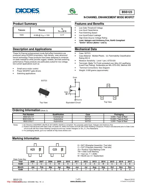
N-CHANNEL ENHANCEMENT MODE MOSFETProduct SummaryV (BR)DSS R DS(ON) I DT A = 25°C 100V6.0Ω @ V GS = 10V0.17Description and Applications These N-Channel enhancement mode field effect transistors are produced using DIODES proprietary, high density, uses advanced trench technology.These products have been designed to minimize on-state resistance while provide rugged, reliable, and fast switchingperformance.These products are particularly suited for low voltage,low current applications such as• Small servo motor control• Power MOSFET gate drivers• Switching applicationsFeatures and Benefits• Low Gate Threshold Voltage • Low Input Capacitance • Fast Switching Speed• Low Input/Output Leakage• High Drain-Source Voltage Rating• Lead, Halogen and Antimony Free, RoHS Compliant • "Green" Device (Notes 1 and 2)Mechanical Data• Case: SOT23 • Case Material: Molded Plastic. UL Flammability Classification Rating 94V-0 • Moisture Sensitivity: Level 1 per J-STD-020• Terminals: Matte Tin Finish annealed over Alloy 42 Leadframe (Lead Free Plating). Solderable per MIL-STD-202, Method 208 • Terminal Connections: See Diagram • Weight: 0.008 grams (approximate)Ordering Information (Note 3)Part Number Qualification Case PackagingBSS123-7-FCommercial SOT23 3,000 / Tape & Reel BSS123Q-13 Automotive SOT23 10,000 / Tape & Reel BSS123Q-7Automotive SOT23 3,000 / Tape & ReelNotes: 1. EU Directive 2002/95/EC (RoHS) & 2011/65/EU (RoHS 2) compliant. No purposely added lead. Halogen and Antimony free.2. Product manufactured with Date Code V9 (week 33, 2008) and newer are built with Green Molding Compound. Product manufactured prior to Date Code V9 are built with Non-Green Molding Compound and may contain Halogens or Sb 2 O 3 Fire Retardants.3. For packaging details, go to our website at Marking InformationDate Code KeyYear 2006 2007 2008 2009 2010 2011 2012 2013 2014 2015 2016 2017Code T U V WX Y Z A B C D EMonth Jan Feb Mar Apr May Jun Jul Aug Sep Oct Nov DecCode 1 2 3 4 5 6 7 8 9 O N DEquivalent Circuit Top View Top View SOT23 GateK = SAT (Shanghai Assembly / Test site) C = CAT (Chengdu Assembly / Test site) 23 = Product Type Marking Code YM = Date Code Marking Y = Year (ex: T = 2006)M = Month (ex: 9 = September)K23Y MC23Y MMaximum Ratings @T A = 25°C unless otherwise specifiedCharacteristicSymbol Value UnitDrain-Source Voltage V DSS 100 V Gate-Source VoltageContinuous V GSS ±20 V Continuous Drain Current (Note 4) V GS = 10V Continuous I D 170mAPulsedI DM680Thermal Characteristics @T A = 25°C unless otherwise specifiedCharacteristic Symbol Max UnitPower Dissipation (Note 4) P D300 mW Thermal Resistance, Junction to Ambient @T A = 25°C (Note 4) R θJA417 °C/W Operating and Storage Temperature Range T J , T STG -55 to +150 °CElectrical Characteristics @ T A = 25°C unless otherwise statedCharacteristicSymbol Min Typ Max Unit Test ConditionOFF CHARACTERISTICS (Note 5) Drain-Source Breakdown Voltage BV DSS 100 - - V V GS = 0V, I D = 250μAZero Gate Voltage Drain Current I DSS - - 0.1 μA V DS = 100V, V GS = 0V - - 10 nA V DS = 20V, V GS = 0V Gate-Source Leakage , Forward I GSSF - - 50 nA V GS = 20V, V DS = 0VON CHARACTERISTICS (Note 5) Gate Threshold VoltageV GS(th)0.8 1.4 2.0 V V DS = V GS , I D = 1mAStatic Drain-Source On-Resistance R DS (ON)- - 6.0 Ω V GS = 10V, I D = 0.17A- - 10 V GS = 4.5V, I D = 0.17AForward Transfer Admittance g FS 80 370 - mS V DS =10V, I D = 0.17A, f = 1.0KHzDiode Forward VoltageV SD - 0.84 1.3 V V GS = 0V, I S = 0.34A, DYNAMIC CHARACTERISTICS Input Capacitance C iss- 29 60 pF V DS = 25V, V GS = 0V, f = 1.0MHzOutput CapacitanceC oss - 10 15 Reverse Transfer CapacitanceC rss - 2 6 SWITCHING CHARACTERISTICS Turn-On Delay Time t D(on) - - 8 ns V GS = 10V, V DD = 30V,I D = 0.28A, R GEN = 50Ω Turn-On Rise Time t r - - 8 ns Turn-Off Delay Time t D(off) - - 13 nsTurn-Off Fall Timet f--16 nsNotes: 4. Part mounted on FR-4 board with recommended pad layout, which can be found on our website at .5. Short duration pulse test used to minimize self-heating effect.I , D R A I N -S O U R C E C U R R E N T (A )D V , DRAIN-SOURCE VOLTAGE (V)Fig. 1 On-Region Characteristics DSR , N O R M A L I Z E D D R A I N -S O U R C E O N -R E S I S T A N C ED S (O N )I , DRAIN-SOURCE CURRENT (A)Fig. 2 On-Resistance Variation with Gate Voltageand Drain-Source Current D0.8V N O R M A L I Z E D T H R E S H O L D V O L T A G EG S (t h ),T , JUNCTION TEMPERATURE (ºC)Fig. 3 Gate Threshold Variation with T emperature J 0.4R N O R M A L I Z E D O N -R E S IS T A N C ED S (O N ),T , JUNCTION TEMPERATURE (ºC)Fig. 4 On-Resistance Variation with Temperature J 0.6C , C A P A C I T A N C E (p F )V , DRAIN-SOURCE VOLTAGE (V)Fig. 5 Typical CapacitanceDSPackage Outline DimensionsSuggested Pad LayoutSOT23Dim Min Max Typ A 0.37 0.51 0.40 B 1.20 1.40 1.30 C 2.30 2.50 2.40 D 0.89 1.03 0.915 F 0.45 0.60 0.535 G 1.78 2.05 1.83 H 2.80 3.00 2.90 J 0.0130.10 0.05 K 0.903 1.10 1.00 K1 - - 0.400 L 0.45 0.61 0.55 M 0.0850.18 0.11α0° 8° - All Dimensions in mmDimensions Value (in mm)Z 2.9 X 0.8 Y 0.9C2.0 E1.35 X EYCZIMPORTANT NOTICEDIODES INCORPORATED MAKES NO WARRANTY OF ANY KIND, EXPRESS OR IMPLIED, WITH REGARDS TO THIS DOCUMENT, INCLUDING, BUT NOT LIMITED TO, THE IMPLIED WARRANTIES OF MERCHANTABILITY AND FITNESS FOR A PARTICULAR PURPOSE (AND THEIR EQUIVALENTS UNDER THE LAWS OF ANY JURISDICTION).Diodes Incorporated and its subsidiaries reserve the right to make modifications, enhancements, improvements, corrections or other changes without further notice to this document and any product described herein. Diodes Incorporated does not assume any liability arising out of the application or use of this document or any product described herein; neither does Diodes Incorporated convey any license under its patent or trademark rights, nor the rights of others. Any Customer or user of this document or products described herein in such applications shall assume all risks of such use and will agree to hold Diodes Incorporated and all the companies whose products are represented on Diodes Incorporated website, harmless against all damages.Diodes Incorporated does not warrant or accept any liability whatsoever in respect of any products purchased through unauthorized sales channel. Should Customers purchase or use Diodes Incorporated products for any unintended or unauthorized application, Customers shall indemnify and hold Diodes Incorporated and its representatives harmless against all claims, damages, expenses, and attorney fees arising out of, directly or indirectly, any claim of personal injury or death associated with such unintended or unauthorized application.Products described herein may be covered by one or more United States, international or foreign patents pending. Product names and markings noted herein may also be covered by one or more United States, international or foreign trademarks.LIFE SUPPORTDiodes Incorporated products are specifically not authorized for use as critical components in life support devices or systems without the express written approval of the Chief Executive Officer of Diodes Incorporated. As used herein:A. Life support devices or systems are devices or systems which:1. are intended to implant into the body, or2. support or sustain life and whose failure to perform when properly used in accordance with instructions for use provided in thelabeling can be reasonably expected to result in significant injury to the user.B. A critical component is any component in a life support device or system whose failure to perform can be reasonably expected to cause thefailure of the life support device or to affect its safety or effectiveness.Customers represent that they have all necessary expertise in the safety and regulatory ramifications of their life support devices or systems, and acknowledge and agree that they are solely responsible for all legal, regulatory and safety-related requirements concerning their products and any use of Diodes Incorporated products in such safety-critical, life support devices or systems, notwithstanding any devices- or systems-related information or support that may be provided by Diodes Incorporated. Further, Customers must fully indemnify Diodes Incorporated and its representatives against any damages arising out of the use of Diodes Incorporated products in such safety-critical, life support devices or systems.Copyright © 2012, Diodes Incorporated分销商库存信息:DIODESBSS123-7-F BSS123-7。

Specifi cations are subject to change without notice.Customers should verify actual device performance in their specifi c applications.*RoHS Directive 2002/95/EC Jan. 27, 2003 including annex and RoHS Recast 2011/65/EU June 8, 2011.Stop Strength..............................................................................................................................................................................45 N-cm (64 oz.-in.) minimum Mechanical Angle ...........................................................................................................................................................................................3600 ° +10 °, -0 °Torque (Starting & Running) ................................................................................................................................0.35 N-cm (0.5 oz.-in.) maximum (unsealed) 1.1 N-cm (1.5 oz.-in.) maximum (sealed) Mounting ..............................................................................................................................................................................55-80 N-cm (5-7 lb.-in.) (plastic) 90-113 N-cm (8-10 in.-lb.) (metal)Shaft Runout......................................................................................................................................................................................0.13 mm (0.005 in.) teral Runout ...................................................................................................................................................................................0.20 mm (0.008 in.) T.I.R.Shaft End Play ...................................................................................................................................................................................0.25 mm (0.010 in.) T.I.R.Shaft Radial Play ...............................................................................................................................................................................0.13 mm (0.005 in.) T.I.R.Pilot Diameter Runout .......................................................................................................................................................................0.08 mm (0.003 in.) T.I.R.Backlash ............................................................................................................................................................................................................1.0 ° maximum Weight ........................................................................................................................................................................................................Approximately 19 G Terminals ................................................................................................................................................................................................Solder lugs or PC pins Soldering ConditionManual Soldering...........................................................96.5Sn/3.0Ag/0.5Cu solid wire or no-clean rosin cored wire; 370 °C (700 °F) max. for 3 seconds Wave Soldering ...................................................................................96.5Sn/3.0Ag/0.5Cu solder with no-clean fl ux; 260 °C (500 °F) max. for 5 seconds Wash processes .......................................................................................................................................................................................Not recommended Marking .....................................Manufacturer’s name and part number, resistance value and tolerance, linearity tolerance, wiring diagram, and date code.Ganging (Multiple Section Potentiometers) ......................................................................................................................................................1 cup maximum Hardware ............................................................................................................One lockwasher and one mounting nut is shipped with each potentiometer.NOTE: For Anti-rotation pin add 91 after confi guration dash number. Example: -2 becomes -291 to add AR pin.1At room ambient: +25 °C nominal and 50 % relative humidity nominal, except as noted. 2Consult manufacturer for complete specifi cation details for resistances below 1k ohms.BOLDFACE LISTINGS ARE IN STOCK AND READILY AVAILABLETHROUGH DISTRIBUTION. FOR OTHER OPTIONS CONSULT FACTORY.ROHS IDENTIFIER: L = COMPLIANTRecommended Part Numbers(Printed Circuit)(Solder Lug)(Solder Lug)Resistance (Ω)Resolution (%)3590P-2-102L 3590S-2-102L 3590S-1-102L 1,000.0293590P-2-202L 3590S-2-202L 3590S-1-202L 2,000.0233590P-2-502L 3590S-2-502L 3590S-1-502L 5,000.0253590P-2-103L 3590S-2-103L 3590S-1-103L 10,000.0203590P-2-203L 3590S-2-203L 3590S-1-203L 20,000.0193590P-2-503L 3590S-2-503L 3590S-1-503L 50,000.0133590P-2-104L3590S-2-104L3590S-1-104L100,000.009*Ro H S C O MP L I A N T/Panel Thickness Dimensions(For Bushing Mount Only)1.60 +.08/-.03(.063 +.003/-.001)DIA.ANTI-ROTATION PINAnti-rotation pin hole is shown at six o'clockposition for reference only. The actual location isdetermined by the customer's application. Referto the front view of the potentiometer to see thelocation of the optional A/R pin.Panel thickness and hole diameters arerecommended for best fit. However, customersmay adjust the dimensions to suit their specificapplication.Product DimensionsSpecifi cations are subject to change without notice.Customers should verify actual device performance in their specifi c applications.REV. 06/12 MOUNTING SURFACE-2, -4, -6, -8 Confi gurations-1, -3, -5, -7 Confi gurationsRecommended PCB LayoutHOLE DIAMETER5.08(.200)5.08(.200)6.99(.275)SchematicTOLERANCES: EXCEPT WHERE NOTED.508 .127DECIMALS: .XX ±(.02),.XXX ±(.005)FRACTIONS: ±1/64MMDIMENSIONS:(IN.)Shaft & Bushing Confi gurations(Bushing - DxL, Shaft - D):(-1) Plastic Bushing (3/8 ” x 5/16 ”)and Shaft (.2480 + .001, - .002)(-2) Metal Bushing (3/8 ” x 5/16 ”)and Shaft (.2497 + .0000, - .0009)(-3) Sealed, Plastic Bushing (3/8 ” x 5/16 ”)and Shaft (.2480 + .001, - .002)(-4) Sealed, Metal Bushing (3/8 ” x 5/16 ”)and Shaft (.2497 + .0000, - .0009)(-5) Metric, Plastic Bushing (9 mm x 7.94 mm)and Shaft (6 mm + 0, - .076 mm)(-6) Metric, Metal Bushing (9 mm x 7.94 mm)and Shaft (6 mm + 0, - .023 mm)(-7) Metric, Sealed, Plastic Bushing (9 mm x7.94 mm) and Shaft (6 mm + 0, - .076 mm)(-8) Metric, Sealed, Metal Bushing (9 mm x7.94 mm) and Shaft (6 mm + 0, - .023 mm)Terminal Styles“P” Terminal Style“S” Terminal Style/分销商库存信息:BOURNS3590S-2-502L3590S-2-102L3590S-2-103L 3590S-2-203L3590S-1-502L3590S-2-104L 3590S-1-203L3590S-2-501L3590S-2-202L 3590S-1-503L3590S-2-503L3590S-1-104L 3590S-291-102L3590S-291-203L3590S-291-502L 3590S-1-201L3590S-1-501L3590S-2-101L 3590S-2-201L3590P-1-102L3590P-1-103L 3590P-1-201L3590P-1-502L3590S-1-102L 3590S-1-103L3590S-2-252L3590P-291-501L 3590P-2-102L3590P-2-201L3590P-2-203L 3590P-2-502L3590S-1-202L3590S-6-102L 3590S-6-201L3590S-6-202L3590S-6-203L 3590S-6-501L3590P-1-104L3590S-6-502L 3590S-4-102L3590S-4-103L3590S-4-202L 3590S-4-203L3590S-4-502L3590S-8-102L 3590S-8-103L3590S-8-202L3590P-2-104L 3590P-4-103L3590P-4-202L3590S-6-503L 3590S-6-104L3590S-4-104L3590P-4-503L 3590P-4-104L3590S-2-5023590S-1-102 3590S-1-1033590S-1-1043590S-1-203 3590S-1-5023590S-1-5033590S-2-102 3590S-2-1033590S-2-1043590S-2-203 3590S-2-5033590S-1-2023590S-2-202 3590S-2-501。

Electric cylinder units EPCS-BSThis product is also available as a modular mechanical systemElectric cylinder EPCC2d Internet: /catalogue/...Subject to change – 2023/08Electric cylinder units EPCS-BSKey featuresAt a glancePlug and work with the Simplified Motion SeriesThe simplicity of pneumatics is now combined for the first time with the advantag-es of electric automation thanks to the Simplified Motion Series.These integrated drives are the perfect solution for all users who are looking for an electric alternative for very simple movement and positioning tasks between two mechanical end positions, but don't want the commissioning process for tra -ditional electric drive systems that can often be quite complex. There is no need for any software since operation is simply based on the "plug and work" principle. Digital I/O (DIO) and IO-Link ® are always automatically in -cluded – a product with two types of control as standard.IntegratedEasyStandardisedConnectedThe integrated electronics in the drive are at the heart of the Simplified Motion Series.For commissioning, simply set all rele-vant parameters directly on the drive:• Speed and force• Reference end position and cush -ioning• Manual operationElectrical connection via M12 plug design• Power (4-pin): power supply for the motor• Logic (8-pin): control signal, sensor signal and power for the integrated electronicsUse of extended functions possible via IO-Link ®:• Remote configuration of motion pa-rameters• Copy and backup function for trans -ferring parameters• Read function for extended p rocess parameters• Freely definable intermediate posi-tion• Firmware updateThe functions of the Simplified Motion Series Basic profile for movement between two end positions: Extended motion profile for simplified press-fitting and clamping functions: with v v• • Proximity switches are required in order to implement any intermediate positions.• With the intermediate position that can be freely configured via IO-Link ®, movements can be stopped at any point between the end positions, without the need for proximity switches or external stops32023/08 – Subject to changed Internet: /catalogue/...Electric cylinder units EPCS-BSKey featuresAt a glance• Without external servo drive: all the necessary electronic components are com -bined in the integrated drive• Two control options integrated as standard: digital I/O and IO-Link ®• Complete solution for simple movements between mechanical end positions • Simplified commissioning: all parameters can be manually set directly on the drive• No special expertise required for commissioning• End-position feedback similar to that of a conventional proximity switch is inte-grated as standard• Very high-quality ball screw with low internal friction• Ideal for precise and fast movement in sorting, distribution or clamping appli -cationsThe products in the Simplified Motion Series Electric cylinder unit EPCE Electric cylinder unit EPCSElectric cylinder unit with parallelmotor mounting EPCSMini slide unit EGSS-BS-KFMini slide unit with parallel motor mounting EGSS-BS-KFSpindle axis unit ELGS-BS-KFSpindle axis unit with parallel motor mounting ELGS-BS-KFToothed belt axis unit ELGS-TB-KF Toothed belt axis unit ELGE Rotary drive unit ERMSModular and flexible with motor, motor mounting kit and servo driveThis product is also available as a modular mechanical system as electric cylinder EPCC-BS:When it comes down to flexibility and adaptability, the compact dimensions and different combinations are ideal for making optimal use of the installation space.• Compact: optimum ratio of installation space to working space • Unique: "one-size-down" mounting system• Modular: individual combinations with motor, motor mounting kit and servo drive • Flexible: wide range of mounting options for optimum machine integration4d Internet: /catalogue/...Subject to change – 2023/08Electric cylinder units EPCS-BSKey featuresCombination matrix between axis ELGC-TB/ELGS-TB, ELGC-BS/ELGS-BS, mini slide EGSC-BS/EGSS-BS, electric cylinder EPCC-BS/EPCS-BS and guide axis ELFC Mounting options with profile mounting and with angle kitWith profile mounting EAHF-L2-…-P-D…With angle kit EHAA-D-L2-…-APElectric cylinder units EPCS-BS Key featuresCombination matrix between axis ELGC/ELGS-TB, ELGC/ELGS-BS, mini slides EGSC/EGSS-BS, electric cylinder EPCC/EPCS-BS and guide axis ELFCMounting options with adapter kit or direct fasteningWith adapter kit EHAA-D-L2With direct mounting• Mounting option: base axis with the same size assembly axis• Mounting option: base axis with height compensation for one-size-down as-sembly axis• When motors are mounted using parallel kits, this may lead to interfering con-• Mounting option: base axis with the same size assembly axis5 2023/08 – Subject to change d Internet: /catalogue/...6d Internet: /catalogue/...Subject to change – 2023/08Electric cylinder units EPCS-BSKey featuresTypical handling systemsThe axes ELGC can be combined into very space-saving handling systems that are suitable for assembly systems, test and inspection systems, small parts handling, the electronics industry and desktop applications where compact dimensions are essential. Combining the very compact linear axes ELGC, mini slides EGSC and electric cyl-inder EPCC offers an optimum ratio of installation space to working space. These feature a common system approach and platform architecture and the connections are largely adapterless.Cantilever systemPlanar surface gantry3-dimensional gantryElectric cylinder units EPCS-BS Type codes7 2023/08 – Subject to change d Internet: /catalogue/...8d Internet: /catalogue/...Subject to change – 2023/08Electric cylinder units EPCS-BSPeripherals overviewCable outlet direction Standard[D] Underneath [L] Left [R] RightControl elements[1] Pushbutton actuators for parameterisation and controlOn topaaElectric cylinder units EPCS-BS Peripherals overview1)Proximity switches are optional and only required in order to sense any intermediate positions.92023/08 – Subject to change d Internet: /catalogue/...10d Internet: /catalogue/...Subject to change – 2023/08Electric cylinder units EPCS-BSDatasheet-N- Size 32 ... 60-T-Stroke length 25 ... 500 mm1) At the drive shaft 2) When new3) Adjustable in increments of 10%4)Unchangeable parameterDatasheetMaterialsSectional view1234Pin allocationPower supply Logic interface Plug PlugDatasheetMaximum permissible loads on the piston rodIf there are two or more forces and torques si -multaneously acting on the piston rod, the following equations must be satisfied:F 1/M 1 = dynamic value F 2/M 2 = maximum valueff vv =|FF yy 1|FF yy2+|FF zz1|FF zz2+|MM yy1|MM yy2+|MM zz1|MM zz2≤1 |MMMMMMMM | ≤ MMMMMMMM mmmmmmmm mmmm|FFFF FFFF | ≤ FFFFFFFF mmmmmmmm mmmm Maximum permissible lateral forces Fy max and Fz max on the piston rod as a function of projection AEPCSA [mm]F y m a x , F z m a x [N ]100200300400500600110100EPCS-BS-32EPCS-BS-45EPCS-BS-60H- -NoteEngineering software Electric Motion Sizinga /x/electric-motion-sizingPiston rod deflection f 2 as a function of projection A and lateral force FA [mm]f [m m ]1002003004005006000123456ffff 1=FFFF 1FFFF 2∙ffff 2f 1 = Piston rod deflection caused by lateral force [mm]F 1 = Lateral force [N]F 2 = Standardised lateral force [N] (constant force from graph)f 2= Piston rod deflection caused by lateral force [N] (reading from graph)Example : Electric cylinder EPCS-32-50-8P with a lateral force of 7 N F 1 = 7 N and F standard = 3.5 NValue read from graph for EPCS-32 and projection = 50 mm f 2 = 1 mmCalculation of deflection caused by lateral force:ffff 1=FFFF 1FFFF 2∙ffff 2=3 NNNN 1,5 NNNN∙1 mmmmmmmm =2 mmmmmmmmEPCS-BS-32 (F 2 = 3.5 N)EPCS-BS-45 (F 2 = 4.0 N)EPCS-BS-60 (F 2 = 8.0 N)DatasheetCalculating the mean feed force F xm with the electric cylinder EPCSThe peak feed force value must not exceed the maximum feed force within a movement cycle. The peak value is generally achieved in vertical operation during the acceleration phase of the upwards stroke. If the maximum feed force is exceeded, this can increase wear and thus shorten the service life of the ball screw. The maximum speed must likewise not be exceed-ed:F xš F xmax andv xš v xmaxCalculating the mean feed force F xm (to DIN 69051-4)During operation, the continuous feed force may be briefly exceeded up to the maximum feed force. The continuous feedforce must, however, be adhered to when averaged over a movement cycle:F xmš F xcontinuousFFFF xxxx xxxx=��FFFF xxxx3∙vvvv xxxx vvvv xxxx xxxx∙qqqq1003=FFFF xxxx xxxx=�FFFF xxxx13∙vvvv xxxx1vvvv xxxx xxxx∙qqqq1100+FFFF xxxx23∙vvvv xxxx2vvvv xxxx xxxx∙qqqq2100+FFFF xxxx33∙vvvv xxxx3vvvv xxxx xxxx∙qqqq3100 3+⋯Mean feed speed (to DIN 69051-4)vv xxxx=∑vv xx∙qq100=vv xx1∙qq1100+vv xx2∙qq2100+vv xx3∙qq3100+⋯F x Feed forceF xm Mean feed forceF xmax.Max. feed forceF xcontinuous C ontinuous feed forceq Timev x Feed speedv xm Mean feed speedv xmax.Max. Feed speed F x [N]q [100%]F xmaxF xmF x3F x2F x1q1q2q3v x [mm/s]q [100%]v xmav xmv x3v x2v x1q1q2q3Mean feed force F xm as a function of running performance L, with an operating coefficient f B of 1.0 at room temperature Size 32Size 45EPCS-45L [km]F [N ]200040006000800010000075150225300375450525600EPCS-BS-32-3P EPCS-BS-32-8PEPCS-BS-45-3P EPCS-BS-45-10PSize 60EPCS-60L [km]F [N ]20004000600080001000002004006008001000EPCS-BS-60-5P EPCS-BS-60-12P1) This refers to stress caused by impact, temperature, contamination, shock and vibrations that affect the cylinder or piston rod.H- -NoteThe specifications for running performance are based on experimentally deter-mined and theoretically calculated data (at room temperature). The running per-formance that can be achieved in practice can deviate considerably from the specified curves under different parameters.LLLL 1=LLLL ffff BBBB3L 1 Actual service life L Target service life(d graphs)f B Operating coefficientDatasheetSizing example Application data:• Payload: 25 kg• Mounting position: horizontal • Motor mounting position: axial • Stroke: 150 mm• Max. permissible positioning time: 2 s (one direction)Step 1: Selecting the smallest possible size from the table a page 10Step 2: Selecting the max. speed level v for payload mStep 3: Reading off the min. positioning time t for stroke lEPCS-45-10P v m [k g ]EPCS-45-10P vt [s ]HorizontalVerticall = 50 mm l = 100 mm l = 150 mm l = 200 mm l = 250 mm l = 300 mma Max. speed level for the payload: level 7a Min. positioning time for 150 mm at level 7: 1 sResultThe application can be implemented using EPCS-BS-45-150-10P . A minimum positioning time (one direction) of 1 s is achieved. Longer positioning times can be select-ed at any time using a lower speed level.Mass m as a function of speed level v With axial kit EPCS-BS-32-3PEPCS-BS-32-8PEPCS-32-3P v m [k g ]123456789100510152025EPCS-32-8Pvm [k g ]123456789100510152025Horizontal VerticalEPCS-BS-45-3PEPCS-BS-45-10PEPCS-45-3Pv m [k g ]123456789100102030405060EPCS-45-10Pvm [k g ]12345678910010********Horizontal VerticalEPCS-BS-60-5PEPCS-BS-60-12PEPCS-60-5Pv m [k g ]12345678910020406080100120EPCS-60-12Pvm [k g ]123456789100102030405060Horizontal VerticalH- -NoteThe lines represent the maximum values. The lower speed levels can be set at any time.DatasheetPositioning time t as a function of speed level v and stroke l With axial kit EPCS-BS-32-3PEPCS-BS-32-8PEPCS-32-3P v t [s ]123456789100510********EPCS-32-8Pvt [s ]12345678910024681012l = 50 mm l = 100 mm l = 150 mm l = 200 mml = 50 mm l = 100 mm l = 150 mm l = 200 mmEPCS-BS-45-3P EPCS-BS-45-10PEPCS-45-3Pv t [s ]12345678910010********EPCS-45-10Pv t [s ]12345678910024********l = 50 mm l = 100 mm l = 150 mm l = 200 mm l = 250 mm l = 300 mm l = 50 mm l = 100 mm l = 150 mm l = 200 mm l = 250 mm l = 300 mmElectric cylinder units EPCS-BSDatasheetPositioning time t as a function of speed level v and stroke l With axial kit EPCS-BS-60-5PEPCS-BS-60-12PEPCS-60-5P v t [s ]123456789100102030405060EPCS-60-12Pvt [s ]123456789100510152025l = 50 mm l = 100 mm l = 150 mm l = 200 mm l = 250 mm l = 300 mm l = 350 mm l = 400 mm l = 500 mm l = 50 mm l = 100 mm l = 150 mm l = 200 mm l = 250 mm l = 300 mm l = 350 mm l = 400 mm l = 500 mmElectric cylinder units EPCS-BSDatasheetMass m as a function of speed level v With parallel kit EPCS-BS-32-3PEPCS-BS-32-8PEPCS-32-3P v m [k g ]12345678910510152025EPCS-32-8Pvm [k g ]123456789100510152025Horizontal VerticalEPCS-BS-45-3PEPCS-BS-45-10PEPCS-45-3Pv m [k g ]123456789100102030405060EPCS-45-10Pvm [k g ]12345678910010********Horizontal VerticalEPCS-BS-60-5PEPCS-BS-60-12PEPCS-60-5Pv m [k g ]12345678910020406080100120EPCS-60-12Pvm [k g ]123456789100102030405060Horizontal VerticalH- -NoteThe lines represent the maximum values. The lower speed levels can be set at any time.Electric cylinder units EPCS-BSDatasheetPositioning time t as a function of speed level v and stroke l With parallel kit EPCS-BS-32-3PEPCS-BS-32-8PEPCS-32-3P v t [s ]123456789100510********EPCS-32-8Pvt [s ]12345678910024681012l = 50 mm l = 100 mm l = 150 mm l = 200 mml = 50 mm l = 100 mm l = 150 mm l = 200 mmEPCS-BS-45-3P EPCS-BS-45-10PEPCS-45-3Pv t [s ]12345678910010********EPCS-45-10Pv t [s ]12345678910024********l = 50 mm l = 100 mm l = 150 mm l = 200 mm l = 250 mm l = 300 mm l = 50 mm l = 100 mm l = 150 mm l = 200 mm l = 250 mm l = 300 mmElectric cylinder units EPCS-BSDatasheetPositioning time t as a function of speed level v and stroke l With parallel kit EPCS-BS-60-5PEPCS-BS-60-12PEPCS-60-5P v t [s ]123456789100102030405060EPCS-60-12Pvt [s ]123456789100510152025l = 50 mm l = 100 mm l = 150 mm l = 200 mm l = 250 mm l = 300 mm l = 350 mm l = 400 mm l = 500 mm l = 50 mm l = 100 mm l = 150 mm l = 200 mm l = 250 mm l = 300 mm l = 350 mm l = 400 mm l = 500 mmFeed force F as a function of force level F1EPCS-BSF1F [N ]123456789101002003004005006007008009001000EPCS-BS-32-3P/-8P EPCS-BS-45-3P EPCS-BS-45-10P EPCS-BS-60-5P EPCS-BS-60-12PElectric cylinder units EPCS-BS DatasheetElectric cylinder units EPCS-BS DatasheetElectric cylinder units EPCS-BS DatasheetElectric cylinder units EPCS-BS DatasheetElectric cylinder units EPCS-BS Ordering data – Modular product system[2]Not with motor mounting position PR[3]Not with motor mounting position PT[4]Not with motor mounting position PL[5]Not in combination with cable outlet direction R[6]Not in combination with cable outlet direction L[7]Not in combination with cable outlet direction standard[8]Not in combination with cable outlet direction DElectric cylinder units EPCS-BSAccessoriesProfile mounting EAHF-L2-...-P-S• For mounting the cylinder on the side of the profile Material:Anodised wrought aluminium alloyRoHS-compliantProfile mounting EAHF-L2-...-P Material:Anodised wrought aluminium alloy RoHS-compliant • For mounting the cylinder on the side of the profile.The profile mounting can be attached to the mounting surface using the drilled hole in the centreAccessoriesFlange mounting EAHH Material:Galvanised steel RoHS-compliant1)Corrosion resistance class CRC 1 to Festo standard FN 940070 Low corrosion stress. Dry internal application or transport and storage protection. Also applies to parts behind covers, in the non-visible interior area, or parts that are covered in the application (e.g. drive trunnions).Adapter kit EAHA Material:RoHS-compliant1)Corrosion resistance class CRC 1 to Festo standard FN 940070Low corrosion stress. Dry internal application or transport and storage protection. Also applies to parts behind covers, in the non-visible interior area, or parts that are covered in the application (e.g. drive trunnions).AccessoriesSwivel mounting EAHS Material:Galvanised steel RoHS-compliant1)Corrosion resistance class CRC 1 to Festo standard FN 940070 Low corrosion stress. Dry internal application or transport and storage protection. Also applies to parts behind covers, in the non-visible interior area, or parts that are covered in the application (e.g. drive trunnions).Trunnion support LNZG Material:Trunnion support: Anodised aluminiumPlain bearing: Plastic Free of copper and PTFE RoHS-compliant1)Corrosion resistance class CRC 2 to Festo standard FN 940070Moderate corrosion stress. Indoor applications in which condensation can occur. External visible parts with primarily decorative surface requirements that are in direct contact with a normal industrial environment.Swivel flange SNCSMaterial:Die-cast aluminiumFree of copper and PTFE RoHS-compliant1)Corrosion resistance class CRC 1 to Festo standard FN 940070 Low corrosion stress. Dry internal application or transport and storage protection. Also applies to parts behind covers, in the non-visible interior area, or parts that are covered in the application (e.g. drive trunnions).AccessoriesSwivel flange SNCLMaterial:Wrought aluminium alloyFree of copper and PTFE RoHS-compliant1)Corrosion resistance class CRC 1 to Festo standard FN 940070 Low corrosion stress. Dry internal application or transport and storage protection. Also applies to parts behind covers, in the non-visible interior area, or parts that are covered in the application (e.g. drive trunnions).Corrosion resistance class CRC 2 to Festo standard FN 940070Moderate corrosion stress. Indoor applications in which condensation can occur. External visible parts with primarily decorative surface requirements that are in direct contact with a normal industrial environment.Swivel flange SNCBMaterial:Die-cast aluminiumFree of copper and PTFE RoHS-compliant1)Corrosion resistance class CRC 1 to Festo standard FN 940070 Low corrosion stress. Dry internal application or transport and storage protection. Also applies to parts behind covers, in the non-visible interior area, or parts that are covered in the application (e.g. drive trunnions).Accessories1)Packaging unit1)Packaging unitAccessoriesSensor bracket EAPM-L2Material:Anodised wrought aluminium alloyRoHS-compliant412023/08 – Subject to changed Internet: /catalogue/...Electric cylinder units EPCS-BSAccessories。
