
0307001080;中文规格书,Datasheet资料
- 格式:pdf
- 大小:499.53 KB
- 文档页数:4
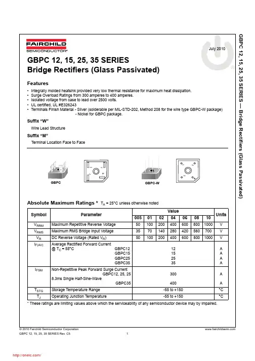
GBPC 12, 15, 25, 35 SERIES — Bridge Rectifiers (Glass Passivated)
© 2010 Fairchild Semiconductor Corporation
GBPC 12, 15, 25, 35 SERIES Rev. C51 July 2010
GBPC 12, 15, 25, 35 SERIES
Bridge Rectifiers (Glass Passivated)
Features
•Integrally molded heatsink provided very low thermal resistance for maximum heat dissipation.
•Surge Overload Ratings from 300 amperes to 400 amperes.
•Isolated voltage from case to lead over 2500 volts.
•UL certified, UL #E326243
•Terminals Finish Material - Silver (solderable per MIL-STD-202, Method 208 for the wire type GBPC-W package)
- Nickel for GBPC package.
Suffix “W”
Wire Lead Structure
Suffix “M”
Terminal Location Face to Face
Absolute Maximum Ratings * T
A = 25°C unless otherwise noted
* These ratings are limiting values above which the serviceability of any semiconductor device may by impaired.SymbolParameterValue

MB10S — Bridge Rectifier
© 2010 Fairchild Semiconductor Corporation
MB10S Rev. A01 July 2010
MB10S
Bridge Rectifier
Features
•Low leakage
•Surge overload rating : 35 amperes peak.
•Ideal for printed circuit board.
•UL certified, UL #E111753 and E326243.
Absolute Maximum Ratings * T
A = 25°C unless otherwise noted
* These ratings are limiting values above which the serviceability of any semiconductor device may by impaired.
Thermal Characteristics
* Device mounted on PCB with 0.5" x 0.5" (13 x 13 mm) lead length
Electrical Characteristics T
A = 25°C unless otherwise notedSymbolParameterValueUnits
V
RRMMaximum Repetitive Reverse Voltage1000V
V
RMSMaximum RMS Bridge Input Voltage700V
V
RDC Reverse Voltage (Rated V
R)1000V
I
F(AV)Average Rectified Forward Current, @ T
A = 50°C
On Glass-epoxy P.C.B.
On Aluminum substrate0.5

SymbolVDSVGSIDMTJ, TSTGSymbolTypMax360415400460RθJL300350Maximum Junction-to-Lead CSteady-State°C/WThermal CharacteristicsParameterUnitsMaximum Junction-to-Ambient At ≤ 10sRθJA°C/WMaximum Junction-to-Ambient ASteady-State°C/WWTA=70°C0.19Junction and Storage Temperature Range-55 to 150°CPower Dissipation ATA=25°CPD0.3ATA=70°C0.7Pulsed Drain Current B5Continuous Drain Current ATA=25°CID0.9Drain-Source Voltage20VGate-Source Voltage±8VAbsolute Maximum Ratings TA=25°C unless otherwise notedParameterMaximumUnitsAO7800Dual N-Channel Enhancement Mode Field Effect TransistorFeaturesVDS (V) = 20VID = 0.9 A (VGS = 4.5V)RDS(ON) < 300mΩ (VGS = 4.5V)RDS(ON) < 350mΩ (VGS = 2.5V)RDS(ON) < 450mΩ (VGS = 1.8V)General DescriptionThe AO7800 uses advanced trench technology to provide excellent RDS(ON), low gate charge and operation with gate voltages as low as 1.8V, in the small SOT323 footprint. It can be used for a wide variety of applications, including load switching, low current inverters and low current DC-DC converters.It is ESD protected. Standard Product AO7800 is Pb-free (meets ROHS & Sony 259 specifications). AO7800L is a Green Product ordering option. AO7800 and AO7800L are electrically identical.SC-70-6(SOT-323)Top ViewD1

Bezeichnung :description :AmmBmmCmmDmmEmmFmmstart of windingEigenschaften / propertiesWert / valueEinheit / unittol.Induktivität /inductance DC-Widerstand /DC-resistanceDC-Widerstand /DC-resistance Nennstrom /rated Current Sättigungsstrom /saturation current Eigenres.-Frequenz /self-res.-fequency33% Umgebungstemperatur / temperature:+20°C
Ferrit/ ferrite
ME09-04-21ME08-11-26ME08-04-14ME08-02-14NameDatum / date8x8x2
Änderung / modificationVersion 1Version 2Version 3Version 4Betriebstemp. / operating temperature: -40°C - +125°C1,0 typ.8,0 ± 0,31,80 ± 0,2
Basismaterial / base material:Draht / wire:Class H Luftfeuchtigkeit / humidity:
F Werkstoffe & Zulassungen / material & approvals: G Eigenschaften / general specifications:
Freigabe erteilt / general release:Kunde / customer
...........................................................................................8,0 ± 0,3