ELLIOTT__压缩机中文技术手册
- 格式:pdf
- 大小:1.26 MB
- 文档页数:116
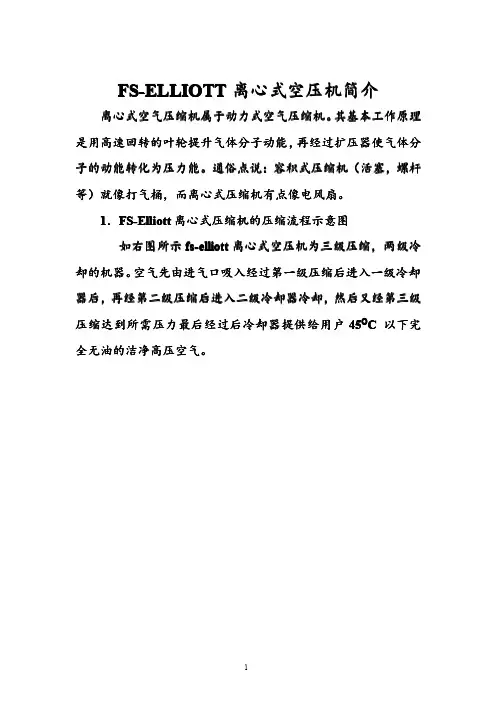
FS-ELLIOTT 离心式空压机简介离心式空气压缩机属于动力式空气压缩机离心式空气压缩机属于动力式空气压缩机。
其基本工作原理是用高速回转的叶轮提升气体分子动能是用高速回转的叶轮提升气体分子动能,,再经过扩压器使气体分子的动能转化为压力能子的动能转化为压力能。
通俗点说通俗点说::容积式压缩机容积式压缩机((活塞活塞,,螺杆等)就像打气桶,而离心式压缩机有点像电风扇。
1.FS-Elliott 离心式压缩机的压缩流程示意图如右图所示fs-elliott 离心式空压机为三级压缩,两级冷却的机器却的机器。
空气先由进气口吸入经过第一级压缩后进入一级冷却器后器后,,再经第二级压缩后进入二级冷却器冷却再经第二级压缩后进入二级冷却器冷却,,然后又经第三级压缩达到所需压力最后经过后冷却器提供给用户45O C 以下完全无油的洁净高压空气。
2.离心式压缩机的机头结构图右图是离心式压缩机的机头结构图。
它可以清楚的显示出三级压缩的离心式压缩机的结构却如此的简洁。
3.我们提供的是完全无油的洁净压缩空气离心式空气压缩机润滑油只用来润滑轴承及齿轮作为压缩空气的叶轮,蜗壳,扩压器均不接触润滑油。
右图为fs-elliott所采用的水平分离式碳环轴封元件。
它分为气侧碳环和油侧碳环。
两组碳环之间再采用仪表风气幕密封进行双重保护:防止在碳环损坏情况下油气窜至气侧影响气质。
4.世界顶级的设备当然采用世界水平的零部件a.fs-elliott离心式空压机采用目前世界上最先进的后倾式叶轮,采用不锈钢精密加工制成。
此种叶轮具有流量调节范围大,操作性很稳定的优点!b。
先进的水平剖分式可倾瓦块轴承这是fs-elliott公司为适应离心机的运行工况专门设计的。
现在世界上例如fs-elliott这样的高档离心式压缩机均采用此种轴承。
它轴向径向双向止推,巴氏合金的止推面,具备独特的自动调心功能,可以安全的运行于各种工况c。
采用独特的短轴设计将转子振动降至最低。
Manufactured in China©2008 Alton Industries Group, Ltd. – All Rights ReservedOPERATOR’SMANUALITEM#AT01204-6-Page 2-This manual contains information that relates to PROTECTING YOUR SAFETY and PREVENTING EQUIPMENT PROBLEMS and is very important for you to know and understand. We use the symbols below to help you recognize this information.POTENTIAL HAZARD THAT WILL RESULT IN SERIOUS INJURY OR LOSS OF LIFEPOTENTIAL HAZARD THAT COULD RESULT IN SERIOUS INJURY OR LOSS OF LIFEPOTENTIAL HAZARD THAT MAY RESULT IN MODERATE INJURY OR DAMAGE TO EQUIPMENT1. RISK OF EXPLOSION OR FIRE.Never spray flammable liquids in a confined area. It is normal forthe motor and pressure switch to produce sparks while operating. If sparks come into contact with vapors from gasoline or other solvents, they may ignite and cause fire or explosion. Do not smoke while spraying. Do not spray where sparks or flame are present. Keep compressor as far from spray area as possible. Always operate the compressor in a well-ventilated area.2.RISK OF ELECTRIC SHOCK. A licensed electrician in accordance with all local and national codesmust install all wirings. To avoid electric shock, NEVER use an electric air compressor outdoors when it is raining or on a wet surface.3. RISK OF BURSTING. Rust can weaken the tank.Drain the condensed water from the tank aftereach use to reduce rusting. Welding or modifications on the air tank can severely impair tank strength and cause an extremely hazardous condition. So DO NOT weld, drill or modify the air tank of this compressor. If a leak is detected in the tank, replace the tank right away.4. RISK OF INJURY. ALWAYS shut off the compressor, remove the plug from the outlet and bleed allpressure from the system before servicing the compressor or when the compressor is not in use. Do NOT use the unit with the shrouds removed. Contact moving parts could cause serious injury.5. RISK OF BURSTING. Check the maximum pressure rating in the manual or the serial tag label.Compressor outlet pressure must be regulated so as to never exceed the maximum pressure rating. Relieve all pressure through the hose before removing or attaching accessories.6. RISK OF BURSTING. DO NOT adjust the pressure switch or relief valve for any reason. They havebeen preset at the factory for the maximum pressure of this unit. If the pressure switch or the relief valve are tampered with, personal injury or property damage may occur.7. RISK OF BURNS. Pump and manifold generate high temperature. To avoid burns or other injuries,DO NOT touch the pump, manifold or transfer tube while the unit is running. Allow the parts to cool before handling or servicing. Keep children away from the compressor at all times.8. RISK TO BREATHING. Be certain to read all labels when you are spraying paints or toxic materials,and follow the safety instructions. Use a respirator mask if there is a chance of inhaling anything you are spraying. Also, NEVER directly inhale the compressed air produced by a compressor.9. RISK OF EYE INJURY. ALWAYS wear ANSI Z87.1 approved safety goggles when using an aircompressor. NEVER point any nozzle or sprayer toward a person or any part of the body. If the spray penetrates the skin, serious injury may occur.1. Pull the pressure relief valve ring daily to ensure that the valve is functioning properly.2. The unit must be kept a minimum of 12 inches from the nearest wall, in a well-ventilated area forcooling.3. Protect the air hose and electric cord from damage and puncture. Inspect them weekly for weak orworn spots and replace if necessary.4. Always wear hearing pretection when using an air compressor. Failure to do so may result inhearing loss.5. Operation of the unit should always be in a position that is stable. Never use the unit on a rooftop orelevated position that could allow the unit to fall or be tipped over.-Page 3-B A CDEFGHIJK A--------ELECTRIC MOTOR B--------AIR COMPRESSOR PUMP C--------PRESSURE SWITCH D--------PRESSURE RELIEF VALVE E--------AIR PRESSURE REGULATOR F--------TANK PRESSURE GAUGE G--------REGULATED PRESSURE GAUGE H--------AIR LINE OUTLET I---------AIR TANK DRAIN VALVE J---------AIR TANK K--------POWER CORD-Page 4-A. ELECTRIC MOTOR: The motor is used to power the pump. It has a thermal overload protector and anautomatic reset. If the motor overheats for any reason, the thermal overload protector will shut it down to prevent the motor from being damaged. The motor will automatically restart when it completely cools.B. AIR COMPRESSOR PUMP: The pump is used to compress the air and discharge it into the tank viathe piston moving up and down in the cylinder.C. PRESSURE SWITCH: The switch is used to start or stop the air compressor. It is operated manually.When in ON position, it allows the motor to start when the air tank pressure is below the factory set cut-in pressure and allows the motor to stop when the air tank pressure reaches the factory set cut-out pressure. ALWAYS set this switch to OFF when the unit is not being used, and before unplugging the unit.D. PRESSURE RELIEF VALVE: The valve is used to prevent system failures by relieving pressure fromthe system when the pressure reaches the preset level while the pressure switch does not shut down the motor. It will pop open automatically or you can pull the ring on the valve to make it.E. AIR PRESSURE REGULATOR: The regulator is used to adjust line pressure to the tool you are using.Turn the knob clockwise to increase pressure and counterclockwise to decrease pressure.Never exceed the maximum working pressure of the tool.F. TANK PRESSURE GAUGE: The gauge is used to measure the pressure level of the air stored in thetank. It is not adjustable by the operator, and does not indicate line pressure.G. REGULATED PRESSURE GAUGE: The gauge is used to measure the regulated outlet pressure.H. AIR LINE OUTLET: The outlet is used to connect 1/4” NPT air hose.I. AIR TANK DRAIN VALVE: The drain valve is used to remove moisture from the air tank after the unit isshut off.Never attempt to open the drain valve when over 10 PSI of air pressure is in the tank.J. AIR TANK: The tank is used to store the compressed air.K. POWER CORD: This product is for use on a nominal 115 volt circuit and should be grounded. A cordwith a grounding plug, as K showed, shall be used. Make sure that the product is connected to an outlet having the same configuration as the plug (see Figure 1). No adapter should be used with this product.Check with a licensed electrician if the grounding instructions are not completely understood, or if in doubt as to whether the product is properly grounded. Do not modify the plug provided. If it will notfit the outlet, have the proper outlet installed by a licensed electrician.Improper installation of the grounding plug will resultis necessary, do not connect the grounding wire to either flat blade terminal. The grounding wire is in green outer surface.Figure 1Grounded outlet 115V/13 AGrounding Pin Plug -Page 5-1. Unpack the air compressor and inspect the unit fordamage and parts. If the unit has been damaged or some parts are missing, contact the agent immediately.2. Check the serial tag label to ensure that it has therequired pressure rating for its intended use.3. Take out two(2) wheels(A), two(2) bolts(B), four(4)washers(C), two(2) nuts(D) from the bag and install them on the foot section of the tank. (See Figure 2)4. Unpack the smaller plastic bag with the air filterincluded and have the air filter (A) assembled on the pump. (See Figure 3)5. Locate the compressor according to the followingguidelines:a. Set the compressor in a position near agrounded electrical outlet.b. The compressor must be at least 12 inchesaway from any wall or obstruction, in a clean,well-ventilated area, to ensure sufficient airflow and cooling.c. The compressor must be level to ensureproper drainage of the moisture in the tank.d. In cold weather, store the compressor in aheated building when not in use. This willreduce problems with motor starting andfreezing of water condensation.6. Connect an air hose with a 1/4” NPT fitting kit to thecompressor air line outlet. Figure 2DCAB-Page 6-Figure 3NOTE: The pump is shipped WITHOUT oil. Before starting, thebreak-in oil provided in an oil bottle should be poured in the pump through the oil nozzle. The break-in oil should be changed after 8 hours of operation. To reduce maintenance and repair problems, use only premium compressor oil. SAE 10W-30 all weather air compressor oil is recommended for general use.1. Check the oil level in the pump through the oil sight glass.The pump oil level must be between A1 and A2. Do not overfill or underfill. (See A)2. Turn the pressure switch to the OFF position (See B)3. Open the tank drain valve (See C). Turn in the counter-clockwise direction. 4. Plug in the power cord5. Turn the pressure switch to the ON position (See D). Theunit will start. Allow the unit to run for half an hour to break in the internal parts. After about half an hour, if the unit does not operate properly, shut down immediately and contact Product Service.6. After half an hour, turn the pressure switch to the OFF position.7. Close the tank drain valve. Turn in the clockwise direction.8. Turn the pressure switch to the ON position. The unit willstart and fill the tank to the cut-out pressure and stop.NOTE: The pressure switch will restart the motor automatically as compressed air is used. 1. Before starting, check the oil sight glass to ensure that oillevel in the pump is at the required level.2. Turn the pressure switch to the OFF position.3. Close the tank drain valve.4. Plug in the power cord.5. Turn the pressure switch to the ON position.6. Adjust the pressure regulator to the working pressure ofthe tool.When adjusting from a higher to a lower pressure, turn the knob counterclockwise past the desired setting, and then turn clockwise to reach the desired pressure. DO NOT exceed operating pressure of the tool or accessory being used. 1. Turn the pressure switch to the OFF position. 2. Unplug the power cord.3. Reduce pressure in the tank through the outlet hose. Youcan also pull the relief valve ring and keep it open to relieve pressure in the tank. (See E)Escaping air and moisture can propel debris that drain valve.CLOSEOPENEOFFONBCD-Page 7-Regular maintenance will ensure trouble free operation. The items listed in the chart should be inspected on a regular basis.ITEM DESCRIPTIONSERVICEINTERVALDrain the tank To prevent corrosion of the tank from the inside, the condensation must be drained at the end of every workday. Be sure to wear protective goggles. Relieve the air pressure in the system and open the drain valve on the bottom of the tank to drain.DailyCheck the oil Check the oil level in the pump through the oil sight glass. The pump oil level must be within the red circle. Do not overfill or underfill.DailyCheck the relief valve Pull the relief valve on the ring daily to ensure that it is operating properly and to clear the valve of any possible obstructions.DailyClean the air filter A dirty filter will reduce the unit’s performance and life.To avoid any contamination inside the pump, the filter should be cleaned frequently and replaced on a regular basis. Foam filter should be cleaned in warm and soapy water.WeeklyTest for leakage Check all connections to see if tight. A small leak in any of the tank, hoses, pipe connections or transfer tubes will absolutely reduce the unit’s performance.Spray a small amount of soapy water around the area of the suspected leak with a spray bottle. If bubbles appear, repair or replace the faulty component. Do not over tighten any connections.N/AStorage Before storing the unit for a long period, use an air blow gun to clean all dust and debris from the compressor. Disconnect and coil the power cord up. Clean the filter element and filter housing. Drain all moisture from the tank. Pull the pressure relief valve to release all pressure from the tank. Cover the entire unit to protect it from moisture and dust.N/A-Page 8-NOTE: Troubleshooting problems may have similar causes and solutions.PROBLEM POSSIBLE CAUSE SOLUTIONPower cord not plugged in Plug cord into grounded outlet Pressure Switch in “OFF”positionTurn switch to “ON” positionWrong gauge wire or length of extension cord Check chart on page 2 for proper gauge wire and cord length Motor thermal overload switch tripped Turn air compressor off, wait until motor is cool, then check motor circuit breakerFuse blown or circuit breakertripped-Replace fuse or reset circuit breaker -Check for proper fuse amperage-Check for low voltage conditions-Disconnect any other electrical appliances from circuit or operate compressor on its branch circuitAir tank pressure exceeds preset pressure switch limit Motor will start automatically when tank pressure drops below cut-in pressure of pressure tank. Check valve stuck openRemove and clean or replace Motor will not run or start Loose electrical connections Contact authorized service centerPossible defective motor, capacitor or check valveContact authorized service centerPressure switch does not shut off motor when air compressor reaches cut-out pressure and safety relief valve activatesMove the pressure switch to the OFF position. If the motor does not shut off, unplug the air compressor. If the electrical contacts are welded together, replace the pressure switch.Motor runs continuously when in the Start/Stop optionAir compressor not large enoughCheck air requirement of accessory used. If it is higher than CFM and pressure supplied bycompressor, a larger compressor is needed. Mostaccessories are rated at 25% of actual CFM while running continuously. Regulator does not regulate pressureDirty or damage regulator internal parts.Replace regulator.Fittings leakCheck fittings with soapy water. Tighten or reseal leaking fittings. But do not over tighten. Tank drain valve is open Close drain valveRestricted air intakeClean or replace air filter element. Prolonged excessive use of air Decrease amount of air used Hole in air hose Check and replace if necessaryTank leaksReplace unit immediately. DO NOT attempt to repair.Low pressure or not enough airValve leaksCheck and replace worn parts.Moisture in discharge airCondensation in air tank causedby high level of atmospherichumidity or air compressor did not run long enough.Drain air tank after each use. Drain air tank more often in humid weather and use an air line filter. Poor ventilationRelocate compressor to an area with cool, dry andwell-circulated air.Dirty cooling surfacesClean all cooling surfaces of pump and motorthoroughly.OverheatingLeaking valve Replace worn parts and reassemble with newseals.-Page 9-P/N DESCRIPTION QTY P/N DESCRIPTION QTYcover 11 Shroud 1 12Handle2 Wheel kit 2 13Pressure Switch 1fitting 13 Fan 1 14Adapter4 Capacitor 1 15Regulator 15 Air filter 1 16Pressure gauge 26 Pump/motor assembly 1 17Relief valve 1tank 1 7 Elbow 1 18Airkit 2 plug 1 19Pad8 Oilfill9 Transfer tube w/fins 1 20Drain valve 110 Bleeder tub 1 21Oil sight glass 111 Check valve 1 22Power cord 1-Page 10-。

档案号:手册编号:中石油兰州石化公司60万吨/年乙烯改扩建工程乙烯装置丙烯制冷压缩机601JT透平操作说明书合同号:项目编号:R05T000703制造厂家:Elliott Ebara Turbomachinery Corp.二○○六年四月目录介绍 (1)关于开箱后的操作程序说明 (1)供汽 (2)EBARA公司关于蒸汽纯度指标的说明 (2)安全注意事项 (3)控制系统说明 (4)执行机构 (4)TM25执行机构 (4)正确过滤 (4)跳车阀和节流阀 (5)系统操作 (5)首次开车前的准备工作 (5)关于蒸汽透平系统初次开车的建议 (8)透平脱机运行检查 (9)透平超速试验 (16)调速器超速跳车试验 (16)联机运行检查 (17)稳定透平速度 (18)热矫正检查 (18)振动能级 (18)开车程序 (18)常规操作 (19)机组停车 (19)正常停车程序 (19)紧急停车(跳车指令) (20)运行检查 (20)日常机组运行检查 (20)自动密封蒸汽和泄流系统 (21)旋转装置的运行 (22)透平操作数据表(3-1) (23)冷开车曲线图(3-1) (24)蒸汽透平性能曲线说明 (26)透平预测性能一览表 (27)埃利奥特公司对蒸汽流量与透平轴功率的预测性能曲线 (29)蒸汽流量与透平排气压力的设计操作限定值 (30)第三章:透平操作说明书(兰州60万吨乙烯改造项目丙稀(译者注:请确认plopylene是否拼写有误)制冷压缩机601JT驱动装置)EBARA系列编号:R05T000703机架编号:SNV-9Elliott SNV-9型透平为多级、多阀门、凝汽式、单控制抽汽式蒸汽透平。
本透平则配有旋转装置。
介绍:认真遵循本说明可使设备达到设计性能和长期运行。
设备成功运行关键在于认真安装,仔细开车,并在重大质量修理工作发生之前制定一套维修计划。
设备的开、停车程序依其特殊的设计而定。
本说明书旨在对设备的开、停车程序提供指导。
螺杆空气压缩机使用说明书在安装或第一次起动压缩机前,请仔细阅读本手册,清楚了解压缩机的有关知识以及操作维修的注意事项。
请把本手册与机器一同移交使用者。
本技术手册内有重要的安全信息,应一直与压缩机一起保存。
目录1、产品说明 (2)2、工作原理 (4)3、主要技术参数 (5)4、主要结构 (8)5、管路流程图 (9)6、电气原理图 (10)7、工频控制器基本操作及参数设置 (12)8、变频控制器基本操作及参数设置 (18)9、警告及注意事项 (35)10、设备安装 (38)11、设备操作 (38)12、使用和维护 (40)13、故障和排除 (46)1 产品说明1.1 有关压缩机的说明本公司螺杆压缩机是经多年研究开发的成果。
这些先决条件与高质量标准结合,可保证制造的螺杆压缩机寿命长、可靠性高、运行效益高。
产品能够满足所有环保要求。
1.2 使用范围本系列机器和机组是根据已成熟的技术和公认的安全规则生产的。
然而若出现以下情况,则仍可能对使用者或第三方的生命和肢体造成威胁,或对机器和其他物质财产带来损害:●使用范围不正确●由不合格人员操作●不合理地修改或改变机器●不遵守安全规则因此,任何有权对机器进行操作、维护或修理的人员必须阅读并遵守安全规程。
需要时,可以要求签字对此进行确认。
此外,还必须遵守:●有关的事故防范规则●公认的安全法规●国家法规本系列机器和机组必须在完善的技术条件下使用,必须根据操作手册规定的使用范围和指南进行使用,使用人员必须有安全意识,能充分认识操作机器中存在的危险。
若发生任何功能性故障,尤其是影响安全的故障,都必须及时修理(或请别人修理)!在使用范围内操作机器的含义中,还包括应遵守操作手册中的各项指南,按规定进行检查和保养等。
1.3保养本机必须精心维护,以使螺旋压缩机或压缩机组能满足各种不同要求。
因此必须坚持按规定的保养期限对机器仔细进行维护保养,在工作环境恶劣的情况下尤其应这样做。
服务出现故障或需要备件时,请与特约本公司压缩机商家联系。
Oil-free rotary screw compressorsZR 300-750 & ZR 400-900 VSDSetting the standard in energy efficiency, safety and reliability The shortest route to superior productivity is to minimize operational cost while maintaining an uninterrupted supply of the right quality of air.The Atlas Copco Z compressor series is focused on effectively saving energy, ensuring product safety – only oil-free machines exclude contamination risks for 100% – and guaranteeing the utmost reliability around the clock. And not just today, but day after day, year after year, with minimal maintenance cost, few service interventions and long overhaul intervals.Highest reliabilityFor 60 years, Atlas Copco Z compressors have set the benchmark for durability. T hey are built using long-standing internal engineering practices, and are designed and manufactured according to ISO 9001, ISO 14001, ISO 22000 & OHSAS 18001. The high-end ZR uses time-proven state-of-the-art screw technology, cooling and pulsation dampers and providesyou with the highest reliability.100% oil-free compressed airThe ZR offers you 100% pure, clean air that complies withISO 8573-1 CLASS 0 (2010) certification. T his means zero riskof contamination; zero risk of damaged products; zero risk of losses from operational downtime; and zero risk of damaging your company’s hard-won professional reputation. Maximum energy efficiencyThe ZR’s superior oil-free screw elements provide the optimum combination of high Free Air Delivery (FAD) with the lowest energy consumption. Ample sized cooling, low pressuredrops and an extremely efficient drive train result in the highest compressor package efficiency.The most complete packageWith the ZR compressor, Atlas Copco provides a superior solution without hidden costs. T he totally integrated, ready-to-use package includes internal piping, coolers, motor, lubrication and control system. Installation is fault-free, commissioning time is low and no external instrument air is required.You simply plug and run.Global presence - local serviceOur aftermarket product portfolio is designed to add maximum value for our customers by ensuring the optimum availability and reliability of their compressed air equipment with the lowest possible operating costs. We deliver this complete service guarantee through our extensive service organization,maintaining our position as leader in compressed air.100% certified oil-free airAtlas Copco is renowned for designing and manufacturing some of the most durable oil-free screw compressors. T he ZR high-end rotary screw compressor comes out of this strong tradition. Ideal for industries where high-quality oil-free air is key, the ZR offers the highest reliability and safety in combination with low energy costs.Electronics• Clean, dry, high-quality air (Class 0) is essential,produced with optimal energy efficiency.• Applications include the removal of microscopic debris fromthe surfaces of computer chips and computer boards.T extiles• Easy and quick installation.• A completely, fully integrated, ready-to-use solution.Oil & gas• Years of experience in providing compressedair for the oil & gas industry.• 100% oil-free compressed air for control/instrumentair or buffer air.• Strong global support network to provide 24/7 assistance.Automotive• To maximize productivity in the automotive industry,downtime has to be eliminated.• An integrated package designed for long-lastingperformance is crucial.Class 0: the industry standardOil-free air is used in all kinds of industries whereair quality is paramount for the end product and production process. T hese applications includefood and beverage, pharmaceutical, chemical and petrochemical, semiconductor and electronics, the medical sector, automotive paint spraying, textile and many more. In these critical environments, contamination by even the smallest quantities ofoil can result in costly production downtime and product spoilage.First in oil-free air technologyOver the past sixty years Atlas Copco has pioneered the development of oil-free air technology, resulting in a rangeof air compressors and blowers that provide 100% pure,clean air. T hrough continuous research and development,Atlas Copco achieved a new milestone, setting the standard for air purity as the first manufacturer to be awarded CLASS 0 certification. Eliminating any riskAs the industry leader committed to meeting the needs of themost demanding customers, Atlas Copco requested the renowned TÜV institute to type-test its range of oil-free compressors and blowers. Using the most rigorous testing methodologies available, all possible oil forms were measured across a range of temperatures and pressures. T he TÜV found no traces of oil at all in the outputair stream.concentration in total oil content).321High-efficiency coolers and water separator• Corrosion resistant stainless steel tubing.• Highly reliable robot welding; no leakages.• Aluminium star insert increases heat transfer.• Water separator with labyrinth design to efficiently separate the condensate from the compressed air.• Low moisture carry-over protects downstream equipment.3World-class oil-free compression element• Unique Z seal design guarantees 100% certified oil-free air.• Atlas Copco superior rotor coating for high efficiency and durability.• Cooling jackets.2Throttle valve with load/unload regulation• No external air supply required.• Mechanical interlock of inlet and blow-off valve.• Low unload power.1* Only for ZR water-cooled versions.45Powerful motor + VSD• TEFC IP55 motor protects against dust and chemicals.• Continuous operation under severe ambient temperature conditions.• Direct energy savings up to 35% with Variable Speed Drive (VSD) motor.• Full regulation between 30 to 100% of the maximum capacity.4Advanced Elektronikon®• Large 5.7” sized color display available in31 languages for optimal ease of use.• Controls the main drive motor and regulates systempressure to maximize energy efficiency.5Air Water OilWater-cooled ZR PackVSD?VSD: driving down energy costsOver 80% of a compressor’s lifecycle cost is taken up by the energy it consumes. Moreover, the generation of compressed air can account for more than 40% of a plant’s total electricity bill. T o cut your energy costs, Atlas Copco pioneered Variable Speed Drive (VSD) technology in the compressed air industry. VSD leads to major energy savings, while protecting the environment for future generations. T hanks to continual investments in this technology, Atlas Copco offers the widest range of integrated VSD compressors on the market.EnergyEnergy savings with VSDInvestment MaintenanceEnergy savings of up to 35%Atlas Copco's VSD technology closely follows the air demand by automatically adjusting the motor speed. This results in large energy savings of up to 35%. The Life Cycle Cost of a compressor can be cut by an average of 22%. In addition, lowered system pressure with VSD minimizes energy use across your production dramatically.T otal compressor lifecycle cost1 The Elektronikon ® controls both the compressor and theintegrated converter, ensuring maximum machine safety within parameters.2 Flexible pressure selection from 4 to 10.4 bar withVSD reduces electricity costs.3 Specific converter and motor design (with protectedbearings) for the highest efficiency across the speed range.4 Electric motor specifically designed for low operatingspeeds with clear attention to motor cooling and compressor cooling requirements.5 All Atlas Copco VSD compressors are EMC testedand certified. Compressor operation does not influence external sources and vice versa.6 Mechanical enhancements ensure that all componentsoperate below critical vibration levels throughout the entire compressor speed range.7 A highly efficient frequency converter in a cubicleensures stable operation in high ambient temperatures up to 50°C/122°F (standard up to 40°C/104°F).8 No ‘speed windows’ that can jeopardize the energysavings and the stable net pressure. T urndown capability of the compressor is maximized to 70-75%.9 Net pressure band is maintained within 0.10 bar, 1.5 psi.Monitoring and control:how to get the most from the leastThe Elektronikon ® unit controller is specially designed to maximize the performance of your compressors and air treatment equipment under a variety of conditions. Our solutions provide you with key benefits such as increased energy efficiency, lower energy consumption, reduced maintenance times and less stress… less stress for both you and your entire air system.Intelligence is part of the package• High resolution color display gives you an easy to understand readout of the equipment’s running conditions. • Clear icons and intuitive navigation provides you fast access to all of the important settings and data. • Monitoring of the equipment running conditions and maintenance status; bringing this information to your attention when needed.• Operation of the equipment to deliver specifically and reliably to your compressed air needs.• Built-in remote control and notifications functions provided as standard, including simple to use Ethernet based communication.• Support for 31 different languages, including character based languages.• A remote monitoring system that helps you optimize your compressed air system and save you energy and cost.• It offers you a complete insight in your compressed air network and anticipates on potential problems by warning you up-front.*Please contact your local sales representative for more information.SMART LINK *:Data monitoring programOnline & mobile monitoringMonitor your compressors over the Ethernet with the new Elektronikon ® controller. Monitoring features include warning indications, compressor shut-down andmaintenance scheduling. An Atlas Copco App is available for iPhone/Android phones as well as iPad and Android tablets. It allows fingertip monitoring of your compressed air system through your own secured network.The magic formula: turbo + screwObtain the most efficient compressor solution for your high capacity application in the market by combining the advanced turbo technology of the ZH + with the regulating capabilities of the ZR screw compressor with Variable Speed Drive (VSD). Eliminating costly blow-off in all operating conditions, this combination is ideal to achieve the highest return on investment while enjoying the benefits of the ZH + turbo and ZR screw technology.Reduced blow-offWhile turbo compressors are very efficient in turndown,a lot of energy is wasted during blow-off by expanding part of the compressed air into the blow-off valve and silencer. By combining two turbo compressors in an erratically varying air demand, the expensive blow-off is reduced but not completely eliminated.Eliminated blow-offAtlas Copco's unique Variable Speed Drive (VSD) technology closely follows the air demand by automatically adjusting the motor speed. When combining the ZH + turbo compressor and the ZR screw compressor with VSD, the highest efficiency is achieved by completely eliminating blow-off.Find out how much you can saveAtlas Copco can help you map the load/air demand profile of your current compressor and blower installation and indicate potential energy savings with VSD compressors and blowers.For more information, please contact your local Atlas Copco representative.Operation without blow-offOperation with blow-off Hours of operationHours of operation04812162024Protecting your productionUntreated compressed air contains moisture and possibly dirt particles that can damage your air system and contaminate your end product. T he resulting maintenance costs far exceed air treatment costs. Atlas Copco believes in effective prevention and provides a complete range of air treatment solutions to protect investments, equipment, production processes and end products.Increase production reliabilityLow quality air heightens the risk of corrosion, which can lower the life span of production equipment. T he air treatment solutions produce clean air that enhances your system’s reliability, avoiding costly downtime and production delays.Safeguard production qualityCompressed air coming into contact with your final products should not affect their quality. Atlas Copco provides clean,dry air to protect your production and reputation in the market.Supreme energy and cost savingsAtlas Copco’s quality air solutions stand for substantial energy savings all day, every day. T aking technology to a new level,these products achieve maximum cost savings.Proven peace of mindBuilding on know-how and years of experience, the entire Atlas Copco quality air range is produced in-house and tested using the most stringent methods in the industry.A dryer solution for every needUntreated compressed air contains moisture and possibly dirt particles that can damage your air system and contaminate your end product. T he resulting maintenance costs far exceed air treatment costs. Atlas Copco believes in effective prevention and provides a complete range of air treatment solutions to protect investments, equipment, production processes and end products.Dryers overviewTo further protect your investment, equipment and processes, Atlas Copco presents a full line-up of innovative quality air solutions to suit the high quality requirements of your specific application.BD/BD +-70°C/-40°C/-20°C -94°F/-40°F/-4°FHeat reactivated adsorption dryer• Use of electrical heaters for regenerating the desiccant.• Limited pressure drop.• Variants without loss of compressed air.FD+3°C/+20°C +37°F/+68°FRefrigerant dryer• Use of cooling circuit for cooling down compressed air.• Guaranteed pressure dew points.• Lowest energy consumption in all operating conditions.• Air and water cooled variants.MD-20°C/+3°C -4°F/+37°FRotary drum heat of compression dryers• Use of freely available heat of compression.• Negligible power consumption.• Variants with extra heat augmentation for lower dew points.ND-40°C/-20°C -40°F/-4°FXD-S-20°C/+3°C -4°F/+37°FHeat of compression reactivated adsorption dryers• Use of freely available heat of compression.• Limited pressure drop.• Variants for dew point suppression and guaranteed dew point.• Variants without loss of compressed air.XD-G/XD +-G-70°C/-40°C/-20°C -94°F/-40°F/-4°F D e w p o i n t (°C )D e w p o i n t (°F )Flow (l/s)Flow (cfm)+37-4-4012002500300040005000600070008000-94Optimize your systemWith the ZR, Atlas Copco provides an all-in-one standard package incorporating the latest technology in a built-to-last design. T o further optimize your ZR’s performance or to simply tailor it to your specific production environment, optional features are available.Engineered solutionsAtlas Copco recognizes the need to combine our serially produced compressors and dryers with thespecifications and standards applied by major companies for equipment purchases. Strategically located departments within the Atlas Copco Group take care of the design and manufacturing of customized equipment to operate at extreme temperatures, often in remote locations.Innovative technologyAll equipment is covered by our manufacturer warranty.The reliability, longevity and performance of our equipment will not be compromised. A global aftermarket operation employing 360 field service engineers in 160 countries ensures reliablemaintenance by Atlas Copco as part of a local service operation.Innovative engineeringEach project is unique and by entering into partnership with our customers, we can appreciate the challenge at hand, ask the relevant questions and design the best engineered solutionfor all your needs.Options• : Optional- : Not availablePlease note the availability of the option depends on the chosen configuration.ZR 300-750(1) Unit performance measured according to ISO 1217, Annex C, Edition 4 (2009).Reference conditions:- Relative humidity 0%.- Absolute inlet pressure: 1 bar (14.5 psi).- Intake air temperature: 20°C/68°F.FAD is measured at the following working pressures: Fixed speed:- 7.5/8.6 bar versions at 7 bar.- 10/10.4 bar versions at 9 bar.For VSD: at their maximum working pressure.(2) A-weighted emission sound pressure level at the work station (LpWSAd).Measured according to ISO 2151: 2004 using ISO 9614/2 (sound intensity scanning method).The added correction factor (+/- 3 dB(A)) is the total uncertainty value (KpAd) conform with the test code.ZR 400-900 VSD (50/60 Hz)(1) Unit performance measured according to ISO 1217, Annex C, Edition 4 (2009).Reference conditions: - Relative humidity 0%.- Absolute inlet pressure: 1 bar (14.5 psi). - Intake air temperature: 20°C/68°F .FAD is measured at the following working pressures:Fixed speed:- 7.5/8.6 bar versions at 7 bar. - 10/10.4 bar versions at 9 bar.For VSD: at their maximum working pressure.(2) A-weighted emission sound pressure level at the work station (LpWSAd).Measured according to ISO 2151: 2004 using ISO 9614/2 (sound intensity scanning method).The added correction factor (+/- 3 dB(A)) is the total uncertainty value (KpAd) conform with the test code.DimensionsCA BCOMMITTED TO SUSTAINABLE PRODUCTIVITY2935 0366 20 © 2017, A t l a s C o p c o , B e l g i u m . A l l r i g h t s r e s e r v e d . D e s i g n s a n d s p e c i fi c a t We stand by our responsibilities towards our customers, towards the environment and the people around us. We make performance stand the test of time. T his is what we call – Sustainable Productivity.。

科海机房(深圳)办事处艾默生恒温恒湿空调产品资料(艾默生)力博特PEX系列恒温恒湿空调介绍一、PEX系列描述科海机房(深圳)办事处 艾默生恒温恒湿空调产品资料科海机房2二、PEX 系列技术参数1、同等制冷量条件下,占地面积最小。
侧面及背面不需要维护空间,前面只需要600mm维护空间。
2、可拆卸后搬运,保证重新组装与整机无差别,适合特殊场地搬运(如利用小电梯或狭小通道)。
3、快速除湿功能设计,能有效的降低除湿能耗。
4、Copeland(艾默生子公司)涡旋式压缩机,能效比高,运行可靠。
5、大表面积的 V 型蒸发器盘管,使热交换更快,更有效率,“V”型结构有利于蒸发器表面的空气分配更加均衡,确保节能。
6、6秒可以产生纯净蒸汽的远红外加湿系统,湿度控制精确,可以适应各种水质,清洗维护方便。
7、大屏幕LCD全中文显示屏,图形化显示多种信息,并提供帮助菜单。
8、提供先进的iCOM微处理控制器,强大的联机控制功能。
✧控制精确,PeX系列空调系统能精确地进行温湿度控制。
温度可设定在±1℃,湿度可设定在±1%RH。
✧能效高,PeX系列空调采用了Copeland高效涡旋压缩机。
该压缩机具有独特的V字形翅片管式换热器和精细设计的分液头,使得空调内部流场更加均匀,冷媒分配更加合理,从而极大地提高了换热器的换热效率,使整机达到高效节能的效果。
✧方便耐用:经久耐用的机件,结构紧凑,整体尺寸小;独特的碳钢铆钉铆接的骨架机身,既稳定坚固又容易拆分,可以实现极限条件下搬运;内外两层,中间采用防火隔热棉,机身内的保温性能良好;one-bay、two-bay、three-bay结构件通用性较高,大大降低了易消耗件(如过滤网等)的规格。
✧采用真正的模块化设计思路。
生产的单制冷回路/双制冷回路 PEX系列精密空调,可以提供单机的制冷量为20KW至100KW,并可组合在一起。
即能满足现阶段的使用,又能适应未来发展的需求,具有非常广泛的应用范围。
PISTON COMPRESSOR MANUAL REV022621Contents Safety Information 2-3 Breathable Air 3Pressurized Components 3Personal Protective Equipment 3 Nomenclature 4 Features and Extras 5-7 Pump Riser 5Belt Tensioner 5Continuous Run 6Automatic Tank Drain 7 Installation 8-16 Area 8Lifting and Movement 9General Lifting 9Anchoring 10Electrical 11-14 Piping 15-16 Pre-use Inspection 17 Operation 18Pump Times 18 Maintenance 19-20 Maintenance Schedule 19-20 Oil Change/Selection 20Oil Disposal 20 FAQ and Troubleshooting 21 Warranty Information 22-24SAFTEY INFORMATIONThis manual contains very important information to know and understand. This is to provide for SAFTEY and to PREVENT EQUIPMENT PROBLEMS. To help understand this information, observe the following:DANGER:Danger indicates and imminently hazardous situation which, if not avoided, will result in death or serious injury.WARNING: Warning indicates a potentially hazardous situation which if not avoided, could result in death or serious injury.CAUTION:Caution indicates a potentially hazardous situation which, if not avoided, may result in minor or moderate injury.NOTICE:Notice indicates important information, that if not followed, may cause damage to equipment.CALIFORNIA PROPOSITION 65WARNING:This product or its power cord may contain chemicals known to the state of California to cause cancer and birth defects or other reproductive harm. Wash hands after handling.1.Allow only trained, authorized persons who have read and understood these operating instructions to use thisequipment. Failure to follow the instructions, procedures and safety precautions in this manual can result inaccidents and injuries.2.NEVER start or operate the compressor under unsafe conditions. Tag the compressor, disconnect,and lock out all power to it to prevent accidental start-up until the condition is corrected.3.Install, use, and operate the compressor only in full compliance with all pertinent OSHAregulations and all applicable Federal, State & Local codes, standards, and regulations.4.NEVER modify the compressor and/or controls in any way.5.Keep a first aid kit in a convenient place. Seek medical assistance promptly in case of injury. Avoidinfection by caring for any small cuts and burns promptly.BREATHABLE AIR1.NEVER use air from this compressor for breathable air except in full compliance with OSHA Standards 29CFR 1910 and any other Federal, State or Local codes or regulations.2.DO NOT use airline anti-icer systems in air lines supplying respirators or other equipment used to producebreathable air. DO NOT discharge air from these systems in unventilated or other confined areas.Pressurized ComponentsThis equipment is supplied with an ASME designed and rated pressure vesselprotected by an ASME rated relief valve. Pull the ring before each use toensure the valve is functional. DO NOTattempt to open the valve while themachine is under pressure. See figure on the right.Personal Protective EquipmentBe sure all Be sure all operators and others around the compressor and its controls comply with all applicable OSHA, Federal, State and Local regulations, codes, and standards relating to personal protective equipment. This includes respiratory protective equipment, protection for the extremities, protective clothing, protective shields and barriers, electrical protective equipment, and personal hearing protective equipment.NomenclatureFeatures and ExtrasCompressors come in many shapes and sizes. Our units have several features that may or may not be present on your unit. These features may be purchased after the fact in kit form. This guide will explain the use and benefit of these features.Pump RiserBelt TensionerContinuous RunContinuous run allows the pump to turn continuously, hence the name. In this mode the unit pumps up to 140 PSI and then the valves are held close. This allows the pump to enter a free spin state where the unit is pulling in cold air and the simply cycling it back to atmosphere. This has several benefits:1.The pump is cooled during the free spin state since it has no pump load on it.2.Increased recovery time since the function cycles between 100 and 140 PSI; which is the optimal CFMwindow for the unit.3.Wear on your motor is decreased (especially single-phase units) as the unit is already in motion and will notneed the large amp draw to overcome zero movement and fight tank compression.4.Continuous run is best used in applications where CFM cannot be lost. Some examples of this are: mediablasting, painting, and prolonged grinding or resurfacing.Auto DrainAuto drains are preset timer valves that allow tank moisture to be vented as long as they are powered. The enemy of every compressor/air system is moisture. The auto drain removes some of the hassle of this by allowing the user to set a timer and walk away from the unit with the piece of mind that their system is protected.1. The drain works off a conventional 120V outlet.2. Timer has built in intervals that can be customized to the user need.3. Has a manual shut off for service and maintenance.4. The drain filter MUST be cleaned weekly to prevent drain blockage.5.Drain time knob, marked as ON:SEC , corresponds to how long the drain will run for when it comes on. This is listed in seconds.6. Drain interval knob, marked as OFF: MIN , corresponds to how long between cycles. Or how long the drainwill be OFF before it comes on again.7. The drain attaches to a ½” NPT female connection.8. The vent can blow to atmosphere; however, the drain is supplied with a drain silencer system which can beused to muffle the sound of the unit draining. This screws into the atmospheric vent location, however, it is not necessary for operation.9.A drain system can also be equipped by the user to allow moisture to drain to a separate location.10. The drain is also equipped with a test button to check function.InstallationArea1.Install compressor in a clean, dry, and well-lit area. Be sure installation area can maintain a temperaturerange between 35˚ - 110˚F.2.Allow sufficient space around the compressor for maintenance access and adequate airflow. Mount unit withthe belt guard (pulley and flywheel) side to the wall and leave a minimum of 15 inches of clearance.3.If acid is used in operating environment or air is dust laden, pipe intake to outside fresh air. Increase pipe sizeby 1/8”’ for every 20ft of run. Be sure to install a protective hood at the outside air intake location to prevent debris and foreign objects from blocking the intake pipe.4.In operating environments where excessive water, oil, dirt, acid, or alkaline fumes are present, a TEFC (totallyenclosed, fan cooled) motor is highly recommended. Check nameplates for motor type.5.Insulate cold water or tother low temperature pipes that pass overhead to avoid condensation dripping onthe compressor.6.In environments where fine dust is common such as granite, marble, or concrete plants the unit must beinstalled in a separate room with its own dedicated ventilation system.7.The unit can be stored outside under the following guidelines: It must be in a covered area out of extremeweather with no ability for moisture to get to the unit, it is also highly recommended that the unit is out of direct sunlight as it can fade and/or damage the coating on the unit. Direct sunlight may also interfere with safety decals on the unit.8.If the unit is in an enclosed space it requires proper ventilation as the ambient air temp where thecompressor is located CANNOT exceed 115 degrees F.e shims to level the compressor if installation area is not flat. This will help prevent excessive vibration andpremature pump wear.Lifting and Movement/Forklift1. Make sure lift operator stays aware while moving the compressor.2. Be sure to uncrate the compressor prior to movement. This will allow a visual reference for the balance ofthe unit.3. Be sure the load is secure and well balanced before moving the compressor.4. Make sure the forks are fully engaged and level prior to lifting or moving the unit.5. Keep the unit/load as low as possible while moving and refrain from quick changes in direction.6. For all other forklift safety standards/regulations please reference OSHA 1910.178- Powered industrialtrucks.General Lifting Information1. Carefully inspect all lifting equipment and ensure it is in good condition. Rated capacity of lifting equipmentmust exceed compressor weight. NEVER lift with under sized or damaged equipment.2. If using lifting equipment, ensure all lifting points are in good condition and tighten any loose nuts or boltsbefore lifting.3. A sling MUST be used when moving the compressor with a helicopter or other airborne equipment. Be sureto follow OSHA standards 1910 subpart N.4. Use guide ropes or equivalent to prevent twisting or swinging of the compressor while it is in the air andNEVER attempt to lift the unit in high winds. Keep compressor as low to the ground as possible.5. Keep all persons away from the compressor when it is lifted. DO NOT allow persons under the compressorwhile it is being lifted.6. DO NOT use bolts or other hooks on individual components to move the compressor.7. When moving and or placing the compressor ensure it is on/across a surface that can hold the combinedweight of the compressor and the loading equipment.AnchoringTo ensure proper and safe operation of the compressor the unit is required to be anchored to a flat, smooth,concrete floor. Compressors are also required to be on ¼ inch (6.35mm) MAXIMUM thick rubber anti-vibration pads.Recommended anchor Bolt specifications: wedge anchors; 3/8 in width by 3.5 in length.How to Anchor the Compressor1. Make sure the compressor is in the desired location and the anti-vibration pads are under the feet of thecompressor.2. Using the holes in the feet as guides, drill the holes for the anchor bolts through the vibration pads and intothe concrete.3. Thoroughly clean each hole.4. Put the Washer and Nut into place, make sure the top of the Nut is flush with the top of the anchor bolt, theninsert the anchor bolt into the hole.5. Hammer or mallet the anchor bolt down into the hole.6. Tighten each nut clockwise , DO NOTover tighten. DO NOTuse an impact to tighten the anchors.Electrical Safety1. Follow all NEC and local codes for electrical wiring. Allow only authorized service personnel or certifiedelectricians to install electrical components.2. Put unit on a dedicated circuit and make sure no other electrical equipment is wired into it. Failure to wireunit on an independent circuit can cause circuit overload and/or imbalance in motor phasing. Install proper No Fuse Breaker (NFB) according to the chart listed below. You may also reference NEC and local codes for additional support.3. Ensure incoming service has adequate ampere rating.4. Do not used mixed wire sizes when wiring the unit.5. The unit must be properly grounded. DO NOT connect ground to air or cooling lines.Wiring the Compressor1. Voltage should not vary more than 12% to ensure proper operation of the compressor.2. Wire size and breaker requirements for single phase units:**3. Wire size and breaker requirements for 3 phase units:**Wire size distances are from unit to the panel where the breaker is housed.**CAUTION: Under sizing wires and/or breakers can cause damage to the unit, possible injury to personnel, and void your warranty.4. Single phase unit, NO magnetic starter:5.Single phase unit WITH magnetic starter:6.Three phase unit wire diagram (Three phase will ALWAYS have magnetic starter):7.During initial start up of 3 phase unit, pay attention to flywheel rotation. When facing the front of thecompressor (Pressure switch/pressure gauge side) rotation should be clockwise. If rotation iscounterclockwise, switch incoming power leads at 3L2 and 5L3 (ensure power is off at the breaker before attempting any changes).Piping (Safety steps)1.Install appropriate flow-limiting valves as necessary according to pipe size(s) used and run lengths. This willreduce pressure in case of hose failure, per OSHA Standard 29 CFR 1926.302(b)(7).2.Flow-limiting valve are listed by pipe size and rated CFM. Select appropriate valves according tomanufacturer’s recommendations.e a flexible connector between compressor tank and dryer/piping system to minimize noise, vibration,pump wear, and to prevent damage to the unit or piping system.4.Install ASME code safety valves and ensure piping system is equipped with adequate condensate drains.5.Minimum pipe size for compressed air lines: (Pipe sizes are shown in inches)PISTON COMPRESSOR MANUAL REV0226216.Air systems should be checked daily for leaks. This helps to prevent unnecessary load on the compressor andhelps increase energy savings.7.Examples of air systems:Closed loop system. Install tee fitting in piping from air to minimize pressuredrop and to allow air flow in two directions.Air DropAir Drop: Install tee fitting withbranch to top to minimizecondensation.From CompressorElevation View8.Make sure any tube, pipe, fitting, or hose connected to the unit can withstand operating temperatures andretain pressure.9.Never use reducers in discharge piping. Keep all piping and fittings the same size in the piping system.WARNING: Never use plastic (PVC) pipe for compressed air. Serious injury ordeath could result. Piping MUST have a pressure rating of 200 PSI or greater.Pre-Use Inspection1. The unit is shipped with pump break-in oil and should be ready to operate. Be sure to check for proper oil levelbefore running the compressor. Break in oil should be change after 100 Hours of operation (active pumping time). See maintenance section for more information on oil changes and frequency.2. Check for proper belt tension. There should be ½ inch of belt slack/deflection. Refer to maintenance section ifadjustment is necessary.3. Inspect belts for frays or unit for an excess buildup of black rubber dust indicating belt wear.4. Check proper operation of all pop off safety valves on unit. Pull rings on valves to ensure they move and are freeof any obstructions. DO NOT pull the safety valve on the tank if there is air in the tank!5. Inspect all air lines/piping for proper for secure fit and corrosion or line degradation. DO NOT operate thecompressor with damaged lines. DO NOT use damaged or cracked air lines as a rupture could result in damage/injury to personnel or property.6. WITH UNIT LOCKED OUT (power off at source i,e. the electrical panel/disconnect) ensure all electrical wiring,including all terminals, are in good condition and are free of buildup, fraying, cracks or discoloration replace as needed. Check tightness of bolts securing wiring in place.7. Ensure unit is secured in place and has not shifted. Verify anchor bolts are in place and are in good condition. 8. Remove any loose items from around/on compressor to avoid damage to the unit. Examples would be looseclothing items, rags, papers, bottles, or any item that may have been placed on the unit. 9. Check unit for any oil leaks. If leaks are found contact manufacturer for further instructions. 10. Unit should NEVER be operated without the belt guard in place.11. Inspect Flywheel for cracks or missing fins. NEVER operate a unit with a damaged flywheel; serious injury ordeath could result. If you suspect your flywheel may have been damaged, contact technical assistance and DO NOT allow the machine to be operated.Ensure all personnel that work around or operate the compressor have read this manual and are well versed in the operation of this machinery. NEVER allow untrained personnel to operate this unit.1. Once the inspection is completed, open your discharge port (outlet ball valve). This should already be connectedto your shop airline system.2. Ensure all personnel are clear of the compressor and aware that it is being started.3. Turn the selector on your pressure switch to AUTO. This will start your compressor and allow it to fill. The tankwill fill to 175 PSI, and unless otherwise noted, will shut off. The unit will begin pumping again once the tank is drained down to approximately 135 PSI. ***This may vary based on features, if your unit is equipped withCONTINOUS RUN , the unit may perform differently then specified in this step. (Check the FEATURES section for more information)4. Oil pressure on start up will vary due to ambient temperatures but should not exceed 100 PSI. Once the unit isallowed to run a few cycles and come to optimal operating temperature, oil pressure should stabilize at 20-35 PSI. If the oil pressure remains high or drops too low, it can be adjusted as follows:Pump Up Time (General)Compressor maintenance must be performed as described in the maintenance schedule, failure to do may lead to compressor/component breakdown and void compressor warranty.Maintenance ScheduleThe table below is a generalized maintenance schedule based on the normal usage of a compressor. Your specific needs may vary based on operating environment and duty.Frequency of these changes are a generalization and may be subject to change based on compressor environment, hours, and application.Oil ChoiceIt is strongly advised to use only Airbase Industries piston compressor oil. Check with your warranty/extended warranty guidelines to verify oil selection and use. Oil used in the compressor must fall under the following criteria: synthetic, SAE grade 30, non-detergent, piston compressor oil.Oil DisposalCompressor oil is not trash and MUST NOT be disposed of in regular trash or discarded into the environment. You MUST dispose of waste oil from your unit per all applicable federal, state, and/or local codes. Failure to do so may damaged the environment and subject yourself and/or your business to fines and legal issues.TroubleshootingSome unit issues can be fixed simply by verifying the following guide. It is advised to go through the guide prior to calling technical support to help expedite the assistance process.Warranty Statement•Standard Warranty: That each compressor unit is free from defects in material, workmanship, and parts for1 year from the date of delivery. This Standard Warranty includes 1 year of warranty labor from anauthorized technician. Manufacturer is not responsible for downtime during warranty service. If downtime is necessary, it is at the owner’s discretion, obligation, and expense, to h ave a redundant compressor.• Parts shipped for warranty repairs shall only include ground freight charges for the first 90 days of the warranty period, thereafter owner is responsible for all freight charges of parts shipped for warranty. Any and all expre ss shipping charges of warranty parts would be at the owner’s expense. Standard technicalassistance is provided at no charge during and after the standard warranty period.*Standard warranty has no obligation to maintain warranty status, warranty will expire one year from date of delivery. Please see available options below to extend your warranty.•Extended Warranty: Manufacturer will extend your standard 1-year warranty to full 5 years when you opt to register for the extended warranty plan that includes using our SMART OIL™ and following all routinemaintenance set forth. Parts shipped for warranty repairs shall only include ground freight charges for the first90 days of the warranty period, thereafter owner is responsible for all freight charges of parts shipped forwarranty. Any and all express shipping charges of warranty parts would be at the owner’s expense. Standard technical assistance is provided at no charge during and after the standard warranty period.Required maintenance schedule to maintain warranty status.➢All units are shipped with break-in oil and must be changed no less than 70 hours to i nsure gasket seating.➢After the 100 hours of break-in, you must change the oil.➢Thereafter Oil Should be changed every 6 months or 1000 hours whichever occurs first.➢Always maintain proper oil level in unit. If the unit runs out of oil due to neglect the warranty w ill be void.➢Use only manufacturer approved oils in your compressor, or your warranty is void.➢All stock orders by vendor/purchaser are required to purchase two service kits at time of purchase per unit.➢All stocking orders will have a 6-month grace period for warranty registration. After that time the unit must be registered, or warranty may be void.**Extended Limited Lifetime Pump Warranty With participation in our SMART OIL™ extended auto shipprogram will extend your warranty plan to **Limited Lifetime Warranty on the pressure lubricated pump.All other non-wear and tear components to 10 years. SMART OIL™ not only extends the life of yourcompressor pump, it also can reduce operating noise levels and can create further energy savings.Warranty repair parts under the Limited Lifetime warranty will not include any shipping charges beyondthe Standard Warranty, therefore owner is responsible for all freight charges for warranty parts. This planincludes our advanced technical air support. Smart Tech Support provides you with the highest level oftechnical support. Smart Tech support is an interactive support team available to you at your fingertips byjust downloading a free app. The app provides free remote meetings, interactive touch display, real livepersonal to assist.Limited Lifetime Warranty is not prorated and has no hour limits.**Limited Lifetime Warranty, non-prorated, no hour limits. In the case the product has been discontinuedat any point the Limited lifetime Pump warranty will last five years past the discontinued date. Warrantorhas discretion to substitute parts with current model for the five-year duration.*In order to maintain Limited Lifetime Warranty status, the owner must adhere to and purchase the required maintenance items as scheduled below utilizing our Smart Whisper Blue Auto Ship program:Required maintenance schedule to maintain warranty status.➢All units are shipped with break-in oil and must be changed no less than 70 hours to i nsure gasket seating.➢After the 100 hours of break-in, you must change the oil.➢Thereafter Oil Should be changed every 6 months or 1000 hours whichever occurs first using only our Smart Whisper Blue Oil➢Always maintain proper oil level in unit. If the unit runs out of oil due to neglect the warranty w ill be void.➢Use only Smart Whisper Blue Oil and filters purchased from original manufacturer in y our compressor, or your warranty will be voided.➢Must be an active member of auto ship program.➢All stock orders by vendor/purchaser are required to purchase two service kits at time of purchase per unit.➢All stocking orders will have a 6-month grace period for warranty registration. After that time, the unit must be registered, or warranty may be void.•Warranty shall not apply, and manufacturer shall not be responsible nor liable for:➢Routine service such as oil changes, filter replacements, gasket tightening t o correct oil seepage or drive belt tightening and valve cleaning and are not covered under warranty.➢Consequential damages such as but not limited to cost of loss of business, product damage, or down time.➢Acts of nature, over abuse, malicious destruction, improper maintenance, undersized equipment➢In the case the product has been discontinued at any point the *Limited lifetime warranty w ill last five years past the discontinue date. Manufacturer has discretion to substitute parts with currentmodel for the five-year duration.➢Deviation from operating instructions or specifications➢Labor charges for repairs or maintenance made by person(s) other than an authorized, a pproved service technician or any labor after the 1-year Standard Warranty expires.➢Normal wear and tear parts included but not limited to valves (intake/suction, check, b lowdown, thermo, pop off, unloader), and ball valves. Belts, shaft seals, load/unloader solenoids, sensors(temperature or pressure), Electrical contractors and relays, and any parts with a routinemaintenance scheduleWarranty shall be voided under the following conditions: Exposing electrical components to rain or water or installing the unit in a hostile environment such as acid vapors or any caustic or abrasive matter that may be ingested into the pump or installing the unit in an enclosed area where lack of cooling ventilation is present, such as in boiler or equipment rooms where the ambient air exceeds 100F.Further exclusions include failure to fully and completely follow the guidelines set forth in the manual. Of specific note is environments where fine dust is common, such as granite, marble or concrete plants, the compressor MUST be installed in a separate area with its own dedicated ventilation. FAILURE TO PROVIDE THIS DUST FREE OPERATING AREA VOIDS THE WARRANTY.Parts used for warranty purposes must be supplied by original manufacturer. Warranty work should be performed only by an approved technician. If any maintenance (other than routine maintenance) is performed by a non-approved Technician, written pre-approval must be obtained from manufacturer, to prevent voiding this warranty. Failure to fully comply with this warranty and fully comply with the manual instructions will void this warranty.The oil purchase and maintenance program are effective as of Jan.2020。
亚洋压缩机说明书
1、亚洋压缩机为立式、四级四列、双作用、水冷却、无润滑、活塞式氧气压缩机。
可用于大中型空分设备和石油化工等其它工业部门。
该机主要特点为:
a.结构紧凑、占地面积小、重量轻。
b.动力平衡性好、运转平稳可靠。
c.振动和噪音小。
d.运行经济性好。
e.导向环、活塞环、填料磨损均匀、寿命长。
f.外形美观。
2、主要参数
气体系统览与源文档一致下载高消无水印低压氧气,经吸入滤清器过滤,再经各级压缩及冷却后,送入后装置。
3、具体走向如下:
吸入滤清器-一级气缸压缩-一级排气缓冲器-一级换热器-二级吸气缓冲器-二级气缸压缩-二级排气缓冲器-二级换热器-三级进气缓冲器三级气压缩-三级排气缓冲器-三级换热器-四级进气缓冲器-四级气缸压缩-四级排气缓冲器-后续装置。
四级排气缓冲器后设有排气截止阀及放空阀文档一放空阀为气体紧急放空、吹除及试车用。
阿特拉斯控制说明书(空压机)1.控制说明书1.1 概述离心式压缩机的流量可以通过调整导叶和放空阀开度来调节。
关放空阀和开导叶均会增加压缩机流量和排压。
关导叶和开放空阀会减小流量和降低排压。
排压控制器通过分程控制导叶和回流阀/放空阀来控制压缩机排压。
透平压缩机通过喘振控制器保证在最小的体积流量下可以稳定操作而不发生喘振。
当体积流量低于这个最小体积流量时,流动停止,这种现象被称为“喘振”,这会对设备造成损坏应当予以避免。
为保证在压缩机减少流量时也能在稳定区域内运行,压缩机设计了回流/放空阀补偿电流和最小体积流量的差异。
回流/放空阀同坐喘振控制器控制。
在稳定和不稳定操作区域之间的分隔线被称为喘振线,这条线的轨迹依赖于很多因素(温度、压力等)为确保稳定的控制特性,在喘振线与喘振控制线之间定义一个安全余量。
最大压缩机排压通过作用在回流/放空阀上的排压限制控制器加以限制。
主电机最大电流/功率通过作用在进口导叶上的电流/功率限制控制器加以限制。
1.2喘振控制器喘振控制器作为一个安全控制器,它只在极端的操作条件下才起作用。
它的作用是使压缩机远离喘振,最终对喘振控制器的调整由阿特拉斯人员在试车阶段确定并用密码保护。
喘振控制器的控制变量X为压缩机排出侧实际流量。
它由下列测量值计算得出公式:Dpflow流量计前后压差转换为KPaPflow流量计处压力转换为KPa absTflow 流量计处温度转换为开氏温度KKI dishflow 体积排出流量计算常数喘振控制器的参考变量W是一个固定值(“固定的回流/放空线”=在喘振线的控制变量+安全余量)由阿特拉斯技术人员在试车时设定。
喘振控制器可以选择用能随着当前压缩机操作点变化而改变的动态参考变量来控制。
对于增加的控制变量,动态参考变量随着当前操作点的变化立即改变。
当然,是以常数距离改变的。
对于减少的控制变量,在减小到固定参考变量(喘振线+安全余量后的控制变量)之前,动态参考变量下降时会有延时。
图1-1机(双门)1.2 型号说明PEX系列空调型号说明见图2-3所示。
P 1 020 U W P M S 1 R加湿类型:0-无加湿;R-红外加湿;S-电极加湿再热类型:0-无电加热;1-一级电加热;2-二级电加热显示屏形式:S-小显示屏;L-大显示屏电源形式:M-三相/50Hz/400V系统配置:R-制冷剂为R22,涡旋压缩机2个;P-制冷剂为R22,涡旋压缩机1个S-制冷剂为R407C,涡旋压缩机2个;Z-制冷剂为R407C,涡旋压缩机1个冷却方式:A-风冷;W-水冷;G-乙二醇冷却送风方式:U-上出风;F-下出风;D-风管型制冷量级别:××KW机组框架:1-单门;2-双门;3-三门PEX系列1.3 风冷机组技术参数1.3.1 上出风风冷机组技术参数上出风风冷机组技术参数如表3-1所示。
表1-1 上出风风冷机组技术参数上出风风冷机组冷凝器技术参数如下:注意如所需数据未在表中列出,请与艾默生开发部门联系。
1.PEX冷凝器技术参数PEX冷凝器技术参数如表3-2到表3-7所示。
表1-2 PE X冷凝器技术参数(R22,环境温度35℃)表1-3 PE X冷凝器技术参数(R22,环境温度38℃)表1-4 PE X冷凝器技术参数(R22,环境温度41℃)表1-5 PE X冷凝器技术参数(R407C,环境温度35℃)表1-6 PE X冷凝器技术参数(R407C,环境温度38℃)表1-7 PE X冷凝器技术参数(R407C,环境温度41℃)2.低温型室外机技术参数低温型室外机技术参数如表3-8和表3-9所示。
表1-8 低温型室外机技术参数(R22,环境温度35℃)表1-9 低温型室外机冷凝器技术参数(R407C,环境温度35℃)1.3.2 下出风风冷机组技术参数下出风风冷机组技术参数如表3-10所示。
表1-10 下出风风冷机组技术参数下出风风冷机组冷凝器技术参数如下:注意1.下出风机型测试机外静压为20Pa。