Inventor高级教程
- 格式:pdf
- 大小:3.55 MB
- 文档页数:38
inventor教程Inventor TutorialWelcome to this tutorial on Inventor, a powerful software tool for 3D design and engineering. In this tutorial, we will cover various aspects of using Inventor, from basic to advanced techniques. Let's get started!1. Getting StartedTo begin, open Inventor and select a new project. Familiarize yourself with the user interface, which consists of several key components such as the ribbon, browser, graphics window, and property editor.2. SketchingThe sketching tools in Inventor allow you to create 2D profiles that form the basis for your 3D models. Use the sketch tools to draw lines, circles, arcs, rectangles, and other shapes. Apply constraints and dimensions to ensure accurate geometry.3. Creating 3D ModelsNext, use the sketch profiles to create 3D models. Extrude the sketches to add depth and create solid bodies. Use commands like revolve, sweep, and loft to generate complex shapes. Combine operations such as union, subtract, and intersect to manipulate the geometry.4. Assembly DesignInventor allows you to create assemblies by combining multiple parts, simulating real-world product designs. Import existing partsor create new ones and position them relative to each other. Use assembly constraints to define relationships between components.5. Parametric DesignOne of Inventor's key features is its parametric design capabilities. By defining parameters and creating relationships between them, you can easily modify and update your models. Adjusting a single parameter can automatically update dimensions and features throughout the design.6. Creating DrawingsInventor enables you to generate detailed technical drawings from your 3D models. Create views, add dimensions, apply annotations, and specify tolerances. Customize the drawing sheets and title blocks to adhere to your organization's standards.7. Simulation and AnalysisInventor also includes tools for simulating and analyzing the performance of your designs. Apply forces, constraints, and motion simulations to evaluate stress, displacement, and other physical properties. Optimize your designs based on the simulation results.8. Visualization and RenderingEnhance your designs by applying realistic materials, textures, and lighting effects. Use the rendering tools to generate high-quality images and animations of your models. Visualize how your designs will look in real-world environments.9. Collaboration and DocumentationInventor allows you to collaborate with team members by sharing your designs and project files. Use the documentation tools to create bills of materials, parts lists, and other reports. Communicate your design intent effectively with others.10. Advanced TechniquesOnce you have mastered the basics, explore more advanced techniques in Inventor. Learn about advanced sketching, surface modeling, sheet metal design, and other specialized features. Expand your knowledge and skills to become an expert in Inventor. ConclusionThis tutorial provided an overview of Inventor and its various features. By following these steps and practicing regularly, you can become proficient in using Inventor for your design and engineering projects. Enjoy exploring the endless possibilities that Inventor offers!。


AutodeskInventor机械设计软件使用教程Chapter 1: Introduction to Autodesk Inventor Mechanical Design Software (200 words)Autodesk Inventor is a powerful and widely-used software tool for mechanical design. Designed by Autodesk, this software provides engineers and designers with a comprehensive set of tools for creating, rendering, and simulating 3D models. With its intuitive interface and extensive features, Inventor is a popular choice for professionals in various industries, including manufacturing, automotive, and aerospace.In this tutorial, we will explore the key features and functionalities of Autodesk Inventor. This guide is designed for beginners and will provide step-by-step instructions on how to use the software effectively.Chapter 2: Getting Started with Autodesk Inventor (300 words)Before diving into the intricacies of Autodesk Inventor, it's important to familiarize yourself with the basic layout and tools. Upon launching the software, you will be greeted with an interface consisting of various panels, menus, and a workspace.This chapter will guide you through the process of creating a new project and setting up your workspace. You will also learn how to navigate the interface and customize the layout to suit your preferences. Additionally, you will be introduced to the different file types supported by Inventor and how to save your work.Chapter 3: Creating 3D Models (400 words)One of the core functionalities of Autodesk Inventor is the ability to create 3D models of mechanical components. In this chapter, we will delve into the different techniques and tools available for creating these models.You will learn how to sketch 2D profiles and use the extrude, revolve, and sweep commands to convert these profiles into 3D objects. We will also explore the wide range of construction tools, including fillets, chamfers, and patterns, that allow you to add intricate details to your models.Chapter 4: Assembly and Constraints (300 words)In a real-world mechanical design project, multiple components come together to form an assembly. Autodesk Inventor provides a robust set of tools for creating and managing these assemblies.This chapter will guide you through the assembly process, from inserting components to defining relationships between them using constraints. You will also learn how to manipulate assemblies, hide and show components, and create exploded views for documentation purposes.Chapter 5: Simulating and Analyzing Models (300 words)Autodesk Inventor offers powerful simulation and analysis tools that allow you to test the performance and behavior of your designs before manufacturing or production.In this chapter, you will learn how to apply loads, define material properties, and run simulation studies to determine factors such as stress, displacement, and interference. Additionally, you will explore the motion analysis tools available in Inventor, which enable you to simulate the movement of assembly components.Chapter 6: Documentation and Presentation (300 words)Effective communication of your design ideas is crucial in the engineering field. Autodesk Inventor provides a set of tools for creating technical drawings, dimensioning, and generating documentation.This chapter will cover the creation of 2D drawings, including the placement of views, adding dimensions and annotations, and creating a bill of materials. You will also learn how to render 3D models for realistic visualizations and create interactive presentations.Conclusion: Mastering Autodesk Inventor (200 words)In conclusion, Autodesk Inventor is a powerful software tool that is widely used in the mechanical design industry. With its comprehensive set of features, intuitive interface, and simulation capabilities, it provides engineers and designers with the tools they need to bring their concepts to life.In this tutorial, we have explored the key features of Autodesk Inventor, including creating 3D models, managing assemblies, simulating designs, and creating technical documentation. By following the step-by-step instructions provided, you will be well on your way to mastering this software and becoming proficient in mechanical design. Remember to practice regularly and experiment with different design scenarios to enhance your skills.。
学会使用AutodeskInventor进行机械设计和建模Autodesk Inventor是一款功能强大的机械设计和建模软件,广泛应用于制造业和工程领域。
本文将介绍如何学会使用Autodesk Inventor进行机械设计和建模,内容分为以下几个章节。
第一章:Autodesk Inventor简介Autodesk Inventor是Autodesk公司开发的一款三维计算机辅助设计软件,用于机械产品设计、建模和仿真。
它具有友好的用户界面和丰富的设计工具,能够实现从概念设计到详细设计的全过程。
第二章:界面与基本操作学习使用Autodesk Inventor的第一步是熟悉软件的界面和基本操作。
界面由菜单栏、工具栏、绘图区、浏览器区等组成。
通过掌握绘图命令、视图切换、快捷键等基本操作,可以快速上手使用软件。
第三章:零件设计在Autodesk Inventor中,可以通过创建零件文件来进行机械产品的设计。
通过绘制2D草图、创建3D特征和编辑参数,可以快速构建各种机械零件。
同时,可以添加材料属性、生成工程图和进行零件装配等操作。
第四章:装配设计装配设计是指将多个零件组合在一起,形成机械产品的过程。
在Autodesk Inventor中,可以通过约束、关系和运动仿真等功能,实现零件的装配和运动分析。
此外,还可以生成装配体积、进行碰撞检测和工程图输出等操作。
第五章:工程图制作工程图是机械设计的重要产物,用于指导实际生产和加工。
Autodesk Inventor提供了丰富的工程图制作工具,可以自动生成标准视图、添加尺寸和标注、生成零件清单等。
同时,还可以根据需要进行工程图的修改和定制。
第六章:仿真与分析Autodesk Inventor内置了强大的仿真与分析功能,可以对机械产品进行强度、刚度、疲劳等方面的分析。
通过添加约束和加载条件,可以对零件和装配体进行静力学和动力学分析,评估产品的性能和可靠性。
第七章:数据管理与协作在实际的机械设计项目中,数据管理和协作是非常重要的环节。

Inventor培训教程引言:Inventor是一款由Autodesk公司开发的3D设计软件,广泛应用于机械设计、建筑设计和产品设计等领域。
本教程旨在为初学者提供Inventor的基础知识和操作技能,帮助读者快速掌握Inventor的基本功能和使用方法。
第一部分:Inventor界面和基本操作1.1启动Inventor1.2熟悉Inventor界面1.3设置Inventor工作环境1.4创建和管理Inventor文件第二部分:2D草图绘制2.1了解2D草图绘制环境2.2绘制基本几何图形2.3编辑草图2.4尺寸标注和约束2.5创建草图块第三部分:3D建模3.1了解3D建模环境3.2创建基本几何体3.3创建草图并拉伸3.4创建旋转和扫掠特征3.5创建放样特征3.6编辑3D模型第四部分:装配设计4.1了解装配设计环境4.2创建和管理装配文件4.3放置和约束组件4.4编辑装配结构4.5创建运动仿真第五部分:工程图制作5.1了解工程图制作环境5.2创建和管理工程图文件5.3创建视图和投影视图5.4尺寸标注和注释5.5栏和表格第六部分:渲染和动画制作6.1了解渲染和动画制作环境6.2设置渲染环境6.3创建材质和纹理6.4设置灯光和阴影6.5创建动画和渲染输出第七部分:Inventor的高级功能7.1自定义特征和库7.2iLogic编程7.3运用API进行二次开发7.4和分析报告结论:通过本教程的学习,读者应该能够熟练掌握Inventor的基本功能和使用方法。
然而,Inventor是一款功能强大的软件,还有许多高级功能和技巧等待读者去探索和掌握。
希望本教程能够为读者提供一个良好的起点,帮助读者在Inventor的学习和应用中取得更大的成就。
重点关注的细节:3D建模3D建模是Inventor软件的核心功能之一,也是进行机械设计、建筑设计和产品设计的基础。
在Inventor中,3D建模不仅仅是创建一个静态的模型,还包括模型的编辑、参数化设计、装配和运动仿真等多个方面。
如何配置零部件和草图以支持断面图。
您可以将工程视图的部分显示为断面图,或者零深度剖视图。
例如,在工程图中,您可能希望显示客户产品的断面图,反之亦然。
剖切截面轮廓(或剖切线几何图元)由选定的源视图中的关联草图几何图元组成。
切片操作将在所选的目标视图中执行。
将零部件设置为参与切片操作(Inventor LT 中未提供)目标视图中的零部件(零件或部件)必须设置为参与切片操作。
每个零部件都有“剖切参与件”属性,此属性可在零部件的浏览器关联菜单中设置。
注:“剖切参与”属性的默认设置由每个零部件的“文档设置”控制。
此属性的默认设置决定了零部件将是否参与剖视图。
切片参与无默认设置。
“切片”命令也有一个选项用于替代目标视图中每个零部件的属性设置,并可对所有零部件执行切片操作。
关于定义切片操作的草图的要求选择执行切片操作的目标视图后,您需要在源视图中选择定义切片几何图元的未使用的草图。
此草图几何图元必须符合以下条件:必须至少包含一个开放截面轮廓(只有开放截面轮廓会用于切片草图几何图元)。
可位于目标视图的父视图、子视图或成员视图中。
不可以完全由参考几何图元组成。
不可以为切片草图几何图元选择参考几何图元。
不可以是在工程图中恢复的未退化模型草图。
不可以在草图视图中创建。
启用零部件参与切片操作(Inventor LT 中未提供)使用浏览器零部件关联菜单中的“剖切参与件”弹出菜单,可让零件或部件参与到切片操作中。
“部件”与“表达”视图支持“剖切参与”弹出菜单。
可以对零件视图进行自动剖视或剖切,而不需要此设置。
“剖切参与件”弹出菜单的默认设置由每个零件的“文档设置”控制。
“文档设置”对话框的“造型”选项卡上的“参与部件和工程图剖视”复选框决定零件是否参与剖视图。
切片参与无默认设置。
在浏览器中展开“目标”视图图标。
在展开的“目标”视图下,在要参与切片操作的零件或部件上单击鼠标右键。
在关联菜单中,选择“剖切参与件”弹出菜单,并选中“断面图”。
创建和编辑"放置特征"(1)在教程中,将学习如何放置和编辑零件特征。
其中的练习可指导您逐步完成创建孔、圆角、倒角、螺纹、抽壳、环形和矩形阵列、镜像特征以及分析面等等的操作。
一、添加放置特征放置特征是常用的工程特征,使用Au to de sk I nv en t or创建它们时不需要使用草图。
创建这些特征时,通常只需提供位置和一些尺寸。
标准的放置特征包括抽壳、圆角、倒角、拔模斜度、孔和螺纹。
以下是部分用于放置特征的工具,它们位于“零件特征”工具面板中:圆角--在所选的边上放置圆角或全周边圆角。
倒角--打断锐角边。
从外部边界上删除材料并且可以将材料添加到内部边界上。
孔--将指定的孔(可以带螺纹)放置到零件中。
螺纹--在圆柱面或圆锥面上创建普通和锥形内外螺纹。
抽壳--抽壳生成空心零件,壁厚由用户定义。
矩形阵列--创建矩形特征阵列。
环形阵列--创建环形特征阵列。
镜像特征--在平面的另一侧创建镜像。
使用对话框定义放置特征的值,例如下图中的“打孔”对话框。
二、孔特征使用A ut od es k I nv en to r,可以创建各种孔:■直孔■沉头孔■倒角孔■沉头平面还可以使用以下三个终止方式选项之一来指定孔的深度:“距离”、“贯通”和“到”。
使用“孔底”选项设置平底或带角度的孔底。
也可以将孔分类为简单孔、配合孔、螺纹孔或锥形螺纹孔。
但是,您无法创建沉头孔类型的锥形螺纹孔。
创建螺纹孔或锥形螺纹孔时,螺纹数据和孔一起保存;激活任意等轴测视图时将显示螺纹。
练习:在零件上创建孔特征1激活t ut or ia l_f i le s 项目后,打开“Up pe r_Pl at e.i p t”文件。
2在“零件特征”工具面板中,单击“打孔”工具。
3从“孔”对话框的“放置”下拉列表中选择“线性”。
4单击“面”按钮,然后在图形窗口中,单击要放置孔的面5单击面的边以指定引用1,然后单击面的另一条边以指定引用2。
第17 三维管路设计技术在Inventor 中的三维管路设计功能,大体上包括以下内容:设计规则设置、在装配中添加管路和管件、对管路设计结果进行编辑或调整、使用或者创建管件库… 典型结果参见图17-1。
完成管路设计后,设计数据除了用Inventor 现有功能继续处理之外,还可以使用其他数据格式输出,在另一些专业的管路设计工程图处理系统中做最后的处理,例如处理成管路专业的工程图,参见图17-2。
这样的结果,可以先用Inventor 提供的功能将管路保存为 ISOGEN .PCF 文件(描述要处理的管路组件的文本文件),并可以传递给具有 ISOGEN 功能的软件中,并在其中自动创建图17-2模样的工程图。
图17-1 管路设计实例图17-2 管路设计结果工程图实例图17-4 创建管路图标按钮和环境目前管路设计的主要的功能是:□ 创建和编辑三维管路设计装配模型文件;□ 自定义符合专业设计标准的三维管路设计样式参数;□ 自动或手动生成弯管、硬管和带管路连接件的软管;□ 创建或编辑管线时添加管线节点;□ 修改、编辑现有的管线和管路;□ 使用管路元件库在设计中放置管路连接件;□ 自定义管路设计中使用的连接件,并添加到库中;□ 使用库,完成管件和管路;□ 将管路设计结果数据保存为 ISOGEN 的.PCF 文件或者文本格式的弯曲表;□ 在浏览器中操控管路设计结果。
对于管路设计功能,Inventor 安装盘中带有比较详细的教程,而帮助系统中也带有详细的解释(参见图17-3)。
因此本章将仅从中国标准相关的管路设计应用技术上展开讨论,多数解释性的讨论将不会展开,请读者结合Inventor 自带的教程和帮助系统,全面了解管路设计。
注意:本章所有的模型,均各自放在与模型同名的文件夹中。
1. 管路设计环境开始标准的装配模型,如果是Inventor 的专业版本,可见“部件面板”工具面板中有专门的“创建管路”工具图标(参见图17-4左),这是将设计环图17-3 在线支持和教程境切换到管路设计。
Inventor工具的功能与操作方法一、草图绘制功能区1. 【直线】——绘制直线以及与直线相切的圆弧。
Inventor给我们提供了一个叫做“基于手势”的绘图方法,如图2-42所示:图2-42 “基于手势”的绘图方法步骤:1)在草图工具面板中单击【直线】命令;2)在绘图区域确定直线的第一点;3)沿水平方向确定直线的第二点,绘制一条直线;4)把光标移回第二点位置,光标将有黄色亮显变为灰色亮显;5)按住鼠标左键移动光标,移动方向为半圆弧路径;6)确定半圆弧的终点,需与第一条直线的第二点处于同一竖直线上;7)移动光标绘制第二条直线的终点,需与第一条直线的第一点处于同一竖直线上;8)同④、⑤步绘制另一侧半圆弧,终点与第一条直线的第一点重合。
2.【圆】工具(1)圆——可以用圆心+半径和三个相切条件绘制圆。
操作方法如下:●【圆心+半径】绘制方法——首先确定圆心位置,然后移动光标,将光标点作为圆的通过点,定义圆的半径。
●【相切圆】绘制方法——在图形区把鼠标放在现有直线上,Inventor会自动感应到可以充当相切对象的线,单击拾取,再选择两条直线相切。
3.【圆弧】工具(1)三点圆弧——以三个点画圆弧方法:1)首先在图形区拾取一个圆弧的端点;2)移动光标,Inventor会用虚线显示拉出的弧的弦长,然后确定圆弧的另一个端点;3)在移动光标,以光标位置来确定圆弧的经过点,动态的拉出圆弧;4)确认之后,圆弧就创建好了。
(2)相切圆弧——画与线相切的圆弧。
(这个线可以是直线、圆弧或样条线)方法:1)在草图工具面板中单击【三点弧】工具右边的黑三角,点击【相切圆弧】图标;2)将光标悬停在现有图线上,拾取确认;3)移动光标,以光标点作为圆弧的经过点;4)确认之后,圆弧就创建好了。
(3)中心点圆弧——以中心、起点和终点画圆弧方法:1)在草图工具面板中单击【三点弧】工具右边的黑三角,点击【中心点圆弧】图标;2)首先在图形区拾取圆弧的弧心点;3)移动光标,以光标点作为圆弧的经过点,来确定弧的半径和起点;4)再移动光标,来确定弧的包角大小;5)确认之后,圆弧就创建好了。
inventor教程什么是inventor?Inventor是一款由Autodesk公司开发的三维建模软件,广泛应用于工程设计和制造领域。
它提供了丰富的工具和功能,使用户能够创建精确的三维模型,并进行虚拟的设计和原型验证。
安装inventor要使用inventor,首先需要将软件安装到您的电脑上。
以下是安装inventor的步骤:1.下载inventor安装程序。
您可以从Autodesk官方网站上下载最新版本的inventor安装程序,也可以从官方合作伙伴或软件分销商处获得安装介质。
2.运行安装程序。
双击下载的安装程序文件,启动安装向导。
3.阅读和接受许可协议。
在安装过程中,您将被要求接受inventor的许可协议。
请务必阅读并了解其中的条款。
4.选择安装选项。
根据您的需求选择安装选项,包括软件语言、安装位置和组件。
5.等待安装完成。
一旦您确认了安装选项,安装程序将开始将inventor安装到您的计算机上。
安装过程可能需要一些时间,取决于您的计算机性能和安装选项。
6.启动inventor。
安装完成后,您可以在开始菜单或桌面上找到inventor的快捷方式,双击它即可启动软件。
inventor界面一旦您启动了inventor,您将看到以下几个窗口和面板:1.主窗口:这是您进行建模和设计工作的主要界面。
在这个窗口中,您可以创建、编辑和查看三维模型。
2.工具栏:工具栏位于主窗口的顶部,提供了一系列常用工具和命令按钮,用于快速访问和执行操作。
3.状态栏:状态栏显示有关当前模型和操作的重要信息,例如坐标位置、模型单位和命令提示。
4.属性编辑器:属性编辑器是一个侧边栏面板,用于编辑和调整模型的属性和参数。
您可以使用属性编辑器来更改模型的大小、形状、材质等。
5.部件树:部件树显示当前模型中的所有组件和子组件。
您可以使用部件树来控制和管理模型的层次结构。
创建模型要创建一个新的模型,您可以按照以下步骤进行操作:1.打开inventor。
Inventor动画制作教程目录一、基础知识 (3)1.1 Inventor软件介绍 (4)1.2 动画制作基础概念 (5)二、Inventor界面了解 (6)2.1 界面布局 (8)2.2 工具栏与菜单功能 (9)2.3 视图操作 (10)三、建模与装配 (11)3.1 建模基础 (11)3.2 装配基础 (13)3.3 组件复制与阵列 (15)四、动画制作流程 (16)4.1 动画制作步骤 (17)4.2 时间轴与帧操作 (18)4.3 观察与调整 (19)五、简单动画实例 (20)5.1 链接与装配动画 (21)5.2 物体运动动画 (22)5.3 特殊效果动画 (23)六、复杂动画制作 (25)6.1 角色动画 (26)6.2 材料动画 (27)6.3 空间扭曲与动力学动画 (28)七、动画导出与渲染 (29)7.1 导出设置 (30)7.2 渲染设置 (31)7.3 成果输出 (32)八、综合案例解析 (33)8.1 产品演示动画 (34)8.2 机械运动仿真动画 (35)8.3 人物角色动画 (36)九、高手进阶技巧 (38)9.1 快速动画制作技巧 (39)9.2 高级材质与贴图技巧 (41)9.3 动画优化与性能提升 (42)十、教程总结与展望 (43)10.1 课程回顾 (43)10.2 学习建议 (44)10.3 展望未来 (45)一、基础知识了解三维建模:在制作动画之前,理解三维建模的基本概念非常重要。
这包括熟悉基本的三维对象(如点、线、面、体),学习如何创建和编辑这些对象,以及理解如何使用材质和贴图来丰富模型的外观。
掌握基本界面: Inventor有一个直观的界面,它允许用户轻松地创建和编辑三维模型。
熟悉界面上的主要工具栏和功能区是非常重要的,因为这将帮助你更有效率地使用工具。
你需要知道如何使用工具栏进行模型的创建、编辑、移动、旋转和缩放等操作。
理解动画原理:动画是通过改变对象的属性或位置以模拟动作或变化的艺术形式。
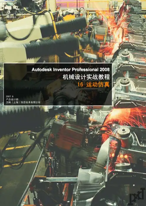
AUTODESKINVENTOR2024机械设计实战教程16运动仿真在AutoDesk Inventor 2024机械设计实战教程中,第16章主要介绍
了运动仿真的相关内容。
运动仿真在机械设计中起到了非常重要的作用,
可以帮助设计师更好地理解和分析机构运动的特性,从而改善设计,提高
设计的准确性和效率。
通过学习本章内容,读者可以了解到如何使用运动仿真工具对机械设
计进行分析和优化。
运动仿真可以帮助设计师更好地理解机构的运动特性,发现潜在问题,并提出相应的解决方案。
这对于改进设计、提高产品质量
和效率具有重要意义。
总之,AutoDesk Inventor 2024机械设计实战教程中的第16章对运
动仿真进行了详细介绍,并通过实例演示了如何使用运动仿真工具对机构
进行分析和优化。
通过学习本章内容,读者可以获得更深入的机械设计知
识和技能,提高设计的准确性和效率。
特别说明
此资料来自豆丁网(http://www.docin.com/)
您现在所看到的文档是使用下载器所生成的文档
此文档的原件位于
感谢您的支持
抱米花
http://blog.sina.com.cn/lotusbaob
http://www.docin.com/p-48186594.html