500W安装手册
- 格式:doc
- 大小:2.46 MB
- 文档页数:14

SSPI0-240000/500电力变压器安装使用说明书保定天威保变电气股份有限公司2004年4月目次1适用范围 (2)2产品使用的环境条件 (2)3主要技术参数 (2)4变压器电气接线原理图 (4)5出线套管位置 (4)6结构简介 (4)7变压器主体的起吊 (5)8运输 (5)9验收 (6)10存放 (6)11总体复装前的准备工作及要求 (8)12变压器现场安装前的检查项目 (13)13变压器附件、组件的安装 (15)14真空注油 (19)15补油 (20)16热油循环 (20)17静放及密封性试验 (20)18变压器外表面清理及补漆 (21)19变压器投运前的检查 (21)20变压器投运前的试验 (21)21变压器的运行与维妒 (22)1适用范围1.1本说明书仅适用于代号为IBB.710.901.l的电力变压器。
1.2本说明书中的内容只包括变压器本体部分,各组件有单独的安装使用说明书,其文件代号请查阅电力变压器《出厂技术文件目录》1BB.710.901.lCM。
产品在进行运输、安装、检修等工作项目之前,必须详细阅读本说明书及相关的组件安装使用说明书。
若在工作中涉及到上述说明书中还未详尽的内容或资料,请及时与我公司联系,避免由于不合理的操作引起设备损坏。
2产品使用的环境条件2.1海拔高度:≤1000m2.2最高气温:+40℃2.3最低气温:-25℃2.4最大日温差:21K2.5多年平均相对湿度:81%2.6最大风速:19m/s2.7日照强度:0.07W/cm2(风速0.5m/s)2.8最大积空深度:7cm2.9污秽等级:Ⅲ级2.10地震烈度:Ⅷ度2.11峰值加速度:0.23g2.12水温:25℃3主要技术参数3.1产品名称:电力变压器3.2产品型号:SSP10-240000/5003.3额定电压比:525/13.8kV3.4额定容量:240/240 MV A3.5额定频率:50Hz3.6相数:三相3.7调压方式:高压侧无励磁调压,调压范围525±2×2.5%kV3.8联结组标号:YNdl l3.9中性点接地方式:直接接地3.10冷却方式:ODWF3.11极性:负极性3.12空载损耗、负载损耗、短路阻抗、绕组直流电阻等参数实测值见产品合格证明书或变压器铭牌(8BB.860.3144)。

SVB500SpeedVault®Owner’s ManualPatented Rev 3 (04/14)WARNING: GunVault ® products or any other firear m storage device cannot take the place of other safetyprocedures; including advising children of the dangers of firearms.W ARNING: Never grab your firear m by the trigger w hen removing or placing it into your GunVault ® product. Alw aysmake sure your firearm’s safety mechanism is on.W ARNING: Alw ays follow the firearm safety rules set forth by the firearm’s manufacturer.W ARNING: In order to enjoy the maximum security benefits of the GunVault ® product, it must be secured in placeaccording to the instructions provided herein. Use of this product as a storage receptacle w ithout mounting according to the instructions provided herein may compromise security.Biometrics are methods of authenticating the identity of a person based on physiological or behavioral characteristics. Biometric fingerprint authentication refers to technology that measures and analyzes human physical characteristics for identification and authentication purposes.Everyone has their own individual fingerprints. The individuality of each fingerprint can be determined by the pattern of ridges and furrows on the surface of the finger as well as by the minutiae points. Minutiae points are local ridge characteristics that occur at either a ridge bifurcation or a ridge ending. A biometric device brings a higher level of security due to its personalized feature.The biometric scanner is sensitive and requires care not to damage the device. In addition, it is recommended that you practice the authentication process several times in order to become comfortable with the process.GunVault ® Tip : Locate keys and have them in a place you can easily access in emergencycases.(1) Mounting Bracket(2) Access Keys(4) Wood Screws (3) Thumb Screws (1) Zerust Strip “Rust Protection Technology”SAFETY INFORMATIONUNDERSTANDING BIOMETRICSITEMS INCLUDEDFor convenience, go to /warranty to fill out the warranty registration or call our Customer Service Department at 1(800)222-1055.Please fill out the section below and store in a safe location OUTSIDE of yourSpeedV ault®.M ODEL N UMBER____________________(T HIS CAN BE FOUND ON THE INSIDE ROOF OF THE UNIT.)S ERIAL N UMBER____________________(T HIS CAN BE FOUND UNDER THE MODEL NUMBER ON THE INSIDE ROOF OF THE UNIT.)K EY N UMBER____________________(T HIS CAN BE FOUND ENGRA VED INTO THE LOCK ITSELF)Mounting Positions:Using the provided bracket, theSpeedVault® Biometric can bemounted from the:∙Left∙Right∙Back∙TopUnit must be mounted at a 90︒ angle as the door is gravity operated.This information is necessary when ordering replacement keys or filing a warranty claim. Tools Needed:∙Phillips-Head Screw Driver∙Needle Nose Pliers∙9V Alkaline BatteryOptional Tools:∙Power Drill∙Phillips-Head BitGETTING STARTEDWARRANTYREGISTRATIONGunVault®Tip: For best performance, use a battery with expiration date 4 years out. We strongly advise to get name brand batteries and avoid lithium, duralock, & rechargeable batteries. Only use alkaline batteries.ZStep 1. Select a location to mount the unit.Step 2. Secure the “Mounting Bracket” to the desired locationusing the “Wall Mounting Holes” and the wood screws.Step 3. Keeping the unit closed, remove thumb screws at thebottom of the unit (use of pliers is recommended). After removing thumbscrews, remove the bracket.Step 4. Place the SpeedVault ® on a flat surface and use the keyto unlock the unit; Pull the drawer off separating it completely from the unit.Step 5. The battery tray is on the inside roof of the unit. Open thebattery tray door and insert new 9v Alkaline battery, following the Positive (+) and Negative (-) guides on the holder. Close the battery tray door when finished.Step 6. Align the shell of the unit to the “Mounting Bracket” usingthe “Hook Mounting Holes” as a guide . Secure using the 3 thumb screws turning them clockwise until tight.Step 7. Reinstall the drawer by replacing the bracket and two“Thumbscrews”.Step 8. The SpeedVault ® is now ready for use.Mounting screws provided are for solid wood surface only. If mounting to another surface type (drywall, cement, etc.) the appropriate hardware can be purchased through a local hardware store. Unit is sold at factory default and pressing the start button will open the unit. To change this, see Programing SpeedVault ®.The SpeedVault ® uses gravity to drop the drawer open and will need enough space in front of unit to fully open.INSTALLING THE SPEEDVAULT ®The SpeedVault ® Biometric can store 120 fingerprints with the first two enrolled fingerprints being the administrators. The administrator finger prints will be needed to program additional users. You will know you have reached themaximum 120 fingerprint enrollment if the Learn/Mute button is pressed and the LED flashes red once and the unit beeps once.Step 1.Press the Start button to open unit.Step 2. Press the Learn/Mute Button located next to the battery tray on the Inside roof of the unit (Unit will beep and flash green once, this indicates the enrollment procedure has started)Step 3. Place your finger over the scanner with the tip of your finger at the top of the finger guide.Step 4. Make sure you have good, flat contact with the scanner, taking 1 to 2 seconds to complete the swipe. A single beep will indicate a successful swipe and red flash indicates an unsuccessful swipe. Step 5. Repeat Step 3 until you hear a double beep which will indicate a successful enrollment of the fingerprint.Step 6.Repeat steps 1 through 5 to add the second administrator.GunVault ® Tip : A fingerprint scan can be sensitive to the angle in which you scan your fingerprint. Enroll the same finger 3-5 times at different angles to increase positive biometric access. During a high stress situation you will most likely not swipe your fingerprint the same way every time. Enroll your fingerprint in multiple angles and practice accessing your unit until you are comfortable.PROGRAMMING THE SPEEDVAULT ®ENROLLMENT OF THEADMINISTRATOR FINGERPRINTS GunVault® Tip : Your first two users enrolled are the administrators andare used to enroll additional users, use a finger on your non-dominate hand to reduce errors when enrolling additional users.Step 1.After enrolling the first two administrator fingerprints, open the unit using key or biometric scanner and press the Learn/Mute Button. Y ou will hear one beep and the LED will turn green indicating the enrollment procedure has started.Step 2. Swipe the administrator fingerprint from Position 1 to Position 2 and you will hear two beeps indicating the additional fingerprint is ready for enrollment.Step 3. Place the finger you want to enroll over the scanner with the tip of your finger at the top of the finger guide.Step 4.Make sure you have good, flat contact with the scanner. Begin to swipe your finger from Position 1 to Position 2, taking 1 to 2 seconds to complete the swipe. A single beep will indicate a successful swipe and red flash indicates an unsuccessful swipe.Step 5.Once the swipe is completed you will hear a beep. Repeat Step 3-4 until you hear a double beep this indicates a successful enrollment.Fingerprint AccessStep 1. Press the Start button; unit will flash green twice and beeponce.Step 2. Place a programed finger on the scanner with the tip of yourfinger at the top of the finger guide.Step 3. Make sure you have good, flat contact with the scanner. Beginto swipe your finger from Position 1 to Position 2, it will take 1 to 2 seconds to complete the swipe. Try to get your entire fingerprint to cross the scanner.Step 4. If the unit detects a match, the LED will flash green two timesand you will hear two beeps, then the unit is open.Step 5. If the unit doesn’t detect a match, the LED will flash green andred, you will be denied access. If an enrolled user is denied access, please try again.GunVault ® Tip : You go to the range and practice with your gun; practice accessing your gun with your GunVault as well. Practice will assure you have proper training to access your safe.ENROLLING ADDITIONAL USERSACCESSING THE UNITUSING THE KEY ACCESSStep 1. Insert the key into cylinder key hole on the unit.Step 2. Turn clockwise to unlock the unit. Door will drop open.Step 3. Turn the key counterclockwise to original position and remove.Low Battery Warning: If the LED flashes red and the unit beeps 3 times, this indicates a low battery .Step 1. Locate the battery tray on the inside roof of the unit. Step 2. Pull open the battery cover and remove the old battery.Step 3. Insert new 9v Alkaline battery, following the Positive (+) andNegative (-) guides on the holder.Step 4. Reinsert battery and snap the cover back into place. Step 5. T est your unit.Mute Feature: The audio can be turned off or on using the Mute feature.Step 1. Locate Learn/Mute button on the inside roof of the unit.Step 2. Press and hold the Learn/Mute button for three seconds. (threegreen LED flashes will mean you have successfully muted/unmuted your unit)Step 1. Locate Delete button on the inside roof of the unit.Step 2. Press and hold the Delete button (LED will turn red), press andrelease the Start button. (Unit will beep twice and flash green twice indicating you have successfully deleted all registered fingerprints.)∙ The key is for emergency use only to unlock the case in the event of fingerprint failure. ∙ Do not try to remove the key in any other position or this may cause damage.∙ Do not try to use the fingerprint scanner while the key is in the unit. Individual users cannot be deleted from the SpeedVault Biometric. All users will be deleted together.REPLACING THE BATTERY USING THE “MUTE” FEATURE DELETING USERS / RESETTING THE UNITTroubleshooting my SpeedVault® BiometricWhat is the problem? Why is the problemhappening? How do I solve the problem?When I swipe press the start button, unit beeps 3 times with 3 red flashes. Low battery indicator signalsit’s time for a battery changeReplace with 9V regularAlkaline battery. (Do not uselithium or rechargeablebatteries) (See PG. 6.)When I swipe my finger, I get one red flash. The unit did not recognizeyour fingerprint.Re-scan your fingerprint. Notethat the unit is sensitive toangles requires practice forfamiliarity. (See PG. 5)When I press the startbutton, the unit opens without scanningfingerprint. The safe has not beenprogramed properly.Follow ProgramingSpeedVault Instructions.(See PG. 4)The door does not open fully when I open theSpeedVault The SpeedVault was notmounted properlyFollow Installing SpeedVault®(See PG. 5)I need to order keys N/A Go to and mail in the Key Order form.What guns can fit into my SpeedVault®? N/AIt’s designed for full framedsemi-automatic pistols. (e.g.1911, Glock 19, Berreta 92)I can’t find the serialnumber. N/AThe serial number is on theinside roof of the unit next tothe battery tray.If you have followed the above steps carefully and still have a problem operating your SpeedV ault Biometric, call us at 800-222-1055 for further assistance. Requirements for Replacement & Repair∙Do not return your SpeedV ault Biometric safe to your dealer. Instead, call GunV ault T echnical Support Department for assistance 800-222-1055.∙GunV ault Inc. cannot provide refund for product.∙GunVault product delivered without a pre-arranged Return Authorization Number may be returned to sender unopened, at owner expense, and fees may accrueTECHNICAL SUPPORT1. GunVault (the “Company”) warrants to the or iginal consumer (the “Purchaser’) of any GunVault safe (the “GunV ault safe”)purchased after January 1, 2014 against any damage caused by fire, burglary or attempted burglary for a period of five (5) years from the date of purchase.2. The Company w arrants to the purchaser that the GunV ault safe w ill be free from defects in workmanship and materials for aperiod of one (1) year from the date of purchase.3. These warranties are not assignable or transferable to any other person.4. Any damage to the GunVault safe as a result of misuse, tamper ing, abuse, neglect, accident, impr oper installation, modificati on,unauthorized service, destruction, or the alteration of the serial number , or use violate of the instructions furnished by the Company will void this warranty.5. The sole responsibility of the Company shall be limited to the repair or replacement (in its sole discretion) of any componen t of theGunVault safe which fails to conform to this warranty at no cost to the purchaser for the period of the warranty.6. Contact the Company directly to obtain service under this warranty. If it becomes applicable to send a defective product to t heCompany, a Return Authorization Number must first be obtained from the company. In order to obtain service under this warranty, purchaser must provide the Company with the following items (a) proof of purchase, (b) police or fire department report, (c) photographs of damaged sad, and (d) written testimonial.7. Products shipped without prior Return Authorization and Return Author ization Number may not be accepted, and the Companywill not be responsible for their disposition and/or cost of return to the owner .8. The Company will not assume any responsibility for any loss or damage incurred in shipping. All return author ized productsshould include a copy of the original invoice in order that this warranty may be honored.9. This warranty is not an insurance policy. The C ompany is not responsible for any manner of damage to or theft of the Purchaser’sGunVault safe or its contents.10. We recommend that the enclosed warranty cared be completed in full, and returned to the Company within ten (10) days of theoriginal date of purchase to validate this warranty.11. Any implied warranties that the purchaser may have are limited to the duration of the warranties described above. There are nofurther w arranties that extend or apply beyond the face hereof, and the company expressly disclaims and excludes any and all w arranties of merchant ability or fitness for a particular purpose. Some states do not allow limitations on how long an implied warranty lasts, so the above limitation may not apply to you.12. R epair or replacement shall be the sole remedy for the purchaser under this warranty. The company shall not be liable for anydirect, indirect, incidental or consequential damages, losses or expense ar ising from the use or misuse of the GunVault safe. Some states do not allow the exclusion or limitations of incidental or consequential damages, so the limitation may not apply to you.13.This warranty gives you specific legal rights, and you may also have other rights wh ich vary from state to state.®including advising children of the dangers of firearms.W ARNING: The manufactur ers and distributors of the SpeedVault ®Biometr ic safe do not recommend, suggest, advise, promote orotherwise condone the ownership or use of firearms. We at GunVault ® Inc. believe the decision to own or use a firear m is a serious decision that should only be made by an adult who has carefully considered the r isks and benefits of such a decision.W ARNING : The keypad and push buttons on the contr ol panel are electronic. They have a certain feel to them and may seemdifferent to different people. It is important for you to become accustomed through practice, as to how the SpeedVault ® Biometric safe responds to your own personal touch.W ARNING: Never mix alcohol or drugs with firearms or the SpeedVault ® Biometric safe. Alcohol and other substances likely toimpair nor mal mental or physical functions should not be used before shooting or handling firearms or the SpeedVault ® Biometric safe.W ARNING: Never grab your firear m by the trigger w hen removing or placing into the SpeedVault ®Biometr ic safe. Make sure yourfirearm’s safety mechanism is on.W ARNING: Always point your firearm in a safe direction. Common sense should dictate which direction is the safest.W ARNING: Always follow the firearm safety rules set out by the firearm’s manufacturer .W ARNING: Be familiar with h ow firear ms work. GunVault ® recommends that you obtain as much infor mation as possible on firear msafety.W ARNING: Always handle firearms as if they are loaded and ready to fire. Always assume that a firearm is loaded.W ARNING: In order to enjoy the maximum security benefits of the SpeedV ault ® Biometr ic safe product, it must be mounted in placeusing the equipment provided w ith the product, according to the instructions provided her ein. Use of this product as a storagereceptacle without mounting according to the instructions provided herein may compromise secur ity of the SpeedVault ®Biometric Safe.We recommend that the warranty registration be completed in f ull and submitted to GunVault ®Inc. within thirty (30) days of the original date of purchase to validate this warranty. You can complete your warranty registration by visiting our website at /warranty or calling our Customer Service department at 800-222-1055LIMITED WARRANTYSAFETY INFORMATIONInquiries or questions regarding the SpeedV ault®Biometric should be directed to:GunVault®, Inc. Support LinkTechnical Support 800-222-1055Protected by United States Patent Numbers5,161,396 and 5,549,337。

供电承装公司变电工程项目部隔离开关现场安装作业指导书共 15 页产品型号 GW17-550DW 状态受控产品名称高压户外隔离开关已审核批准1.范围本指导书合用于 GW17-550DW 高压隔离开关的现场安装与调整。
2.引用文件本指导书引用了如下有效文件,当本指导书未描述或者对其有疑惑时,使用本指导书的有关人员均应查阅和执行下列文件。
平顶山高压开关厂的安装使用说明书。
14-B1001S-D0103 DT/5161.2—2002 GBJ147-90 卷册设计图纸。
质量检验标准第五部份。
第八章隔离开关施工验收规范。
3.现场装配前注意事项3.1 施工前,所有参预施工的人员均要接受本指导书的交底。
3.2 装配过程应随时记录有关施工记录。
3.3 现场开箱后,应即将检查其型号、规格是否与设计相符,特殊注意额定电流、电压等有关参数。
3.4 检查绝缘子有无裂纹、破损,瓷铁结合处是否坚固无松动。
3.5 导电杆、触头有无变形。
3.6 子细核对零配件是否齐全。
3.7 本指导书中数据单位除注明外,均为mm4.装配程序 (见下页)第 1 页供电承装公司变电工程项目部隔离开关现场安装作业指导书共 15 页产品型号 GW17-550DW 状态受控产品名称高压户外隔离开关已审核批准到货验收检查测量支架水平度及距离开箱检查技术交底及工作票基座安装调整主体安装操作机构安装相间、机构及零配件安装N 机械性能调整Y检查和试验二次接线一次端子接线接地线安装交接、投运第 2 页供电承装公司变电工程项目部隔离开关现场安装作业指导书共 15 页产品型号 GW17-550DW 状态受控产品名称高压户外隔离开关已审核批准5 隔离开关的有关参数5.1 有关电气参数额定电压 kV 500最高电压 kV 550额定频率 HZ 50额定电流 A 3150额定峰值耐受电流 KA 1253S 短时耐受电流 KA 50隔离开关主回路电阻μ Ω 不大于 130接地刀主回路电阻μ Ω 不大于 130隔离开关分闸后最小绝缘距离 m 4.7接地刀闸分闸后最小绝缘距离 m 4.0合闸后动触头最小夹紧力 N 不小于 1205.2 安装过程螺栓的拧紧力矩:M8 20Nm M10 40NmM12 70Nm M16 170NmM20 340Nm M24 600Nm 5.3 所配电动机构技术参数输出角度:分闸一次时间:合闸一次时间: 机电转速:电机电压:控制回路电压: 90 ±4° (可调)9±2s9±2s1400r/minAC380V220V第 3 页供电承装公司变电工程项目部安装内容隔离开关现场安装作业指导书第 4 页共 15 页产品型号 GW17-500W 状态受控产品名称高压户外隔离开关已审核批准简图备注6 安装过程6.1 基础检查按右图 1 检查基础的水平尺寸,误差不超过 5mm 。

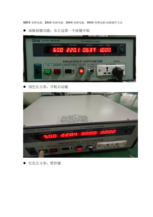
500W变频电源,1KVA变频电源,2KVA变频电源,3KVA变频电源-面板操作方法●面板按键功能:从左边第一个按键开始●绿色长方形:开机启动键●红色长方形:暂停键●指拔式按键:输出频率调节键●正方形红色:高低档(按下灯亮为高档,在按下灯不亮为低档)●旋钮数字:电压输出调节键●手指插座说明:此插座为输出电压插座500W变频电源,1KVA变频电源,2KVA变频电源,3KVA变频电源-技术参数1KVA变频电源技术参数(OYHS-9801)产品共同特点输出电压:0-300V连续可调输出频率:60HZ,50HZ,40-499.9HZ连续可调超臷能力强,瞬间电流可承受三倍额定电流故障时一键停机功能,反应速度快,反应时间在2ms以内具有过流,过压,过温,短路,过载等多重保护及报警功能高精度的稳频稳压功能,快速调节电压,频率主要元器件均采用原装进口品牌,品质可靠单进单出变频电源技术参数型号:OYHS-98005(输出功率500W)型号:OYHS-9801(输出功率1KVA)型号:OYHS-9802(输出功率2KVA)型号:OYHS-9803(输出功率3KVA)电路方式IGBT/SPWM脉宽调制方式交流输入相数单相波形SINEWAWE电压220V±10%频率波动范围50HZ or60HZ±5%功率因数﹥0.9交流输出相数单相波形SINE WAVE低档电压0-150V连续可调高档电压0-300V连续可调频率60HZ,50HZ,40-499.9HZ连续可调频率稳定率≤0.01%低档最大电流(A)电压在0-150V时500W(4.2A),1KVA(8.4A),2KVA(16.8A),3KVA(25A)高档最大电流(A)电压在150-300V时500W(2.1A),1KVA(4.2A),2KVA(8.4A,3KVA(12.5)整机性能电源稳压率﹤1%负载稳压率﹤1%波形失真度﹤1%效率﹥90%反应时间≤2ms波峰因子3:1保护装置具有过压,过流,超载,输入欠压,过高温,短路等多重保护显示显示介面数位式LED显示电压4位数,数位电压表,解析度0.1V电流4位数,数位电流表,解析度0.1A功率4位数,数位瓦特表频率4位数,数位频率表环境及其它冷却装置高速变频风扇冷却,强制冷风工作温度-10℃to50℃相对湿度0~90%(非凝结状态)海拔高度≤1500m重量(KG)21,23,45,60尺寸(H*D*W)mm180*500*430注:1以上尺寸不含脚输高度2可根据顾客要求规格特别定制3本公司产品规格不断研发改进,规格若有变更,恕不另行通知。

通用功率扩展器 200-500 W/VA订货号 : 1035 00使用说明1 安全指南电气设备的安装和装配只允许由电气专业人员执行。
可能引发严重伤害、火灾或财物损失。
请完整阅读并遵守操作说明。
电击危险。
设备不应断开。
即使在关闭仪器的情况下,负载也没有断开电源。
电击危险。
在对设备或负载施工前先安全断开。
对此需注意为设备或负载供应危险电压的所有线路保护开关。
火险。
在使用感应变压器操作时,必须遵守每种变压器相应制造商的使用说明。
只能使用符合EN 61558-2-6(VDE 0570,第 2-6 部分)的安全隔离变压器。
在隔离变压器网上运行时,功率至少为 10 kVA。
否则无法保证调光器能够正确识别与负载相符的调光原理。
设备也会受到损害。
该说明书属于产品的组成部分,必须由最终用户妥善保管。
2 设备结构图像 1: 设备结构(1)功率放大器3 功能正常应用-参考列表(参见技术数据一章)中所述的 Tronic 或通用调光器的功率扩展-接通高压白炽灯、高压卤素灯以及使用 Tronic 变压器或可调光感应式变压器的卤素灯,并进行调光-适合于指定总功率以下的混合运行(参见技术数据一章)-按照 DIN EN 60715 安装至配电箱中的支承轨道上i功率超过 1000 W/VA 的照明设备涉及到专业化的应用状况。
i非 Tronic 变压器和感应式变压器的混合运行。
i无法运行高压 LED 灯。
产品特性-多个功率放大器与一台调光器的连接-相连负载的总功率分配给调光器和功率放大器-通过共用负载线为相连的负载供电-通过上游连接的调光器进行操作-电子超温保护i通过低于给定最小负荷或通过发电厂集控脉冲信号可以使连接的灯具亮起。
这并不是设备的缺陷。
i没有功率放大器的调光器上的照明和使用功率放大器的调光器上的照明可能在亮度上有所不同。
4 电气专业人员信息4.1 安装和电气连接危险!接触导电部件可能导致触电。
触电可能导致死亡。
用户操作使用说明书感谢你使用本司产品,请在使用产品之前详读产品的应用说明:重要指引1. 使用设备前请阅读所有的文件,并保留所有的文件以作进一步参考。
2. 必须使用与背板标称电压相符的电源,若由于使用电压的不恰当而导致的设备损坏将不获保修。
3. 设备的地线和使用电源的地线必须连接到一起,并要确认使用电源的地线是真实的与大地连接的地线。
4. 禁止功放在桥接状态下输出端和示波器的探头相连,否则对功放及测试设备都会造成损害。
5. 功放的输入电平不要超过标称的灵敏度值。
6. 不要将功放的某一个声道的输出接到另一个通道的输入。
不要将功放的输出并联或串联到另一台功放的输出使用。
7. 配置功放的时候,功放的功率必须比音箱的标称功率大50%-100%。
8. 必须确认功放当前的使用状态和输入模式的设置一致。
9. 在拔掉电源线、信号线、拨动输入模式选择开关、限幅器开关,灵敏度开关前必须先把功放电源关掉。
10.功放的音量旋钮通常设到0dB处。
11.在一个信号要分给多台功放使用的情况,建议使用信号分配器进行搭配。
12.不要将功放的进风口,出风口堵塞。
安全注意事项:在开始使用功放前请仔细阅读此安全指引。
安装设备时:-- 必须在平坦的地方安装,不能倒放功放。
-- 不能在有水或潮湿的地方安装。
-- 将功放远离热源,如辐射体或其他热源。
-- 请不要将其它物品置于机身顶盖上。
在连接功放时请记住:-- 在连接功放前请仔细阅读本手册。
-- 请仔细连接功放的每个接口。
否则,有可能会由于线路断开而导致噪声、出现故障或电击等现象。
-- 为避免电击,请不要打开顶盖。
检查交流电源符合额定值后,才能将电源线连接致电源插座上概述1 本设备的功率管采用了不等距的排列方式,有效利用散热器,使得产品的散热效率更高;2 使用了全新的并联+隧道式风冷散热系统,使得产品的散热效率更高,整机的工作温度更低,产品的稳定性、可靠性更高;更低,产品的稳定性、可靠性更高;4 先进的保护功能,输出方式比传统得到更高的阻尼系数;完善的可靠性保护功能:本产品有完善的可靠性保护措施,这些保护既可保护功放自身不受损坏,有可以保护与之连接的喇叭系统。
1GST-GF500WA/300WA/150WA 型广播功率放大器安装使用说明书特点广播功率放大器是消防应急广播系统配套产品,它与相应的广播音源设备和广播终端设备等配合,实现消防现场的应急广播功能。
GST-GF500WA 型广播功率放大器、GST-GF300WA 型广播功率放大器、GST-GF150WA 型广播功率放大器功能相同,但功率不同,分别为500W、300W 和150W。
主要技术指标(1)工作电压:主电源交流AC220V,备用电源交流AC220V(2)定压输出:120V(3)频率特性:80Hz~8KHz (90V~145V)(4)输出功率:500W/300W/150W(5)谐波失真:≤5%(6)噪声电平:<37mV(7)使用环境:温度:0℃~+40℃相对湿度≤95%,不结露(8)外形尺寸:88.1mm(2U)×482.6mm×305.0mm结构特征与安装以GST-GF500WA 型广播功率放大器为例进行说明,其外形及结构示意图如图图-1-2本广播功率放大器采用标准插盘结构安装,其后部示意图如图图2-21)工作指示灯:200A启动本设备后该指示灯为绿色,表示本机工作正常。
说明:当功放电源开关打开时工作指示灯不亮,此时如果主备电均正常时,主电绿灯亮,说明功放处于待机状态。
2)故障灯:说明:故障灯常亮,表示本机音频输出线处于交流短路,本机已经处于保护状态。
如果音频输出线短路故障排除,需将电源关闭,然后再重新启动,才能解除指示灯常亮状态;23)主电指示灯:绿灯亮表示本机采用主用电源供电,黄灯故障灯亮说明主用电源断开。
说明:当功放电源开关打开时,如果主电正常则绿灯点亮,如果断开则黄灯点亮。
4)备电指示灯:绿灯亮表示本机采用备用电源供电,黄灯故障灯亮说明备电断开。
说明:当功放电源开关打开时,如果主备用电源均正常,默认主电优先工作,对应主电指示灯为绿色,备电指示灯处于熄灭状态(代表目前备电正常);如果主用电断开,功放会自动转为备用电工作,对应的备电指示灯为绿色,主电指示灯为黄色。
INSTALLATION MANUAL ANDOPERATING INSTRUCTIONSTI500-( ) SeriesStatic Electrical Power InverterTrue Blue Power® is a division of Mid-Continent Instrument Co., Inc.Mid-Continent Instrument Co., Inc.dba Mid-Continent Instruments and Avionics9400 E. 34th Street N. Manual number 9017039Wichita, KS 67226 Rev E, August 29, 2012FOREWORDThis manual provides information intended for use by persons who, in accordance with current regulatory requirements, are qualified to install this equipment. If further information is required, please contact:True Blue Powerc/o Mid-Continent Instrument Co., Inc.Attn: Customer Service Dept.9400 E. 34th St. N.Wichita, KS 67226 USAPhone 316-630-0101Fax 316-630-0723We welcome your comments concerning this manual. Although every effort has been made to keep it free of errors, some may occur. When reporting a specific problem, please describe it briefly and include the manual part number, the paragraph/figure/table number, and the page number. Send your comments to:True Blue Powerc/o Mid-Continent Instrument Co., Inc.Attn: Technical Publications9400 E. 34th St. N.Wichita, KS 67226 USAPhone 316-630-0101Fax 316-630-0723©Copyright 2012Mid-Continent Instrument Co., Inc.REVISION DETAILRev. Date Approved Detailrelease.A 02/26/10 BAW/JRC InitialB 07/06/10 BAW/MKN Update Section 2.4 to add limitation statement regarding output.C 07/20/10 MKN/BAW Update unit picture with True Blue Power label.D 02/24/11 JDS/BAW Added section 3.3.2, and figure 3.4.E 08/29/12 BMC/JDS Model name changed to TI500.TABLE OF CONTENTSSECTION 1 GENERAL DESCRIPTION1.1INTRODUCTION1.2TECHNICAL SPECIFICATIONS1.2.1ELECTRICAL ATTRIBUTES1.2.2PHYSICAL ATTRIBUTES1.2.3QUALIFICATIONSSECTION 2INSTALLATION CONSIDERATIONS2.1COOLING2.2EQUIPMENT LOCATION2.3ROUTING OF CABLES2.4LIMITATIONSSECTION 3INSTALLATION PROCEDURE3.1GENERAL INFORMATION3.2UNPACKING AND INSPECTING3.3CABLE HARNESS3.3.1WIRE GAUGE SELECTION3.3.2PIN ASSIGNMENT INFORMATION3.3.3HARNESS VERIFICATION3.4MOUNTING3.5INSTALLATION COMPLETIONSECTION 4OPERATION4.1ELECTRICAL PERFORMANCE4.2PROTECTIVE FEATURESSECTION 5CONFORMANCE5.1CONTINUED AIRWORTHINESS STATEMENT5.2ENVIRONMENTAL QUALIFICATION STATEMENT NUMBER LIST OF TABLES AND FIGURESTABLE1.1 MODELS1.2 PHYSICAL ATTRIBUTES TABLETABLE1.3 PERFORMANCEFIGUREPINOUT3.3 CONNECTOR3.3 CONNECTOR PINOUT TABLEDIAGRAMS3.4 EXAMPLEWIRING3.5 TI500 OUTLINE DRAWING FIGURE3.6 TI500 MOUNTING ADAPTER FIGUREPERFORMANCE4.1 THDSECTION 1GENERAL DESCRIPTION1.1INTRODUCTIONThe model TI500 series Static Electrical Power Inverter is a lightweight power converter that translates a 20 to 36 VDC input to a 115 VAC output at 60 Hertz and provides 500 watts (VA) of power. The alternating current output is defined as a pure sine wave with less than 3% of total harmonic distortion for clean, noise-free, harmonic-free power to supply nearly any common commercial or consumer load rated for a nominal input of 115VAC. The TI500 series Inverter, part number MD50-( ), is FAA certified to TSO C73 and tested to rigorous environmental standards and levels of RTCA DO-160. The small size and light weight in conjunction with its installation flexibility inside or outside the pressure vessel make it an ideal choice for aircraft power needs while reducing the challenges associated with other similar products. Highlighted features include short circuit protection, overload capability, low voltage shut-down, temperature monitoring, a self-resettable over-temperature disable, and a remote on/off function. The rugged extrusion that houses the unit is designed to help dissipate heat and provide mechanical strength against vibration or other possibilities of damage. Two independent fans allow for a smaller unit and provide a quieter operation while keeping the internal components cool and extending the life of the unit.1.2TECHNICAL SPECIFICATIONS1.2.1ELECTRICAL ATTRIBUTESCharacteristics:Input Voltage: Rated 28VDC nominal; 20-36VDC certifiedInput Power: 17-25 amps; 0.2A at no loadOutput Voltage: 115VAC ±3% at 60 Hertz ±0.1% (single phase)Output Power: 500 watts (500 VA at power factor = 1)Output Waveform: Pure sine wavePower Factor: -0.8 to +0.8Efficiency: 88%nominalTotal Harmonic Distortion (THD): < 3%; See Figure 4.1Table 1.11.2.2PHYSICAL ATTRIBUTESCharacteristics:Weight: 3.9poundsDimensions:(not including connector mate) 6.71 inches long (8.15 inches – mounting base) 6.34 inches wide2.74 inches highMating Connector (and cable clamp): MS3106A-18-9S or equivalent (MCI P/N 9016905-1 and -2) Mounting: Base mount – orientation not criticalTable 1.21.2.3QUALIFICATIONSSpecifications:Qualification: FAATSO-C73 Environmental Qualification: RTCA DO-160F Environmental CategoryF3(Y)S2BB(RCC1)XXXXXXZXXXXXBXXXXXAltitude: -15,000 ft to +55,000 ftTemperature: -55°C to +70°C (-67°F to +158°F); See Figure 4.2SECTION 2PRE-INSTALLATION CONSIDERATIONS2.1COOLINGNo external cooling is required. The unit is equipped with two internal brushless DC fans. Restriction to airflow can cause overheating of the unit and limit performance or reduce the expected life of the product. Make sure to provide adequate clearance on both ends of the unit with the hexagonal openings to allow for proper circulation. In general, four to six inches of clearance on both ends of the unit should be acceptable. Mounting the unit to a metal surface can also help reduce the effects of temperature within the unit but is not required.2.2EQUIPMENT LOCATIONThe TI500 Static Inverter is designed for mounting flexibility, allowing for installation inside or outside the pressure vessel with no requirement for temperature control. In addition to altitude and temperature resistance, the unit is also designed to withstand high levels of condensing humidity. However, installation locations where the unit could be subject to standing or direct water exposure should be avoided. The unit can be mounted in any orientation. Clearance should be provided for the mating connector and may require as much as four to five inches past the unit connector to allow for the backshell, access to the connector, and appropriate wire bends.2.3ROUTING OF CABLESThe wires and cable bundle associated with the unit are heavy gauge wire and carry significant power. Be aware of routing cables near other electronics or with other wire bundles that may be susceptible to high energy flow.Avoid sharp bends in cabling and routing near aircraft control cables. Also avoid proximity and contact with aircraft structures, avionics equipment, or other obstructions that could chafe wires during flight and cause undesirable effects.2.4LIMITATIONSThe TI500-( ) Series of static electric power inverters is certified to FAA TSO-C73 with the following limitations identified:1)Alternating current (AC) output is provided at 115 volts and 60 hertz in lieu of 115 volts and 400hertz as identified in the MPS of the TSO.2)Equivalent environmental qualification was verified per RTCA DO-160F in lieu of those identifiedwithin the MPS of the TSO.The conditions and tests for TSO approval of this article are minimum performance standards. Those installing this article, on or in a specific type or class of aircraft, must determine that the aircraft installation conditions are within the TSO standards, specification of the article, and deviations as listed above. TSO articles must have separate approval for installation in an aircraft. The article may be installed only according to 14 CFR part 43 or the applicable airworthiness requirements.SECTION 3INSTALLATION PROCEDURES3.1GENERAL INFORMATIONThis section contains interconnect diagrams, mounting dimensions and other information pertaining tothe installation of the TI500 Static Inverter. After installation of cabling and before installation of the equipment, ensure that power is applied only to the pins specified in the interconnect diagram.3.2UNPACKING AND INSPECTING EQUIPMENTWhen unpacking this equipment, make a visual inspection for evidence of any damage that may have incurred during shipment. The following parts should be included:a.Static Inverter – MCI P/N MD50 [or MD50-( )]b.Mating Connector (& cable clamp) – MCI P/N 9016905-1 (and 9016905-2)c.Installation Manual – MCI P/N 9017039Optional equipment available:a.Mounting Adapter Kit – MCI P/N 9017040Equipment not provided:a.Mounting Hardware – four (4) #10-32 pan head screws#10 lock washers (optional)b.Cable Harness Wire – See Section 3.3 for specification3.3CABLE HARNESSConstruct the cable harness with regards to the instructions below, and using the Connector Pinout of Figure 3.3, Figure 3.4, and Wiring Diagram of Table 3.3.Refer to Section 2: Pre-Installation Considerations in regards to routing precautions.3.3.1WIRE GAUGE SELECTIONUse of PTFE, ETFE, TFE, Teflon, or tefzel insulated wire is recommended for aircraft use. Usethe following wire gauges for each of the pins in the connector:Pin A and D – 12 AWG stranded or solidPin B and C – 16 AWG stranded or solidPin E and G – 16-24 AWG stranded or solid3.3.2PIN ASSIGNMENT INFORMATIONINPUT POWER:Pin A – Positive DC input +24 to 32 VDC. Connect to the aircraft 28 VDC bus using a 25 or30 Amp circuit breaker.Pin D – Negative DC input. Internally this pin is connected to the inverter enclosure. Connectto aircraft ground.INVERTER OUPUT :Pin B – AC Output 115VAC, 60Hz. Used for powering devices where terrestrial/utility power designations are used, pin B can be connected as “Line” or “Hot”.Pin C – AC Return 115VAC, 60Hz. Used for powering devices where terrestrial/utility power designations are used, pin C can be connected as “Neutral”.Note: Use of a circuit breaker on the AC output is optional. For the fullinverter 500VA output, a 5 Amp circuit breaker is sufficient. For convenience at each AC outlet, individual circuit breakers of 1 to 2 amps each can be used. If a single pole breaker is used, install the breaker on the wire from pin B. If a double pole breaker is installed, route both pins B and C through the circuit breaker.REMOTE ON/OFF CONTROL: (see section 4.2.1)Pin E – Remote ON/OFF Control. Connecting this pin to either DC Negative or to inverter pin G will enable the AC output of the inverter. By utilizing a switch between this pin and ground or negative, it will allow remote on/off control of the unit. When unconnected (output is OFF) this pin will have approximately 11 VDC present, internally limited to less than 1 mA. If the inverter is to be enabled at all times, pin E can be connected to pin G.Pin G – Remote ON/OFF Return. This pin is internally connected to pin D and the enclosure. Pin G can be used as the return from an ON/OFF switch or left unconnected. It is recommended that pin G not be connected directly to ground or 28V negative. Pin F – Reserved. Do not use.FIGURE 3.3 TABLE 3.3 PINOUT VIEW OF CONNECTOR PINOUTUNIT CONNECTORAD BE CF GTI500A 28VDC28VDCTI50030A30A3rd Partyequipment AA A(not supplied)110VAC Outlet(s)(not supplied)Ground Fault Indicator(not supplied)Notes:1. Wiring diagrams above represent various examples of typical installations.2. Recommended to attach case to metal aircraft structure.3. Recommended outlet protection may consist of either:A. single 5A circuit breaker for all outlet(s) (single or double pole breaker), ORB. 1-2A circuit breakers for each outlet4. For Remote On/Off operation, return line can be configured in one of three ways:1. return line connected to pin G2. return line connceted to pin D3. return line connected to aircraft ground3.3.3HARNESS VERIFICATIONWith the TI500 Static Inverter disconnected, activate the aircraft power bus that supplies theunit and use an multi-meter to verify that aircraft power and ground with appropriate voltageis on the pins within the mating harness.3.4MOUNTINGRefer to Section 2: Pre-Installation Considerations in regards to equipment location.The TI500 Static Inverter is designed for base mounting only. Four #10-32 mounting holes should be provided in the aircraft in accordance with Figure 3.5. If installing the TI500 as a replacement for legacy static inverters, an optional Mounting Adapter Kit adapter plate is available to utilize the same mounting hole locations. See figure 3.6 for mounting hole locations using the Mounting Adapter Kit and Section 3.2 for the Mounting Adapter Kit part number. Secure the unit with four #10-32 pan head phillips screws or equivalent. A lock washer under the head of each screw is recommended.3.5INSTALLATION COMPLETIONPrior to operating the unit in the aircraft, it is recommended to verify the output and functionality of the unit. In order to prevent accidental damage to other systems, it is best not attach the output to other equipment or power busses prior to verification. Verify the output of the unit at the terminating end of the cable with a multimeter to ensure proper voltage and polarity. Once verified, installation can be completed and functionality of the remote on/off feature (if used) should be checked.FIGURE 3.5TI500 OUTLINE DRAWINGFIGURE 3.6TI500 MOUNTING ADAPTERSECTION 4 OPERATION4.1 ELECTRICAL PERFORMANCEThe TI500 series Static Inverter converts a direct current (DC) voltage input to a regulated 115 volt alternating current (VAC) output. The output is controlled to a frequency of 60 Hertz and represents a pure sine wave with minimal distortion. The unit is capable of providing 500 watts to power a variety of aircraft accessories including laptops, personal electronics, onboard systems, and many others. (See Section 1.2.1 for tolerance ranges)The unit is designed as a two-stage, solid-state switch-mode power supply. The power transformation utilizes a first-stage push-pull methodology followed by an H-bridge AC forming second stage. The primary stage utilizes ‘current-mode’ control providing instantaneous load protection as an advantage over legacy designs that incorporate ‘voltage-mode’ controllers. The alternating current is frequencycontrolled using a crystal oscillator reference. Figure 4.1 Total Harmonic Distortion Performance vs Load Figure 4.2 Output Power Performance vs Temperature0.000.501.001.502.002.500200400600800T H D %output power (watts)100200300400500600‐60‐202060100o u t p u t p o w e r (w a t t s )temperature (°C)4.2PROTECTIVE FEATURES4.2.1REMOTE ON/OFFThe TI500 series Static Inverter incorporates a remote on/off feature that allows the user toenable or disable the output of the unit. By providing a ground on the appropriate pin (SeeTable 3.3) the user, via a remote mounted switch or similar method, can enable the outputof the unit. The unit can be similarly disabled by removing the ground signal (open circuit) tothe same pin.4.2.2OVER-VOLTAGEWhen the input voltage exceeds the operating range of the unit (See Section 1.2.1; absolutemaximum input of 37VDC) the unit senses an over-voltage condition and disables the output.The unit will dynamically monitor the input voltage such that if the input returns to within thenormal operating range, the output will be enabled and allow the unit to operate normally.4.2.3UNDER-VOLTAGEWhen the input voltage drops below the operating range of the unit (See Section 1.2.1;absolute minimum input of 20VDC) the unit senses an under-voltage condition and disablesthe output. The unit will dynamically monitor the input voltage such that if the input returnsto within the normal operating range, the output will be enabled and allow the unit tooperate normally.4.2.4OVER-TEMPERATUREThe TI500 incorporates an internal temperature sensing device that continually providesmonitoring and feedback to the control circuits. When the unit senses an internal conditionthat exceeds maximum temperature ratings, the output is disabled. The internal cooling fanswill continue to operate and the unit output will be enabled when the temperature returns towithin acceptable limits. This over-temperature reset occurs automatically without externalintervention required.4.2.5SHORT CIRCUIT AND OVER-CURRENTThe TI500 is capable of surviving a short circuit or over-current event without permanentdamage or effect to long-term reliability. The unit can provide over its rated power output upto 550 watts for up to 2 hours. The unit is also capable of supporting an overload conditionof 750 watts for 5 minutes with distortion of the sine wave and reduced voltage output.The unit monitors on pulse-by-pulse scenario to determine a short circuit or over-currentsituation. If detected, the output is limited by clipping the AC sine wave form, limiting thepower output. The unit will also produce an audible clicking noise, indicating that the poweroutput limit has been exceeded. When the short circuit or over-current event is removed, theunit will return to normal operation.4.2.6TEMPERATURE REGULATED COOLINGThe unit is equipped with two internal brushless DC fans for cooling to extend the powerrange and long-term life. The fans are activated at a specified point determined by thecontinuous monitoring of the internal temperature. The fans operate very quietly to reducethe audible noise in any environment. The two fans provide independent redundancy forprotection of the unit in the event that one becomes inoperative.The unit is also designed to provide 75% of the rated load continuously at temperatures upto +40°C in the event that both fans become inoperable and no cooling is available.SECTION 5 CONFORMANCE 5.1 CONTINUED AIRWORTHINESS STATEMENT No periodic scheduled maintenance or calibration is necessary for continued airworthiness of the TI500 series Static Inverter. If the unit fails to perform to specifications, the unit must be removed and serviced by Mid-Continent Instruments and Avionics or their authorized designee.5.2 ENVIRONMENTAL QUALIFICATION STATEMENT NOMENCLATURE: Static Electrical Power Inverter MODEL NUMBER: MD50-( ) TSO NUMBER: C73 MANUFACTURERS SPECIFICATIONS: Minimum Performance Specifications: Test Specification (TS) 445, Test Data Sheet (TDS) 445 QUALIFICATION STANDARD: RTCA DO-160FCONDITIONS SECTION DESCRIPTION OF TESTTemperature and Altitude Low Temperature High Temperature In-Flight Loss of Cooling Decompression Overpressure 4 4.5.1 4.5.2 4.5.5 4.6.2 4.6.3 Category F3(Y) Operating Low Temp = -55C Operating High Temp = +70C Category Y = 300 minutes, +40C, 75% Altitude = +55,000 ft -15,000 ftTemperature Variation 5 Category S2Humidity 6 Category B Operational Shock and Crash Safety7 Category B Vibration 8 Category R, Curve C, C1(RCC1)Explosion 9 Category X Waterproofness 10 Category XFluids 11 Category X Sand and Dust 12 Category XFungus 13 Category X Salt Spray 14 Category XMagnetic Effect 15 Category ZPower Input 16 Category XVoltage Spike 17 Category XAudio Frequency Conducted Susceptibility18 Category X Induced Signal Susceptibility 19 Category XRadio Frequency Susceptibility 20Category X Emission of Radio Freq Energy 21 Category BLightning Induced Transient Susceptibility22 Category X Lightning Direct Effects 23 Category XIcing 24 Category X ESD 25 Category X Flammability 26 Category X。
BZ PRODUCTS, INC.INSTALLATION MANUAL VERSION 1.0MODEL MPPT 500CURRENT BOOSTING MAXIMUM POWER POINT SOLAR CHARGE CONTROL READ ALL INSTRUCTIONS PRIOR TO INSTALLING OR USING THIS EQUIPMENT.SAFETY INSTRUCTIONS: Refer service to qualified service personal. Incorrect installation may result in risk of fire. Remove all sources of electrical power, photovoltaic and battery before servicing this equipment. Never charge a frozen battery. Warning! Batteries produce explosive gasses. Install batteries in a well ventilated area. Follow battery manufacture maintenance and charging recommendations. Install properly rated fuses as required. Do not connect controller to generators or alternators.DESCRIPTION: The model MPPT 500 is high performance current boosting solar control. Through the use of advanced microprocessor control and high efficiency power converter, power wasted in older PWM style solar controls is converted into higher charge current. The MPPT 500 allows for input voltage conversion. This increases the Maximum Power Point voltage and allows for higher boost current over wider operating conditions.A high accuracy digital volt and amp meter displays battery voltage, photovoltaic current and battery charge current. Proper battery charging is maintained over a wide temperature range with the battery temperature sensor. Battery float voltage is accurately regulated. Night time battery discharge is eliminated through the use of a high efficiency Scotkey diode. Maximum input power to the MPPT 500 is 500 watts. Maximum photovoltaic input voltage is 100 VDC open circuit.OPERATION: During operation the MPPT 500 may feel warm. Operation of the MPPT 500 is fully automatic. No adjustments are required for most installations. When power is available from the solar panel, the MPPT 500 microprocessor measures and determines the optimum operating point of the solar panel to produce the highest charge current possible to the battery. There is no interaction between the MPPT 500 and other battery charging systems.The float voltage of the MPPT 500 is calibrated to 14.1 volts. When the battery voltage reaches 14.1 volts the red Float LED turns on. At this point, charge current to the battery will gradually diminish to maintain the 14.1 float voltage. As soon a load is turned on, maximum charge current is applied to the battery. Temperature compensation adjusts the float voltage to properly charge the battery over a wide temperature range. When the battery is warm the float voltage will drop and when the battery is cold the float voltage will rise. MPPT 500 is well suited for flooded, deep cycle and gel type batteries.SYSTEM PLANNING: Carefully plan your installation. Determine fuse ratings and wire size. Install the MPPT 500 near the battery bank. Avoid installing the controller in wet, damp or small confined locations. Do not install the MPPT 500 in direct sunlight. Use short direct wiring. Install the controller in accordance with state, local and national electrical codes. Securely fasten the controller to a wall or other suitable structure. Provide support for all wiring. Place the battery temperature sensor on or near the battery. Install properly rated fuses.WIRING: Use high quality stranded wire only. Solid wire is not recommended. The MPPT 500 wire connector will accept up to #2 wires. A short length of #2 wires may be spliced into a larger size wire for long wire runs. Install the battery fuse within 9” of the battery. See wiring diagram for more details. Make cretin no loose strands of wire fall onto the MPPT 500 circuit board.Protect wiring from damage. If wire conduit is not used install the wire bushings (supplied) to protect the wiring from damage. Clearly label all wiring with permanent wire markers will simplify installation and help prevent wiring errors. Write the wire designations on the MPPT 500 wiring diagram. Documenting the installation will help trouble shoot any problems in the future. Permanent wire labels are available from most electrical parts suppliers. Route wiring as directly as possible to the photovoltaic panels and batteries. Take care to follow the wiring diagram exactly.BATTERY VOLTAGE SELECTION: SW-1 on the MPPT 500 circuit board selects the battery voltage. The switch is marked 12, 24 and 48coresponding to the battery voltage. Select the battery voltage by depressing the required battery voltage white switch to the right. As shipped SW-1 is set for 12 volt and flooded battery. To change the battery from 12 volts to 24 volts press SW-1 position 4 (marked 12) to the left and press SW-1 position 3 (marked 24) to the right. For 48 volt operation press SW-1 position 2 (marked 48) to the right. Position 1 on SW-1 open (as shipped) is set for flooded batteries. For sealed batteries depress position 1 rocker to the closed (right) position.FOR 12 VOLT INSTALLATIONS USING FLOODEDBATTERIES NO ADJUSTMENTS ARE REQUIRED.WIRE SIZING: For best operation use properly sized wire. Refer to the wire size chart to determine minimum wire size. Wire sizes specified are minimum required, a larger wire size than specified may be usedWIRE SIZEING CHARTTOTAL 0-10 FT11-20 FT21-30 FT31-40 FT41-50 FT 100 TO 250 # 10 AGW# 10 AWG# 4 AWG# 2 AWG# 1/0 AWG 251 TO 500 # 6 AWG# 2 AWG# 1/0 AWG#1/0 AWG# 2/0 AWGUSE CAUTION WHEN CHANGING FUSESFUSES: Separate fuse are required for the solar panel and battery circuits. Use properly rated fuses in all circuits. See wiring diagram for more information.FUSE RATINGS: Properly rated fuses are required in all installations. Refer to the fuse selection chart and wiring diagram to determine the proper fuse ratings.SOLAR PANNEL FUSE SIZING CHART ALL FUSES ARE SLOW BLOW TYPESSOLAR PANNEL VOLTAGE POWER 100 TO 250 WATTS POWER 251 TO 50012 VOLTS 20 AMPS 40 AMPS24 VOLTS 10 AMPS 25 AMPS36 VOLTS 10 AMPS 20 AMPS48 VOLTS 5 AMPS 10 AMPSBATTERY FUSE SIZING CHART ALL FUSES ARE SLOW BLOW TYPESBATTERY VOLTAGE POWER 100 TO 250 WATTS POWER 251 TO 500 WATTS12 VOLTS 25 AMPS 50 AMPS24 VOLTS 15 AMPS 25 AMPS48 VOLTS 10 AMPS 15 AMPS BATTERY TEMPERATURE SENSOR: Position the battery temperature sensor on or near the main battery. If the main battery is in a non heated location place the battery temperature sensor outside of the heated area that the MPPT 500 is installed.FLOAT VOLTAGE CALIBRATION: Battery float voltage is pre-calibrated to 14. 1 volts.In most installations the float voltage needs no adjustment. Check battery manufactures specifications for proper float voltage.To adjust the battery float voltage locate the float voltage control the MPPT 500. Let the battery charge up to 14.1 volts (the red float LED will light) before adjusting the float control. Adjust the float voltage counter clockwise to lower the float voltage and clockwise to increase the voltage. Adjust the float control in small increments until the desired voltage is displayed on the MPPT 500 volt meter. T o properly charge the battery over a wide temperature range the battery float voltage is temperature compensated. Battery voltage will be higher in cold temperatures and lower in warm temperatures. Secure battery temperature on or near the main battery.BOOST CURRENT: The solar panel produces higher output voltage than the battery voltage. This higher voltage, the maximum power point voltage is wasted with conventional PWM solar controls. The MPPT 500 electronically converts this higher solar panel voltage into higher battery charge current. This is referred to as boost current. Highest boost current occurs when the battery voltage is low and the solar panel is cold.Advanced microprocessor control and high efficiency power converter circuitry combine to produce the highest boot current possible over a wide range of conditions. Depending on conditions boost current may be as high as 30%. Current boost in the 20% range is common.MIXED SOLAR PANELS: Ideally all of the solar panels in a system should be of the same type and power rating. The MPPT 500 works equally well with mixed solar panels types and power ratings. The microprocessor control determines the operating point of the solar panels that produce the highest charge current to the battery. See wiring diagram for solar panel wiring configurations. Maximum input power is 500 watts and minimum recommended input is 100 watts.SOLAR PANEL VOLTAGE: The advanced microprocessor control of the MPPT 500 allows a higher input voltage from the solar panels to charge the battery. In many installations higher boost current over a greater operating range may be achieved by wiring the solar panels in series. For example, wiring the photovoltaic panels for 24 volts for charging a 12 volt battery generally produces a higher Maximum Power Point Voltage. The higher MPPT voltage is then electronically converted to a higher battery charge current. However, good boost performance is also achieved with 12 volt photovoltaic panels charging a 12 volt battery or 24 volt photovoltaic input charging a 24 volt battery.MPPT 500 WIRE CONNECTION ORDER: Connect the MPPT 500 wiring in the following order. Connect battery + and - to the MPPT 500. The LCD display will display the battery voltage. Connect the solar panel + and - to the MPPT 500. In a few seconds the controller will turn on and begin charging the battery.MAINTENANCE: The MPPT 500 requires little maintenance. Clean the MPPT 500 with a damp cloth.. Recalibrate float voltage if required. Visually inspect the entire system for damage. Tighten any loose connections. Keep the photovoltaic array clean and properly aligned to the sun. Keep batteries clean. Follow battery manufactures maintenance recommendations.WARRANTY: BZ PRODUCTS, INC. Model MPPT 500 is warranted to be free of defects in material and workmanship for five years from the date of purchase. Failure to provide correct installation, operation or care for this product, in accordance with the instruction manual, will void the warranty. Product liability shall be limited to repair or replacement, at the discretion of the manufacture. The manufacture is not responsible for the labor or other charges necessitated by the removal, transportation, or reinstallation of any defective product. Warranty does not cover damage due to, mishandling, abusive conditions, lightning, or exposure to weather. No specific claim of merchantability shall be assumed or implied beyond what is printed in this manual. No liability shall exist from circumstances arising from the inability to use this product, or it’s inappropriateness for any specific purpose. In all cases, it shall be the responsibility of the customer to insure a safe installation in compliance with local, state and national electrical codes. RETURN PROCEDURE: To return a model MPPT 500 for warranty service provide the following information. Name/Company name, return address, daytime phone number, description of failure, copy of sales receipt. Return shipping charges collected via COD.BZ PRODUCTS, INC.7614 MARION Ct. St. LOUIS MO 63143 USA (314) 644-2490*********************MPPT 500 SPECIFICATIONS:FLOAT VOLTAGE IS FACTORY SET TO 14.1 VOLTS .Output current 12 volts 45 amps continuous Surge current 120% for 10 min. Output current 24 volts 22 amps continuous Digital meter 1/2” LCD display Output current 48 volts 11 amps continuous DC volts range 0-99.9 volts ±.5% Array voltage open circuit 100 volts open circuit DC current range 0-99.9 amps ± .75% Input power max. 500 watts Input power min 100 wattsFloat voltage 14.1/28.2/56.4 flooded Float voltage 13.8/27/55.2 sealed Temp. comp. -18mV/° C nominal Float regulation ± .05 volts nominal Reverse current . 01 amps nominal Photovoltaic input auto rangingMin battery voltage 10 volts Battery capacity 100 AH minimum Operating temp. -20 to + 60° C Storage temp. -30 to + 70° CFloat voltage range 12.5 to 15.5 volts Operating current .15 amps nominal Float voltage range 25 to 31 volts Weight 3 poundsFloat voltage range 50 to 60 volts Wire size # 2 max AWG Mounting # 6 screws Lightning protection 1000 watt MOV Efficiency >95% @ 35 amps Finish Beige powder coat Size 6”X 8 ½”X 2 3/8” Conduit size 1 inchSpecifications subject to change without notice.3/2005。
500W视频线圈检测互补型
闯红灯自动记录系统
安装手册
1.系统组成
卡警系统由500W/200W高清摄像机、高清镜头、补光灯(LED灯),500W 智能交通终端设备/200W智能终端盒(存储)、车检板、信号检测器、红绿灯信号转换器,环形线圈、智能车牌识别软件(加密狗),外加一些安装防护设备组成。
1.1.系统的线圈检测视频检测互补功能的说明
500W线圈视频检测互补型复杂卡警系统对车辆支持两种检测模式:线圈检测模式和视频检测模式,线圈为主,视频为辅。
当线圈正常工作时,相机采用线圈信号抓拍图片;当相机检测到线圈故障时,自动切换到视频检测模式下工作。
两种检测方式互补,保障系统在任何时候都可以正常运行。
但是,两种检测系统又是相互独立工作,没有起到检测互补、功能叠加效果。
也就是说:在线圈检测模式下时,视频检测系统只是在“待命”,而没有正常实施车辆行为监测工作;而切换到视频检测模式下时,此时视频检测器系统工作,线圈检测系统“待命”。
它们之间的功能并没有起到叠加作用,也就是说:线圈检测模式下只能实现简单电警功能,而不具有:压线、不按规定车道行驶、违章变道等等复杂电警的功能;而视频检测模式下时具有复杂电警功能。
线圈视频切换说明:高清摄像机会对来自信号检测器的485信号实时进行检测,当线圈正常时,高清摄像机检测到485信息正常,系统工作在线圈检测模式。
当出现线圈故障时,在1分钟内主机检测到485信息不正常或接收不到485信息,
系统会及时的自动切换到视频检测模式。
当线圈恢复正常时,系统自动切换到线圈检测模式。
1.2.系统补光方案设计
系统设计采用纯LED补光方案
1.3.前端设备拓扑图示
前端设备拓扑如下图所示:
1.4.系统使用线缆说明
本系统使用如下线缆:
摄像机电源线:RVV3*1.5²;
lED灯电源线:RVV3*1.5²;
RS485信号线:RVSP2*0.5²;
频闪同步级联线:RVSP2*0.5²
红绿灯电源线:RVV2*1.0²;
环形线圈线缆:FVN2.5²;
线圈馈线使用线缆:RVSP6*0.5²。
线缆使用原则:但凡是信号线必须使用RVSP线缆,其余线缆应考虑使用环境以及使用年限问题,尽量选择合适的线材
2.系统安装方案设计
2.1.系统安装方案
摄像机安装俯视如下图所示:
2.2 系统安装图示说明
1.摄像机安装杆(L杆)距离停车线内线:18米;
2.摄像机安装杆件(L杆)高度:6米;
3.1台高清摄像机监控3车道,摄像机安装在3车道正中央;
4.采用精工12mm定焦镜头;
5.监控车道为标准(3.75米宽)的车道,监控场景最大覆盖宽度12米左
右;
6.每车道1台频闪LED灯,3车道共使用3台频闪LED灯;
7.LED灯安装位置距离主机应大于1.5米以上,每车道的LED灯安装位置
应距离补光车道中央的1.5米以上。
如下图所示:
8.爆闪灯距离主机必须大于3米以上,安装在3个LED灯的最右边,要求:
爆闪灯距离主机大于3.5米以上。
方案说明
3.线圈切割方案
系统线圈切割方案如下图所示:
线圈请参照上图要求进行切割,尺寸请参考上图“说明”中要求的进行设计。
标准场景请参考线圈切割方案进行切割,若有车道或者车道线不规则(特殊点位)的场景,线圈切割方案需经过后端验证,然后根据现场的实际情况,重新
制定出一个合理的线圈切割方案。
4.系统布线接线
4.1.系统整体布线图示
系统布线如下图所示:
4.2.系统接线分解
4.2.1.摄像机与频闪灯之间的频闪级联线
摄像机与DH-ITALE-070AA频闪灯之间有一根频闪信号线连接,频闪灯之间有一根频闪级连线连接。
这两根线使用类型相同,因此采用的线材也相同,该线请采用RVSP2*0.5²型线缆。
具体请参考下图所示:
4.2.2.主机与信号检测器的RS485信号线
摄像机与信号检测器之间有RS485信号线需连接,该信号线采用RVSP2*0.5²线缆。
具体接线如下图所示:
4.2.3.红绿灯接线
红灯到红绿灯信号转换器之间需连接一根红绿灯信号线,该线采用RVV2*1.0²线材;红绿灯信号转换器到信号检测器之间需连接红绿灯信号线,该
线采用RVSP2*0.5²线材。
具体接线如下图所示:
4.2.4.环形线圈接线方式
环形线圈采用FVN2.5²线缆,环形线圈馈线采用RVSP8*0.75²线缆,具体接
线如下图所示:
4.3.线圈接线时的重要提醒:
500W线圈检测视频检测切换复杂电警系统在算法方面的原因,智能交通终端
设备的服务软件(ITS_EPS)的物理层目前仅支持车道从左往右(必须是左边车
道为车道1中间车道为车道2右边车道为车道3这样的顺序)的排列顺序,而不
支持车道自适应排列顺序(从右往左或从左往右的自适应)。
如实际车道顺序示
意图所示:
:
1)摄像机电源线与LED灯电源线需分开供电;
2)系统各设备请进行有效接地;
3)线圈引致路边井窖的线圈引出线需双绞,密度为每米20绞;
4)线圈井窖至落地机柜之间需采用馈线连接,馈线要求使用RVSP线材;500W存储设备
注意:需要插入加密狗(U盘形状)
车辆检测方案
此系统中高清摄像机对车辆支持两种检测模式,线圈检测模式和视频检测模式,线圈为主,视频为辅。
此系统中高清摄像机会对来自信号检测器的485信号实时进行检测,当线圈正常时,高清摄像机检测到485信息正常,系统工作在线圈检测模式。
当出现线圈故障时,在1分钟内主机检测到485信息不正常或接收不到485信息,系统会及时的自动切换到视频检测模式。
当线圈恢复正常时,系统自动切换到线检
测模式。
区分当前工作在线圈模式还是视频模式我们可以查看抓拍图片的OSD项,两者相比较,线圈模式下的OSD信息有车道号+车道方向、车长,而视频模式下的OSD信息显示车道号,无车长这一选项
环形线圈的尺寸及线圈间距
环形线圈的宽度取决于车道宽度,通常是覆盖一个车道宽度的65%~75%,不应小于0.5米。
典型宽度是
3.75米宽车道,环行线圈2.75米宽,长度(车行驶方向上)0.6米。
一般环型线圈宽度=车道宽度– 2 *
0.5米,线圈距车道的边沿0.5米距离
LED灯安装位置距离主机应大于1.5米以上,每车道的LED灯安装位置应距离补光车道中央的1.5米以上。
特殊点位线圈切割注意事项提醒
特殊点位是指该点位与平时施工的点位有一些不同之处,例如以下几种情况:
1、停车线与车辆行驶方向呈45°斜角
2、同一点位不同车道的停车线呈阶梯状
3、主机监控车道为弯道
4、车道实在太宽,主机不能按照标准方案的要求安装到监控车道正中央
特殊点位的线圈不能仅依据该标准方案中的线圈切割方案来进行线圈切割,需根据实际点位的特殊情况作一定的验证后,出一个符合该点位使用的线圈方案来,然后依据新方案的要求进行线圈切割。
当项目施工时遇到特殊点位,应按如下流程操作:
1. 查看现场情况,测量现场情况的相关一些数据,需测量的数据如下:
高清摄像机安装L杆距离停车线的最小尺寸;
高清摄像机的可立杆范围;
现场车道的宽度;
红绿灯与停车线的距离;
场景内每车道的停车线之间的落差;
停车线的倾斜角度;
两根车道分割线最大落差的距离;
2. 绘制模拟现场图示,上表述现场实际尺寸数据。
3. 有条件可以自己进行相关的验证,验证以后再进行施工;没有条件将此需求以及上述的现场资料提交产品部,他们会协调人员进行相关的验证,验证完成以后会提供相应的特殊施工方案。