SIEMENSRWD控制器说明
- 格式:docx
- 大小:87.57 KB
- 文档页数:7
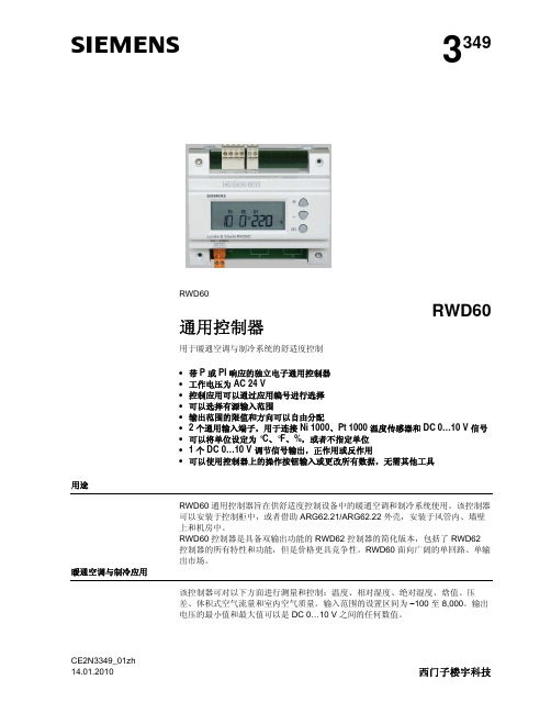
s3349RWD60RWD60通用控制器用于暖通空调与制冷系统的舒适度控制•带 P 或 PI 响应的独立电子通用控制器•工作电压为 AC 24 V•控制应用可以通过应用编号进行选择•可以选择有源输入范围•输出范围的限值和方向可以自由分配• 2 个通用输入端子,用于连接 Ni 1000、Pt 1000 温度传感器和 DC 0…10 V 信号•可以将单位设定为 °C、°F、%,或者不指定单位• 1 个 DC 0…10 V 调节信号输出,正作用或反作用•可以使用控制器上的操作按钮输入或更改所有数据,无需其他工具用途RWD60 通用控制器旨在供舒适度控制设备中的暖通空调和制冷系统使用。
该控制器可以安装于控制柜中,或者借助 ARG62.21/ARG62.22 外壳,安装于风管内、墙壁上和机房中。
RWD60 控制器是具备双输出功能的 RWD62 控制器的简化版本,包括了 RWD62控制器的所有特性和功能,但是价格更具竞争性。
RWD60 面向广阔的单回路、单输出市场。
暖通空调与制冷应用该控制器可对以下方面进行测量和控制:温度、相对湿度、绝对湿度、焓值、压差、体积式空气流量和室内空气质量。
输入范围的设置区间为−100 至 8,000。
输出电压的最小值和最大值可以是 DC 0…10 V 之间的任何数值。
CE2N3349_01zh2 / 10功能概览• 控制器独立的控制器,具备 1 个用于正作用或反作用的 DC 0…10 V 输出端子。
可调节参数,包括比例带和积分操作时间。
• 可选的辅助功能用于下列功能之一的通用输入端子 X2: − PI 限制器功能(绝对和相对) − 远程设定值功能 − 串级控制功能 − 设定值补偿− 冬季/夏季运行模式 − 最高优先级类型概览输入 输出 类型参考通用数字模拟数字2 0 1 0 RWD60名称 类型 用于墙面安装的小号保护外壳 ARG62.21 用于墙面安装的大号保护外壳 ARG62.22软件工具不适用设备组合以下西门子设备能够与 RWD60 通用控制器连接。
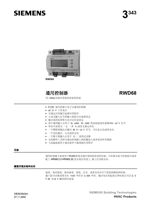
3343RWD68通用控制器RWD68用于HVAC及制冷系统的舒适性控制• P及PI 响应的独立电子式通用控制器• AC 24 V 工作电压• 可通过应用编号选择应用程序• 主动式输入信号的输入值段可以选择设定• 输出值的范围和方向可以任意设定• 两个通用输入点用于 Ni 1000, Pt 1000 的电阻温度传感器和0…10 V 信号• 单位可设置为 °C, °F, % 或者无指定单位• 一个模拟量输出点输出 DC 0…10 V 信号, 可以是正向或者反向• 一个双位输出, 正向或者反向• 一个数字量输入点用于 昼 / 夜设定切换• 无需额外工具即可通过控制器上的按键进入或者更改所有数据• 与电脑连接用于通过软件下载预制应用程序用途通用控制器主要适用于HVAC系统及制冷系统的舒适性控制。
可单独安装于控制盘中或者配上 ARG62.21/ARG62.22 盒安装在管道上, 墙上以及机房内.暖通空调及制冷应用温度, 相对湿度, 绝对湿度, 焓值, 压差, 流量及室内空气质量的测量和控制.输入值可以被设置为从 –100 单位至 8,000 单位. 输出电压的起始点和结束点可以是 0V DC 至10 V DC间的任意值.SIEMENS Building Technologies CE2N3343cn2/11功能概览• 控制器独立现场控制器,带有一个正向或者反向动作的 DC 0...10 V 输出信号和一个 2位 (开 / 关) 输出信号。
两位输出信号可以与模拟量输出信号相关或者不相关,模拟量信号可以是正向输出也可以是反向输出。
比例带和积分时间等参数可以调节。
• 可选辅助功能通用输入点 X2 用于下列功能之一: − PI 限制器功能 (绝对 & 相对) − 远程设定功能 − 串级控制功能− 设定点漂移(补偿)功能 − 冬/夏切换运行 − 最大优先权• 数字输入点 D1 用于昼/夜设定点转换输入点和输出点一览表输入输出类型通用点数字点模拟量数字点参考2 1 1 1RWD68名称类型用于墙上安装的小型保护外壳 ARG62.21 用于墙上安装的大型保护外壳 ARG62.22 软件工具S3341A031EN0组合设备下列西门子产品可与 RWD68通用控制器配合使用。
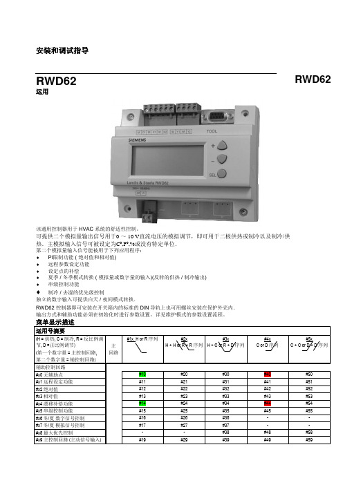
安装和调试指导RWD62运用该通用控制器用于 HVAC 系统的舒适性控制。
可提供二个模拟量输出信号用于0 ~ 10 V直流电压的模拟调节,即可用于二极供热或制冷以及制冷/供热.主模拟输入信号可被设定为C0,F0,%或没有特定单位.第二个模拟量输入信号能被用于下列应用程序:♦PI限制功能 ( 绝对值和相对值)♦远程参数设定功能♦设定点的补偿♦夏季 / 冬季模式转换 ( 模拟量或数字量的输入)(反转的供热 / 制冷输出)♦串级控制功能♦制冷 / 去湿的优先级控制独立的数字输入可提供白天 / 夜间模式转换.RWD62 控制器即可安装在开关箱内的标准的DIN导轨上也可用螺丝安装在保护外壳内.输出方式和辅助功能必须在初始化时进行参数设置,详见维护模式的参数设置流程。
菜单显示描述运用号摘要(H = 供热, C = 制冷, R = 反比例调节, D =正比例调节)(第一个数字量 = 主控制回路, 第二个数字量 = 辅控制回路)主回路#1x H or R序列#2xH + H or R + R 序列#3xH + C or R + D 序列#4xC or D序列#5xC + C orD + D 序列辅助控制回路#x0 无辅助点#10 #20 #30 #40 #50#x1 远程设定功能#11 #21 #31 #41 #51#x2 绝对值#12 #22 #32 #42 #52#x3相对值#13 #23 #33 #43 #53#x4 漂移补偿功能#14 #24 #34 #44 #54#x5 串级控制功能#15 #25 #35 #45 #55#x6冬/夏数字信号控制#16 #26 #36 - -#x7冬/夏模拟信号控制#17 #27 #37 - -#x8 最大优先控制- - #38 #48 #58#x9 主控制回路 (主动信号输入) #19 #29 #39 #49 #59RWD62Note: 运用的详细资料清单可向当地的供货商索取.如:RWD62的第30号运用号的资料代码为操作模式RWD 控制器有以下功能的操作按键: SELECT ✍ ✍ 选择键被用来进行确认和储存参数设置.通过上下按键进行参数的查看和调整. 操作超时在正常模式下调整设定参数时,如在20秒内无任何操作RWD 控制器将自动退出.但是,当处在参数设置的模式时, RWD 控制器将保持为PS 参数设置模式直至用户结束整个参数设置过程.注意仅在特定的程序或编程过程中出现相应的特定参数.如:假设第二个模拟输入未被使用,则X2的值和相应选项均不会出现.调试软件(S3341A031EN0)可进行运用号的选择和参数的调整 .该软件是基于WIN95及以上的操作平台,并可将设定的参数打印.可通过该软件对参数进行设置,从而使参数不在液晶屏上显示。
![西门子 温度控制器 RWD32[1].](https://img.taocdn.com/s1/m/59324ee90975f46527d3e1a8.png)
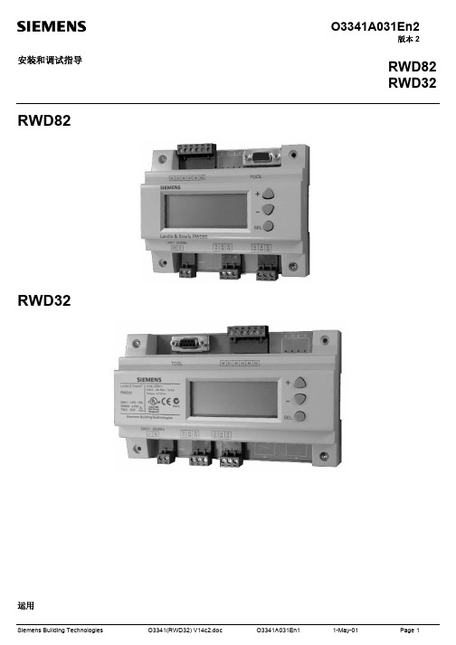
O3341A031En2版本 2安装和调试指导RWD82RWD32 运用RWD82RWD32该通用控制器用于 HVAC 系统的舒适性控制。
可提供二个数字量输出信号用于2级的开/关控制,或作为一个独立的三位控制器。
主模拟输入信号可被设定为C0,F0,%或没有特定单位.第二个模拟量输入信号能被用于下列应用程序:♦ PI限制功能 ( 绝对值和相对值)♦远程参数设定功能♦设定点的补偿♦夏季 / 冬季模式转换 ( 模拟量或数字量的输入)(反转的供热 / 制冷输出)♦串级控制功能♦制冷 / 去湿的优先级控制独立的数字输入可提供白天 / 夜间模式转换.RWD32/RWD82 控制器即可安装在开关箱内的标准的DIN导轨上也可用螺丝安装在保护外壳内.输出方式和辅助功能必须在初始化时进行参数设置,详见维护模式的参数设置流程。
注: 运用的详细资料清单可向当地的供货商索取.如:RWD32的第30号运用号的资料代码为RWD32/30.菜单显示描述1000Ω 温度传感器(不可更改)(仅对 0-10 Vdc 有效)X1Pt X1为兰吉尔.驷法公司的 Pt 1000Ω 温度传感器Pt 1000Ω: -20…180°C(不可更改)X2 LX2的起始点(仅对 0-10 Vdc 有效)-100…8000 X2Pt X2为兰吉尔.驷法公司的 Pt 1000Ω 温度传感器Pt 1000Ω: -20…180°C (不可更改) X1 HX1的终止点(仅对 0-10 Vdc 有效)-100…8000 X1 0-10 X1为 0-10 Vdc 输入信号传感器0-10 Vdc: -100 (8000)X2 H X2的终止点(仅对 0-10 Vdc 有效)-100…8000 X2 0-10X2为 0-10 Vdc 输入信号传感器 0-10 Vdc: -100 (8000)X2VR可变电阻 0…1000 ΩPS 1 – 运用号的选择:LIMABS绝对值LIM rEL相对值WIN/SUM diG 通过数字信号输入点进行 冬/夏季工况转换WIN/SUM AnLG 通过模拟信号输入点进行 冬/夏季工况转换 Act主动式的传感器(如:0~10VDC)的信号输入PS 3 辅助功能的参数设置在#8和#9运用号中无PS3的辅助参数功能.操作模式RWD 控制器有以下功能的操作按键: SELECT 选择键被用来进行确认和储存参数设置.通过上下按键进行参数的查看和调整. 操作超时在正常模式下调整设定参数时,如在20秒内无任何操作RWD 控制器将自动退出.但是,当处在参数设置的模式时, RWD 控制器将将保持为PS 参数设置模式直至用户结束整个参数设置过程.注意仅在特定的程序或编程过程中出现相应的特定参数.如:假设第二个模拟输入未被使用,则X2的值和相应选项均不会出现.调试软件(S3341A031EN0)可进行运用号的选择和参数的调整 .该软件是基于WIN95及以上的操作平台,并可将设定的参数打印.可通过该软件对参数进行设置,从而使参数不在液晶屏上显示。
CE2N3341en Siemens Building Technologies3341RWD32RWD82Universal ControllerRWD32RWD82For comfort control in HVAC & R-Systems • Standalone electronic temperature controller with P or PI response • Operating voltage in accordance to type AC 230 V or AC 24 V • Control application selectable via Application Number • Active input scale can be selectable• Two universal inputs for Ni 1000, Pt 1000 temperature sensors &0…10 V signals• Unit can be set as ºC, ºF, % or no specified unit• One 3-position output or two two-position outputs, direct or reverse action • One digital input for day/night changeover• Entering or changing of all data via operating buttons on the controller, possi-ble without additional tools•PC connection for downloading canned applications via the software toolUseThe universal controllers are intended for Heating, Ventilating, Air-Conditioning and Refrigeration in comfort control plants. It can be mounted in a control panel or in the ARG62.21/ARG62.22 housing on ducts, walls and in plant rooms.HVAC&R ApplicationMeasurement and control of temperature, relative humidity, absolute humidity, en-thalpy, pressure differential, volumetric airflow and indoor air quality. The input scalecan be set from –100 units to 8,000 units.Functions Summary• ControllerStand-alone controller with one 3-position or two 2-position (ON/OFF) outputs withindependent adjustment on each sequence for direct acting and/or reverse acting.In 3-position operation, the controller exhibits PI response.• Auxiliary selectable functionUniversal input X2 for one of the following functions:−PI limiter function (Absolute & Relative)−Remote setpoint function−Cascade control function−Setpoint compensation−Winter/summer operation−Maximum priority•Digital input D1 for setpoint changeover day/nightInput & Output summaryInputs Outputs(either)Operating TypeUniversal Digital3-position2-position voltage reference2112AC 230 V RWD322112AC24V RWD82 AccessoriesName TypeProtective small enclosure for wall mounting ARG62.21Protective big enclosure for wall mounting ARG62.22Software Tool S3341A031EN0 Equipment combinationsThe following Landis & Staefa units can be connected to RWD32 and RWD82 universalcontrollers.Units Data sheet no.Sensor with LG Ni 1000 temperature sensing element17... to 19...Sensor with Pt 1000 temperature sensing element1846Sensor with DC 0...10 V measuring signal17... to 19...1721 / 1748Room temperature sensor with setpoint adjuster QAA25or QAA25/APRemote setpoint adjusters FZA21.11 + FZA61.1119...Air damper actuators with 3-position input46...Valve actuators with 3-position input45...2/113/11Other combinations with third-party units are possible, provided the input and output specifications match the RWD32 and RWD82.A software tool for controller application selection and parameter adjustment is avail-able. It is a user-friendly Windows® 95 (or above) based software tool which provides you a printout of the controller settings.FunctionsThe RWD32 and RWD82 are stand-alone universal controllers, which perform both primary and auxiliary control functions. The respective mode is defined by entering the corresponding configuration and setting parameters via the push buttons on the con-troller or the software tool.The RWD32 and RWD82 controllers can be programmed as follows:• 2-position controller:Q1 and Q2reverse and/or direct acting on each step • 3-position controller:Q1 or Q2reverse or direct actingONONLoad2 Reverse Acting Sequences (Dependent loops)(Application No.: 10-19)2 Direct Acting Sequences (Dependent loops)(Application No.: 50-59)LoadLoad2 Reverse Acting Sequences(Independent loops)(Application No.: 20-29)2 Direct Acting Sequences (Independent loops)(Application No.: 60-69)Reverse and Direct Acting Sequences(Application No.: 40-49)Software ToolController typeMain functionsDependent Control LoopsIndependent Control LoopsReverse and Direct Acting Control Loops4/11LoadReverse Acting Sequence (Application No.: 30-39)Direct Acting Sequence (Application No.: 70-79)The universal input X1 is used as the primary input for a Landis & Staefa Ni 1000 tem-perature sensor, a Pt 1000 temperature sensor or a 0…10 V DC active input.The universal input X2 is used as the secondary input for a Landis & Staefa Ni 1000temperature sensor, a Pt 1000 temperature sensor, an active / passive remote setpoint transmitter or a 0…10 V DC active input.The digital input D1 is used to select the day/night changeover. Changeover occurs via potential-free contacts between D1 and M.Each output Q (Q1, Q2) can be configured for either reverse or direct acting.Ventilating plant with temperature controlX1Room temperature Q1Heating, reverse action Q2Cooling, direct actionOne of the following auxiliary functions can be selected:• PI limiter function (Absolute & Relative)• Remote setpoint function • Cascade control function • Setpoint compensation • Winter/summer operation • Maximum priorityAdditionally, the day and night operation mode is available.The limiter function with PI control enables abso-lute(or relative) maximum or minimum limitation of the supply air temperature (X2).When the value drops below or exceeds the limiter setpoint, the limiter function controls and takes prior-ity over the main setpoint.3341s 02A remote setpoint transmitter (FZA21.11, QAA25 or QAA25/AP), connected to X2 and configured ac-cordingly, enables setpoint adjustment.Active measurement from 0...10 V DC corresponding adjustable range from –100 to 8000Passive measurement from 0…1000 Ω correspond-ing adjustable range from –100 to 80003341s 033-point Control LoopUniversal input X1Universal input X2Digital input D1Digital outputs Q ExampleAuxiliary functions PI limiter functionRemote setpoint5/11X2 Supply air temperature sensorYou can select the PI/PI room/supply air tem-perature cascade control . In this case, the virtual PI room temperature controller determines thesetpoint within the limiter setpoints for the PI supply air temperature controller.Maximum Priority, coolingIf the value (0…10 V) of the input X2 is greater than the calculated output of the 3-point cooling sequence, the output will use the X2 input value as output value.The temperature setpoint X1 is shifted by the tem-perature as measured at sensor X2.Configuration of the RWD32 or RWD82 defines the influence on setpoint X1.The example shows the room air temperature set-point as controlled by the outside temperature.A digital switch or anlog input between terminals X2 and M can be used to implement win-ter/summer changeover.Digital changeoverWhen the contact is closed, summer operation is selected. Reverse acting output (Q1 only) is set to direct action (cooling).Analog changeoverWhen the X2 input exceeds the setpoint, summer operation is selected. Reverse acting output (Q1only) is set to direct action (cooling).A contact between terminals D1 and M can be used to implement setpoint changeover for day/night operation.When the contact is open, the setpoints for day operation are selected.When the contact is closed, the setpoints for night operation are selected.During the night mode, the following auxiliary func-tions are disabled: remote setpoint, abso-lute/Relative limiter, setpoint compensation andmaximum priority.Cascade control Maximum PrioritySetpoint compensationWinter/Summer operationDay/night setpoint6/11Mechanical design The RWD32 & the RWD82 universal controllers are as per DIN 43 880 Gr. 1 require-ments.A protective housing is used to protect the controller when mounted outside a control panel, such as on ducts, walls and in plant rooms. Furthermore, the protective housing prevents inadvertent contact with voltage supplying parts such as the connecting termi-nals.The RWD32 or RWD82 clips into the protective housing.The cable entries are located at the top and the bottom of the protective housing.The front has an opening for the LCD display and the programming buttons.The RWD32 and RWD82 universal controllers can be mounted as follows:• In a standard electrical control cabinet as per DIN 43 880• Wall mounted in a protective housing• Front mounting with standard available installation elementsPlug-in screw terminalsThe RWD32 and RWD82 are operated by the buttons on the controller front. Additional tools are not necessary. A 9-pin port is provided for optional programming via the soft-ware tool.RWD32RWD82The LCD shows the following information for normal operation:• Current operating values (maximum 4 digits)• Current setpoints (day/night)• Application number • Control sequencing diagram • Auxiliary input value• Selected auxiliary functionThe controller has three operating buttons for the following functions:The SELECT G button is used to enter or save the value adjustment.To configure the controller, follow the instructions supplied with the controller.HousingProtective housing ARG62.21/ARG62.22Mounting optionsTerminalsOperating and display elementsLCDOperating buttons SELECT GConfiguration7/11Engineering notes Use this controller only for applications as described in the description on the title page (bold print) and the section "Use". Additionally, observe all conditions and restrictions imposed in this section and in "Technical data".The sections marked with a warning symbol contain technical safety requirements and restrictions. Observe all of these warnings as they directly relate to the protection of person and equipment.Installation notesThe RWD32 and RWD82 controllers can be mounted as follows:Observe all local installation and mounting regulations.A On a DIN rail (EN 50 022-35 x 7.5) at least 120 mm long for RWD82 and 170 mm long for RWD32B Wall mounted with 2 screwsCFront mounted using standard elements.e.g. 1x DIN rail 150 mm long for RWD82 and 195 mm long for RWD32,2x hexagonal placeholders 50 mm, washers and screws DIn the ARG62.21/ARG62.22 protective housingA B C D3341z02Standard cables can be used for the controller. However, when mounting in an envi-ronment greatly exposed to EMI, use only shielded cables.• The RWD32 is designed for AC 230 V operating voltage.• The RWD82 is designed for AC 24 V operating voltage.The low voltage must comply with the requirements for safety extra-low voltage (SELV)as per EN 60730.Use safety insulating transformers with double insulation as per EN 60742; they must be designed for 100 % on-time.When using several transformers in one system, the connection terminals G0 must be galvanically connected.Supplying voltages above AC 24 V to low voltage connections may damage or destroy the controller or any other connected devices. Additionally, connections to voltages exceeding AC 42 V endanger personal safety.Intended useElectrical installation8/11Commissioning notesA booklet is supplied with the RWD32 & RWD82 controller for commissioning.Observe the following:• The controller must be configured for plant-specific operation using standard appli-cation number.• Plant specific fine tuning can be performed if required (refer to the commissioning booklet).• Power supply to the controller and the connected devices must be guaranteed • Values and settings entered remain available even on power failure.Technical data Operating voltage RWD32Operating voltage RWD82Safety extra-low voltage (SELV) as perFrequency RWD32Frequency RWD82AC 230 V ±15 %AC 24 V ±20 %EN 6073050 Hz/60 Hz 50 Hz/60 Hz RWD32RWD826.5 VA 3.5 VA Actual and nominal values 4 digitsL&S Ni 1000 ΩPt 1000 ΩActive sensor0.5 °C 0.5 °CDepends on the setting range TransportClimatic conditions Temperature HumidityMechanical conditions IEC721-3-2Class 2K3−25...+70 °C <95 % r.h.Class 2M2OperationClimatic conditions Temperature Humidity IEC721-3-3Class 3K50...+50 °C <95 % r.h.HousingFront and with ARG62.21Front and with ARG62.22IP 20 as per EN 60529IP 30 as per EN 60529IP 30 as per EN 60529Automatic electrical controls forhousehold and similar useEN 60730In accordance with European Union directivesElectromagnetic compatibility EMC Low voltage directive Emissions Immunity Safety89/336 EEC 73/23 EEC EN 50081-1EN 50082-1EN 60730N474Screw terminals for cables withmin. 0.5 mm dia.max. 2 x 1.5 mm 2 or 2.5 mm 2General data Po w er supplyPower consumption LCDDisplay resolution for (these values do not relate to the controller accuracy)Environmental conditionsEnvironmental conditionsIP codeProduct standards Other international approval Terminals9/11RWD82RWD320.297 kg 0.465 kgController Measuring RangeMax. cable length for dia. 0.6 mm −50…+150 °C max. 300 m Controller Measuring RangeMax. cable length for dia. 0.6 mm −20…+180 °C max. 300 mRangeMax. cable length for dia. 0.6 mm DC 0…10 V corresponding toadjustable range from –100 to 8000(°C, °F, % or no unit)max. 300 mRangeMax. cable length for dia. 0.6 mm0...1000 Ω corresponding to adjustable range from –100 to 8000 (°C, °F, % or no unit)max. 300 m Polling voltage for control commands (D…M)Current consumptionDC 15 V <15 mARelay contacts (potential-free)VoltageMaximum ratingMinimum ratingAC 24...230 VAC 230 V, 4 A resistive, 3 A ind. (per relay terminal)DC 30 V, 4 AAC 19.2 V, 20 mA DC 5 V, 100 mADiagramsD1Digital input G, G0L, N AC 230 V supplyM Ground (G0) for signal inputs and universal inputs Q...Digital output, various voltages permissible AC 24...230 V X1Signal input (main input: LS Ni 1000, Pt 1000 and 0…10 V DC)X2Signal input (aux. Input: LS Ni1000, Pt 1000, 0 …10 V DC and 0…1000 Ω or 0…10 V DC remote setpoint)ToolCommunication port for PC (9-pin plug)Weight without pack-agingAnalog inputs X1, X2L&S Ni 1000 Ω at 0 °C Pt 1000 Ω at 0 °C Analog voltages(for measured variables in °C, % or without unit)Remote setpoints X2Digital input D1Digital outputs Q1, Q2Internal diagram10/11E1Electrical load 2-position control N1RWD32/82 controllers PC Personal computerQ1/Q2Potential-free relay contacts for 3-position or 2-position control in 2 steps S1Time clock or switchX1Main input (Termination G appears when X1 is an active sensor)X2Auxiliary input or remote setpoint (Termination G appears when X2 is an active sensor)Y1Actuator with 3-position control AC 24...230 VPlease note that if you use a DESKTOP computer, the TOOL signal ground is galvani-cally connected to G0 inside the controller. If the signal line of the computer is grounded to Earth, the G0 line after TOOL connection will be Earthed as well.This will change from SELV to a PELV.Connection diagramNote11/11Siemens Building Technologies RWD32/RWD82 Universal controllerCE2N3341en Landis & Staefa Division17.07.2001Dimensions3341m 02RWD323341m 01RWD82150200ARG62.2161.2ARG62.21ã2001 Siemens Building Technologies Ltd.Subject to alteration。
RWD62U Technical Instructions Document No. 155-737January 14, 2005Universal ControllerDescription The Universal controller is intended for heating, air conditioning, ventilation andrefrigeration in comfort control applications. RWD62U main loop control applicationsare designed for temperature, static pressure, humidity, air pressure, fluid pressure,refrigeration, air quality and air fluid velocity control. The controller contains pre-programmed applications.Auxiliary control functions include:• Day/night setpoints• Remote setpoint control• Limiter control• Cascade control• Maximum priority• Setpoint compensation• Summer/winter operationControl parameters are adjusted for maximum comfort control via three buttons on theface of the device, or with a laptop computer and Siemens Building Technologiesprogram software.NOTE: For complete supporting technical documentation, including trainingpresentations, see /hvp/components.Features • Stand-alone electronic temperature controller with P or P+I response• 24 Vac operating voltage• Control application selectable via Application Number• Active input scale can be selectable• Limit and direction of the output scale can be freely assigned• Two universal inputs for Siemens 1000 ohm nickel (Ni 1000), 1000 ohm platinum(Pt 1000) temperature sensors and 0 Vdc to 10 Vdc signals• Unit can be set as °F, °C, % or no specified unit• Two modulating 0 to 10 Vdc signal outputs, direct or reverse action• One digital input for day/night changeover• Entering or changing of all data via operating buttons on the controller, possiblewithout additional tools• Computer connection for downloading canned applications via the software tool Product Number RWD62USiemens Building Technologies, Inc.Technical InstructionsRWD62U Universal ControllerDocument Number 155-737 January 14, 2005Warning/Caution NotationsCAUTION:Equipment damage may occur if you do not follow aprocedure as specified.SpecificationsPower SupplyOperating voltage 24 Vac + 20%Frequency 50/60 Hz Power consumption 2.5 VA LCDActual and nominal values Four digits Setpoint adjustment range -58°F to 302°F (-50°C to 150°C) Display Resolution(does not relate to controller accuracy)Siemens Ni 1000 ohm 1°F (0.5°C) Pt 1000 ohm 1°F (0.5°C) Active sensor Depends on setting range Environmental ConditionsStorage and transport Temperature -13°F to 158°F (-25°C to 70°C) Humidity <95% rh Operation Temperature 32°F to 122°F (0°C to 50°C) Humidity<95% rh UL UL listed to 916 Energy Management EquipmentTerminalsScrew terminals, min./max. conductors Minimum: 24 AWG (1) Maximum: 16 AWG (2), or 14 AWG (1)Weight RWD62U Controller 10.4 oz (295 grams)With packaging 12.24 oz (347 grams)Analog Inputs X1, X2 Siemens Ni 1000 ohm @ 32°F (0°C)Controller measuring range -58°F to 302°F (50°C to 150°C) Maximum cable length for 14 AWG Maximum 984 ft (300 m) Pt 1000 ohm at 32°F (0°C) Controller measuring range -4°F to 356°F (-20°C to 180°C)Maximum cable length for 14 AWG Maximum 984 ft (300 m)Analog voltages (For measured variable in °F, °C, % or without unit) Range 0 to 10 Vdc corresponding to adjustable range from –100 to 8000 (°C, °F, % or no unit)Maximum cable length for 14 AWG Maximum 984 ft (300 m)Remote setpoint X2 Range 0 to 1000 ohm corresponding toadjustable range from –100 to 8000 (°C, °F, % or no unit) Maximum cable length for 14 AWG Maximum 984 ft (300 m)Digital input D1 Polling voltage for control commands (D…M) 15 VdcCurrent consumption <15 mAAnalog outputs Y1, Y2 Range 0 to 10 VdcMaximum current +1 mA AccessoriesARG62.21 Protective enclosure for wall mounting. SEH62.1U Program ClockSEM62.2U 24/120 Vac Transformer125-3481 RWD Controller Programming Tool (CD) RWDTKU Tool KitPage 2 Siemens Building Technologies, Inc.RWD62U Universal Controller Technical InstructionsDocument Number 155-737January 14, 2005 Function Summary • ControllerStand-alone controller with two 0 to 10 Vdc outputs with independent adjustmenton each sequence for direct acting and/or reverse acting. Adjustable parameters,including proportional band and integral action time.• Auxiliary selectable function• Universal input X2 for one of the following auxiliary functions:− P+I limiter function (Absolute and Relative)− Remote setpoint− Cascade control− Setpoint compensation− Winter/summer operation− Maximum priority• Digital input D1 for setpoint changeover day/nightEquipment Combinations The following Siemens devices can be connected to RWD62U Universal Controllers. Other combinations with units from third-party manufacturers are possible, if the input and output specifications match the RWD62U.Table1.Description DocumentNumberSensor with Siemens Ni 1000 temperature sensing elementQAA25U Room temperature sensor with setpoint adjuster155-330GIB Series 310 lb-in Non Spring Return Actuators GBB Series 177 lb-in Non Spring Return Actuators 155-176P25 155-177P25GEB Series 132 in-lb Non Spring Return Actuators 155-318P25GCA Series 142 in-lb Spring Return Actuators 155-173P25155-174P25155-175P25GMA Series 62 in-lb Spring Return Actuators 155-315P25SKD Valve Actuator with proportional input 155-180P25SKB/SKC Valve Actuator with proportional input 155-163P25SQX Valve Actuator with proportional input 155-182P25SQS Valve Actuator with proportional input 155-190P25SSC Valve Actuator with proportional input 155-313P25SSB Valve Actuator with proportional input 155-192P25Electric Rack and Pinion proportional actuator 155-541P251/2 to 2-inch two-way globe valves 155-184P251/2 to 2-inch three-way globe valves 155-185P252-1/2 to 6-inch two-way flange valves 155-159P252-1/2 to 6-inch three-way flange valves 155-160P25MT Series 1/2 to 1-1/2-inch two-way globe valves 155-196P25MT Series 1/2 to 1-1/2-inch three-way globe valves 155-197P25MZ Series 1/2 to 1-inch two-way globe valves 155-198P25MZ Series 1/2 to I-inch three-way ball valves 155-199P25Differential Pressure Sensor 155-719 Siemens Building Technologies, Inc. Page 3Technical InstructionsRWD62U Universal ControllerDocument Number 155-737 January 14, 2005Software ToolAn optional, user-friendly, Windows® 95 (or later) based software tool for controller application selection and parameter adjustment is available. It provides you with a printout of the controller settings. This tool allows controller programming prior to installation.FunctionsController TypeThe RWD62U is a stand-alone universal controller, which performs both primary and auxiliary control functions. The respective mode is defined by entering thecorresponding configuration and setting parameters via the push buttons on the controller or the software tool.Main FunctionsThe RWD62U controller can be programmed as follows: • One sequence: Y1 or Y2 Reverse or direct acting • Two sequences: Y1 and Y2 Reverse and direct acting or Y1 and Y2 Reverse and reverse acting orY1 and Y2Direct and direct actingNOTE: Direct Acting – As air temperature increases, the control output increases.Reverse Acting – As air temperature increases, the control output decreases.T H 0599R 3= TEMPERATURE SENSOR = AIR DAMPER ACTUATOR = HEATING COIL = COOLING COIL= HEATING OR COOLING COIL (TWO-PIPE)= FAN OR PUMP = TIME CLOCK= REMOTE SET POINT UNIT = OUTSIDE AIR SENSOR++--Figure 1. Frequently Used Symbols in Application Drawings.T H 0786R1O u t p u t V o l t a g eTemp.Figure 2. One Sequence Heat, DirectActing or Reverse Acting (Application 10 to 19).O u t p u t V o l t a g eTemp.T H 0787R 1Figure 3. Two Sequence Heat, Two Direct Acting or Two Reverse Acting Sequences(Application 20 to 29).O u t p u t V o l t a g eT H 0788R 1Figure 4. One Direct Acting Heat and One Direct Acting Cool or One Reverse ActingHeat and One Direct Acting CoolSequence(Application 30 to 39).T H 0789R 1Temp.O u t p u t V o l t a g eFigure 5. One Direct Acting Cool or OneReverse Acting Cool Sequence(Application 40 to 49).Page 4Siemens Building Technologies, Inc.RWD62U Universal Controller Technical Instructions Document Number 155-737January 14, 2005O u t p u t V o l t a g eTemp.T H 0790R 1Figure 6. Two Direct Acting Cool or Two Reverse Acting Cool Sequences(Application 50 to 59).Universal Input X1 The primary input for a Siemens Ni 1000 temperature sensor, a Pt 1000 temperaturesensor, or a 0 to 10 Vdc active input.Universal Input X2The secondary input for a Siemens Ni 1000 temperature sensor, a Pt 1000temperature sensor, an active/passive remote setpoint transmitter, or a 0 to 10 Vdc active input.Digital Input D1 Selects the day/night changeover. Changeover occurs via potential-free dry contacts between D1 and M. Typically, a time clock controls D1 input.Analog Outputs Each output (Y1, Y2) can be configured for either reverse or direct acting. Themodulating voltage output (Y…) controls the devices requiring a 0 to 10 Vdc signal.ExampleT H 0791R 1Figure 7. Constant Volume with TemperatureControl, Direct Acting/Reverse Acting.X1 Room temperature Y1 Heating, direct action Y2 Cooling, reverse actionT H 0811R 1Figure 8. Constant Volume with TemperatureControl, Reverse Acting/Direct Acting.X1 Room temperature Y1 Heating, reverse action Y2 Cooling, direct actionAuxiliary FunctionsOne of the following auxiliary functions can be selected: • P+I limiter (Absolute, #x2 and Relative, #x3) • Remote setpoint, #x1 • Cascade control, #x5 • Setpoint compensation, #x4• Winter/summer operation, Digital #x6, Analog #x7 • Maximum priority, #x8• Main loop 0 to 10V input, #x9Day and night operation mode is also available.Siemens Building Technologies, Inc. Page 5Technical InstructionsRWD62U Universal ControllerDocument Number 155-737 January 14, 2005P+I Limiter Function NOTE: In the followingillustrations, the heating and cooling outputs are D.A. Outputs can be reversed.T H 0794R 1Figure 9. P+I Limiter Function.The limiter function with P+I control enables absolute (or relative) maximum or minimum limitation of the supply air temperature (X2).When the value drops below or exceeds the limiter setpoint, the limiter function controls and takes priority over the main setpoint.Remote SetpointNOTE: You cannot selectthe remote setpoint auxiliary function in Night mode.T H 0793R 1Figure 10. Remote Setpoint.A remote setpoint transmitter (QAA25U), connected to X2 and configured accordingly, enables setpoint adjustment.Active measurement from 0 to 10 Vdc corresponding adjustable range from –100 to 8000 unitsPassive measurement from 0 to 1000 Ω corresponding adjustable range from –100 to 8000 units Cascade ControlT H 0794R 1Figure 11. X2 Supply Air TemperatureSensor.You can select the P+I/P+I room/supply air temperature cascade control. In this case, the virtual P+I room temperature controller determines the setpoint within the limiter setpoints for the P+I supply air temperature controller.Maximum PriorityNOTE: You cannot selectthe maximum priority auxiliary function in Night mode.T H 0795R 1Figure 12. Maximum Priority,Cooling.If the value (0 to 10V) of the input X2 is greater than the calculated output of the cooling sequence, the output will use the X2 input value as output value. This is active even when the controller is working with the heating sequence. Setpoint CompensationT H 0796R 1Figure 13. Setpoint Compensation.The temperature setpoint X1 is shifted by the temperature as measured at sensor X2.Configuration of the RWD62U defines the influence on setpoint X1. The example shows the room airtemperature setpoint as shifted by the outside temperature.Page 6Siemens Building Technologies, Inc.RWD62U Universal Controller Technical Instructions Document Number 155-737January 14, 2005Winter/Summer OperationT H 079Summer Setpoint Winter SetpointFigure 14. Winter/Summer Operation.A digital switch or analog input between terminals X2 and M will implement winter/summer changeover.When adjusting setpoints, the heating setpoint must be less than the cooling setpoint.Digital changeoverWhen the contact is closed, summer operation is selected. Reverse actingoutput (Y1 only) is set to direct action (cooling).Analog changeoverSummer operation is selected when the X2 input exceeds the setpoint Reverse acting output (Y1 only) is set to direct action (cooling).Day/Night SetpointT H 0798R 1Figure 15. Day/Night Setpoint.A contact between terminals D1 and M can be used to implement setpoint changeover for day/night operation.When the contact is open, the setpoints for day operation are selected.When the contact is closed, the setpoints for night operation are selected. During the night mode, the following auxiliary functions are disabled: remote setpoint, absolute/relative limiter, setpoint compensation and maximum priority.Mechanical DesignProtective Housing ARG62.21 • This UL-approved plastic housing protects the controller when mounted outside a control panel, such as on ducts, walls and in mechanical rooms. This housing also prevents inadvertent contact with voltage supplying parts such as the connecting terminals. • The RWD62U clips into the housing.• The cable entries are located at the top and the bottom of the ARG62.21 housing. • The front has an opening for the LCD display and the programming buttons.TerminalsPlug-in screw terminalsSiemens Building Technologies, Inc.Page 7Technical Instructions RWD62U Universal Controller Document Number 155-737January 14, 2005Operating and Display Elements The RWD62U is operated by the buttons on the controller front.Additional tools are not necessary. The controller can also be programmed via the software tool, which plugs into the nine-pin port.Function ButtonsFigure 16. RWD62U Universal Controller.LCDThe LCD shows the following information for normal operation:• Current operating values (maximum four digits)• Current setpoints (day/night)• Application number• Control sequencing diagram• Auxiliary input value• Selected auxiliary functionOperating ButtonsThe controller has three operating buttons for the following functions:The SELECT ● button is used to enter or save the value adjustment. Configuration To configure the controller, follow the instructions supplied with the controller.Page 8 Siemens Building Technologies, Inc.RWD62U Universal Controller Technical Instructions Document Number 155-737January 14, 2005Installation NotesThe RWD62U controller can be mounted as follows:NOTE: Observe all local installation regulations and building codes. A On a DIN rail at least 4.7 inches (120 mm) long B Wall-mounted with two #6 screws CFront-mounted using standard hardware: • One DIN rail 5.9 inches (150 mm) long • Two hexagonal blocks 1.97 inches (50 mm) • Washers and screws DIn the ARG62.21 protective housingT H 0741R 1A B C DFigure 17. Mounting Options.Electrical Installation NotesCAUTION:• Standard cables can be used for the controller. However, when mounting in an environment greatly exposed to Electrical Magnetic Interface (EMI), use only shielded cables. • The RWD62U is designed for 24 Vac operating voltage. • Use safety insulating transformers with double insulation; they must be designed for 100% duty. • When using several transformers in one system, the connection terminals G0 (ground) must be galvanically connected. • Supplying voltages above 24 Vac to low voltage connections may damage or destroy the controller or any other connected devices. • Connections to voltages exceeding 24 Vac endanger personal safety. • The ARG62.21 Protective Housing does not provide grounding between conduit connections. Use grounding bushings and jumper wires or equivalent.Commissioning NotesA commissioning booklet is included with the RWD62U controller. Observe the following:• The controller must be configured for application-specific operation using the standard application number. • Application-specific fine tuning can be performed if required (see the commissioning booklet ).• Power supply to the controller and the connected devices must be guaranteed. • Values and settings entered remain available even on power failure.Siemens Building Technologies, Inc.Page 9Technical InstructionsRWD62U Universal ControllerDocument Number 155-737 January 14, 2005Wiring DiagramsT H 0800R 1D1 Digital input G, G0 24 Vac supply M Ground (G0) for signal inputs and universal inputs and analog outputs X1 Signal input (main input: Siemens Ni 1000, Pt 1000 and 0 to10 Vdc) X2 Signal input (aux. Input: Siemens Ni1000, Pt 1000, 0 to10 Vdc and 0 to 1000 Ω or 0 to 10 Vdc remote setpoint) Y1, Y2 Analog outputs Tool Communication port for PC (9-pin plug)Figure 18. RWD62U Wiring Diagram.T H 0801R 1N1 RWD62U controller PC Personal computer S1 Time clock or switch SN System neutral SP System potential X1 Main input (Termination G appears when X1 is an active sensor) X2 Auxiliary input or remote setpoint (Termination G appears when X2 is an active sensor)Y1, Y2 Valve actuator 1 and 2/Damper actuator 1 and 2Figure 19. Connection Diagram.CAUTION: if you use a DESKTOP computer, the TOOL signal ground isgalvanically connected to G0 inside the controller. If the signal line of the computer is grounded to Earth, the G0 line after TOOL connection will be grounded as well.Page 10 Siemens Building Technologies, Inc.RWD62U Universal Controller Technical Instructions Document Number 155-737January 14, 2005Information in this publication is based on current specifications. The company reserves the right to make changes in specifications and models as design improvements are introduced. Other product or company names mentioned herein may be the trademarks of their respective owners. © 2005 Siemens Building Technologies, Inc. Siemens Building Technologies, Inc. 1000 Deerfield ParkwayYour feedback is important to us. If you have comments about this document, please sendDimensionsIn Inches (Millimeters)T H 0802R 1Figure 20. RWD62U Controller Dimensions.T H 0745R 15.91 (150)7.87 (200)2.41 (61.2)Figure 21. ARG62.21 Enclosure Dimensions.Buffalo Grove, IL 60089-4513 U.S.A.them to ****************************Page 11Document No. 155-737 Country of Origin: US。
安装和调试指导RWD62 RWD62Siemens Building Technologies 1830757275.doc.doc O3342A031En1 1-May-01 Page 1运用该通用控制器用于 HVAC 系统的舒适性控制。
可提供二个模拟量输出信号用于0 ~ 10 V直流电压的模拟调节,即可用于二极供热或制冷以及制冷/供热.主模拟输入信号可被设定为C0,F0,%或没有特定单位.第二个模拟量输入信号能被用于下列应用程序:♦PI限制功能 ( 绝对值和相对值)♦远程参数设定功能♦设定点的补偿♦夏季 / 冬季模式转换 ( 模拟量或数字量的输入)(反转的供热 / 制冷输出)♦串级控制功能♦制冷 / 去湿的优先级控制独立的数字输入可提供白天 / 夜间模式转换.RWD62 控制器即可安装在开关箱内的标准的DIN导轨上也可用螺丝安装在保护外壳内.输出方式和辅助功能必须在初始化时进行参数设置,详见维护模式的参数设置流程。
Note: 运用的详细资料清单可向当地的供货商索取.如:RWD62的第30号运用号的资料代码为RWD62/30.Page 2 1-May-01 1830757275.doc.doc O3342A031En1 Siemens Building Technologies..;,.PS 3 辅助功能的参数设置:在#8和#9运用号中无PS3的辅助参数功能.Page 4 1-May-01 1830757275.doc.doc O3342A031En1 Siemens Building Technologies..;,.操作模式RWD 控制器有以下功能的操作按键:SELECT ● ● 选择键被用来进行确认和储存参数设置.通过上下按键进行参数的查看和调整.操作超时在正常模式下调整设定参数时,如在20秒内无任何操作RWD 控制器将自动退出.但是,当处在参数设置的模式时, RWD 控制器将保持为PS 参数设置模式直至用户结束整个参数设置过程.注意仅在特定的程序或编程过程中出现相应的特定参数.如:假设第二个模拟输入未被使用,则X2的值和相应选项均不会出现.调试软件(S3341A031EN0)可进行运用号的选择和参数的调整 .该软件是基于WIN95及以上的操作平台,并可将设定的参数打印.可通过该软件对参数进行设置,从而使参数不在液晶屏上显示。
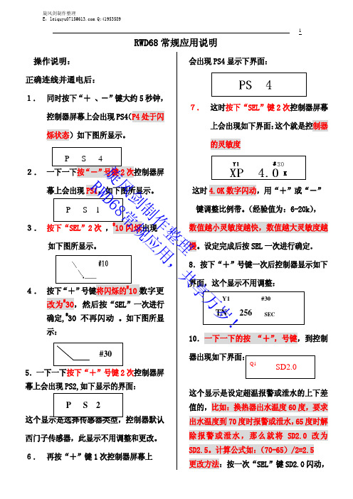
RWD68RWD62RWD60调试说明RWD系列控制箱调试指导说明调度步骤:●同时按“+/-”键持续约5秒,至PS4菜单(系统参数菜单)●按“-”键至PS3菜单(室外补偿菜单),若在PS1中没有选择室外温度补偿功能,则此菜单缺省。
●按“-”键至PS2菜单(传感器定义菜单),若无PS3菜单则直接至PS2菜单●按“-”键至PS1菜单(功能号选择菜单)●按“SEL”键(选择)进入PS1菜单●按“SEL”键(选择),#闪烁,通过“+/-”键,进行功能号选择:#10常规供热使用,模拟量反比例调节,继电器正向输出;:#14常规供热使用,带室外温度补偿功能,模拟量反比例调节,继电器正向输出。
★此曲线为常规控制换热器的电动阀所用,在调度前请先校核曲线号是否正确●先调***所需要的功能号后,按按“SEL”键(确认)●按“+”键,出现“NEXT PS”(进入下一级菜单提示)●再按“+”键,回至PS2菜单(传感器定义菜单)●按“SEL”键(选择)进入PS2菜单中子菜单※ 物理量单位选择“UNT ℃”(默认值:℃ )物理量℃ (摄氏度,温度控制常用)物理量OF (华氏度,温度控制常用)物理量--- (无单位,压力控制常用)物理量% (百分比,湿度控制常用)通过“-”键选择后,按“SEL”键后,再按“+”键,进入子菜单※ 传感器类型选择:X1 LS,SIEMENS Ni 1000传感器 PT( pt1000)0-10(0-10V直流电压信号)通过“+/-”键,选择传感器类型,按“SEL”键确认,按“+”键进入子菜单※ 传感器偏差,“X1——K”(默认值为0)若传感器测量温度有误差,可通过些菜单“+/-”键设定相应正/负值进入低高偏差修正,并按按“SEL”键确认后,按“+”键进入子菜单※ 传感器测量范围:X1L:(X1传感器测量下限);X1H:(X1传感器测量上限)★ 说明:若采用带温度补偿功能,则继续确认X2传感器的测量范围。
安装和调试指导
RWD62
运用
该通用控制器用于 HVAC 系统的舒适性控制。
可提供二个模拟量输出信号用于0 ~ 10 V 直流电压的模拟调节,即可用于二极供热或制冷以及制冷/供热.主模拟输入信号可
被设定为C 0,F 0
,%或没有特定单位.
第二个模拟量输入信号能被用于下列应用程序: ♦ PI 限制功能 ( 绝对值和相对值) ♦ 远程参数设定功能 ♦ 设定点的补偿
♦ 夏季 / 冬季模式转换 ( 模拟量或数字量的输入)(反转的供热 / 制冷输出) ♦ 串级控制功能
♦
制冷 / 去湿的优先级控制
独立的数字输入可提供白天 / 夜间模式转换.
RWD62 控制器即可安装在开关箱内的标准的DIN 导轨上也可用螺丝安装在保护外壳内. 输出方式和辅助功能必须在初始化时进行参数设置,详见维护模式的参数设置流程。
菜单显示描述
运用号摘要
(H = 供热, C = 制冷, R = 反比例调节, D =正比例调节)
(第一个数字量 = 主控制回路, 第二个数字量 = 辅控制回路) 主 回路
#1x H or R 序列
#2x H + H or R + R 序列 #3x
H + C or R + D 序列
#4x C or D 序列
#5x
C + C or
D + D 序列
辅助控制回路
#x0 无辅助点
#10 #20 #30 #40 #50 #x1 远程设定功能
#11 #21 #31 #41 #51 #x2 绝对值
#12 #22 #32 #42 #52 #x3相对值
#13 #23 #33 #43 #53 #x4 漂移补偿功能
#14 #24 #34 #44 #54 #x5 串级控制功能
#15 #25 #35 #45 #55 #x6冬/夏 数字信号控制
#16 #26 #36 - - #x7冬/夏 模拟信号控制
#17 #27 #37 - - #x8 最大优先控制
- - #38 #48 #58 #x9 主控制回路 (主动信号输入) #19 #29 #39 #49 #59 Note: 运用的详细资料清单可向当地的供货商索取.如:RWD62的第30号运用号的资料代码为RWD62/30. 名字 描述 显示及设定范围 名字
描述 显示及设定范围 一般屏幕显示
可调整的设定值界面
Y1 模拟量输出1 0.0…10.0 Vdc #10
运用号
10…59 (不连续的号
Y2
模拟量输出2
0.0…10.0 Vdc
RWD62
+
-
操作模式
RWD 控制器有以下功能的操作按键: SELECT ✍ ✍ 选择键被用来进行确认和储存参数设置.
通过上下按键进行参数的查看和调整.
操作超时 在正常模式下调整设定参数时,如在20秒内无任何操作RWD 控制器将自动退出.但是,当处在参数设置的模式时, RWD 控制器将保持为PS
参数设置模式直至用户结束整个参数设置过程.
注意
仅在特定的程序或编程过程中出现相应的特定参数.如:假设第二个模拟输入未被使用,则X2的值和相应选项均不会出现.
调试软件(S3341A031EN0)可进行运用号的选择和参数的调整 .该软件是基于WIN95及以上的操作平台,并可将设定的参数打
印.可通过该软件对参数进行设置,从而使参数不在液晶屏上显示。
主显示菜单:
主显示为:
(a) Y1 & Y2 模拟输出信号为直流电压信号. (0 …10V 在液晶显示屏上的显示为 0, 1, 2…10)
同时按上下箭头5秒钟即可进入PS 参数设置模式.
:按向上的箭头进入后一级菜单界面或增加参数的值.
:按向下的箭头进入前一级菜单界面或增加参数的值. :当显
✍ ✍
✍
✍
接线图
RWD62
N1 RWD62 控制器
X1 主温度传感器 (当X1接的传感器为主动式传感器时,端子
G被使用)
X2 辅温度传感器 (当X2接的传感器为主动式传感器时,端子
G被使用)
S1 计时器或开关
Y1, Y2 水阀驱动器 1 & 2 / 风阀驱动器 1 & 2
PC 台式计算机或便携式计算机
: 继电器触点的交流电压为交流24~230V.
请注意计算机的TOOL通讯端口的信号地和RWD62控制器的
G0是内部连通的.注意接地和共地的问题.
内部接线图 / 接线端子图
和远程设
RWD62
安装方式
四种安装
安装
RWD62
A 安装在
B 用2 个螺丝安装在墙上
螺丝的长度至少为40mm(螺丝口径为?3.2mm.)
C 前门面板安装
e.g. 1x DIN导轨,长度为150 mm,
2 个六角型的长度为50mm螺纹的螺栓, 垫片和螺丝.
(在最后安装前面板之前请确保所有的接线端子已接线无误)
D安装在 ARG62.21/ARG62.22内 .
注解:所有接线端子和外壳之间至少需要 8mm 空间以保证人身安全.
当控制器所在的环境中有EMC.
•The RWD62的工作电源为交流
工作电压必须满足EN 60 730的安全超低电压(SELV)的需求。
使用符合EN60 742的双绝缘安全变压器。
它们必须能满足100%连续负载要求。
如果您的系统中使用了几个变压器,所有变压器的G0终端必须可靠接地。
如将超过交流24V的电压和低电压连接将损害控制器或连接设备。
另外,超过42V的电压将对人身安全造成伤害。
ARG62.21外壳安装尺寸。