8路干接点输入,继电器输出,开关量
- 格式:doc
- 大小:379.50 KB
- 文档页数:4
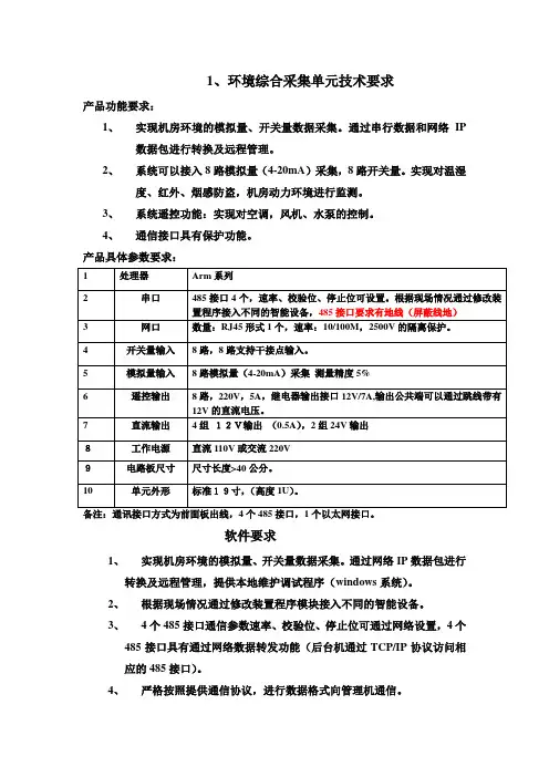
1、环境综合采集单元技术要求
产品功能要求:
1、实现机房环境的模拟量、开关量数据采集。
通过串行数据和网络IP
数据包进行转换及远程管理。
2、系统可以接入8路模拟量(4-20mA)采集,8路开关量。
实现对温湿
度、红外、烟感防盗,机房动力环境进行监测。
3、系统遥控功能:实现对空调,风机、水泵的控制。
4、通信接口具有保护功能。
产品具体参数要求:
备注:通讯接口方式为前面板出线,4个485接口,1个以太网接口。
软件要求
1、实现机房环境的模拟量、开关量数据采集。
通过网络IP数据包进行
转换及远程管理,提供本地维护调试程序(windows系统)。
2、根据现场情况通过修改装置程序模块接入不同的智能设备。
3、4个485接口通信参数速率、校验位、停止位可通过网络设置,4个
485接口具有通过网络数据转发功能(后台机通过TCP/IP协议访问相
应的485接口)。
4、严格按照提供通信协议,进行数据格式向管理机通信。
环境综合采集单元1U单元机壳后视图。
测速和超速保护卡(SDP)及其端子板使用说明(有6路模拟量输入)编制:⎽⎽⎽⎽⎽⎽⎽⎽⎽⎽⎽⎽⎽⎽⎽⎽⎽⎽⎽⎽校对:⎽⎽⎽⎽⎽⎽⎽⎽⎽⎽⎽⎽⎽⎽⎽⎽⎽⎽⎽⎽审核:⎽⎽⎽⎽⎽⎽⎽⎽⎽⎽⎽⎽⎽⎽⎽⎽⎽⎽⎽⎽审定:⎽⎽⎽⎽⎽⎽⎽⎽⎽⎽⎽⎽⎽⎽⎽⎽⎽⎽⎽⎽批准:⎽⎽⎽⎽⎽⎽⎽⎽⎽⎽⎽⎽⎽⎽⎽⎽⎽⎽⎽⎽新华控制工程有限公司二00四年四月转速测量和超速保护卡及端子板使用说明1. 概述SDP卡是转速量测速和超速保护功能合二为一的DEH/MEH专用卡件。
在DEH系统中为保证冗余设计,采用3块SDP卡分布在3个不同的站,3块SDP卡与SDP端子板( CCC2.908.402)配合使用,构成硬件三选二超速保护系统。
在DEH/MEH系统中,SDP板作为一个前端数据处理器,将转速信号转换成相应的数字信号,经I/O总线送至控制计算机系统中,用于转速控制等。
同时SDP卡对转速进行逻辑,并发出超速保护信号,控制超速限制(OPC)电磁阀或停机电磁阀,防止汽轮机超速。
SDP卡在DEH系统中还可以根据输入电负荷和汽负荷的瞬间不平衡,产生超速保护的信号。
DEH/MEH系统的超速保护功能由SDP及其端子板完成,与DPU独立。
同时SDP卡上的所有信息都可以通过DPU读取在操作员站及工程师站的画面上显示。
2. 硬件组成测速及超速保护硬件系统由SDP卡及端子板组成,一般在设计时都采用三块SDP卡和一块SDP端子板组成硬件的三选二系统。
2.1 SDP测速卡2.1.1 简介SDP为汽机控制系统中专用的测速及超速保护模件,模件上采用AMD 188EM为16位嵌入式CPU,它具有与速度快、数据处理能力强PC机的指令相兼容。
因此,具有较强的软件开发手段。
最大寻址空间为存贮器1Mbyte,I/O为64K,有3个16位定时器/计数器、多级中断、8个优先级等功能。
程序存储器FLASH ROM(AMD 29F040),FLASH ROM中固化了32K的EMON86 V3.21和PI的执行程序,数据存储器一片628128 128K字节的RAM,该RAM主要用于程序的运行和数据计算。
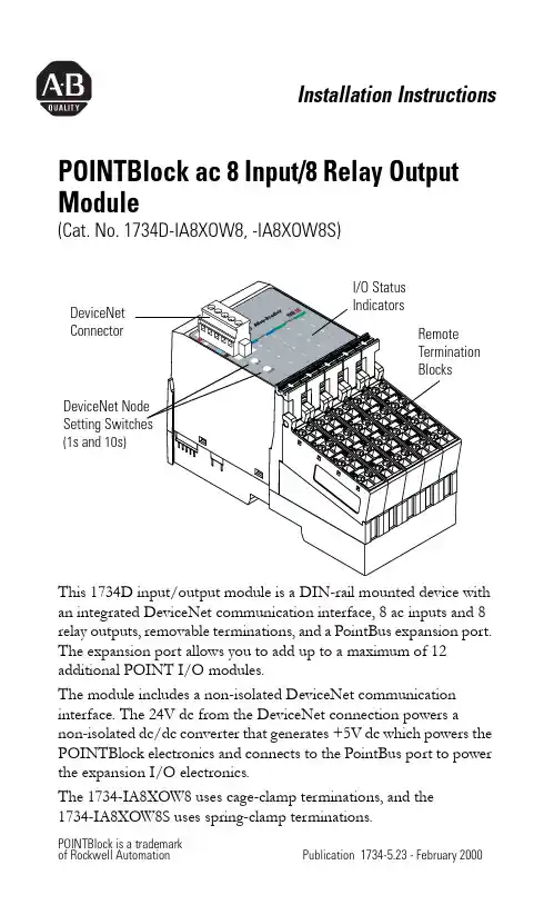
Installation Instructions POINTBlock ac 8 Input/8 Relay Output Module(Cat. No. 1734D-IA8XOW8, -IA8XOW8S) ArrayThis 1734D input/output module is a DIN-rail mounted device with an integrated DeviceNet communication interface, 8 ac inputs and 8 relay outputs, removable terminations, and a PointBus expansion port. The expansion port allows you to add up to a maximum of 12 additional POINT I/O modules.The module includes a non-isolated DeviceNet communication interface. The 24V dc from the DeviceNet connection powers a non-isolated dc/dc converter that generates +5V dc which powers the POINTBlock electronics and connects to the PointBus port to power the expansion I/O electronics.The 1734-IA8XOW8 uses cage-clamp terminations, and the1734-IA8XOW8S uses spring-clamp terminations.2 POINTBlock ac 8 Input/8 Relay Output ModuleWhatever field power you supply is connected to the internal field-power bus. For example, if 120V ac is applied to the power connections, there will be 120V ac applied to the modules through the internal field-power bus.POINT I/O modules to the right of the module will also have that internal power bus voltage applied, unless you use a 1734-FPD to interrupt and change the field power-bus voltage.ConnectorPointBus Expansion Port (allows expansion of up to 12 POINT I/O modules)I/O ConnectionsPower Connections 41971120V acPOINTBlock ac 8 Input/8 Relay Output Module 3To set the node address, set the combination of 1’s and 10’s tocorrespond to the required address. (For example, for 61, set the 10’s switch to 6 and the 1’s switch to 1.)POINTBlock is designed to be grounded through the DIN rail to chassis ground. To assure proper grounding of POINTBlock and POINT I/O adapters and terminal bases to chassis ground, the recommended DIN rail material is zinc-plated, yellow-chromated steel. Mount POINTBlock, POINT I/O adapters and terminal bases only to zinc-plated, yellow-chromated steel.4200410’s Node Address Rotary Switch4 POINTBlock ac 8 Input/8 Relay Output ModuleWiring120V acRTB 0RTB 1RTB 2RTB 3RTB 4This supply will be connected to the internal power bus. NC = No connectionL2/N = AC Return/Neutral L1 = AC Power41976POINTBlock ac 8 Input/8 Relay Output Module 5Input WiringNote: When connecting more than 1 wire in a termination point, make sure that both wires are the same gauge and type.ChannelInput TerminalReturnVoltageRemote Termination Block 10046115722463357Remote Termination Block 24046515762467357120V ac is supplied through the internal power bus.41967acL1 = 120V ac L2 = Return6 POINTBlock ac 8 Input/8 Relay Output ModuleOutput WiringChannel Output Common SupplyRemote Termination Block 30A 00B 21A 11B 32A 42B 63A 53B 7Remote Termination Block 44A 04B 25A 15B 36A 46B 67A 57B7Supply voltage is 120V ac.12/24V dc power for the module is provided by the internal power bus.L1 = 120V ac L2 = ReturnPOINTBlock ac 8 Input/8 Relay Output Module 7N ote: When connecting more than 1 wire in a termination point,make sure that both wires are the same gauge and type.DeviceNet Connector WiringDeviceNet connection-V42132+V CAN - High Shield CAN - Low8 POINTBlock ac 8 Input/8 Relay Output ModuleThe following information applies when operating this equipment in hazardous locations:Informations sur l’utilisation de cet équipement en environnements dangereux :Products marked “CL I, DIV 2, GP A, B, C, D” are suitable for use in Class I Division 2 Groups A, B, C, D, Hazardous Locations and nonhazardous locations only. Each product is supplied with markings on the rating nameplate indicating the hazardous location temperature code. When combining products within a system, the most adverse temperature code (lowest “T” number) may be used to help determine the overall temperature code of the system. Combinations of equipment in your system are subject to investigation by the local Authority Having Jurisdiction at the time of installation.Les produits marqués "CL I, DIV 2, GP A, B, C, D" ne conviennent qu’à une utilisation en environnements de Classe I Division 2 Groupes A, B, C, D dangereux et non dangereux. Chaque produit est livré avec des marquages sur sa plaque d’identification qui indiquent le code de température pour les environnements dangereux. Lorsque plusieurs produits sont combinés dans un système, le code de température le plus défavorable (code detempérature le plus faible) peut être utilisé pourdéterminer le code de température global dusystème. Les combinaisons d’équipements dans le système sont sujettes à inspection par les autorités locales qualifiées au moment de l’installation.EXPLOSION HAZARD •Do not disconnectequipment unlesspower has beenremoved or the areais known to benonhazardous. •Do not disconnectconnections to thisequipment unlesspower has beenremoved or the areais known to benonhazardous.Secure any externalconnections thatmate to thisequipment by usingscrews, slidinglatches, threadedconnectors, or othermeans providedwith this product.•Substitution ofcomponents mayimpair suitability forClass I, Division 2.•If this productcontains batteries,they must only bechanged in an areaknown to benonhazardous.RISQUE D’EXPLOSION •Couper le courant ou s’assurer quel’environnement estclassé non dangereuxavant de débrancherl'équipement.•Couper le courant ou s'assurer quel’environnement estclassé non dangereuxavant de débrancherles connecteurs. Fixertous les connecteursexternes reliés à cetéquipement à l'aidede vis, loquetscoulissants,connecteurs filetés ouautres moyens fournisavec ce produit.•La substitution decomposants peutrendre cetéquipement inadaptéà une utilisation enenvironnement deClasse I, Division 2.•S’assurer quel’environnement estclassé non dangereuxavant de changer lespiles.POINTBlock ac 8 Input/8 Relay Output Module 9Specifications - 1734D-IA8XOW8, -IA8XOW8SInput SpecificationsON-State Voltage65V ac minON-State Current 5.0mA minOFF-State Voltage43V ac maxOFF-State Current 2.5mA maxNominal Input Impedance17.0kΩInput Delay Time OFF to ONON to OFF 20ms hardware + (0-65ms selectable) 20ms hardware + (0-65ms selectable)External AC Power SupplyVoltage120V ac, 60Hz nominalExternal AC Power SupplyVoltage Range85-132V ac, 47-63HzOutput SpecificationsRelay Type Form A, normally open (N.O.)Single Pole, Single Throw (SPST)Output Voltage Range (load dependent)********************* ******************* ********************* ******************** ********************Output Current Rating (at rated power)Resistive2A @ 5-30V dc0.5A @ 48V dc0.25A @ 125V dc2A @ 125V ac2A @ 240V acInductive2.0A steady state @ 5-30V dc, L/R - 7ms 0.5A steady state @ 48V dc, L/R = 7ms 0.25A steady state @ 125V dc, L/R = 7ms 2.0A steady state, 15A make @ 125V ac, PF = cos θ = 0.42.0A steady state, 15A make @ 240V ac, PF = cos θ = 0.410 POINTBlock ac 8 Input/8 Relay Output ModulePower Rating250W max for 125V ac resistive loads480W max for 240V ac resistive loads60W max for 28.8V dc resistive loads24W max for 48V dc resistive loads31W max for 125V dc resistive loads250VA max for 125V ac inductive loads480VA max for 240V ac inductive loads60VA max for 28.8V dc inductive loads24VA max for 48V dc inductive loads31VA max for 125V dc inductive loads Minimum Load10mA per pointInitial Contact Res.30mΩSwitching Frequency 1 operation/3s at rated loadBounce Time 1.2ms averageExpected Contact Life300K cycles resistive; 100K cycles inductive Maximum OFF-State Leakage 1.5mA maxOutput Delay Time10ms max ON/OFFPointbus Output Current1A max @ 5V ac outputDeviceNet Current95mA maximum for POINTBlock350mA for maximum with expansion of12 POINT I/O modulesNumber of POINT I/OExpansion Modules12 maximum added at expansion portIsolation Voltage1250Vrms or 2121V dc for 1s between user powerand DeviceNetIndicators 1 red/ green module status indicator1 red/green network status indicator16 I/O status indicators (8 input/8 output) Power Dissipation 2.0W maximum @ 24V dcPower Consumption8.2W maximum @ 24V dcField Power Bus Supply Voltage Voltage Range Supply Current 24V dc nominal 10-28.8V dc 10A maxDimensions Inches(Millimeters)3.00H x 2.36W x 5.25L (76.2 Hx 60.0W x 133.4L)POINTBlock ac 8 Input/8 Relay Output Module 11Publication 1734-5.23 - February 2000Environmental Conditions Operational Temperature Storage Temperature Relative Humidity Shock Operating Non-operating Vibration-20 to +55o C (-4 to +131o F) -40 to 85o C (-40 to 185o F) 5 to 95% noncondensing 30g peak acceleration, 11(±1)ms pulse width 50g peak acceleration, 11(±1)ms pulse width Tested 5g @ 10-500Hz per IEC 68-2-6Conductors Wire Size Category 14 AWG (2.5mm 2) - 22 AWG (0.25mm 2) solid or stranded max 3/64 inch (1.2mm) insulation max 21Terminal Base Screw Torque 5-7 pound-inches (0.5-0.6 Nm)Field Wiring Terminations DeviceNet 1 - Black Wire -V 2 - Blue Wire CAN Low 3 - Bare Wire Drain 4 - White Wire CAN High 5 - Red Wire +VField Power Supply 0 - No Connection1 - No Connection 2 - No Connection3 - No Connection 4 - AC return 5 - AC return 6 - AC power 7 - AC powerMass 13.87 oz/393.41 gramsAgency Certification (when product is marked)•C-UL Listed •C-UL Class I, Division 2 Groups A, B, C and D certified•UL listed•CE marked for all applicable directives•C-Tick marked for all applicable acts1Use this conductor category information for planning conductor routing. Refer to publication 1770-4.1, “Industrial Automation Wiring and Grounding Guidelines for Noise Immunity.”Publication 1734-5.23 - February 2000PN 957236-90© 2000 Rockwell International Corporation. Printed in USA。
二代8路时间继电器说明书1.产品特点:多种工作模式:定时器: 可设置99个时段:每天的xx时xx分xx秒—xx时xx分xx秒 输出xx路;星期日一二三四五六,哪几天是工作日,可任意选定;输出xx路,可选择单路输出,那么xx路是十进制表示的单路,也可选择多路输出,那么xx路是十六进制表示每一路继电器状态,对应为0的位表示关,对应为1的位表示开。
计时器: 可设置与北京时间无关的一系列延时动作,可上电启动或按键启动,可循环0000-9999次或无限循环;当您需要多个不同时序的延时动作序列时,可以设置多达29组的延时系列数据,方便快速调用;每步的动作也可选择单路输出或多路输出,单路输出在轮流开启应用中有优势,多路输出在多路状态切换应用中有优势;控制精度高达0.01秒;定+计: 即定时器+计时器模式,可在定时器模式下调用计时器数据组,当您需要复杂的定时功能,该模式可大大简化设置。
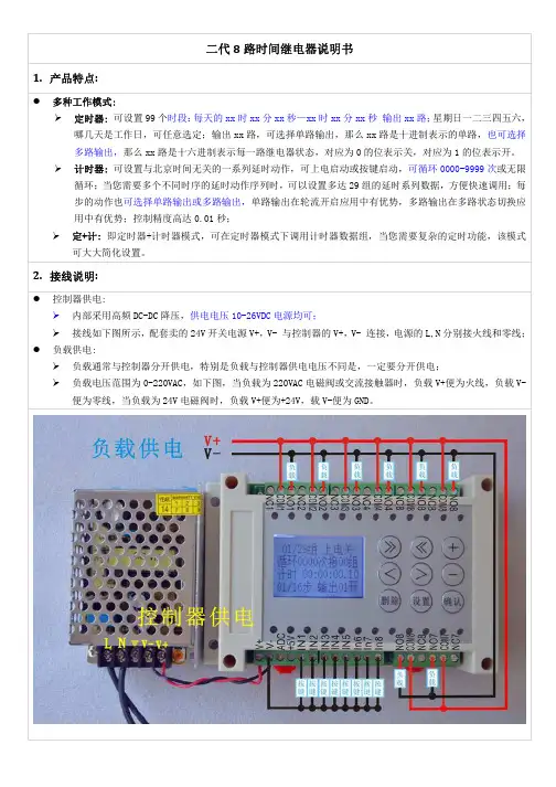
2.接线说明:控制器供电:内部采用高频DC-DC降压,供电电压10-26VDC电源均可;接线如下图所示,配套卖的24V开关电源V+,V- 与控制器的V+,V- 连接,电源的L,N分别接火线和零线; 负载供电:负载通常与控制器分开供电,特别是负载与控制器供电电压不同是,一定要分开供电;负载电压范围为0-220VAC,如下图,当负载为220VAC电磁阀或交流接触器时,负载V+便为火线,负载V-便为零线,当负载为24V电磁阀时,负载V+便为+24V,载V-便为GND。
继电器规格:采用HF3FF,提供常开、常闭输出,最大切换电压:277VAC/30VDC,最大切换电流:10A;外接按键: 每路用一个按键接到V-,按一下触发,IN1—IN8分别启动01—08组计时器数据运行;具体执行什么功能,可通过设置相应的计时器数据实现。
ADC 功能暂时不支持,+5V 可以输出小于100mA 的+5V 电源。
3. 尺寸说明:145*90*40mm4. 功能设置:4.1按键功能:工作状态下,各按键功能定义:“设置”键: 进入设置状态; “删除”键: 刷新屏幕;“插入”键: 启动/暂停运行当前显示计时器数据; “-”键: 启动01组; “>”键: 启动02组; “<”键: 启动03组;“+”键: 计时器复位到01组停止状态;“<<”“>>”键: 上下翻页查看当前计时器数据或定时器数据; 设置状态下下,各按键功能定义:“<<”“>>”键: 上下翻页查看当前计时器数据或定时器数据; “<”“>”键: 左右移动设置光标;“+”“-”键: 光标所指数据递增/递减,输入设置数据; “删除”键: 删除当前显示页数据; “确认”键: 在当前显示页前插入一页; 在上电显示软件版本状态下下,各按键功能定义:“删除”键: 可清空所有定时器和计时器数据,恢复为出厂状态。
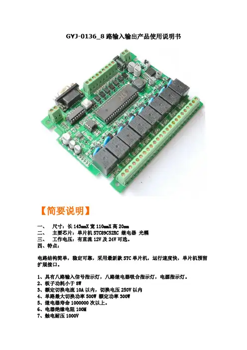
GYJ-0136_8路输入输出产品使用说明书【简要说明】一、尺寸:长143mmX宽110mmX高20mm二、主要芯片:单片机STC89C52RC 继电器光耦三、工作电压:有直流12V及24V可选。
四、特点:电路结构简单,稳定可靠,采用最新款STC单片机,运行速度快,单片机预留扩展接口。
1、具有八路输入信号指示灯,八路继电器吸合指示灯,电源指示灯。
2、板子功耗小于8W3、额定切换电流10A以内,切换电压250V以内4、单路最大切换功率500W 额定功率300W5、继电器寿命1000000次以上。
6、电器绝缘电阻100M7、触电耐压1000V8、继电器最大吸合时间15mS 毫秒9、继电器最大释放时间5mS 毫秒10、工作温度-40度至+70度11、工作湿度40% ~ 80%RH12、8路光电隔离输入,8路光电隔离输出13、8输入低电平有效(即:NPN输入)14、8路输出开关量输出(即:干接点输出)15、具有MAX232通讯和RS485通讯两种模式可选。
16、单片机所有IO口都引出,客户可以自己编程扩展功能17、可以选择使用外部EEPROM 作为存储单元18、电路具有,防反接保护、过流保护、续流保护、压敏保护等19、单片机可以自行更换,可以选择替换型的STC系列单片机20、我们提供电路相关的,原理图、例程、开发环境、下载软件等相关资料适用场合:工业控制、产品开发、项目设计,自动化改造等【标注说明】【接线说明】【输入控制设备】【输出控制设备】【输出举例说明】【输出举例说明】(开关量输出、干接点输出)【专业下载线接线说明】【串口通信说明】也可以通过串口下载【485通信说明】【MAX232与485通信切换说明】【扩展接口说明】(我们会在陆续增加、模拟量输入模块、电流模块、电压模块、无线模块、数码管显示模块、液晶模块、按键模块、PWM模块、模拟量输出模块、wifi模块、CAN模块、IP 模块等等。
)【原理图】(提供PDF格式的原理图及PCB图)更清晰免费提供与此工控板有关的:资料、例程、原理图芯片资料、软件。
8进8出可编程时间继电器原理8进8出可编程时间继电器原理一、引言二、什么是可编程时间继电器? - 继电器的基本概念 - 可编程时间继电器的定义三、8进8出可编程时间继电器的工作原理 - 时间控制模块 - 内部时钟模块 - 时间参数设置模块 - 输入输出模块 - 8进8出继电器模块 - 输入信号检测模块四、可编程时间继电器的应用场景 - 工业自动化领域 - 农业领域 - 家庭智能化五、结语一、引言在现代社会,继电器作为一种重要的电气控制装置,广泛应用于各个领域。
而可编程时间继电器作为继电器的一种高级形式,更加灵活方便,受到了越来越多人的关注。
本文将从浅入深,详细介绍8进8出可编程时间继电器的原理及应用。
二、什么是可编程时间继电器?继电器的基本概念继电器是一种电气控制装置,它利用电磁吸合原理,通过控制小电流将大电流打开或关闭,从而实现电气设备的自动控制。
可编程时间继电器的定义可编程时间继电器是在传统继电器的基础上进行改进,它具备了可以根据指定的时间段和需求进行自动开关的功能。
通过配置预设的时间参数和输入输出模块,可编程时间继电器可以实现复杂的时间控制和设备管理。
三、8进8出可编程时间继电器的工作原理时间控制模块可编程时间继电器内部包含了一个时间控制模块,负责管理时间参数的设置以及计时功能。
###### 内部时钟模块内部时钟模块是可编程时间继电器的核心之一,它通过集成的晶振和时钟电路,提供精确的时间计数和计时功能。
###### 时间参数设置模块时间参数设置模块允许用户自定义时间段及动作方式,可以设置每天的开关时间、周期性执行任务等。
输入输出模块可编程时间继电器还包含了输入输出模块,用于接收输入信号和控制输出信号。
###### 8进8出继电器模块 8进8出继电器模块是可编程时间继电器的核心之一,它通过8个输入和8个输出端口,实现了多路继电器的控制。
用户可以通过设置时间参数,控制特定输入端口与对应输出端口之间的触发关系。
USB数字量IO开关控制卡8路隔离数字量输入8路固态继电器输出USB5529 数据采集卡硬件使用说明书阿尔泰科技发展有限公司产品研发部修订阿尔泰科技发展有限公司目录目录 (1)第一章功能概述 (2)第一节、产品应用 (2)第二节、DI 数字量输入功能 (2)第三节、DO 数字量输出功能 (2)第四节、其他指标 (2)第二章元件布局图及简要说明 (3)第一节、主要元件布局图 (3)第二节、主要元件功能说明 (3)一、信号输入输出连接器 (3)二、物理ID 拨码开关 (3)三、指示灯 (4)第三章信号输入输出连接器 (5)第一节、数字量信号输入连接器定义 (5)第二节、数字量信号输出连接器定义 (5)第四章各种信号的连接方法 (7)第一节、DI 数字量信号输入的连接方法 (7)一、干接点信号输入的连接方法 (7)二、湿接点信号输入的连接方法 (7)第二节、DO 数字量信号输出的连接方法 (7)第五章产品的应用注意事项、校准、保修 (9)第一节、注意事项 (9)第二节、保修 (9)USB5529 数据采集卡硬件使用说明书版本:6.0.11第一章功能概述信息社会的发展,在很大程度上取决于信息与信号处理技术的先进性。
数字信号处理技术的出现改变了信息与信号处理技术的整个面貌,而数据采集作为数字信号处理的必不可少的前期工作在整个数字系统中起到关键性、乃至决定性的作用,其应用已经深入到信号处理的各个领域中。
实时信号处理、数字图像处理等领域对高速度、高精度数据采集卡的需求越来越大。
ISA 总线由于其传输速度的限制而逐渐被淘汰。
我公司推出的基于 PCI 总线、USB 总线等数据采集卡综合了国内外众多同类产品的优点,以其使用的便捷、稳定的性能、极高的性价比,获得多家客户的一致好评,是一系列真正具有可比性的产品,也是您理想的选择。
第一节、产品应用USB5529 卡是一种基于USB 总线的数据采集卡,可直接插在计算机的 USB 接口上,构成实验室、产品质量检测中心等各种领域的数据采集、波形分析和处理系统。
8进8出时间继电器使用手册
一、产品概述
8进8出时间继电器是一种电气控制元件,用于在特定时间间隔内控制电路的接通和断开。
它广泛应用于各种自动化设备和智能控制系统,用于实现精确的时间延迟和定时操作。
二、产品特点
1. 8个输入通道和8个输出通道,可同时控制多个电路的接通和断开。
2. 可设置多种时间延迟模式,以满足不同应用需求。
3. 具有手动控制功能,方便用户进行测试和调试。
4. 采用先进的微处理器技术,确保高精度和稳定性。
5. 安装简单,易于维护。
三、使用方法
1. 连接电源和信号线:将电源线连接到继电器标有“POWER”的端子,并将信号线连接到相应的输入端子。
2. 设定时间延迟:通过控制面板或编程软件设置所需的时间延迟,以控制电路的接通和断开时间。
3. 启动控制:当时间到达设定值时,相应的输出端子将自动接通或断开,从而实现定时控制。
4. 手动控制:如需进行手动测试或调试,请使用控制面板上的手动模式按钮或编程软件进行操作。
5. 参数设置:根据实际需求,可通过控制面板或编程软件调整各种参数,如输入信号类型、时间单位等。
6. 故障排除:如遇故障,请检查电源和信号线是否连接正确,以及时间继电器的设定是否符合要求。
如仍无法排除故障,请联系专业技术人员进行维修。
四、注意事项
1. 在使用过程中,请勿随意更改继电器的内部接线,以免造成损坏或安全隐患。
2. 在连接电源和信号线时,请确保电源电压与继电器要求相符,避免过载或损坏设备。
3. 在设定时间延迟时,请确保数值准确,避免因设定错误导致设备异常工作。
PCI总线8路开关量输入8路开关量驱动输出24路脉冲计数板IO703使用说明书北京瑞博华控制技术有限公司8路开关量输入8路开关量驱动输出24路脉冲计数板IO703一、性能特点:1.采用功率驱动芯片MC1413实现开关量驱动输出2.功率驱动为集电极开路输出3.开关量输出的电流,最大达200mA4.输入可以是开合信号,也可以是电平信号5.复位后,输出低电平,输出三极管断开6.脉冲计数通道中,外部时钟经过斯密特触发器整形,可以对各种脉冲信号进行计数处理,脉冲信号输出,采用驱动输出,大大提高了驱动能力,驱动电流大于8mA.二、功能与指标1、通道数:8路开关量输入,8路开关量输出,24路脉冲计数通道2、输入:断开或闭合输入;电平输入3、电平:输入为TTL电平,输出为集电极开路输出,有微弱上拉4、总线方式:PCI总线5、接头方式:DB37(孔式),IDC34的插针6、软件环境:Win2000/WIN98/WIN95/DOS7、工作温度:0-70℃三、工作原理简介开关量输出的简图如图1所示。
用户电源负载接线端控制信号MC1413地图1 开关量输出接线示意图用户的负载接线方法如图1所示,只需将负载接在用户电源与J37上对应的接线端子上即可。
注意,当用户负载电阻太小时,应注意接限流电阻,以防止输出电流过大,当用户使用的是感性负载时,应注意加限压保护。
开关量输出有微弱的上拉作用,上拉电阻是20K欧,可以用于电平输出,由于该电阻较大,因此基本上可以看作是集电极开路输出,可以直接接继电器。
输入信号的接线示意图如图2所示,输入信号通过插针J1接入,输入接线端子通过4.7千欧的电阻上拉,上拉的电平为+5伏。
用户可以采用电平输入方式以及断开与闭合输入方式(开合方式)。
开合输入方式的方法是:将开关的一端接地,另一端接接线端子,当开关断开时,输入状态为高电平,当开关闭合时,输入状态为低电平。
接线端子缓冲器+5伏4.7千欧图 2 输入接线示意图9片8253分别标记为8253-0,8253-1,8253-2, 8253-3,8253-4,8253-5,8253-6,8253-7和8253-8,每块芯片有3个计数器,分别标记为0、1、2,这样,27路脉冲计数信号分别标记为00、01、02、10、11、12、20、21、22、30、31、32、40、41、42、50、51、52、60、61、62、70、71、72、80、81、82。
Contents CHAPTER 1General Information (1)1.1 Introduction (2)1.2 Features (3)1.3 Applications (4)1.4 Specifications (4)1.5 Pin Assignments (7)1.6 Block Diagram (8)CHAPTER 2 Installation (9)2.1 Initial Inspection (10)2.2 Unpacking (10)2.3 Jumper Settings (11)2.4 Installation Instructions (14)CHAPTER 3Digital Input Programming (15)3.1 Overview (16)3.2 Dry Contact Support for Each IDI (16)3.3 Digital Filter (17)3.4 Pattern Match (18)3.5 Change of Input State (19)3.6 Counter (19)CHAPTER 4Relay Output (21)CHAPTER 5Pulse-Width Modulation (23)5.1 Overview (24)5.2 Introduction to PWM (24)APPENDIX ARegister Structure and Format (25)A.1 Overview (26)A.2 OMB0 ~ 3: Outgoing Mailbox Bytes (26)A.3 IMB0 ~ 3: Incoming Mailbox Bytes (27)A.4 INTCSR0 ~ 3: Interrupt Control/Status Register (27)A.5 Flow Chart (29)APPENDIX BDescription of Command Codes (31)COMMAND CODE: 00 (32)PURPOSE: Clears IMB2’s Contents to 0 (32)COMMAND CODE: 01 (33)PURPOSE: Enable/Disable Relay Outputs (33)COMMAND CODE: 02 (34)PURPOSE: Read the Relay Status (34)COMMAND CODE: 07 (34)PURPOSE: Read the Current Status (34)COMMAND CODE: 0E, 0F (36)PURPOSE: Read the PCI-1760 Firmware/Hardware Version (36)COMMAND CODE: 10, 11, 12, 13 (37)PURPOSE: Sets the “High” and “Low” Period Value of the PWMn (37)COMMAND CODE: 14, 15 (38)PURPOSE: Sets PWMn's Burst Count (38)COMMAND CODE: 1F (39)PURPOSE: Enables/Disables PWM Outputs (39)COMMAND CODE: 20 (40)PURPOSE: Enables/Disables the Digital Filter Function of IDI (40)COMMAND CODE: 21 (41)PURPOSE: Enables/Disables the Pattern Match Function of IDI (41)COMMAND CODE: 22PURPOSE: Sets the Pattern Match Value of IDI (43)COMMAND CODE: 23, 24 (44)PURPOSE: Enable/Disable the Rising/Falling Edge Detection Function of IDIn (44)COMMAND CODE: 28 (45)PURPOSE: Enables/Disables the UP Counter Function of IDI (45)COMMAND CODE: 29 (46)PURPOSE: Resets the UP Counter of IDIn to Its Reset Value (46)COMMAND CODE: 2A (47)PURPOSE: Enables/Disables the UP Counter Overflow Interrupt Function of IDIn (47)COMMAND CODE: 2B (48)PURPOSE: Enables/Disables the UP Counter Value Match Interrupt function of IDI (48)COMMAND CODE: 2C (49)PURPOSE: Sets the Count Edge of IDI’s UP Counter (49)COMMAND CODE: 2F (50)PURPOSE: Reads IDIn's UP Counter Current Value (50)COMMAND CODE : 30~3F (51)PURPOSE : Sets the Sampling Number for the Effective “High/Low”Period of IDIn (51)COMMAND CODE : 40~47 (53)PURPOSE : Sets IDIn’s UP Counter Reset Value (53)COMMAND CODE: 48~4F (54)PURPOSE: Set IDIn’s UP Counter Match Value (54)COMMAND CODE : 60 (56)PURPOSE : Reads Interrupt Flags (56)COMMAND CODE: 61 (57)PURPOSE: Reads IDI Edge Change Flags (57)COMMAND CODE: 62 (58)PURPOSE: Reads the IDI's Counter Overflow/Value Match Flags (58)APPENDIX CPCI-1760 Command Code Quick Reference (60)1.1IntroductionThe most common method of interfacing a microcomputer system,such as the PC with an industrial process, is by using programmabledigital input and output registers. The computer can write data intodigital output registers, treating them as I/O ports. The output fromthese registers can then be wired to an interface device, such as arelay. Thus, by sending data to an output register, it is possible toactivate and deactivate a relay. The relay could, in turn, control, forexample, an electric motor.Similarly, a digital input register can be considered as an I/O port that has wires attached to individual bit locations. When read, the datareflects the states of signals on the wires. Digital input registers canbe used to monitor incoming signals. For example, to determinewhether a switch is open or closed, the switch can be wired to theinput of a digital input register.The PCI-1760 Relay Actuator & Isolated Digital Input Card is a PCadd-on card for the PCI bus, which was designed with this idea inmind. This card offers the user 8 opto-isolated digital inputs withisolation protection of 2500 V DC for collecting digital signals undernoisy environment, 8 relay actuators for serving as ON/OFF controldevices or small power switches, and 2 isolated PWM (Pulse WidthModulation) outputs for user's specific applications.Each isolated digital input supports both dry contact and wet contact, designated by jumper settings, so that it can easily interface withother devices. Additionally, for easy monitoring, each relay isequipped with one red LED to reflect its ON/OFF status.Digital filter eliminates unexpected inputnoiseThe PCI-1760 includes a programmable digital filter on each digitalinput channel to eliminate the unexpected signal or noise from thecard's inputs. When the digital filter is enabled, the state of thecorresponding input channel will not update immediately until onehigh/low signal has lasted for a period which is programmed by theuser.2PCI-1760 User's ManualInterrupt function ensures faster systemresponseThe PCI-1760 provides a ìPattern Matchî interrupt function for thedigital input channels. The card monitors the state of some or all ofthe input channels and compares it with a pre-set pattern. When thereceived state matches the pre-set pattern, the card generates aninterrupt signal to the system.The ìChange of Input Stateî interrupt function also monitors the state of the input channels. When any input changes its state, the cardinterrupts the system to handle this event.Up event counter for each DIEach isolated digital input channel is connected to a 16-bit UP eventcounter. A counter will increment by 1 whenever it reads either arising-edge (low to high) or a falling-edge (high to low) input signalwith the maximum frequency of 500 Hz. When the counter overflowsor reaches a pre-set value (programmed by software), it generates aninterrupt signal to the PC.1.2Features•8 opto-isolated digital input channels•8 relay actuator output channels• 2 opto-isolated PWM outputs•LED indicators to show activated relays•Jumper selectable dry contact/wet contact input signals•16-bit Up counter function for each DI•Programmable digital filter function for each DI•Pattern match interrupt function for each DI•Change of input state interrupt function for each DIChapter 1 General Information 31.3Applications•Digital signal and contact status monitoring•Industrial On/Off control•Signal switching•External relay driving1.4SpecificationsIsolated Digital Input•Channels: 8•Opto-isolator: PC354•Input voltage: 5 ~ 12 VHigh: > 4.5 VLow: < 1.0 VUncertain: 1.0V ≤ Vin ≤ 4.5V•Input resistance: 1k Ω @ 1/4 W•Isolation voltage: 2500 V DC•Digital Filter:Minimum effective High input period ≥ [(2 ~ 65535) x 5 ms] + 5 msMinimum effective Low input period ≥ [(2 ~ 65535) x 5 ms] + 5 ms•16-bit UP counter:Maximum effective input frequency: 500HzMinimum High period ≥ 1 msMinimum Low period ≥ 1 ms4PCI-1760 User's ManualRelay Output•Channels: 8•Relay type: single-pole double-throw (SPDT, Form C),but RE2 ~ RE7 are hooked up as single-pole single-throw (SPST)•Output type:RE0 and RE1: NC and NO outputsRE2 ~ RE7: NC or NO outputs (selected by jumper)•Rating contact load: 120 V AC @ 0.5 A or 30 V DC @ 1 A•Contact resistance: less than 100 mΩ initially•Dielectric strength:Coil to contacts (deenergized): 1500 Vrms (1 minute)Between open contacts (deenergized & energized):1000 Vrms (1 minute)•Life expectancy:200,000 operations @ 0.5 A 120 V AC500,000 operations @ 1.0 A 30 V DC•Operating & Releasing time:Operating time: 5 ms max.Releasing time: 5 ms max.Isolated PWM output•Channels: 2•Isolation voltage: 2500 V DC•Scaling resolution: 16 bits (100 µs for each step)High period = [(1 ~ 65535) x 100 µs ] ± 50 µs (max.)Low period = [(1 ~ 65535) x 100 µs ] ± 50 µs (max.)•Output level:High: (5 ± 0.5) VLow: < 0.8 VChapter 1 General Information 5General•Power consumption: +5V @ 450 mA (typical), 850 mA (max.)•Operating temperature: 0 ~ +60° C (32 ~ 140° F)(refer to IEC 68 - 2 - 1, 2)•Storage temperature: -20 ~ +70° C (-4 ~ 158° F)•Operating humidity: 5 ~ 95%RH non-condensing(refer to IEC 68-2-3)•MTBF: over 117,317 hrs @ 25°C, grounded, fixed environmentPhysical•Connector: One 37-pin D-type connector•Dimensions: 175 x 100 mm (6.9" x 3.9")6PCI-1760 User's ManualIG N DID I7-ID I7+ID I6-ID I5-ID I4-ID I3-ID I2-ID I1-ID I0-ID I6+ ID I5+ ID I4+ ID I3+ ID I2+ ID I1+ ID I0+P W M0P W M1R7_O U T R6_O U T R5_O U T R4_O U T R3_O U T R2_O U TR7_C O M R6_C O M R5_C O M R4_C O M R3_C O M R2_C O M R1_N O R1_N C R1_C O MR0_C O M R0_N C R0_N O1.5Pin AssignmentsDescription of pin use:IGND: Isolated Ground for PWMoutputs and dry contact wiring ofIDIIDIn+(n = 0 ~ 7):Isolated digital input+IDIn- (n = 0 ~ 7):Isolated digital input-PWMn (n = 0, 1):Isolated PWM outputRn_OUT (n = 2 ~ 7):Normally Open/Closed pin ofRelay outputRn_NO (n = 0 ~ 1):Normally Open pin of RelayoutputRn_NC (n = 0 ~ 1):Normally Closed pin of RelayoutputRn_COM (n = 0 ~ 7):Common pin of Relay outputChapter 1 General Information 71.6Block DiagramFigure 1.1PCI-1760 Block Diagram 8PCI-1760 User's Manual2.1 Initial InspectionBefore installing the PCI-1760, check the card for visible damage.We have carefully inspected the card both mechanically andelectrically before shipment. It should be free of marks and inperfect order upon receipt.As you unpack the PCI-1760, check it for signs of shipping damage(damaged box, scratches, dents, etc.). If it is damaged or fails to meetspecifications, notify our service department or your local salesrepresentative immediately. Also, call the carrier immediately andretain the shipping carton and packing materials for inspection by the carrier. We will then make arrangements to repair or replace the unit.2.2 UnpackingThe PCI-1760 contains components that are sensitive and vulnerableto static electricity. Discharge any static electricity on your body toground by touching the back of the system unit (grounded metal)before you touch the board.Remove the PCI-1760 card from its protective packaging by grasping the card's rear panel. Handle the card only by its edges to avoid static discharge which could damage its integrated circuits. Keep theantistatic package. Whenever you remove the card from the PC,protect the card by storing it in this package.Y ou should also avoid contact with materials that hold static electrici-ty such as plastic, vinyl and styrofoam.Check the product contents inside the packing. There should be onecard, one CD-ROM, and this manual. Make sure nothing is missing. 10PCI-1760 User's Manual2.3Jumper SettingsWe designed the PCI-1760 with ease-of-use in mind. It is a "plug andplay" card, i.e. the system BIOS assigns the system resources such asbase address and interrupt automatically. There are only threefunctions with 15 jumpers to be set by the user (see Figure 2.1 andTable 2-1). Y ou may refer to the figure below for help in identifyingcard components.Figure 2.1 Location of jumpers and relaysChapter 2 Installation 11Table 2.1: Summary of jumper settingsSetting dry/wet contact connection foreach DIEach of the 8 isolated digital input channels accepts either drycontact or 5 ~ 12 V DC wet contact inputs according to the correspond-ing jumper settings (see Table 2.2). The default setting for each IDI is dry contact. For detailed information, please refer to Chapter 3.Setting relay outputs to be NC/NO6 relay outputs, RE2 ~ RE7, are single-pole single-throw (SPST),which can be jumper set as either nornally open (NO) or normallyclose (NC) (see Table 2.3). The default settings for RE2 ~ RE7 arenormally open. For detailed information, please refer to Chapter 4.Note!: RE0 and RE1 are Form C relays12PCI-1760 User's ManualChapter 2 Installation 13Table 2.2: IDI and corresponding jumperTable 2.3: Relay output and corresponding jumperSetting the time to reset the relay outputsSome users will want the capability of clearing each relay output when the system (or PC) issues a reset signal on the PCI bus. Some users will want to clear their relays only as part of system power-on.The PCI-1760 satisfies both these needs by providing jumper JP14.Depending on the application, this capability may allow relay outputs to be "OFF" without requiring a complete shutdown of processes controlled by the card.Complete loss of power to the chip clears the chip memory. Thus, no matter how JP14 is set, if the power to the PCI-1760 is disconnected,the relay initial power-on state will be "OFF" (NC or NO, depending on the user's settings).2.4Installation InstructionsThe PCI-1760 can be installed in any PCI slot in a computer. Howev-er, to avoid any mistakes or dangerous conditions, please refer to your computer user's manual before you follow the installation procedurebelow:1. Turn off your computer and any accessories connected to thecomputer.Warning!TURN OFF your computer power supply wheneveryou install or remove any card, or connect anddisconnect cables.2. Disconnect the power cord and any other cables from the back ofthe computer.3. Remove the cover of the computer.4. Select an empty 5 V PCI slot. Remove the screw that secures theexpansion slot cover to the system unit. Save the screw to securethe interface card retaining bracket.5. Carefully grasp the upper edge of the PCI-1760. Align the hole inthe retaining bracket with the hole on the expansion slot and alignthe gold striped edge connector with the expansion slot socket.Press the card into the socket gently but firmly. Make sure the cardfits the slot tightly.6. Secure the PCI-1760 by screwing the mounting bracket to the backpanel of the computer.7. Attach any accessories (37-pin D type cable, wiring terminal board,etc.) to the card.8. Replace the cover of your computer. Connect the cables youremoved in step 2.9. Turn the computer power on.14PCI-1760 User's Manual16PCI-1760 User's ManualID InID In : Isolated digital input (n = 0 ~ 7)3.1 OverviewThe PCI-1760 provides 8 opto-isolated digital input channels with 2500V DC isolation. In addition to supporting both dry and wetcontacts, this card provides "Digital Filter", "Pattern Match", "Change of State" and 16-bit UP counter functions for each digital input channel. All these functions are optional. Users can enable/disable each function to fit their applications. Figure 3.1 is a simplified function logic block diagram for the PCI-1760's digital inputs. The following sections will introduce these useful functions.Figure 3.1: PCI-1760 function logic block diagram3.2 Dry Contact Support for Each IDIEach of the 8 isolated digital input channels accepts either dry contact or 5 ~ 12 V DC wet contact inputs as determined by the corresponding jumper settings (see Table 2.1 and Table 2.2). Dry contact capability allows an input channel to respond to changes in an external circuit (e.g., the closing of a switch in the external circuit)when no voltage is present in the external circuit. Figure 3.2 shows the internal and external circuitry, with both wet and dry contact components connected as an input source for one of the PCI-1760's isolated digital input channels.Note!:The default settings of jumpers JP0 ~ JP7 are drycontact, just as shown in Figure 3.2.Figure 3.2: Dry and wet contacts3.3 Digital FilterEach digital input channel has a programmable digital filter foreliminating unexpected signals and noise from the card circuitry. The user can set different digital filtering parameters for each inputchannel in different applications. The following is a functionaldescription of the digital filter.1.When a digital filter is enabled, the PCI-1760 will sample thesignals at the enabled input channel at a 5 ms sampling rate.2.When a high or low signal is present at a digital input channelwhose digital filter function is enabled, the signal will be filteredout as noise unless it lasts for an effective period.3.The effective period is determined by multiplying the samplingrate (5 ms) by the sampling number (2 ~ 65535) chosen by the user,i.e.Effective period = Sampling number x 5 ms.Chapter 3 Digital Input Programming 17Note!: The sampling numbers for High and Low signals can be different. For example, assuming that the samplingnumbers are 10 for a High signal and 15 for a Low signal,the state of the digital input channel will update if a highsignal lasts for 50 ms or more, or a low signal lasts for75 ms or more.Note!: For digital input channels whose digital filter functions are not enabled, the PCI-1760 samples the signals at theseinput channels at a 100 µs sampling rate and immediate-ly updates the state of these input channels when thesignal changes.3.4 Pattern MatchThe PCI-1760 provides a pattern match interrupt function on itsdigital input channels. It monitors the status of the enabled inputchannels, and compares these with a pre-set pattern. When the actualstate matches the pre-set pattern, the PCI-1760 delivers an interruptsignal to the system. This function releases the CPUfrom the burdenof polling all the I/O points, enabling a PC to handle more I/O pointswith higher performance. An example follows:Example 3.1 Assume that the pattern match function is enabled forthe isolated digital input channels IDI1, IDI2, IDI6 and IDI7 (i.e. IDI0, IDI3, IDI4, and IDI5 are ignored during the pattern match process).Then the user can set the pattern match values for the enabled inputchannels. The table below shows one possibility.In thes example, when IDI1, IDI2 and IDI7 are high and IDI6 is low, an interrupt signal will be generated. No matter what the status of IDI0,IDI3, IDI4 and IDI5 are, these will not affect the result.18PCI-1760 User's Manual3.5 Change of Input StateThe PCI-1760 also provides a change of state interrupt function oneach digital input channel allowing users to monitor the status of theenabled digital input channels more efficiently. When one of theenabled channels changes its state, the PCI-1760 delivers an interrupt signal to the system to handle this event. The function can be set togenerate an interrupt for a rising edge signal, a falling edge signal, ora signal with both edges, depending on user application require-ments. The following is an example.Example 3.2 Assume that the change of input state function for theisolated digital input channels IDI1, IDI2, IDI6 and IDI7 is enabled(i.e. the signals at IDI0, IDI3, IDI4 and IDI5 are ignored by the changeof state function). When a change of state occurs in IDI1, IDI2, IDI6or IDI7, an interrupt signal is sent to the system.3.6 CounterEach digital input channel is connected to a 16-bit UP event counterwith a maximum frequency of 500 Hz. Each counter is enabled ordisabled by software. The following describes its major functions:1. Counter reset valueEach counter has its own reset value. When most cards are poweredon, the start-up value of a counter is zero, but in the PCI-1760, usersare allowed to set the reset value to a number between 0 and 65535.This is a very useful feature when one of the counters needs to bestarted from a non-zero number.2. Counter value match interruptAll eight counters also have a counter value match interrupt function.When this interrupt function is enabled, an interrupt signal will begenerated if the counter value reaches a pre-set counter match value.The counter will continue to count until an overflow occurs, then itwill go back to its reset value zero and continue the counting process.Chapter 3 Digital Input Programming 1920PCI-1760 User's ManualQ3. OverflowAn overflow will occur when the counter reaches its maximum value,65535, and an interrupt signal will be generated when this function is enabled.4. Count edgeA user can set each individual channel's counter to count either falling edge (high-to-low) or rising edge (low-to-high) signals. The appropriate setting depends on the initial state of the input signals; if they are low, a rising edge setting would be appropriate.The following figure illustrates counter operation. Counting starts from the counter reset value and continues until it reaches its match value. At that time, an interrupt will also be generated. Afterwards,the counter continues to count until it reaches the maximum capacity of 65535, at which time an overflow interrupt is generated and the counter is reset to its reset value, and continues to count.Figure 3.3: Example for counter operation22PCI-1760 User's ManualThe PCI-1760 provides 8 relay outputs to serve as On/Off control devices. The user can enable and disable each relay output using software commands. For easy monitoring, each relay output isequipped with one red LED to show its On/Off status.Note!: Please refer to Appendix B for more information aboutrelay output software programming.Of these eight relays, two relays (RE0 and RE1) are single-poledouble-throw (SPDT, Form C) and six (RE2 ~ RE7) are single-pole single-throw (SPST), which can be set as either normally open (NO) or normally closed (NC) via jumper settings. The following figureillustrates the structures and connections of the relay outputs.Note!: The default setting for RE2 ~ RE7 is narmally open (NO).Please refer to Chapter 2 for detailed information con-cerning the setting of jumpers.C O MN C /N OREn (n =2 ~ 7)REn (n = 0, 1)JPn+6Figure 4.1: Relay structures and connections24PCI-1760 User's Manual5.1 OverviewThe PCI-1760 also provides two PWM (Pulse-Width Modulation)outputs with 2500 V DC isolation. Each PWM output can be indepen-dently enabled or disabled using software commands.5.2 Introduction to PWMA pulse-width modulated waveform is created when the High and Low periods of a periodic rectangular signal are varied. In the PCI-1760, the user can individually set each channel’s High and Low periods for from 1 to 65535 units (1 unit = 100µs), depending on his needs.The user can also define the “burst count”, the number of cycles generated in each PWM channel. It can be a specific number of cycles or a non-stop cycle. If not a non-stop cycle, the predefined number of cycles must be between 1 and 65535.When the user enables a PWM output, the PCI-1760 will check the PWM burst count value first, If the burst count value is zero, the PWM output will be non-stop. If the burst count value is non-zero, the PWM will output the number of cycles which equals the burst count value,then stop. If the user wants to output another pulse chain, he has to set a new burst count value, then enable the PWM again.Note!: Please refer to Appendix B for more information aboutPWM software programming.L o w p e rio d1 ~ 65535 u n its H ig h p e rio d 1 ~ 65535 u n itsA.1 OverviewThe PCI-1760 is delivered with an easy-to-use 32-bit DLL driver foruser programming under the Windows 95/98/NT operating system. To program the PCI-1760, users are advised to use the 32-bit DLL driverprovided by Advantech to avoid the complexity of low-level pro-gramming by register.When it is necessary to program the PCI-1760 at a register level, themost important consideration is to understand the function of thecard’s registers. The PCI-1760 occupies 128 bytes in the PC’s I/Ospace. In general operations, it only requires 8 I/O spaces, 4 forwriting commands and 4 for reading commands. To enable/disablethe interrupt function, the PCI-1760 requires another 4 I/O spaces toread/write. The address of each register is specified as an offset fromthe card’s base address.A.2OMB0 ~ 3: Outgoing Mailbox BytesWrite OMB3OMB2OMB1OMB0 Address (Hex.)Base + 0x0F Base + 0x0E Base + 0x0D Base + 0x0COMB3:This byte is not currently used. It is reserved for future use.Its value must be 0x00 unless 16 or 32-bit command codesare used.OMB2:Writes a command code (0x00 ~ 0xFF) to the PCI-1760. For detailed descriptions of the command codes, please refer toAppendix B.OMB1:The High byte of the parameter for the command in OMB2OMB0:The Low byte of the parameter for the command in OMB2Note!:If a command needs one parameter, users should write the parameter (OMB1 and/or OMB0) first, then write thecommand code to OMB2.26PCI-1760 User's ManualAppendix A Register Structure and Format 27A.3IMB0 ~ 3: Incoming Mailbox BytesIMB3:This byte shows IDI (Isolated Digital Inputs) current values.This status will be updated every 100µs by the PCI-1760’s on-board monitor system.IMB2:This byte shows the current command status. When the userwrites a command code in OMB2, IMB2’s status will beupdated to match OMB2 if the command code is successfully received by the PCI-1760.IMB1:The High byte of the feedback data for the command inOMB2IMB0:The Low byte of the feedback data for the command inOMB2A.4INTCSR0 ~ 3: Interrupt Control/Status RegisterThere are 4 interrupt sources (IDI pattern match, IDI state change, IDI counter value match and IDI counter overflow) provided by the PCI-1760. To enable/disable the interrupt function, the PCI-1760 requires another 4 I/O spaces to read/write.Read IMB3IMB2IMB1IMB0Address (Hex.)Base + 0x1FBase + 0x1EBase + 0x1DBase + 0x1CID I p attern m atch ID I sta te c han geID I co unte r m atch ID I co unte r overflowE na ble / D is able by the com m an d co de E na ble / D is able by IN T C S R 1 b it 5P C INTRead/Write INTCSR3INTCSR2INTCSR1INTCSR0Address (Hex.)Base + 0x3B Base + 0x3A Base + 0x39Base + 0x38INTCSR3: Must be 0 unless 16 or 32-bit command codes are usedINTCSR2: This byte shows the interrupt status (read only)bit 0: Outgoing mailbox Interrupt (not available now)bit 1: Incoming mailbox Interrupt (not available now)bit 2 ~ 5: Must be 0bit 6: On-board interrupt statusbit 7: Interrupt assertedINTCSR1: To enable/disable the interrupt functionbit 0 ~ 4: Must be 0bit 5: To enable/disable the on-board interrupt functionbit 6 ~ 7: Must be 0INTCSR0: Must be 0 unless 16 or 32-bit command codes are used 28PCI-1760 User's ManualA.5 Flow ChartTo write a command or confirm the command status, please follow the flow chart below.Appendix A Register Structure and Format 2930PCI-1760 User's ManualCOMMAND CODE: 00PURPOSE: Clears IMB2 s Contents to 0OMB3OMB2OMB1OMB00x000x00N/A N/A OMB2: Command codeIf successfulIMB3IMB2IMB1IMB00x00 ~ 0xFF0x00XX XX IMB3: IDI current valuesIMB2: Command code echoThe purpose of this command is to clear IMB2’s contents by echoing the command code “00” from OMB2. Users can detect when acommand has been executed by reading its echo in IMB2. When agiven command is executed twice in a very short period, it can bevery difficult to identify the two separate commands just by readingthe command code in IMB2. A simple solution to this problem is towrite a command code “00” between the two identical commands inOMB2. The command code “00” clears the first command code inIMB2 and lets the user clearly recognize execution of the secondcommand. Of course, if a user does not need to distinguish eachseparately executed command, the insertion of the command code“00” between the two identical commands is not necessary.32PCI-1760 User's Manual。
【简要说明】【标注说明】【接线说明】【输入控制设备】【输出控制设备】【输出举例说明】(开关量输出、干接点输出)【上位机控制软件】提供VB程序和下位机程序【测试程序简说协议】通过串口助手发送命令控制 (文本模式)单片机与PC机采用9针串口,MAX232通讯,波特率默认为9600. 单片机接收PC机发送的ASC||码(文本模式)表如下:01、全开:PC发送'I';全关:PC发送'i';03、1路开:PC发送'A';1路关:PC发送'a';04、1路开:PC发送'B';2路关:PC发送'b';05、3路开:PC发送'C';3路关:PC发送'c';06、4路开:PC发送'D';4路关:PC发送'd';07、5路开:PC发送'E';5路关:PC发送'e';08、6路开:PC发送'F';6路关:PC发送f';【UART通信说明】也可以TTL下载【485通信说明】#include<reg52.h> //库文件#include <intrins.H>#include<EEPROM.h>#define uchar unsigned char//宏定义无符号字符型sbit K1=P1^0;sbit K2=P1^1;sbit K3=P1^2;sbit K4=P1^3;sbit K5=P1^4;sbit K6=P1^5;sbit K7=P1^6;sbit K8=P1^7;uchar dat;uchar t,r,ii;uchar add; //掉电保持485的地址uchar j=0;bit flag_zx=0;uchar sendBuf[10]; //发送缓冲区uchar receBuf[10]; //接收缓冲区bit busy;bit bz1=0;bit bz2=0;bit bz3=0;bit bz4=0;bit bz5=0;bit bz6=0;bit bz8=0;/********************************************************************延时函数*********************************************************************/ void delay(uchar t){uchar i,j;for(i=0;i<t;i++){for(j=13;j>0;j--);{ ;}}}/******************************************************************** 功能:串口初始化,波特率9600,方式1*********************************************************************/ void Init_Com(void){TMOD = 0x20;PCON = 0x00;SCON = 0x50;TL1 = 0xFd;TR1 = 1;ES=1;EA=1;}/****************发送函数*********************/void senduart2(){//RS485_DIR=1;SBUF=sendBuf[0];while(!TI);TI=0;SBUF=sendBuf[1];while(!TI);TI=0;SBUF=sendBuf[2];while(!TI);TI=0;SBUF=sendBuf[3];while(!TI);TI=0;SBUF=sendBuf[4];while(!TI);TI=0;}/*****************清空发送缓冲区*************************/ void clear_receBuf(){uchar i;for(i=0;i<5;i++){receBuf[i]=0;}}/********************************************************************主函数*********************************************************************/void main(){Init_Com();//串口初始化add = EEPROMReadByte(0);//add = 0X00;while(1){/*uchar k;k=100;if((IN0==0)&&(bz1==0)){delay(k);if(IN0==0){delay(k);K1=!K1;bz1=1;}}if((bz1==1)&&(IN0==1)){delay(k );bz1=0;}if((IN1==0)&&(bz2==0)){delay(k);if(IN1==0){delay(k);K2=!K2;bz2=1;}}if((bz2==1)&&(IN1==1)){delay(k );bz2=0;}if((IN2==0)&&(bz3==0)){delay(k);if(IN2==0){delay(k);K3=!K3;bz3=1;}}if((bz3==1)&&(IN2==1)){delay(k );bz3=0;}if((IN3==0)&&(bz4==0)){delay(k);if(IN3==0){delay(k);K4=!K4;bz4=1;}}if((bz4==1)&&(IN3==1)){delay(k );bz4=0;}if((IN4==0)&&(bz5==0)){delay(k);if(IN4==0){delay(k);K5=!K5;bz5=1;}}if((bz5==1)&&(IN4==1)){delay(k );bz5=0;}if((IN5==0)&&(bz6==0)){delay(k);if(IN5==0){delay(k);K6=!K6;bz6=1;}}if((bz6==1)&&(IN5==1)){delay(k );bz6=0;}if((IN6==0)&&(bz7==0)){delay(k);if(IN6==0){delay(k);K7=!K7;bz7=1;}}if((bz7==1)&&(IN6==1)){delay(k );bz7=0;}if((IN7==0)&&(bz8==0)){delay(k);if(IN7==0){delay(k);K8=!K8;bz8=1;}}if((bz8==1)&&(IN7==1)){delay(k );bz8=0;}/********************************************************************接收数据判断函数*********************************************************************/if(RI) //如果有接收{RI=0; //接收标志清零receBuf[r++&0x0F]=SBUF; //把接受的数据存储到BUT数组中if(receBuf[0]!=0xaa){r=0;}if(r>=5){ r=0;flag_zx=1;}}if(flag_zx==1){flag_zx=0;//0 1 2 3 4//起始位地址位功能位数据位结束位if((receBuf[0]==0xaa)&&(receBuf[4]==0xbb)&&(receBuf[1]==add)) //如果开始位和结束位,还有地址都正确,进行下一步判断{if(receBuf[2]==0x01) //修改板子地址{add=receBuf[3];EEPROMSectorErase(0);//擦除扇区EEPROMWriteByte(0,add);//写入新的地址sendBuf[0]=0xaa;sendBuf[1]=add;sendBuf[2]=0x00;sendBuf[3]=add;sendBuf[4]=0xbb;senduart2();}else if(receBuf[2]==0x02) //打开单路继电器{switch(receBuf[3]){case 0x01: K1=0; break;case 0x02: K2=0; break;case 0x03: K3=0; break;case 0x04: K4=0; break;case 0x05: K5=0; break;case 0x06: K6=0; break;case 0x07: K7=0; break;case 0x08: K8=0; break;default:break;}}else if(receBuf[2]==0x03) //关闭单路继电器{switch(receBuf[3]){case 0x01: K1=1; break;case 0x02: K2=1; break;case 0x03: K3=1; break;case 0x04: K4=1; break;case 0x05: K5=1; break;case 0x06: K6=1; break;case 0x07: K7=1; break;case 0x08: K8=1; break;default:break;}}else if(receBuf[2]==0x04) //打开全部继电器{if(receBuf[3]==0xff){P2=0X00;}}else if(receBuf[2]==0x05) //关闭全部继电器{if(receBuf[3]==0x00){P2=0XFF;}}else if(receBuf[2]==0x06) //查询继电器{sendBuf[0]=0xaa;sendBuf[1]=add;sendBuf[2]=0x07;//sendBuf[3]=0xfe;sendBuf[4]=0xbb;switch(receBuf[3]){case 0x01: if(K1==0) sendBuf[3]=0xFF;else sendBuf[3]=0x00;break;case 0x02: if(K2==0) sendBuf[3]=0xFF;else sendBuf[3]=0x00;break;case 0x03: if(K3==0) sendBuf[3]=0xFF;else sendBuf[3]=0x00;break;case 0x04: if(K4==0) sendBuf[3]=0xFF;else sendBuf[3]=0x00;break;case 0x05: if(K5==0) sendBuf[3]=0xFF;else sendBuf[3]=0x00;break;case 0x06: if(K6==0) sendBuf[3]=0xFF;else sendBuf[3]=0x00;break;case 0x07: if(K7==0) sendBuf[3]=0xFF;else sendBuf[3]=0x00;break;case 0x08: if(K8==0) sendBuf[3]=0xFF;else sendBuf[3]=0x00;break;default:break;}senduart2();}}if((receBuf[0]==0xaa)&&(receBuf[1]==0x00)&&(receBuf[2]==0x00)&&(receBuf[3]==0x00)&&(re ceBuf[4]==0xbb)){add=0x00;EEPROMSectorErase(0);//擦除扇区EEPROMWriteByte(0,0);//写入新的地址sendBuf[0]=0xaa;sendBuf[1]=0x00;sendBuf[2]=0x00;sendBuf[3]=0x00;sendBuf[4]=0xbb;senduart2();}clear_receBuf();}/*if(write==1){write=0;KK1 = P0;KK2 = P1;KK3 = P2;KK4 = P3;EEPROMSectorErase(0);EEPROMWriteByte(0,KK1);EEPROMWriteByte(1,KK2);EEPROMWriteByte(2,KK3);EEPROMWriteByte(3,KK4); }*/}}/********************************************************************结束*********************************************************************/ 【尺寸图】【图片展示】。
信达8路开关量放大板说明书
8路开关量输出放大板(FD08-0AB0)一:产品参数
型号名称
FD8-0AB08路正入正出8路负入正出功能模型
直流输入型DC 电源输入
24VDC(具备电源反相保护)额定电流输出
3.5A 3.5A 控制信号输入
24VDC(PNP)0VDC(NPN)放大信号输出
24VDC 24VDC 放大信号输出数量
8路8路电路保护
短路保护、过压保护、过流保护工作温度
0--70℃接线端子是否拔插
是三防处理
有安装方式
可以直接安装在标准的35mm 导轨上外形尺寸(长*宽*高)82*105*38mm
二:产品接线图
8路正入正出接线图
8路负入正出接线图
三:功能描述
PLC广泛应用于液压机械,在连接电磁阀时,通常的做法是用继电器转接。
由于继电器的触点是机械式的,存在切换时间长,机械触点寿命短(通常为100万次)的致命缺陷,特别是不能满足频繁快速通断的要求。
FD08-0AB0开关量输出放大板可以将0.3A、0.5A或0.75A晶体管输出转换为3.5A晶体管输出,直接连接DC24V的电磁阀。
具有没有机械触点,寿命长,切换快等特点;且有短路、过流、过压等保护!放大板上有两排指示灯,上面一排是输入信号指示灯,下面一排是输出信号指示灯,可以很明了的知道信号的输入输出。
四:特别说明
虽然放大后输出电流较大,但是不建议一个输出点带两个阀!。
8通道继电器输出模块设计方案1.功能和技术规格1.1功能8通道继电器输出模块的代号为HMTDIOM-8RE,能实现8通道的TTL数字量输入,和继电器触点输出。
1.2用途用于需要将电压开关量信号或TTL电平信号输入转成继电器触点开关量信号的各种系统,同时能保证控制设备与执行设备的电气隔离。
1.3技术规格▪8-ch SPDT继电器输出▪触点容量:125V AC @ 0.5A,24VDC @ 1A▪隔离电压:5000Vrms▪触点动作时间:8ms▪控制信号:TTL电平▪输入阻抗:TTL负载▪电源电压:24VDC & 83mA max▪安装方式:35mm导轨安装.▪接口:接线端子与插针可选2电路结构2.1概述HMTDIOM-8RE的电路采用电源级、输入级、中间级和输出级三个部分。
同时也设有相应的保护电路。
2.3电源供电电源供电采用24V±10%供电模式,为了防止外部电源影响模块的正常工作,电源供电采用LC滤波的方式滤波。
同时为了防止外部电源浪涌造成内部电路损坏,采用并联瞬变二极管的方式来保护。
为了保护误操作将电源反接损坏电路,在电源线上串联二极管并串有自复位保险丝作为限流保护。
并采用金升阳B2412D-2W的隔离电源模块将24V转换为12V电压,同时此电源模块提供1000V的隔离。
电源的输入范围:21.6~26.4V典型转换效率:79%具体电路如下:2.2输入级输入级采集TTL电平信号其输出逻辑关Array系为:考虑到当控制器或多功能数据采集卡出现故障或突然断电时,所有的输出TTL电平全部为0,则此时所有的继电器都断开,能够有效的对设备进行保护。
继电器驱动器采用了一片8输出的集电极开漏达林顿复合管TI公司ULN2803A来实现,其主要参数如下:实现电路如下:继电器同时采用达林顿阵列ULN2803A驱动,其主要参数如下:▪V ceo:Max 50VDC▪输入电压:Max 60VDC▪V ce(str):Max.1.1VDC▪Ic:Max 500mADC继电器欧姆龙G5V-1型继电器,其主要参数如下:▪触点形式:1Z▪触点电阻:100mΩ▪触点材料:AgNi+镀金▪触点负载(阻性):0.5A@125V AC/1A@30VDC▪最大切换电压:125VAC/60VDC▪最大切换电流:2A▪最大切换功率:62.5VA/30W▪最小容许负载:1mA@5V▪机械寿命:1×107次(300次/min.)▪电气寿命:1×105次(30次/min.)▪线圈电流:12V@12.5mA▪动作时间:Max.5ms▪释放时间:Max.5ms▪回跳时间:Max.5ms▪湿度范围:35-85%RH▪温度范围:-30~+70℃2.4功耗计算8个继电器线圈最大功耗为12.5mA×12V×8=1.2W 电源模块的损耗:1.53/79% -1.53=0.47W总最大功耗:0.33+1.2+0.47=2W外部最大输入电流:2/24=83mA3结构设计3.1外形外形采用开板式导轨安装的结构,规格如下:▪宽:85mm▪长:根据线路板长度确定▪高:根据线路板上安装的最高元器件确定▪与标准35mm导轨连接3.2外部接口电气外部接口采用端子连接的方式与外部电路连接,采用5.08mm间距的端子排,可兼容各种端子和插针,电气接口如下:其中,IN为TTL信号,GND为电压信号公共端,5V为为外部供电的5V电源。
M281是8路数字量输入(DI)和1路数字量输出(DO)采集控制设备,DO可以输出常开(NO)、常闭(NC)两种状态。
采用标准的Modbus TCP通讯协议,可以通过TCP/IP网络远程采集数字量数据。
本产品还提供一个RS485扩展接口,方便、灵活的级联方式,能够支持最多16级级联,使得MD44,MDIA,MDVA,MDI8,MDV8,MD82,MD88,MD16等RS485采集模块能够通过最低成本实现网络接入,并实现各种数字量、模拟量的组合扩展采集。
提供5年质保服务。
特点:
→8路数字量输入;
→1路数字量输出;
→I/O与系统完全隔离;
→采用Modbus TCP通讯协议;
→RS485接口可作为扩展接口,连接MD44,MDIA,MDV A,MDI8,MDV8,MD82,MD88,MD16等模块;
→电源具有良好的过流过压、防反接保护功能;
→丰富的指示灯,全面查看状态,及时排查故障;
→安装方便;
1.2技术参数
数字量输入接口
DI 8路干接点输入
DI保护过压小于240V ,过流小于80mA 数字量输出接口
DO 1路C型继电器2A 30VDC 1A 125V AC
DO有保护防雷600W, 过压小于60V,过流小于500mA
串口参数接口类型RJ-45
速率10/100M自适应
通信协议Modbus TCP
嵌入协议ARP,ICMP,IP,TCP,UDP,DHCP,DNS 设置方式设置程序
串口通信参数波特率9600
数据位8
奇偶效验无
停止位 1
流量控制无
地址1-255
串口保护
串口ESD保护 1.5KV
串口防雷600W
串口过流,过压小于240V,小于80mA
电源参数
电源规格9-24VDC (推荐12VDC) 电流200mA@12VDC
功耗小于2W
浪涌保护 1.5kW
电源过压,过流60V,500mA
工作环境
工作温度、湿度-25~85℃,5~95%RH,不凝露
储存温度、湿度-60~125℃,5~95%RH,不凝露其他
尺寸72.1*121.5*33.6mm
保修5年质保
M281外观。