IQ系列说明书
- 格式:pdf
- 大小:1.29 MB
- 文档页数:32

IQ系列安全使用、安装、基本设定及维护手册此手册包含了安全方面的重要内容,请确保在安装、操作或维护设备之前通读并理解此方面内容。
PUB002-039-00出版时间11/12目录1. 简介 _________________________________ 31.1. 执行器部件识别 (3)1.2. Rotork设定器 (4)1.3. 手册简介 (5)2. 健康与安全 ___________________________ 52.1. ATEX/IECFM认证的执行器 (6)3. 保存 _________________________________ 64. IQ执行器的操作 ______________________ 74.1. 手轮操作 (7)4.2. 电动操作 (7)4.3. 显示–就地指示 (8)4.4. 显示-主屏幕选项 (9)4.5. 显示状态指示-行程 (10)4.6. 显示状态指示-控制 (10)4.7. 显示报警指示 (10)4.8. 电池报警 (10)5. 准备驱动轴套 _________________________ 115.1. IQ所有的A、Z3型底座 (11)5.2. B型非推力底座 (12)6. 安装执行器 __________________________ 136.1. 提升杆式阀门 - 顶装 (14)6.2. 带齿轮箱的阀门 - 侧装 (14)6.3. 非提升杆式阀门 - 顶装 (14)6.4. 手轮密封 (15)6.5. IQM调节型执行器 (15)6.6. IQL和IQML直行程驱动装置 (15)6.7. IQL和IQML直行程驱动装置的调试 (16)7. 电缆连接 ____________________________ 177.1. 接地连接 (17)7.2. 卸下接线端子箱盖 (17)7.3. 电缆入口 (17)7.4. 连接至端子 (18)7.5. 回装接线端盖 (18)8. 调试 - 基本设定 ______________________ 198.1. 连接至执行器 (20)8.2. 安全 - 口令 (21)8.3. 基本设定菜单 (22)8.4. 基本设定 - 限位 (23)8.5. 关阀设定 (24)8.6. 开阀设定 (24)8.7. 力矩开关旁路 (25)9. 维护、监视及故障排除_________________ 2610. 环保处理 ____________________________ 2811. 重量和油量 __________________________ 2912. IQ认证 _____________________________ 3013. 认可的保险丝 ________________________ 3114. 振动、冲击和噪音 ____________________ 3115. 安全使用条件 ________________________ 3121.简介1.1.执行器部件识别手轮控制器盖电机底座接线端子箱盖电池密封塞金属(需要8 mm艾伦内六角扳手)塑料(需要10 mm艾伦内六角扳手)酌情而定。

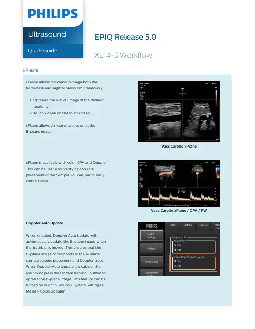
UltrasoundQuick GuidexPlanexPlane allows clinicians to image both the transverse and sagittal views simultaneously.1. Optimize the live 2D image of the desiredanatomy.2. Touch xPlane on the touchscreen.the trackball is moved. This ensures that theB-plane image corresponds to the A-planesample volume placement and Doppler trace.When Doppler Auto Update is disabled, the user must press the Update trackball button to update the B-plane image. This feature can be turned on or off in Setups > System Settings > Mode > Color/Doppler.vessel or structure.3. Touch 4D or 4D HV on the right side of the touchscreen.Tip: In 4D Half Volume the A-plane and B-plane MPR crosshair defaults to the center of the image area. Move the crosshair to the correct location.Vasc Carotid 4D Half Volumethe XL14-3 while in one of the 3D or 4D modes. 1. In 2D, confirm that the Scan Orient is set correctly for the transducer’s orientation to the vessel or structure. The Scan Orient can be set to either Long or Trans and is set by Scan Orient rotary on the right of the control panel.2. Select the preferred 3D or 4D scanning mode on the touchscreen.3. Touch the preferred AutoVue on the 3D tab.Tip : During an exam, the last AutoVue selected will be remembered when switching between 3D and 2D. For example, if the user had the short axis volume of the carotid selected and then returns to 2D to perform another acquisition, when the users enters 3D again, they will be returned to the short axis AutoView instead of the default long axis AutoVue.Vasc Carotid Vessel Cast with CPA4. T ouch 4D on the right side of thetouchscreen or press the Start trackballbutton.Vascular Tips• xPlane CPA is great for outlining vessel lumens.• When using a vascular TSP, the system defaults to the long axis AutoVue.• The 4D Half Volume mode can show half of a vessel in the orthogonal plane with a higher frame rate than standard 4D.This can be useful during procedures when visualizing balloon placement, for example.Please consult the user manual for further information.© 2019 Koninklijke Philips N.V. All rights are reserved. Philips reserves the right to make changes in specifications and/or to discontinue any product at any time without notice or obligation and will not be liable for any consequences resulting from the use of this publication. Trademarks are the property of Koninklijke Philips N.V. or their respective Printed in The Netherlands. 4522 991 48421 * MAY 2019。

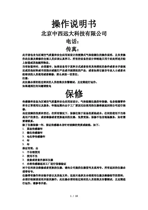
操作说明书北京中西远大科技有限公司电话:传真:此手册包含为区域空气质量和安全应用而设计的便携式气体检测仪的操作说明,且负责操作此仪器及维修的全部人员应该认真学习。
所有的设备的设计和制造只用于此处所述并贴上标签或其他随同物品。
当有标签和时,必须遵守。
如果设备用于某种方式或者没有具体授权的条件或者本手册规定或其他材料或书面指示或随行产品或书面授权的产品,或者如果它被非专业人士或者未经培训的人员使用或者维修,那么承担一切责任。
注意:此仪器必须有经过培训的人员校准及告警测试,且定期进行运作。
如果遇到任何问题请致电保修传感器和设备为区域空气质量和安全应用而设计。
气体检测仪提供年保修,包含检测零件和非正常使用以及服务。
年装运期内由于工厂原因无法使用的仪器将被返回到公司进行保修。
决定故障的性质和责任。
在所有情况下,保修仅限于设备的原始成本。
任何的使用不当将是用户的责任,或者维修或者更换退回的仪器,免费受保。
保修不包含现场服务,如有需要请联系。
除了仪器保修一年,保证传感器本身针对故障的变质或缺陷,如下:1.固态传感器年2.催化传感器年3.电化学传感器年4.年5.年保证有效,由1.不合理使用2.使用不当3.故意或者意外损坏仪器4.未将传感器返回工厂进行保修验证对于任何涉及维修或者更换的仪器,请向公司提供仪器型号及系列号。
所有返回的仪器必须带有号。
仪器带有操作和安装手册以及其他文件。
这些只是涉及合理使用仪器及维修细节的资料,必须仔细阅读说明并按其操作。
此仪器必须有经过培训的人员校准及告警测试,且定期进行运作。
请参考手册。
注意手册中的操作说明应有负责操作和维修此仪器的人员仔细阅读。
此仪器必须由培训过得人员进行校准和告警测试,每次使用之前检查功能。
用户必须认识并且明白气体检测的复合性,显然这种仪器是有价值的工具,客户必须了解此仪器的内在局限性。
不承担任何责任和由于使用仪器直接或间接造成的财产损失,或基于来自仪器数据的决策。

本手册提供如下介绍:*手动和电动(就地和远程)操作。
*执行器的准备和安装。
*根据有关阀门正确操作的要求,对执行器进行初级设定。
*根据现场具体控制和指示的要求,对执行器进行二级设定。
*维护-故障排除。
*销售和服务。
RotorkIQ系列执行器-全世界首家推出无需打开电气端盖即可进行调试和查询的阀门执行器。
使用所提供的红外线设定器进入执行器的设定程序,即使在危险区域,也可安全、快捷地对力矩值、限位以及其它所有控制和指示功能进行设定。
IQ的设定和调整在执行器主电源接通和断开时均可完成。
标准诊断功能可对控制系统、阀门和执行器的状态进行诊断,并通过执行器的显示屏上的图标和帮助屏幕来显示。
按一下设定器的按键即可在显示屏上对相应阀位的瞬时力矩进行监视。
内置的数据记录器可获取操作和阀门力矩数据,可提醒PC机的。
目录12保存3IQ3.1 手动操作3.2 电动操作3.33.444.1 IQ7至A和Z 4.2 IQ7至B4.3 IQ40至A和Z 4.4 IQ40至B 181919192021303061636871表如无意外,气元件。
调试IQ何电气箱盖。
箱盖而使执行Rotork每一台Rotork式:1.阀位-2.阀位-阀位指示灯供)器设定值而导断”。
(参见第●●●量等增大)将不显示。
(参见第23页3页)4.7是在执行有效(参见第4.7)都将显示,执行器大约104个螺栓固4.3 I Q40至A和Z 图8,将加,使定位螺栓与底5.1 提顶部安装a)体-执行器图19 转角箱的输入(或长形次的调节控至S450%。
保护跳断。
(详见出版物IQM(请参见第7、8)位置。
驱动器的下止手松开锁定螺(逆时(约等于1mm)。
有“上止档”线性驱动或同等的耐高脂。
线必须使用环型接,分清端子安装前应确保参见第10 P?PC Ir Cr使用距离名称1.*2.*3.4.5.,可看到窗口*5.6.7.8., 7.3按键+阀位。
用键可从(瞬间力矩+第44页第107.5新口令按键显示将变为口令。

福斯3200I Q说明书中文版-CAL-FENGHAI.-(YICAI)-Company One1Logix3200IQ智能定位器调试说明一、简介Logix3200IQ智能定位器接受4-20mA模拟量输入,4-20mA模拟量输出。
二、定位器操作面板介绍Logix3200IQ智能定位器就地操作面板由能够自动调校零点和满量程的QUICK-CAL快速调校按钮与可以手动操作定位器的两个点动按钮(↑和↓)以及八个DIP 开关和可以调节定位器增益的旋转开关组成。
三、定位器DIP开关的设置定位器运行之前,首先设置DIP开关,下面就每一个DIP开关的设置进行了说明1、作用方式作用方式分气开式(A TO)和气关式(A TC)两种,调试前根据阀门的类型进行设置。
2、阀门关闭的信号4mA 信号4mA时阀门处于全关位置,信号20mA时阀门处于全开位置20mA 信号20mA时阀门处于全关位置,信号4mA时阀门处于全开位置3、阀位与信号对应曲线线性曲线(Linear)阀门位置与信号成线性关系选择曲线(Optional)选择了这个按钮,就激活了下一个DIP开关4、可选择曲线%=阀位与信号成等百分比Custom 用户自定义曲线5、自动校准on 每次按动QUICK-CAL按钮,定位器就自动调整参数进行调试off 每次调试时,只能根据出厂前的预设置即调节定位器增益的旋转开关的位置进行调试无论哪一种情况,调节定位器增益的旋转开关都可以进行调节,调节完毕,不用重新进行调试,是即时生效的。
6、稳定性开关Low-Friction V alves 适用低摩擦力调节阀High-Friction V alves 适用高摩擦力调节阀7、备用开关8、定位器调试方式Auto 定位器自动调试Jog 手动调试,用户可以根据需要手动确定阀门的100%的位置二、手动点动调试首先将调校DIP开关拨到Jog位置,用户只能手动设置满量程,不能设置全关位,阀门全关位为默认状态。

1. 便携式气体检测仪2. 量程:0-3%(20、50、100、200、500、1000PPM或更高浓度%LEL选择,由业主确定)3. 最小分辨率:0.01 % (0.1、1.0PPM由厂家根据测定的范围而确定)4. 运行温度:-20-50℃5. 湿度:0-95% (无凝结水)6. 报警:内设报警装置(声、光)7. 显示:高清晰数字显示8. 取样方式:内置取样气泵9. 电力:8、或14小时的电池选择10. 充电器:外接充电器11. 尺寸(mm):181.1Х85.9Х101.612. 重量(Kg):1.1KG(包括电池)特性:电源:4C 碱性或镍镉电池碱性电池:24小时镍镉电池:12 小时标准可用气体:二氧化碳:2000PPM,1%体积百分数,10%体积百分数碳氢化合物:10,000PPM,100%LEL,100%体积甲烷氧气:25%体积百分数一氧化碳:1%体积百分数或更高对于所有气体要求有其它可用的量程其它可用气体:乙醛、丙酮、丙烯醛、苯、丁烷、环己胺、二乙基胺、二甲胺、乙烷、乙醇、乙烷基苯、乙撑氧、甲醛、氟里昂152、氟里昂134A、四氟甲烷、庚烷、甲醇、丙烷、苯乙烯、二甲苯等传感器:二氧化碳(CO2)和碳氢化合物(HCS):红外线传感器氧气(O2):长寿命电化学传感器指示器:低、高报警发光二极管指示,工作发光二极管指示,低电池发光二极管指示,泵发光二极管指示。
显示:3位显示控制:电源-开/关。
确认报警按钮。
泵-开/关。
3量程选择器开关。
报警:带有发光二极管指示的2 报警设定点(低报警和高报警)和声光报警。
采样方法:采样泵吸入。
低电量:连续的声音和发光二极管指示。
故障:连续的声音和(Active)发光二极管熄灭。
校准传感器包含两部分:零点标定和量程标定。
零点标定,首先开启采样泵,并用干净的大气通气约1分钟,然后用小螺丝刀通过旋转前面板上的按钮zero调整读数到0。
为了确保不在零点之下的水平,最好是最初的时候调到零之上,然后把读数降为零。

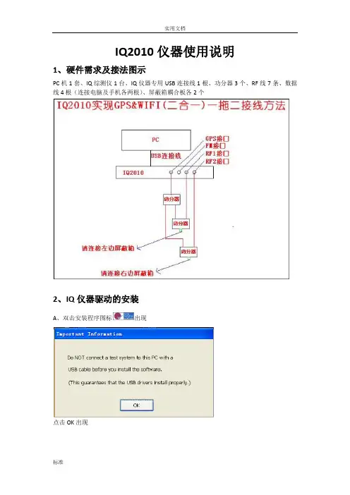
IQ2010仪器使用说明1、硬件需求及接法图示PC机1套、IQ综测仪1台、IQ仪器专用USB连接线1根、功分器3个、RF线7条、数据线4根(连接电脑及手机各两根)、屏蔽箱耦合板各2个2、IQ仪器驱动的安装A、双击安装程序图标出现点击OK出现勾选后三个选项如上所示,然后点击Install Selected ItemsOk 出现Install出现Next出现选Modify 然后Next出现Next 出现Install出现点击Finish然后等待4秒钟,自动出现下一个对话框如下Next出现选I accept the terms in the license agreement然后nextInstall选安装目录盘,一般选C盘然后okNextInstall点击Finish然后等待4秒钟,自动出现下一个对话框如下Next选I accept the terms in the license agreement然后nextNextInstall点击Finish完成IQ仪器驱动安装,此时桌面会多出一个快捷图标3、驱动安装验证在桌面图标我的电脑上右键管理打开设备管理器如下查看通用串行总线控制器会多出红框所示的两个驱动且无叹号显示,即表示驱动安装已安装完毕。
或者双击打开桌面快捷图标后出现鼠标单击红框选中地方connect tester出现鼠标单击红框显示地方Connect开始连接仪器如下红框选择地方显示表示成功关闭对话框后开始测试。
4、测试软件中IQ仪器配置说明智能平台中,IQ仪表配置与其他仪器配置主要不同是:综测仪控制类型及无线仪表类型:此处配置主要根据当前所使用仪器与电脑的连接方式,IQ2010主要是通过IQ专用USB连接线来连接的,根据机型要求此处选择LXI/LAN或者USB 两种,配置下端口其他不需配置。
IQ200series multi-function harmonic component meter user manualA.Function,technical parameter1、Function1)、Measurement of three-phase voltage,current,active power,reactive power,apparent power,Four quadrant power,power factor,frequency,maximum power2)、Measurement of3-63sub harmonic of each phase voltage,current harmonic content and total content3)、1active energy pulse output,1reactive energy pulse output 4)、Maximum Demand(U,I,P,Q,S)5)、6DI,2DO(relay output),2Analog Output4-20mA6)、1RS485,MODBUS-RTU,LCD display2、Technical Data B,Programming and operating1、Display:three-phasevoltagefrequencythree-phasecurrentPower factorThree-phaseactive powerPsumThree phasereactive powerQs(Figure1)(Figure2)(Figure3)(Figure4)Three phaseapparent powersumThree phasepower factorTotal powerfactoractive energy(forward/backforward)reactive energy(forward/backforward)(Figure5)(Figure6)(Figure7)(Figure8)Total harmoniccontent ofvoltage3-63secondharmoniccontentTotal currentharmoniccontent3-63secondharmoniccontentThe MaximumDeamandandThe CurrentDemand6input state2output state(Figure12)Note1(Figure11)Note2(Figure10)Note3(Figure9)Explain:1)Figure1-Figure10shows the interface of common data display instrument,according to the""or""button switch interface.2)According to the""button in the common data interface,enter the phasevoltage harmonic data display interface such as(Figure12).3)According to the""button in the common data interface,enter the datadisplay interface such as phase current harmonics(Figure11).4)In the harmonic data display interface,press"MENU"key,can return to thecommonly used data display interface.Note1:according to the""key A/B/C phase voltage harmonic distortiondata display interface switchingAccording to the""or""can choose to display the time harmoniccontent(3-63).Note2:according to the""key A/B/C phase current harmonic distortion datadisplay interface switchingAccording to the""or""can choose to display the time harmoniccontent(3-63).Note3:at this screen,you can press the"MENU"key to see the otherDemand Values(I-current,P-total active power,Q-total reactivepower,S-total apparent power)2.Setting up:Press"MENU".""."".""."".""to finish setting up.MENU:press this button to enter into the programming mode when inMeter measurement display,displaying‘password’on the meter.Programand set up the meter only after entering the correct password,instrumentfactory initial password0001;the other function of the“MENU”button is to backspace during theprogramming process.Press“”and“”to choose the parameter for modification select thenumber in each digit(in XXXX form).“”and“”key:select the parameters or to increase or decrease thecursor position data""key parameters:enter the next layer of menus or save theModified value and returns a layer on the menu.The organizational structure of the menu is as follows:Users can choosethe appropriate programming setting parameters according to the actualsituation.Featrue DataWiring3-phase3-wire,3-phase4-Wire Citification GB/T 22264.1-2008 (China)Input voltage AC380V(100%-120%)Continuous Input Current0~5A Continuous:20Ie/1s Voltage Operation AC220V(85~265V)Active power pulse output5000imp/kwhReactive power pulse output5000imp/kvarhDigital Input Passive contact inputDigital Output Relay output AC220V5A Communication interface RS-485、MODBUS-RTU Accuracy0.2classDisplay LCDFrequency40~60Hz,0.1HzConsumption≤5VAEnvironment -10~55℃without corrosive gas (at20℃RH≤90%,at40℃RH≤50%)Dimensions96×96×75(L*W*D)Level1Level2Level3DescriptionPasswordInput passwordDefaultpassword0001Enter into programmingonly when the enteredpassword is correctSystemsetupChangePassword0-9999Reset passwordEnergyclearance YES/NOElectric energy is clearedto zero after confirmation backlighttime0-9999Unit:second.Default value:120NetWorksetupConnectionmodeN.3.4N.3.3Default value:N.3.4Voltagetransformingratio1-9999Set up voltage signal atio=Primary alue/secondaryvalueCurrenttransformingratio1-9999Set up current signal ratio=Primary alue/secondaryvalueComm.setupComm.rate BAUD4800,960019200Default:9600Communication data type N.8.1N.8.1:nonecannot changeAddress1-247Meter addressrange:1-247AlarmsetupUaMax0-9999(V)Set A/B/C phase alarmvoltage valueThe default setting of0,touse the alarm functionUbMax0-9999(V)UcMax0-9999(V)Analog1/2outputsetupEnable ON/OFF Turn on or turn off theAnalog outputItem Ua/Ia/Ps……Set Part-E to get more info Up Limit0-7500Set Part-E to get more infoDemandsetupEnable ON/OFF Turn on or turn off thisfunctionTime15(min)Demand Periodcannot changeClear YES/NO Clear the DemandDC220V±15%Page.01Page.02Page.03Page.04Page.05Page.06C.Mounting and wiring1.Mounting dimensions:2.Mounting method:Installed in a dark way installed on the panel 2.Terminalwiring:Note:L-N is the auxiliary power supply.Make proper wiring according to themeter enclosure wiring diagram!1)Auxiliary power supply:The IQ200series multi-functional power meter has universal AC/DC switch power supply input interface,offering standard products with the 220V AC/DC or 110V AC/DC power supply interface when not stated specially.The meter’s operating power supply voltage limit is 85to 265V (AC/DC).Make sure that the supplied power supply is suitable for this series product,to avoid damages to the product.A).For AC power supply,it is recommended to install a 1A fuse on thelive-wire side.B).In regions of worse power quality,it is recommended to install a surgeprotector in the power supply circuit to avoid lightning,and install a fast pulse burst suppressor.2)Input signal:The IQ200series product uses the calculation method of individual collection in each measurement channel,ensuring consistency and symmetry when in use,suitable for different load types.Remark:A)Voltage input:the input voltage should not exceed the product’srated input voltage (100V or 400V).Otherwise,a PT should be considered to use,and a 1A fuse must be installed in the voltage input end.B)Current input:the standard rated input current is 5A.An externalCT should be used for above 5A current.If the used CT is connected to other meters,serial connection should be made.Make sure to disconnect the CT’s primary circuit or short circuit the secondary circuit before removing the product’s current input wiring.A connection bar is recommended to use.Do not directly connect to the CT,convenient for removal.C)Make sure that the input voltage and current are corresponding,with consistent phase sequence and direction;otherwise,value and symbol errors (power and energy)will occur!D)The meter input network is configured to the CT quantity in thesystem.Choose the 3-phase 3-wire 2-compnent method for 2-CT cases,while the 3-phase 4-wire 3-component method is chosen for 3-CT cases.The input net setup in the meter wiring and meter programming should be consistent with the wiring methods for the measured loads.Otherwise,this will result in incorrect voltage or power measurements by the meter.In a 3-phase 3-wire system,the voltage measurement and displayed value are related to line to line voltage,while in a 3-phae 4-wire system,the voltage measurement and displayed value are phase to phase voltage.3)communication port:41for the RS485(A+),42for the RS485(B-),43for the shieldeThe communication line adopts ZR-RVSP 2×1.5mm2two core shielded twisted pairThere must be a shield must be tightly twisted 4)electric energy pulse output:31-active power pulse output (-)32-active power pulse output (+)33-reactive power pulse output (-)34-reactive power pulse output (+)5)2 way relay output (4-7):4-5 for a set of ,6-7 for a set of .Normally open passive contact signal output,the contact capacity of 5A AC220V (resistive load) (the relay controlled by the communication command)6)digital input (60-66):6sets of passive contact input,60for the COM (common)7)analog output (50-52):2analog output,50is the common GND for the analog.the maximum load 400Ω,the output current 4-20mA.see the Part-E to get the output items info.this feature is optional.D.Digital communication The serial asynchronous half-duplex RS485communication interface is offered,using MOD-BUS-RTU protocol.E.Analog Output ItemsThe following items are the secondary side of the electrical parameters that IQ200mesaured.Eaton corporationAsia Pacific Headquarterne 280,Linhong Road Changning District Shanghai 200335Tel:86-21-52000099Eaton is a registered trademark of Fax:86-21-52000200Eaton Corporation All trademarks are property of their respective owners © 2018 Eaton Corporation All Rights Reserved Printed in China APr -20188) screw reated tightening torque 5.1kgf.cm (0.5N.m)。
Manual del mejor uso de tu lavadora.Como mejor funcionan tus electrodomésticoses usándolos entre toda la familia. QuickDrive TM2 M a n u a l d e l m e j o r u s o d e t u l a v a d o r a3Manual del m ejor uso de t u lavadoraPONER LA LAVADORA Y CUALQUIER TAREA DOMÉSTICA ES COSA DEHOMBRES Y DE MUJERES, POR IGUAL.Si nunca has puesto una, hoy es un gran día para comenzar.TM .Nadie nace sabiendo cómo funciona una lavadora. Sigue estos pasos para familiarizarte con ella.4 M a n u a l d e l m e j o r u s o d e t u l a v a d o r a5Manual del m ejor uso de t u lavadoraTe lanzamos algunas ideas para que, además de poner la lavadora, empieces a repartir cualquier tarea de casa como hay que hacerlo: EN EQUIPO.“AYUDAR” NO VALE.Las tareas domésticas sonresponsabilidad de todos, por lo tanto no vale con “ayudar”. Mejor hazlas.12TOMA LA INICIATIVA.No esperes a que tu pareja te diga qué hacer. Nadie debería encargarse de dirigir y coordinar las tareas domésticas. ¿El cesto está lleno? ¡Pon la lavadora! ¿Se acerca la hora de cenar? ¡Seguro que sabes lo que toca!3REPLANTEA EL REPARTOSi el peso de “poner la lavadora” o de cualquiertarea crea conflictos o algún miembro de la familia considera que el reparto no es justo, habrá que dialogar y pensar nuevas estrategias.4DIALOGA POR UN REPARTO JUSTOPara que todos los miembros asuman su responsabilidades importante que haya una negociación en la queparticipen todas las partes implicadas. Que uno solo sea quien tome la decisión no suele dar buen resultado. Y si no os ponéis de acuerdo, entra en y usa nuestro configurador de tareas5ASIGNA TAREAS POR GUSTOSSi a ti no te importa poner la lavadora y a tu pareja le supone un drama, adjudícate esa tarea. Si vais compensando gustos será más fácil ponerse en marcha.6EQUILIBRA LOS HORARIOSEl equilibrio es importante: Si pasas 8 horas en la oficina y tu pareja 4, hay que tenerlo en cuenta ¡Un inciso! Trabajar desde casa, cuidar a los hijos o a una persona mayor también es trabajar. La excusa de: “pero si estás en casa” no cuela.7MISMOS DESCANSOSPara que el reparto de tareas sea más justo lo suyo es que el reparto del tiempo de descanso también lo sea. Mientras uno hace la cena, que el otro bañe a los niños, mientras uno pone la lavadora, que el otro recoja la mesa... Si todos colaboráis, podréis disfrutar antes de una peli juntos.8REVISA EL PLANSi pasado un tiempo el reparto ha dejado de funcionar, tendréis que repensarlo de nuevo. Es mejor renegociarlo cuando haga falta, que perder tiempo y energía todos los días debatiendo a quién le toca poner la lavadora.6M a n u a l d e l m e j o r u s o d e t u l a v a d o r a7Manual del m ejor uso de t u lavadorade Psicología Clínica y especializado en crianza y asesoramiento a padres.“Las tareas del hogar no son del hombre ni de la mujer, tampoco de los padres. Todos los que vivimos bajo el mismo techo compartimos la responsabilidad de las tareas de casa, y hay que repartirlas de forma corresponsable: nadie tiene que “ayudar” a poner la lavadora o a hacer la cena, son cosas que hay que hacer y alguien tiene que hacerlas. Los miembros de la pareja se pueden ayudar con tareas del trabajo o con cosas externas a la casa, pero si hablamos de cocinar la cena o lavar la ropa, aquí nadie ayuda a nadie porque es cosa de todos. Como todos tenemos que comer, y a todos nos gusta llevar la ropa limpia, todos tendremos que remangarnos y ponernos manos a la obra. Si todos colaboramos es más fácil que todos estemos a gusto en casa.”1ENSÉÑALESParece obvio pero antes de realizar cualquier tarea, debes enseñarles cómo hacerlo: baja a su nivel, usa un lenguaje sencillo y ve paso a paso ¡Para ti puede ser fácil, pero para ellos no tiene por qué serlo!2CADA TAREA A SU TIEMPOAdáptate a su edad. Por ejemplo, con dos años pueden llevar la ropa sucia al cesto; con tres o cuatro pueden poner y quitar la mesa, con cinco o seis cocinar algo sencillo (¡con tu ayuda!), y con ocho o nueve años pueden quitar el polvo, poner la lavadora o el lavaplatos.*3DEJA QUE FALLEN¡Permíteles cometer errores! Si quieres queaprendan, les tendrás que dejar meter la pata ¿Cómo si no van a aprender!4DA EJEMPLORecuerda que eres su modelo. Para cada niñolo normal es lo que ha visto siempre en casa. Ayúdale a crecer sin pensar que las tareas de casa son cosa de papá o de mamá.LAS TAREAS DOMÉSTICAS TAMBIÉN SON COSA DE NIÑOS.Para implicarles en ellas debéis tener en cuenta esto.* Afirmación avalada por el psicólogo Alberto Soler#YaNoHay ExcusasUna iniciativa de Lavadoras Samsung QuickDrive TMPoner la lavadora y cualquier tarea domésticaes cosa de hombres y de mujeres por igual.Reparte equitativamente y contribuye a crearuna sociedad más justa.https:///es/quickdrive/yanohayexcusas/。
iq智慧床垫使用说明书
IQ智慧床垫使用说明书如下:
1.使用前,请将床垫打开并展开。
2.将床垫放置在床架上,确保床垫平稳。
3.将床垫与电源连接。
请注意,电源必须符合国家安全标准。
4.按照说明连接WiFi并下载IQ智慧床垫的App。
5.打开App后,按照说明进行注册并绑定您的床垫。
6.按照说明设置您的偏好和个人信息。
7.开始享受智慧床垫带来的舒适体验。
8.如果需要清洁,请使用干布轻轻擦拭。
9.如果需要维修或更换部件,请联系官方售后服务。
注意事项:
1.请勿把床垫插到不正常的电源插头或不符合国家安全标准的电源。
2.请勿将床垫弄湿。
3.请勿在床垫上跳跃或剧烈运动。
4.请勿在床垫上放置油性或腐蚀性物品。
5.请勿在床垫上吸烟或使用火源。
希望这份说明书对您有所帮助。
如有任何疑问或问题,请随时联系官方售后服务。
iqt250说明书
IQT罗托克电动执行器IQT250:角行程智能型电动执行机构(又称为阀门电动装置、阀门电装、阀门电动头),输出扭矩500N。
m,智能一体化产品,模拟量控制,输入输出4~20mA,电压380VAC,防护等级IP67。
IQT罗托克电动执行器IQT500广泛应用于电力、石油、钢铁、化工、食品、轻工、医药、输油管道、污水处理,特别是自动控制系统中,即可满足频繁调节控制,又能满足断续控制的要求。
IQ系列执行机构*市以来,是阀门市场中一款“智能型”非侵入式执行机构产品。
该型号引进了一系列全新的功能,包括执行机构操作历史数据记录,并且用红外设定工具取代了传动的机械设置方式。
IT角行程执行机构自上市以来,这款直接驱动角行程执行机构产品完全拥有IQ的全部智能功能。
IQ100X Series User ManualA, Catalogue Number Data2, Function1), V I KW Kvar, reactive power, apparent power, four-quadrant energy, power factor, frequency,2), 1 active energy pulse output, 1 reactive energy pulse output3), 1 AO:4-20mA4), 1 RS485,MODBUS RTU5), 6 DI,2 DO(relay output)6), LCD displayB, Programming and operating1, Display:VVV3-phase KWH Power factor FrequencyPFPress ▲ and ▼ to change the parameters。
Set DIS-DIS.P-AUTO to change display automatically2.Setting up:Press “MENU”, “▲”, “▼”, “►”, “◄”, “” to finish settingup.MENU:press this button to enter into the programming mode when in metermeasurement display, displaying ‘PROC’ on the meter. Press “”, anddisplay “code”. Program and set up the meter only after entering the correctpassword (default value: 0001); the other function of the “MENU” button is tobackspace during the programming process. Press “►” and “◄” to choosetheparameter for modification and to select the number in each digit (inXXXX form). “▲”and “▼”is to increase and decrease values, while the“” key is used to confirm the modified parameter.The organizational structure of the menu is shown as below. Users canselect proper programming setup parameters according to their actualsituations.The diagram below is the programming menu structure. Press the MENU keyto enter into the following programming operations.- 2 -C. Mounting and wiring1. Mounting dimensions:2. Mounting method:1)Choose a proper position on the fixed switchboard to cut out a mounting hole as per the cutout dimension.2)Remove the meter, and loosen the locating clip.3)Mount and insert the meter into the meter hole of the switchboard. 4)Insert the meter ’s locating clip.3. Terminal wiring:Note: L-N is the auxiliary power supply. Make proper wiring according to the meter enclosure wiring diagram!1)Auxiliary power supply: The IQC series multi-functional power meter has universal AC/DC switch power supply input interface, offering standard products with the 220V AC/DC or 110V AC/DC power supply interface when not stated specially. The meter ’s operating power supply voltage limit is 85 to 265V (AC/DC). Make sure that the supplied power supply is suitable for this series product, to avoid damages to the product.A). For AC power supply, it is recommended to install a 1A fuse on thelive-wire side.B). In regions of worse power quality, it is recommended to install asurge protector in the power supply circuit to avoid lightning, and install a fast pulse burst suppressor.2) Input signal: this series product uses the calculation method of individual collection in each measurement channel, ensuringconsistency and symmetry when in use, suitable for different load types. Remark:A) Voltage input: the input voltage should not exceed the product ’srated input voltage (100V or 400V). Otherwise, a PT should be considered to use, and a 1A fuse must be installed in the voltage input end.B) Current input: the standard rated input current is 5A. Anexternal CT should be used for above 5A current. If the used CT is connected to other meters, serial connection should be made. Make sure to disconnect the CT ’s primary circuit or short circuit the secondary circuit before removing the product ’s current input wiring. A connection bar is recommended to use. Do not directly connect to the CT, convenient for removal.C) Make sure that the input voltage and current are corresponding,with consistent phase sequence and direction; otherwise, value and symbol errors (power and energy) will occur!D) The meter input network is configured to the CT quantity in thesystem. Choose the 3-phase 3-wire 2-compnent method for 2-CT cases, while the 3-phase 4-wire 3-component method is chosen for 3-CT cases. The input net setup in the meter wiring and meter programming should be consistent with the wiring methods for the measured loads. Otherwise, this will result in incorrect voltage or power measurements by the meter. In a 3-phase 3-wire system, the voltage measurement and displayed value are related to line to line voltage, while in a 3-phae 4-wire system, the voltage measurement and displayed value are phase to phase voltage.D. Digital communicationThe serial asynchronous half-duplex RS485 communication interface is offered, using MOD-BUS-RTU protocol.。