SINER-ROTORK 说明书
- 格式:pdf
- 大小:1.06 MB
- 文档页数:77

泰勒螺柱焊接系统有限公司SIK2-H电容放电式全自动螺柱焊枪操作说明书GUIDE VERSION 2L目录页码内容3 总则5 简介6 总体布局7 焊接步骤8 安全11 焊枪分解图及零部件列表 22 设备调节24 焊接速度25 跟换螺柱直径27 更换夹头28 夹头类型30 螺柱进料软管31 更换推杆32 推杆类型32 顶端传感器33 焊接质量34 故障诊断38 EC合格证制造厂家英国泰勒螺柱焊接系统有限公司地址:COMMERCIAL ROADDEWSBURYWEST YORKSHIREWF13 2BDENGLAND电话: +44 (0)1924 452123传真: +44 (0)1924 430059邮箱: ***************************技术支持电话: +44 (0)1924 487703销售电话: +44 (0)1924 487701说明书用途本说明书适用于 :☞焊接系统设备操作用.☞本焊接系统终端客户安装、操作人员用。
本说明书提供以下技术指导 :☞安装及联接☞系统操作☞技术参数☞零部件☞附件更详尽信息如需更详尽资料请直接联系我们(详见第1页)或致电当地技术支持(可致电我司查询分销商及代理商联系方式)本说明书包含一些重要信息,是操作者安全使用本焊接系统的必备品。
系统操作人员必须要完全掌握本说明书的使用方法。
为安全起见,本说明书应放置于操作人员随时可取之处。
系统销售或转让时必须随机配备本说明书,并请立即告知我司购机者地址、姓名以便我司能及时联系确保设备安全。
系统安装前请仔细阅读本说明书。
请严格遵守安全操作指导。
简介设备说明电容放电式螺柱焊接设备结构轻盈、便于携带,特别适合于较小直径的螺柱焊接,可将碳钢及不锈钢螺柱在较薄的金属板、抛光或预涂材料的工件上进行焊接,绝大多数情况下几乎不留焊接痕迹。
该设备由一台控制电源,一把全自动焊枪,以及一些必备的焊接电缆组成。
工艺电容放电式螺柱焊接是一种利用电容放电产生的能量进行焊接的一种焊接工艺。
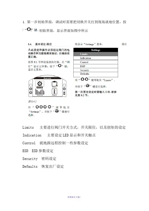
1. 第一步初始界面,调试时需要把切换开关打到现场就地位置,按初始界面,显示界面如图中所示Limits 主要进行阀门开关方式,开关限位,以及扭矩的设定Indication 主要设定LED显示和开关触点Control 就地跟远程控制一些参数设定ESD ESD参数设定Security 密码设定Defaults 恢复出厂设定2.阀位设定,选择图中Limits,按进入关限位调试界面,Direction 开关方向,默认ClockActiom 开关方式 Limit 限位 Torque 力矩Torque 开关阀力矩值的设定Set Limit 设定开关限位进入该界面后,按选择菜单,Direction 默认Clock,按下“”键以选择“ Close Settings”(关设定)中“Direction”方向)功能。
用或进行选择。
按下键进行确认。
Action 选项选择Limit按下“”键以选择界面,用或进行选择,按下键进行确认。
Torque 力矩值选择60%左右,这个跟阀门实际需要的扭矩为准,按下“”键以选择界面,用或进行增减,按下键进行确认。
Set Limit首先将电动头涡轮箱出的2个限位螺栓松出,按下遥控器“”键以选择界面,首先设定阀门关限位将执行器和阀门动作至全关位置后(可以手轮顺时针转动,手轮上有指示),手轮在往开方向回半圈到一圈,然后电动头涡轮箱上面的螺栓(靠近电动头)往里面拧,直到顶住后往外退出1-2圈,锁紧螺母,按下键进行确认关阀限位。
设定阀门开限位:将执行器和阀门动作至全开位置后(可以手轮逆时针转动,手轮上有指示),手轮在往关方向回半圈到一圈,然后电动头涡轮箱下面的螺栓(底部的)往里面拧,直到顶住后往外退出1-2圈,锁紧螺母,按下键进行确认开阀限位。
3.Indication主要设定LED显示和开关触点开关触点按下“”键以选择界面,用或进行增减,按下键进行确认。
LED 显示4.Control 就地跟远程控制一些参数设定就地参数设定 Maintained 保持远程控制参数设定5.Security 密码设定6.Defaults 恢复出厂设定(注:可编辑下载,若有不当之处,请指正,谢谢!)。

PLEASE READ THIS GUIDE CAREFULLY BEFORE INSTALLING OR OPERATING THE CONTROLLER.PLEASE OBSERVE CAREFULLY ALL SAFETY PROCEDURES/INSTRUCTIONS.DUE TO THE POWER REQUIREMENTS AND ELECTROMAGNETIC EMISSIONS PRODUCED DURING NORMAL USE, THIS MACHINE MUST ONLY BE OPERATED IN AN INDUSTRIAL ENVIRONMENT.THIS MACHINE OPERATES FROM A MAINS SUPPLY OF 380/415V AC @ 50/60 HzNEVER REMOVE ANY PORTION OF THE UNIT HOUSING WITHOUT FIRST ISOLATING THE CONTROLLER FROM THE MAINS ELECTRICAL SUPPLY.NEVER OBSTRUCT THE UNDERSIDE, FRONT OR REAR PANELS AS THIS MAY CAUSE THE UNIT TO OVERHEAT DURING OPERATION.DO NOT USE THIS WELDING POWER SOURCE FOR PIPE THAWING.THIS EQUIPMENT HAS BEEN EMC TESTED AND APPROVED IN ACCORDANCE WITH BS EN 60974‐10 (CATEGORY 2).本设备已按照安装设备前,请仔细阅读本说明书。
请严格遵守本安全操作说明书。
由于电力要求及电磁辐射的缘故,本设备必须在工业环境中使用。
本设备电压为未切断电源前,不得拆解外壳任一部件。

OIL-INJECTED ROTARY SCREW COMPRESSORSG 2-5/G 7-11/G 15-22/G 30-45/G 55-75 (2-75 kW / 3-100 hp)ATLAS COPCO WORLDWIDEAtlas Copco, based in Stockholm, Sweden and founded in 1873, is an industrial groupwith a world-leading position in compressors, construction and mining equipment, power tools and assembly systems. Atlas Copco provides optimized compressed air solutions through sustainable productivity.NEW G SERIES: SCREW COMPRESSORS BUILT TO LASTAtlas Copco compressors have always set the standard for reliability and performance in the compressed air industry. With the new G 2-5, G 7-22, G 30-45 and G 55-75, Atlas Copco brings the power and durability of an industrial screw compressor to any type of small or medium sized industry.Built-in reliability• Rugged screw compressor technology fora 100% continuous duty cycle.• Up to 46°C ambient temperature conditions thanksto the selection of robust components.• Electro pneumatically operated inlet valvefor stable running and a long life time.Easy installation• Wireless concept.• Multiple variants (floor and tank mounted, with or without integrated dryer) for full flexibility.• Minimum footprint and cooling air discharge from the top allows placement against the wall or in a corner.Simple & quick maintenance• Patented cooler for easy cleaning and maintenance.• Grouped service points accessible throughthe removable panel.• Spin-on oil separator and filter.Integrated quality air solutions• The integrated dryer avoids condensation and corrosion in thenetwork. Optional filters for air quality up to class 1 level (<0.01 ppm).• Standard included water-separator.• Additional energy savings with the dryer’s no-loss mechanic drain.4Easy installation• A true plug-and-play solution, ideal machine for installation companies and OEMs. • Easy transportation by forklift. • Remarkably compact footprint.5Robust element & motor• The G’s compression element, the most used in its size. • 2-3% higher efficiency with V-belt compared to other belt-driven systems on the G 2-22.• Gear-driven drive train on G 30-75 for unequaled reliability and limited maintenance.1Advanced monitoring•State-of-the-art monitoring using a simple Ethernet connection.•Service and warning indications, error detection and compressor shut-down.•Optional Elektronikon ® graphic controller for further enhanced remote monitoring features and service time indications.2High tech oil vessel•Protection from oil contamination: extremely low oil carry-over thanks to the vertical design of the oil vessel.•Extremely low losses of compressed air during load/unload cycle thanks to minimized oil vessel size.3LWH- :Not availableLWH LWH • : OptionalTAILORED TO YOUR NEEDSSome applications may need or may benefit from additional options and more refined control and air treatment systems. T o meet these needs, Atlas Copco has developed options and easily integrated compatible equipment providing the lowest cost compressed air.TECHNICAL SPECIFICATIONSG 2-5/G 7-11/G 15-22/G 30-45/G 55-75 – 50 HzTECHNICAL SPECIFICATIONSG 2-5/G 7-11/G 15-22/G 30-45/G 55-75 – 60 HzNA: Not available.* Unit performance measured according to ISO 1217, Annex C, latest edition.** Mean sound level according to ISO2151, tolerance 3 dB(A).NA: Not available.* Unit performance measured according to ISO 1217, Annex C, latest edition.** Mean sound level according to ISO2151, tolerance 3 dB(A).Pack Floor G 7-75WH LPack Tank G 2-22FF Tank G 2-222935 0813 42 © 2016, A t l a s C o p c o A i r p o w e r N V , B e l g i u m . A l l r i g h t s r e s COMMITTED TO SUSTAINABLE PRODUCTIVITYWe stand by our responsibilities towards our customers, towards the environment and the people around us. We make performance stand the test of time. T his is what we call – Sustainable Productivity.。
FLW型旋涡流量计使用说明FLW型旋涡流量计是根据卡门旋涡原理制造用于测量封闭管道中液体、气体、蒸汽流量的精密仪表,由于检测元件密封在检测体内,不接触被测介质,且内部无可动部件,无需进行现场维护,因此深受广大用户的推崇,被广泛应用于石油、化工、冶金制药、热电、造纸工业等行业的计量管理及过程控制。
一、产品特点及主要技术参数●结构简单,内部无可动部件●检测元件不接触被检测介质●性能稳定、使用寿命长●同一传感器可测液体、气体、蒸气●在规定的雷诺数内,仪表系数不受流体的温度、压力、粘度及成分变化的影响。
●该仪表适用于雷诺数范围:2X10⁴-7X10⁶(DN25-DNl00)4X10⁴-7X10⁶(DNl50--DN300●产品普通型可实现瞬时、累计显示●温度压力补偿型可自动计算显示标准流量和工况流量,温度和压力等参数●蒸汽温度压力补偿型可自己计算显示质量流量,温度、压力、密度等参数●工作压力:1.6~4.0MPa●介质温度:—40℃~+200(一体型) —40℃~+300(分离型)●供电电源:自供电3.6VDC;需要远传可外接DC24V实现流量变送输出●环境温度:-25℃~+60℃●相对湿度:5%~95%●大气压力:86~106KPa●被测流体种类:液体、气体、蒸汽●准确度:1级、1.5级●输出信号:模拟输出:(全隔离二线制4—20mA) 远传距离1000m脉冲输出:(全隔离三线制VH一3V) 远传距离500m485输出:(全隔离485输出modbus协议,可以和PLC、计算机组态软件直接连接,无需自己编写驱动,可带256个负载) 远传距离1200m无线输出:(全隔离无线输出modbus协议,可以和PLC、计算机组态软件直接连接,无需自己编写驱动,可带256个负载)远传距离4500m●防爆等级:ExdIIBT4二、工作原理当在流体中插入一个流动方向垂直的非流线型柱体(旋涡发生体),在其下游侧会交替地产生二列内旋的旋涡列,称之为“卡门涡列”。

美国施乐辉关节镜体说明书生产者名称:美国施乐辉公司关节镜制作材料:镜身为医用不锈钢,镜头为蓝宝石镜头,中间为柱状晶体。
使用范围:在膝关节,肩关节,髋关节,肘关节等关节的关节镜手术中使用。
产品性能:分辨率≥7.43LP/mm(L=20mm)3622型关节镜体:口径:外径4mm视向角:30°视场角:115°工作长度:160mm3623型关节镜体:口径:外径4mm视向角:70°视场角:115°工作长度:160mm关节镜体清洗1. 把镜子浸泡在含酶的中性溶液中。
2. 用刷子擦净所有缝隙中看得见得残留碎屑,注意不要刮伤任何光学表面。
3. 用含酶的中性的清洗液的网垫擦净光学表面。
4. 然后用温水冲洗。
5. 光学表面用含异丙醇的网垫擦净。
然后用蒸馏水漂洗。
6. 或者用含丙酮的网垫擦洗光学表面。
然后用蒸馏水漂洗。
关节镜体的消毒方法方法:100% 环氧乙烷温度:131 +/-5华氏度(等于55摄氏度+/-3度)湿度:35-70%用量:736 mg/l时间:60 分钟服务哲学仅由Smith & Nephew授权的服务中心提供修理和调整服务如果需要服务,在退还仪器之前,联系您的经Smith & Nephew授权的客户服务代理人,向他询问您的返还授权号(RA),而且授权代理人也可以解释可行的归还服务和维修的程序。
需要服务的项目必须仔细包装好,以邮寄的方式(邮资已付)归还给Smith & Nephew,您的授权代理人会给您提供另外的指导。
注: 如果归还的产品已经由未授权的第三方维修车间和/或用未经Smith & Nephew公司同意的消毒方法消毒和/或和其他的机械设施接触后损伤,可能会额外收取成本费,不管是否出现在保修期内。
施乐辉关节镜手动器械说明书生产者名称:美国施乐辉公司手动器械制作材料:医用精钢制造。
手动器械名称及产品性能:滑杆结构,所配备的手动器械全部为不可拆卸无销钉设计。
'AWT' 系列出版物编号 E320C 发行日期 10/02控制与监控设备目 录基本的电相关性能 4转矩限位开关机构 5附加说明 6SyncroSET 说明 7SyncroSET 基本接线图 8SyncroSET 选项和编号 9SyncroPAK 说明 10SyncroPAK 选项 11SyncroPAK 基本配线图 12SyncroPAK 选项和编号 13SyncroPAK 远程控制电路 14在执行机构技术领域居领先地位拥有长达40余年在各种环境下的安装经验,Rotork已经发展出可靠性极强的设计理念。
今天,Rotork的执行机构在工艺领域中阀门操作和使用安全方面居于领先地位。
电动执行机构为集中控制阀门、水闸和风门挡板提供了手段。
作为工艺流程中的一部分或是在紧急情况,在有可能对环境和生命有害或有损害时,确保阀门使用的可靠性是最重要的。
执行机构是阀门、电源和控制装置3个要素的交汇点。
每个要素都有各自独特的设计要求,AWT执行机构以其完善的设计将三者结合在一起。
通过设计、研发和生产,对执行机构的测试已达到最高水平。
设计寿命、环境、振动和电气方面的测试都已实施。
每一个成品都经过一系列检测设备的测试,包括转矩、电力和机械操作以及用户控制指示平台的测试。
ROTORK 执行机构Rotork Controls Ltd, Bath, UKRotork Controls Inc, Rochester, USAAWT能够在两种基本的电形式下使用,即电机控制一体式或分体式:电机控制分体式--AWT SyncroSET电机控制分体式--AWT SyncroSET由3相发动机、减速箱以及包括可分驱动部件、限位及转矩开关和接线箱的阀门附件等部分组成。
SyncroSET执行机构必须在用户安装,连接可反向的接触器的情况下使用。
电机控制一体式--AWT SyncroPAK包括3相电机、可就地或远方控制的内置一体式启动接触器、减速箱、阀门附件--可分驱动部件、限位及转矩开关、分离式接线箱。

温度湿度气体2015价格表德国标准 东方精神壓力照度及位移思默康自动化设备(上海)有限公司价格生效期始于2014年10月15日1.0版TRW1-Series (T)TRW2-Series (T)0…10V / 4…20mANTC / PT / NiTPS1-Series (T)0…10V / 4…20mANTC / PT / NiTOW1-Series (T)TOW2-Series (T)TDE1-Series (T_av)TDE2-Series (T_av)风管温度防凍开关TDE2-Series (T_fp)通用温度有源传感器TUU1-Series (T)0…10V / 4…20mA通用温度无源传感器TUU2-Series (T)HPS2-Series (H_cs) HPS2-Series (H_lg)GDI1-Series (VOC)0…10V湿度:0..10V温度:0..10V可选 NTC ; PT ; NiPDE1- Series (dP_r) PDI1- Series (V&T) PDE2- Series (dP) PPE1- Series ( PPE2- Series (LRC1-Series(L)10V / 4…20mA CRC8-series (L&M)照度:0...10V人体活动:ON/OFF MRW2-Series(M)asia pacific照度及位移传感器温度湿度气体壓力照度及位移价格生效期始于2014年10月15日价格表其他配件德国标准 东方精神asia pacific配件asia pacific安装套件思默康自動化設備(上海)有限公司上海市閔行區莘庄工業區春東路479號C-1廠房2樓電話: (+8621) 5176 0211傳真: (+8621) 5176 0213泰慕康传感器科技有限公司香港新界荃灣168德士古道德豐工業中心2座13/樓10-11室電話: (+852) 3468 8636傳真: (+852) 3621 0002网站: / 邮箱: info@ asia pacific声明该价格表中,对技术信息都进行了简化,并保持随时更新。

DSGN-fm-50366 rev. None Page 1 of 1Effective: July 1, 2008Label Stock:Dimensions:Color/Material/Finish:NOTE: This portion of the document should not appear on produced Labels or IFUs .Description/Type:Stryker Instruments(269) 323-7700(800) 253-3210Print Location:Suppliers/Services:Part Number:Rev.6inch (width)x 6inch BookletPrint CenterColor Graphics on White Background 20#Bond or EquivalentN/AN/AInstructions For Use6205-001-700DENGLISH (EN)2015-036205-001-700 Rev-D IntroductionThis Instructions For Use manual is the most comprehensive source of information for the safe and effective use of your product. This manual may be used by in-service trainers, physicians, nurses, surgical technologists, and biomedical equipment technicians. Keep and consult this reference manual during the life of the product.The following conventions are used in this manual:▪ A WARNING highlights a safety-related issue.ALWAYS comply with this information to preventpatient and/or healthcare staff injury.▪ A CAUTION highlights a product reliability issue.ALWAYS comply with this information to preventproduct damage.▪ A NOTE supplements and/or clarifies procedural information.For additional information, especially safety information, or in-service training, contact your Stryker sales representative or call Stryker customer service. Outside the US, contact your nearest Stryker subsidiary.Indications For UseThe Stryker System 6 Battery Powered Heavy Duty Dual Trigger Rotary Handpiece, when used witha variety of attachments, is intended for surgical procedures involving drilling, reaming, driving wire or pins, cutting bone and hard tissue. ContraindicationsNone known. User/Patient SafetyWARNINGS:▪Only trained and experienced healthcare professionals should use this equipment. Beforeusing any system component or any componentcompatible with this system, read and understand the instructions. Pay particular attention toWARNING information. Become familiar with thesystem components prior to use.▪The healthcare professional performing any procedure is responsible for determining theappropriateness of this equipment and thespecific technique used for each patient. Stryker, as a manufacturer, does not recommend surgical procedure or technique.▪Upon initial receipt and before each use, operate the equipment and inspect each component fordamage. DO NOT use any component if damage is apparent.▪Upon initial receipt and before each use, clean and sterilize the equipment as indicated. Seethe care instructions manual supplied with theequipment.▪Perform recommended maintenance as indicated.Only trained and experienced healthcareprofessionals should maintain this equipment. See the care instructions manual supplied with theequipment.▪ALWAYS operate the equipment within the specified environmental condition values. See the Specifications section.▪ALWAYS follow the recommended duty cycle to prevent the equipment from overheating. See the Specifications section and/or the instructions for use supplied with the attachment.▪DO NOT use this equipment in areas in which flammable anesthetics or flammable agents aremixed with air, oxygen, or nitrous oxide.▪Take special precautions regardingelectromagnetic compatibility (EMC) whenusing medical electrical equipment like thehandpiece. Install and place the handpiece intoservice according to the EMC information in thismanual. Portable and mobile RF communications equipment can affect the function of thehandpiece.AccessoriesWARNINGS:▪Use only Stryker-approved system components and accessories, unless otherwise specified.Using other accessories may result in increasedelectromagnetic emissions or decreasedelectromagnetic immunity of the system. DO NOT modify any system component or accessory. ▪DO NOT reuse, reprocess, or repackage single use cutting accessories. All cutting accessoriesare intended for a single use only. Reuse maycreate a serious risk of contamination and leadto infection or cross-infection. Reprocessing may compromise the structural integrity of the cutting accessory and result in fragmentation during use.Critical product information may be lost if thecutting accessory is repackaged.NOTE: For a complete list of accessories, contact your Stryker sales representative or call Stryker customer service. Outside the US, contact your nearest Stryker subsidiary.The following Stryker-approved accessories are sold separately:DESCRIPTION REFSmall Battery Pack6212-000-000 Large Battery Pack6215-000-000 Aseptic Battery Kit6126-000-000 Small Aseptic Battery Kit6127-000-0003FeaturesHandpiece▪Battery Latch - To release the battery pack from the handpiece, depress the battery latch. ▪Battery Pack - Rechargeable battery pack provides power to the handpiece.▪Reverse Trigger - To cause counterclockwise rotation and vary speed, press this pressure-sensitive trigger. ▪Forward Trigger - To cause clockwise rotation and vary speed, press this pressure-sensitive trigger.▪F/R/Safe Control - Based on its position, allows the handpiece to operate in forward, reverse, or oscillate mode; the safe mode position prevents the inadvertent operation of the handpiece. ▪Actuating Collar - To release the attachment, slide the actuating collar.▪Shifter Knob - To select the handpiece mode of REAM (slow) or DRILL (fast), rotate the knob to the appropriate position, as required.▪Accessory Interface - Connector provides power and communication for future accessories.▪Attachment - A variety of attachments are available for use with this handpiece. Each attachment has a specialized retainer for wires, pins, tools and/or cutting accessories.▪Applied Parts - The distal end of the handpiece and the attachment (as defined by the standards listed in the Specifications section under Product Safety Certification).NOTE: Press both triggers simultaneously to operate the handpiece in the oscillate mode.Battery LatchForward Trigger Actuating Collar Accessory Interface5DefinitionsThe symbols located on the equipment and/or labeling are defined in this section or in the Symbol Definition Chart . See the Symbol Definition Chart supplied with the equipment.3. Once properly aligned, insert the attachment intothe handpiece until the attachment “snaps” into place.4. Tug the attachment to ensure it is secure.5. Install the desired cutting accessory. See theinstructions for use manual for the attachment.To Install Battery PackNOTES:▪This handpiece is designed to accept a Stryker Large or Small Battery Pack only (REF 6215-000-000 or REF 6212-000-000). These battery packs can be charged in the Stryker System 6 Battery Charger (REF 6110-120-000) or the Universal Battery Charger (REF 7110-120-000) configured with the appropriate battery charger modules.▪See the instructions for use supplied with the battery charger and/or battery pack for charging details and specifications.1. Slide a fully charged battery pack firmly into thehandpiece until the battery latch snaps, indicating the battery pack is secure (see figure 2).Figure 2 – To Install Battery PackInstructionsTo Install AttachmentWARNING: To prevent inadvertentrunning of the handpiece, ALWAYS place the F/R/Safe control in the safe mode position before installing or removing any attachment.NOTE: Several attachments are available and each has a specialized accessory retainer.1. Slide the F/R/Safe control to the safe modeposition.2. To install an attachment, align the driveshaft ofthe attachment with the handpiece spindle. If the attachment has notches, also align the notches with the tabs in the sleeve of the handpiece (see figure 1).Figure 1 – To Install Attachment2. Test the operation of the handpiece by sliding theF/R/Safe control to FORWARD (F) or FORWARD/REVERSE (F/R) and squeezing the trigger.3. Slide the F/R/Safe control to the safe modeposition until you are ready to use the handpiece. To Operate HandpieceWARNINGS:▪ALWAYS place the F/R/Safe control in the safe mode position while the handpiece is idle, beforeinstalling or removing any accessory, or whenpassing the handpiece to another person.▪ A wobbling attachment may cause bone or tissue damage or inaccurate wiring or pin placement. Ifwobbling occurs, see the Troubleshooting section. ▪DO NOT apply excessive pressure, such as bending or prying, with a cutting accessoryto prevent fracturing the accessory. Applyingexcessive pressure, especially during highoperating speeds, may cause the cuttingaccessory to bend significantly and result in tissue damage, loss of tactile control and the ejection of cutting accessory pieces at a high velocity.CAUTIONS:▪DO NOT stall the handpiece. Failure to comply may damage the electric motor and/or batterypack. If the handpiece jams, release the triggerimmediately. Remove any obstructions beforecontinuing the procedure.▪If any power loss is experienced while using a handpiece, ALWAYS replace the battery pack witha fully charged battery pack. Failure to complymay result in a drained or damaged battery packwith a shortened life.1. Slide the F/R/Safe control to the appropriateposition to allow the handpiece to operate in theforward, reverse or oscillate mode.2. Squeeze the appropriate pressure sensitive triggerfor variable speed operation. For oscillation,squeeze both triggers simultaneously.3. Slide the F/R/Safe control to the safe modeposition when you are finished operating thehandpiece.7▪For REAM mode, rotate the shifter knob clockwise until it clicks in place.3. Test the operation of the handpiece.4. Slide the F/R/Safe control to the safe modeposition until you are ready to use the handpiece.To Remove Attachment1. Slide the F/R/Safe control to the safe modeposition.2. Slide the actuating collar back to release theattachment.To Remove Battery PackDepress the battery latch and pull the battery pack out of the handpiece.To Change Handpiece ModeWARNINGS:▪DO NOT change the handpiece mode while operating the handpiece.▪DO NOT use a reamer in the handpiece andoperate the handpiece in the DRILL mode. Failure to comply may cause wobble and result in patient and/or healthcare staff injury.1. Ensure the handpiece is not running.2. Change the handpiece mode as follows:▪For DRILL mode, rotate the shifter knob counterclockwise until it clicks in place.TroubleshootingWARNING: DO NOT disassemble or service this equipment.NOTE: For service, contact your Stryker sales representative or call Stryker customer service. Outside the US, contact your nearest Stryker subsidiary.PROBLEMCAUSEACTIONHandpiece does not run or turns at a reduced speed.Battery pack is discharged.Recharge the battery pack in Stryker battery charger.Battery pack is expended.Replace the battery pack.F/R/Safe control is in the safe mode position.Slide F/R/Safe control to the forward or forward/reverse mode position.Drivetrain is malfunctioning.Return the handpiece for repair.PROBLEM CAUSE ACTIONMotor runs but cutting accessory does not move.Drivetrain is malfunctioning.Return the handpiece for repair. Attachment is not fully seated.Remove and insert the attachment.Ensure the attachment is fullyseated.Shifter knob is positioned betweenthe DRILL and REAM selections.Position shifter knob to either theDRILL or REAM position.Battery pack becomes unusually hot during use.Circuitry is malfunctioning.Check the battery pack on thecharger. Replace the battery packif required. See the instructionsfor use supplied with the batterycharger.Attachment will not fit into the handpiece.Debris is on the attachmentor inside the front end of thehandpiece.Clean the attachment and/orhandpiece with a small brush withstiff, non-metallic bristles. Attachment is damaged.Return the attachment for repair. Handpiece is damaged.Return the handpiece for repair.Attachment and/or cutting accessory wobbles in handpiece. Cutting accessory or wire/pin isbent, extends too far from the distalend of attachment, is the wrongsize, or is not properly centered inthe attachment.Reinsert the cutting accessory, wireor pin. If wobble persists, returnthe handpiece and attachment forrepair.A reamer is installed and thehandpiece is in the DRILL mode.ALWAYS operate reamers in theREAM mode.Handpiece has become noisy andvibrates.Drivetrain is malfunctioning.Return the handpiece for repair.Sporadic electrical interference is experienced.Electrical noise is present.Turn off all electrical equipment notin use in the operating room.Relocate electrical equipment;increase spatial distance.Plug operating room equipment intodifferent operating room outlets.9Care InstructionsFor processing instructions and disposal/recycle information, see the care instructions manual supplied with the equipment.SpecificationsWARNING: ALWAYS check any documentation that accompanies attachments, burs, pins, and/or blades for special duty cycle and usage instructions.NOTE: Specifications are approximate and may vary between devices or as a result of power supply fluctuations. Model:System 6 Dual Trigger Rotary Handpiece (REF 6205-000-000)Dimensions:8.6 inch [219 mm] height (with large battery pack)1.5 inch [38 mm] width6.0 inch [153 mm] lengthMass: 3.5 lb [1.6 kg] (with large battery pack)Speed:1200 rpm (drill); 270 rpm (ream)Mode of Operation: Duty Cycle:Rest Between Cycles:Non-continuous Operation1 minute on/4 minutes off, 3 times 3 hoursEquipment Type:Type BF Applied PartMaximum Temperature of Applied Parts:Less than 124 °F [51 °C] (Maximum surface temperature as tested to the standards listed under Product Safety Certification.)Power Supply:Internally Powered 9.6 V (Direct current) Ingress Protection:IPX0 Ordinary EquipmentProduct SafetyCertification:CSA InternationalInternational Electrotechnical CommissionIEC 60601-1:2005, Medical Electrical Equipment — Part 1: General Requirementsfor Basic Safety and Essential Performance; IEC Corrigendum 1 (2006); IECCorrigendum 2 (2007)IEC 60601-1:1988, Medical Electrical Equipment — Part 1: General Requirementsfor Safety - Second Edition; Amendment 1 (1991); Amendment 2 (1995);Corrigendum 1 (1995)Canadian Standards AssociationCAN/CSA-C22.2 No. 60601-1:08, Medical Electrical Equipment — Part 1: GeneralRequirements for Basic Safety and Essential PerformanceCAN/CSA-C22.2 No. 601.1-M90, Medical Electrical Equipment — Part 1: GeneralRequirements for SafetyAmerican National Standards Institute / Association for the Advancement ofMedical InstrumentationANSI/AAMI ES60601-1:2005, Medical Electrical Equipment — Part 1: GeneralRequirements for Basic Safety and Essential Performance; Consolidated Reprint(2009); Amendment 2 (2010)Underwriters LaboratoriesUL 60601-1, Medical Electrical Equipment, Part 1: General Requirements for Safety— First Edition; Revisions through and including April 26, 2006European Committee for Electrotechnical Standardization (CENELEC)EN 60601-1:2006, Medical Electrical Equipment — Part 1: General Requirementsfor Basic Safety and Essential Performance; IEC Corrigendum 1 (2006); IECCorrigendum 2 (2007); CENELEC Corrigendum (2010)Specifications (continued)Environmental Conditions:OperationStorage and TransportationTemperature Limitation:Humidity Limitation:Atmospheric Pressure Limitation:Guidance and manufacturer’s declaration - electromagnetic emissionsThe System 6 Dual Trigger Rotary Handpiece (REF 6205-000-000) is intended for use in the electromagnetic environment specified below. The customer or the user of the System 6 Dual Trigger Rotary Handpiece (REF6205-000-000) should assure that it is used in such an environment.Emissions test Compliance Electromagnetic environment - guidanceRF emissions CISPR 11Group 1The System 6 Dual Trigger Rotary Handpiece (REF 6205-000-000) uses RF energy only for its internal function. Therefore, its RF emissions are very low and are not likely to cause any interference in nearby electronic equipment.RF emissions Class B The System 6 Dual Trigger Rotary Handpiece (REF 6205-000-000) is suitable for use in all establishments other than domestic and those directly connected to the public low-voltage power supply network that supplies buildings usedfor domestic purposes.Harmonic emissions IEC 61000-3-2N/A Voltage fluctuations/flicker emissionsIEC 61000-3-3N/AGuidance and manufacturer’s declaration - electromagnetic immunityThe System 6 Dual Trigger Rotary Handpiece (REF 6205-000-000) is intended for use in the electromagnetic environment specified below. The customer or the user of the System 6 Dual Trigger Rotary Handpiece (REF 6205-000-000) should assure that it is used in such an environment.Immunity test IEC 60601 test level CompliancelevelElectromagnetic environment - guidanceElectrostatic discharge(ESD)IEC 61000-4-2±6 kV contact±8 kV air± 6 kVcontact± 8 kV airFloors should be wood, concrete orceramic tile. If floors are covered withsynthetic material, the relative humidityshould be at least 30 %.Electrical fast transient/burstIEC 61000-4-4±2 kV for power supplylines±1 kV for input/outputlinesN/A N/ASurge IEC 61000-4-5±1 kV line(s) to line(s)±2 kV line(s) to earthN/A N/AVoltage dips, shortinterruptions and voltage variations on power supply input lines IEC 61000-4-11<5 % UT(>95 % dip in UT)for 0,5 cycle40 % UT(60 % dip in UT)for 5 cycles70 % UT(30 % dip in UT)for 25 cycles<5 % UT(>95 % dip in UT)for 5 secN/A N/APower frequency (50/60Hz)magnetic field IEC 61000-4-83 A/m 3 A/mPower frequency magnetic fields shouldbe at levels characteristic of a typicallocation in a typical commercial orhospital environment.NOTE: UTis the alternating current mains voltage prior to application of the test level.NOTE 2: These guidelines may not apply in all situations. Electromagnetic propagation is affected by absorption and reflection from structures, objects and people.a Field strengths from fixed transmitters, such as base stations for radio (cellular/cordless) telephones and land mobile radios, amateur radio, AM and FM radio broadcast and TV broadcast cannot be predicted theoretically with accuracy. To assess the electromagnetic environment due to fixed RF transmitters, an electromagnetic site survey should be considered. If the measured field strength in the location in which the System 6 Dual Trigger Rotary Handpiece (REF 6205-000-000) is used exceeds the applicable RF compliance level above, the System 6 Dual Trigger Rotary Handpiece (REF 6205-000-000) should be observed to verify normal operation. If abnormal performance is observed, additional measures may be necessary, such as re-orienting or relocating the System 6 Dual Trigger Rotary Handpiece (REF 6205-000-000).b Over the frequency range 150 kHz to 80 MHz, field strengths should be less than 3 V/m.Recommended separation distances between portable and mobile RF communications equipment and the System 6 Dual Trigger Rotary Handpiece (REF 6205-000-000)The System 6 Dual Trigger Rotary Handpiece (REF 6205-000-000) is intended for use in the electromagnetic environment in which radiated RF disturbances are controlled. The customer or the user of the System 6 Dual Trigger Rotary Handpiece (REF 6205-000-000) can help prevent electromagnetic interference by maintaining a minimum distance between portable and mobile RF communications equipment (transmitters) and the System 6 Dual Trigger Rotary Handpiece (REF 6205-000-000) as recommended below, according to the maximum outputpower of the communications equipment.Rated maximum output power of transmitter WSeparation distance according to frequency of transmitterm150 kHz to 80 MHz80 MHz to 800 MHzd = 1.2√P800 MHz to 2,5 GHzd = 2.3√P0,01N/A0.120.230,1N/A0.380.731N/A1.2 2.310N/A 3.87.3100N/A1223For transmitters rated at a maximum output power not listed above, the recommended separation distance d in meters (m) can be estimated using the equation applicable to the frequency of the transmitter, where P is the maximum output power rating of the transmitter in watts (W) according to the transmitter manufacturer.NOTE 1: At 80 MHz and 800 MHz, the separation distance for the higher frequency range applies.NOTE 2: These guidelines may not apply in all situations. Electromagnetic propagation is affected by absorption and reflection from structures, objects and people.ES/DE/FR/IT/NL 6205-001-710 A/ZH/KO 6205-001-720 SV/DA/FI/PT/NO 6205-001-730 PL/EL/TR 6205-001-750Stryker Instruments4100 E. MilhamKalamazoo, Michigan(USA) 490011-269-323-77001-800-253-3210。

STATEMENT OF POLICYpolicy of Behlen Country to improve its products where it is possible and practical to Country reserves the right to make changes or improvements in design and construction without incurring the obligation to make these changes on previously manufactured units.CUSTOMER SERVICE CENTERTAKE NOTE!IS FOUNDTHIS SYMBOLATTENTIONDANGER:Indicates immediate hazardous situation that,could resultinjury Critical Termto the situations,machine components for functional purposes,cannotWARNING:Indicates potentially hazardous situation that,could resultinjury includes hazards exposed removed.used unsafe practices. CAUTION:Indicates potentially hazardous situation that,may result moderate injury.be usedunsafeEQUIPMENT GUIDELINESattempting tractor thata live momentum created blades causeto be pushed Do NOTthis mower tractor independentrotating blades,and operators being knocked off the tractor by low hanging limbs and then being run over by the mower.Accidents are most likely to occur with machines that are loaned or rented to someone who has not read the owner’s manual and is not familiar with a Rotary Cut Mower.•Install and secure all guards and shields before starting or operating.The discharge chute, flaps,driveline guards and tractor guards should be used and maintained in good working condition.They should be inspected carefully before each use for missing or broken cables,chain links,shields,and guards.Worn items must be replaced at once to reduce the possibility of injury.•Disengage Power Take Off(PTO)and place tractor transmission in neutral before attempting to start the tractor engine.•Many varied objects,such as wire,cable,rope, or chains can become entangled in the working parts of the mower.These objects could then swing outside the housing at a greater velocity than the rotating blades.Such an occurrence is extremely hazardous.Never allow the cutting blades to contact objects which may cause damage to the mower or serious injury to the operator.Cut higher at first,allowing mower to clear such hidden objects.Never assume an area is clear.Always Check!•Always stop the tractor,disengage PTO,allow mower blades to come to a complete stop, lower implement to the ground,set brake,shut off the tractor engine and remove the ignition key before dismounting tractor.Never leave equipment unattended while the tractor is running.•Never place hands or feet under mower.Stay clear of all moving parts.•Do not reach or place any part of your body under the equipment until it is blocked securely.•Do not allow riders on the Rotary Cut Mower or tractor at any time.There is no safe place for riders.PREPARATION •Never operate the tractor and mower until you have read and completely understand this manual,the Tractor Operator’s Manual,and each of the safety messages found on the safety decals on the tractor and mower.•Personal protection equipment including hard hat,safety glasses,safety shoes,and gloves are recommended during assembly, installation,operation,adjustment, maintenance,repairing,removal,or moving the implement.Do not wear loose fitting clothing or jewelry and be sure to contain long hair around equipment.•PROLONGED EXPOSURE TO LOUD NOISE MAY CAUSE PERMANENT HEARING LOSS!Tractors with or without mowers attached can often create enough noise to cause permanent hearing loss.We recommend that you use hearing protection if the noise in the operator’s position exceeds80db.Long-term exposure to noise levels over90db adjacent to the operator may cause permanent total hearing loss.•NOTE:Hearing loss from loud noises(from tractors,chain saws,radios,and other sources close to the ear)is cumulative over a lifetime,with no chance of natural recovery.•Always wear your seat belt.Serious injury or even death could result from falling off the tractor-particularly during a rollover when the operator could be trapped under the ROPS or the tractor.•Clear area to be cut of stones,branches and other debris that might be thrown causing injury or damage.•Operate only in daylight or good artificial light.•Ensure mower is properly mounted, adjusted and in good operating condition.•Ensure that all safety guards and safety decals are properly installed and in good condition.•Do not operate unless all personnel, livestock,and pets are several hundred feet away to prevent injury by thrown objects. Never direct the discharge chute toward anyone.•Never operate tractor and Rotary Cut Mower under trees with low hanging limbs. Operators can be knocked off the tractor and then run over by the rotating blades.•The rotating parts of this machine have been designed and tested for rugged use. However,they could fail upon impact with heavy,solid objects such as steelguardrails,concrete abutments,and tree stumps.Such an impact could cause broken objects to be thrown outward at very high velocities.To reduce the possibility of property damage,serious injury,or even death,never allow the cutting blades to come in contact with such objects.•Stop cutter and tractor immediately upon striking an obstruction.Turn engine off,remove key,then inspect and repair any damage before resuming operation.•Stay alert for uneven terrain,holes,rocks,roots and other hidden hazards.Keep away from drop-offs and hazards that could cause rollover. Use extreme care and maintain minimum ground speed when transporting or operating on hillsides,over rough ground and when operating close to ditches or fences.Be careful and slow down when turning sharp corners and changing direction on slopes.Do not start or stop suddenly on slopes and avoid operating on steep slopes.In extremely uneven terrain, rear wheels weights,front tractor weights,and/or tire ballast should be used to improve stability.•Drive Rotary Cut Mower diagonally over sharp dips and avoid sharp drops to prevent tractor and Rotary Cut Mower from“hanging up”. Always cut downward on slopes,never cut across the face.Always check tractor manual for proper use on slopes.Practice will improve your skills in maneuvering on rough terrain.•A minimum of20%of the tractor and equipment weight must be on the tractor's front wheels. Without this weight,the tractor could tip over, causing personal injury or death.The weight may be attained with a front-end loader,front wheel weights,ballast in the tires or front tractor weights.When attaining a minimum20%of the tractor and equipment weight on the front wheels,you must not exceed the ROPS weight certification.Weigh the tractor and equipment. Do NOT guess or estimate!•Some Category0tractors have very short lift arms or5/8"diameter(Cat0)lift arm ball ends. These tractors are not usually suitable for using the Heavy Duty Rotary Cut Mowers.Check with your dealer on the Medium Duty Rotary Cut Mowers that have the Category1hitch that fits the Category0tractors.•This manual covers two types of Rotary Cut Mowers-the Heavy Duty and Medium Duty Mowers.The Heavy Duty Mower has a slip clutch attached to the gearbox.The MediumDuty and Sub Compact Mowers have a shear bolt.Slip Clutch Adjustment(when unit is supplied with one) The Slip Clutch is designed to slip so that the gearbox and driveline are protected if the mower strikes an obstruction.A new slip clutch or one that has been in storage over the winter may seize.Before operating the mower,make sure it will slip by performing the following:1.Turn off tractor engine and remove key.2.Remove driveline from tractor PTO.3.Loosen the six10mm cap screws to removeall tension from the spring plate.4.Hold clutch hub solid and turn shaft tomake sure clutch slips.5.If clutch does not slip freely,dissemble andclean the thrust plate faces,flange yoke,and clutch hub.6.Reassemble clutch.7.Tighten spring until it is against the thrustplate of the clutch and then back off each of the six nuts by two full rotations.The gapbetween the spring and thrust plate should be1/8".8.If clutch continues to slip when the spring iscompressed to1/8"gap,check frictiondiscs for excessive wear.Discs are1/8"when new.Replace discs after1/16"wear.Minimum disc thickness is1/16".Shear Bolt Replacement1.Slide yoke shield back.2.Realign holes in yolk and shaft and removeshear bolt with hammer and punch.3.Install new shear bolt.Lock yolk shield intoe only genuine Behlen Countryreplacement bolts.BOLTNOTE:Due to the many variations in tractor hitch points and distances between equipment gearbox input shaft and tractor PTO output shafts,some combinations will require PTO shafts to be shortened.If it is determined thatis the case,follow the instructions in the next steps.1.Raise and lower the Mower in order to locatethe shortest distance between gearbox input shaft and tractor PTO output shaft.With theMower in the shortest distance position,shut down the tractor and securely block themower in place.See Blocking Requirements.WARNINGIf the Mower is raised up so that the PTO shaft is an an angle sharper than35degrees,PTO MUST BE STOPPED!ing the cut section of the shield as a guide,cut the same amount off of each shaft.(See Fig.2A,2B &2C).NOT overfill This could damage to causepermanent gearbox.will not under warranty.Fig.2CFig.2BFig.1Fig.2Astand,else to between the Rotary Cut while tractor upAttach3-Pointto install clip on gearbox input allow the driveline to swing bolt is sheared causing injury or death.disengage enginerpm.Always tractor tobefore PTO. MOWER CUTTINGsure spring-activated or collarfreely firmly in tractorspline groove.sure driveline bottom out shortest length at leastat themower adjusted transport position,stop on quadrant to preventfrom contacting driveline whenMAINTENANCE SAFETY •Good maintenance is your responsibility. Poor maintenance is an invitation to trouble.•Keep service area clean and dry.•Be sure electrical outlets and tools are properly grounded.•Use adequate light for the job at hand.•Make sure there is ample ventilation.Never operate the tractor engine in a closed building.The exhaust fumes may cause asphyxiation.•Before working on this mower,disengage the PTO,be certain all moving parts on attachments have come to a complete stop, shut off the engine,set the brakes,and remove the ignition keys before attempting to perform maintenance.•Never work under equipment unless it is blocked securely.See Blocking Requirements in this manual.•Always use personal protection devices such as eye,hand and hearing protectors when performing any service or maintenance.•Frequently check mower blades.They should be sharp,free of nicks and cracks and securely fastened in place.•Periodically tighten all bolts,nuts,screws and check that all cotter pins are properly installed to make certain unit is safe to operate.•When completing maintenance or service, make sure all safety guards and devices are installed before using the Rotary Cut Mower.•After servicing,be sure all tools,parts and service equipment are removed from the Rotary Cut Mower.•Do not allow debris,grease or oil to build up on any deck or platform surfaces.•Where replacement parts are necessary for periodic maintenance and servicing,factory replacement parts must be used to restore your equipment to original specifications.•The manufacturer and/or distributor will not be responsible for injuries or damages caused by use of unapproved parts and/or accessories.•A first aid kit should be kept readily accessible while performing maintenance on this equipment.STORAGE SAFETY •Following use,or when unhooking the mower,disengage the PTO,stop the tractor, set the brakes,shut off the engine and remove the ignition keys.•Store the unit in an area away from human activity.•Do not park equipment where it can be exposed to direct contact with livestock for long periods of time.Damage to mowerand/or livestock injury could result.•Make sure all parked machines are on a hard, level surface and that all safety devices are engaged.WARRANTYThis unit carries a1year warranty,with the exception of wear parts.Dated proof of purchase required on all claims.TROUBLESHOOTING GUIDEPROBLEM POSSIBLE CAUSE POSSIBLE REMEDYLeaves a streak of uncut or partially cutgrass1.Mower not level side to side.Level3Point Hitch linkage on tractor.2.Blades dull or bent.Sharpen or replace blades.3.Carrier RPM too e correct PTO speed.4.Field conditions are so wet that thetractor tire is pushing grass intomud.Too wet to mow.Stop operation and waituntil it is drier.5.Ground speed too fast.Reduce ground speed by shifting to a lowergear.6.Blades lock back.Free blades.7.Blades riding up due to blade boltwear or loose bolts.Replace blade bolts.8.Grass is down from previous weatherconditions.Mow in only one direction.9.Possible build up of material undermower.Clean mower.10.Weed and grass stems are pusheddown by tractor tires and do notrebound up so they can be cut(thiscan happen when weed/grass ishigh).Mow again in opposite direction.Mow back and forth with enough overlap tomow tire track of previous cut again.Offset mower to left4"-6”by adjustingstabilizer bars.Then mow in counterclockwise direction(rotation direction ofblades will help cut stems pushed forward).Grass cutlower in center of swath thanat edge Height of mower lower at rear or front.Adjust mower height and attitude so thatmower rear and front are within½”of sameheight.See tailwheel adjustment instructions.Material discharges from mowerunevenly; bunches of material alongswath.1.Material too high and too muchmaterial.Reduce ground speed but maintain540rpmat tractor PTO,or make two passes overmaterial.Raise mower for the first pass andlower to desired height for the second andcut a90°to first pass.Raise rear of mowerhigh enough to permit material to discharge,but not so high that conditions listed aboveoccur.2.Grass Wet.Allow grass to dry before mowing.Slowground speed of tractor but keep enginerunning at full PTO rpm.Cutting lower willhelp.3.Rear of cutter too low,trappingmaterial under mower.Adjust mower height and attitude.(seeinstructions).Gearbox overheating 1.Low on lubricant.Fill to proper level.2.Improper type lubricant.Replace with proper lubricant.3.Excessive trash build-up aroundgearbox.Remove trash.Blade is scalping ground 1.Mower too low.Raise mower-reset tail wheel and3Pointcontrol stop.2.Field is ridged.Cut field at a different angle.3.Field is too wet.Stop and wait until it is drier.Mower will notcut.(Shearbolt driveonly)Shear bolt sheared.Install new shear e Grade2ONLY. Mower movesfrom side to side whencutting Loose tractor sway chains or bars,orsway blocks improperly installed.Adjust sway chains,bars,or sway blocks.PTO contactscutter front frame when raised Raising mower too high or incorrectadjustment of tractor top link.Adjust top link or tractor lift stops.(seeattachment instructions).Blade bolts come loose 1.Bolts not tightened.Tighten bolts to350ft./lb.2.Bolt hole elongated or oversized.Replace blade carrier.3.Blade bolt threads are worn ordamaged.Replace blade bolt,lockwasher,and nut.Blade wears too fast 1.Cutting in sandy conditions.Increase cutting height.2.Cutting in rocky conditions.Increase cutting height.3.Blades hitting ground.Increase cutting height.Mower seems to require excessivepower 1.Advancing into grass or brush toorapidly.Reduce forward travel speed.2.Hitting ground.Raise mower and reset tailwheel.3.Worn or dull blades.Sharpen or replace blades.4.Tractor not large e more horsepower tractor.Excessive vibration 1.Check gearbox bolts.Tighten if loose.2.Check for loose nuts on bladeholderand blades.Tighten if loose.3.Check for bent output shaft.If shaft isbent,oil will normally leak frombottom seal.Replace shaft if bent.4.Check to see if blades arefree-swinging.Free blades so they swing.5.Check for even wear on each bladetip.Were both blades changed atthe same time?Weigh blades.Weight should be within1oz.ofeach other.Always replace both blades.6.Blade broken.Replace blades,in sets.7.Blade beam bent.Replace blade beam.8.New blade or bolts matched withworn blade or bolts.Replace blades or bolts in sets.Excessive vibration9.Drivelines not placed correctly.Implement and tractor yokes mustbe in line.Replace driveline.10.Wire or rope wrapped around bladebeam.Remove wire or rope.11.Blades worn and are out of balance.Replace blades,in sets.Gearbox noisy 1.Rough gears.Run in or change gears.2.Worn bearings.Replace bearings.3.Low oil in gearbox.Check level and add oil.Gearbox leaking 1.Damaged oil seal.Replace seal.2.Bent shaft.Replace oil seal and shaft.3.Shaft rough in oil seal area.Replace or repair shaft.4.Oil seal installed wrong.Replace seal.5.Oil seal not sealing in the housing.Replace seal or use a sealant on outsidediameter of seal.6.Oil level too high.Drain oil to proper level.7.Hole in gearbox.Replace gearbox.8.Gasket damaged.Replace gasket.9.Bolts loose.Tighten bolts.Excessivewear of tailwheel tire 1.Tire not turning properly.Check wheel assembly for proper lubrication.2.Tailwheel not castering properly.Check tailwheel yoke assembly for properlubrication or for mechanical binding.Front hitch“A”frame bending sideways 1.Operator turning sharply hittingobjects with tailwheel frame ofmower deck.Drive carefully and plan turns to avoid hittingbuildings,posts,trees,etc.2.Tailwheel not castering properly.Check tailwheel yoke(see above under tire wear).3.Mower is being operated too low andmower deck is contacting groundduring turns.A.Raise mower(especially on rough ground)B.Set stop on hitch controls lever so hitch liftarms do not drop mower on ground.4.Tractor3point hitch is leaking downand mower deck is contactingground.A.Repair tractor hitch hydraulic system.e limit chains to keep lift arms from goinglower than set limit.Parts List for all Rotary Cut MowersItem No.Rotary Cut MowerDescription Cat.1Lift PinPTOShaftGearBoxStumpJumperCutterBladesBladeBoltBladeNutBladeWasherSafety DecalSheet8011030ORG4'Sub Compact172801130184338011040YEL4'Medium Duty3018433。
ROTORK 电动执行机构参数设置及操作方法作者:杨潇波 2013年10月22日 来源: 浏览量:1181字号:T | T 1结构ROTORKIQ 系列电动执行器是对阀门进行就地及远程电动控制的非侵入式自控设备。
它由一个电机、减速齿轮、现场控制反转启动器、带电逻辑控制力矩、限位和监视装置组成。
ROTOKIQ 系列使用非侵入式手持红外线IQ 设定器1 结构ROTORK IQ 系列电动执行器是对阀门进行就地及远程电动控制的非侵入式自控设备。
它由一个电机、减速齿轮、现场控制反转启动器、带电逻辑控制力矩、限位和监视装置组成。
ROTOKIQ 系列使用非侵入式手持红外线IQ 设定器完成对力矩、限位以及一级、二级设定的。
IQ 的结构如图1所示。
图1 IQ 的结构2 IQ 执行器的操作方法2.1 手动操作压下手动/自动手柄,使其处于手动位置。
旋转手轮以挂上离合器,此时松开手柄,手柄将自动弹回初始位置,手轮将保持啮合状态,直到执行器被电动操作,手轮将自动脱离,回到电机驱动状态。
如果需要,可用一个带6.5mm铁钩的挂锁将离合器锁定在任何状态。
2.2 电动操作检查电源电压,应与执行器铭牌上的标识相符,然后即可开启电源。
无需检查相位。
如果没有进行初步检查,则不要进行电气操作,至少要用红外线设定器来完成初级设定。
选择现场/停止/远程操作:红色选择器可选择现场或远程两种操作,当选择器锁定在就地或远程位置时,停止功能仍然有效。
选择器也可锁定在停止状态,以防止现场或远程的电动操作。
逆时针旋转红色选择器旋钮至现场位置,相邻的黑色旋钮可分别转至开和关的位置;顺时针旋转红色旋钮则停止运行。
如果逆时针旋转红色选择器旋钮至远程位置,远程控制只能用于开和关,此时顺时针旋转红色旋钮仍可使执行器停止运行。
3 IQ执行器的功能检查参数设置3.1 基本参数设定方法ROTORK IQ系列执行器是全世界首家推出无需打开电气端盖即可进行调试和查询的阀门执行器。
Instrument Ball Valves40 SeriesI On-off, switching, and crossover flow pathsI Working pressures up to 3000 psig (206 bar)I Temperatures from 50 to 150°F (10 to 65°C)I Low-temperature service option from –65 to 150°F (–53 to 65°C) I1/16 to 3/4 in. and 3 to 12 mm end connectionsI Virtually no dead space240 Series Ball ValvesFeaturesTestingEvery 40 series ball valve is adjusted for factory testing at 1000 psig (69 bar)with nitrogen or at its maximum rated pressure if less than 1000 psig (69 bar).Seat tests have a maximum allowable leak rate of 0.1 std cm 3/min.Wetted components listed in italics.➀Molybdenum disulfide with hydrocarbon binder coating.➁4-way, 5-way, 6-way, and 7-way valves contain stainless steel stem, rings, and discs.➂Bodies with VCO ®end connections have fluorocarbon FKM O-rings.➃For valves assembled without lubrication, see Options,page 8.I Packing adjustment may be requiredduring the valve’s service life.Warning:Failure to periodically inspect and maintain valve packing may result in leakage.Serviceinstructions are shipped with each 40series ball valve.I Swagelok ball valves are designed to be used in a fully open or fully closed position.I Valves that have not been cycled fora period of time may have a higher initial actuation torque.I 43 series ball valves require an adapter to adjust the packing bolt.Ordering number:MS-WK-43For all other 40 series ball valves,packing adjustments can be made with standard wrenches.Important Information about Packed ValvesDirectional handle indicates positionof orifice.Top-loaded design allows adjustment withthe valve in-line.Panel nut secures valve to panel or actuator.One-piece body eliminates multipleseal points.One-piece ball stem ensures alignment of ball and orifice.Capsule seat packing I does not require system pressure to make a seal I allows bidirectional flow I has virtually no dead space I is easily cleaned and purged I is available in optional materials for system compatibility.Materials of ConstructionEnd connections include gaugeable ➀Swagelok ®tube fittings anda variety of others.1243 series241, 42, 44,45 series345698987101211➀Stainless steel and alloy 400Swagelok tube fittings are gaugeable.On-Off (2-Way) ValvesFor angle-pattern valve flow data, see Flow Data,page 4.Ordering Information and DimensionsAdd SS for 316 stainless steel, B for brass, or M for alloy 400 to the basic ordering number.Example:SS -43S4Dimensions are for reference only and are subject to change.thickness.40 Series Ball Valves 3Straight-Pattern Valve Angle-Pattern ValvePressure-Temperature Ratings➀Pressure ratings for valves with Swagelok tube fitting ends may be lower.See Swagelok T ubing Data.Angle-Pattern ValvesAdd -A to the ordering numberof a valve with the C dimension listed.Example:SS-43S4-ADimensions shown with Swageloktube fitting nuts finger-tight.440 Series Ball ValvesPressure-Temperature RatingsFeaturesI Unique, top-loaded capsule packing allows reliableswitching.I Flow can be switched from a single inlet to multiple outlets or from multiple inlets to a common outlet.I 3-way valve has a center-off position.I 5- and 7-way 43 series valves have a spring-loaded detent for exact port positioning.I Detent handle components:Handle:nylon with brass insert Set screw:S17400 stainless steel Pins, detent plate:nickel-plated steel Springs:steel/ASTM A228Switching (3-Way,5-Way,and 7-Way) Valves3-Way Valve 5-Way Valve 7-Way Valve➀Pressure ratings for valves with Swagelok tube fitting ends may be lower.See Swagelok T ubing Data.Dimensions shown with Swagelok tube fitting nuts finger-tight.➀Cross-port flow may occur during switching.If cross-port flow is unacceptable, specify a 0.049 in.ball orifice.Example:SS-43ZF2-049➁Cross-port flow may occur during switching.If cross-port flow is unacceptable, specify a 0.093 in.ball orifice.Example:SS-45ZF8-ND -09340 Series Ball Valves 57-Way Valve3-Way Valve5-Way Valve➀1/8 in.(3.2 mm) minimum panel thickness.Ordering Information and DimensionsAdd SS for 316 stainless steel, B for brass, or M for alloy 400 to the basic ordering number.Example:SS -43XS4Dimensions are for reference only and are subject to change.640 Series Ball Valves➀Cross-port flow may occur during switching.If cross-port flow is unacceptable, specify a 0.049 in.ball orifice.Example:SS-43YFS2-049➁Cross-port flow may occur during switching.If cross-port flow is unacceptable, specify a 0.093 in.ball orifice.Example:SS-45YF8-0936-Way ValveFeaturesI Capsule packing allows crossover of two or three streams.I Machined stops provide positive port positioning.I Stop plate material:aluminum/ASTM B209 or B211.4-Way Valve6-Way Valve4-Way ValveCrossover (4-Way and 6-Way) Valves➀1/8 in.(3.2 mm) minimum panel thickness.Pressure-Temperature RatingsOrdering Information and DimensionsDimensions are for reference only and are subject to change.Add SS for 316 stainless steel, B for brass, or M for alloy 400 to the basic ordering number.Example:SS -43YF2Ordering InformationFactory-Assembled ActuatorsTypical Ordering Number40 Series Ball Valves 7Pneumatic Actuatorslightweight, easy to mount and can operate with standard shop air.Fortechnical data, including actuator types,materials of construction, and pressure-temperature ratings, see the Swagelok Rack and Pinion Pneumatic Actuators catalog.Mounting Bracket KitsOther Actuator OptionsFor Field Assembly or Factory AssemblyI Electric ActuatorsFor information on electric actuators, see the Electric Actuators catalog.ISolenoid Valvesattach to the actuator to create an electropneumatically actuated ball valve assembly.ILimit Switchesindicate actuator position by means of an electrical signal.They meet a variety of NEMA ratings such as NEMA 4(weatherproof) and NEMA 7 (explosion proof).For more information, see the Limit Switches catalog.I Position Indicatorsprovide visual status of a valve.IISO 5211-Compliant Actuator Mounting Bracket Kits For information, see the Actuated Ball Valve Selection Guide.Actuator Pressure at Maximum System PressureRequired pressures based on valve performance usingpressurized air or nitrogen.➀42 series valves with VCO or VCR endconnections mounted to an actuator are only available factory assembled.➁44 series valves with VCR end connections require kitMS-MB-44-VCR.OptionsHandlesFactory-Assembled NylonBlack is standard.For other colors,add a handle color designator to the valve ordering number.Example:SS-43S4-BLSwagelok, VCR, VCO —TM Swagelok Company ©2001, 2002 Swagelok Company Printed in U.S.A., MI December 2002, R6MS-01-60316 Stainless Steel BarAdd -SH to the valve ordering number.Example:SS-43S4-SHAluminum BarAdd -BKB to the valve ordering number.Example:SS-43S4-BKBNylon Oval (2- and 3-Way)Add -K to the valve ordering number.Example:SS-43S4-KNylon oval handles are available factory assembled only.➀For a complete ordering number, add a handle color designator to the basic ordering number.Example:BZ-5K-42-BKVented Valves2-Way,Straight-Pattern ValvesWhen the valve is closed, the downstream port vents toatmosphere through a vent hole in the side of the valve body.2-Way,Angle-Pattern and 3-Way ValvesWhen the valve is closed, the bottom port vents to atmosphere through a vent hole in the side of the valve body.To order, insert V into the valve ordering number.Example:SS-43V S4Pressure rating for vented valves is 500 psig (34.4 bar).Valves Assembled Without Lubrication40 series ball valves assembled without lubricant are cleaned and packaged in accordance with Special Cleaning andPackaging (SC-11)and are adjusted for factory testing at200psig (13.7 bar).Valves have a pressure rating of 200 psig (13.7 bar).Brass valves are assembled with stainless steel rings, discs, and stem.To order, add -1466to the valve ordering number.Example:SS-43S4-1466Low-Temperature ServiceLive-loaded packing option extends the temperature range to –65 to 150°F (–53to 65°C).For more information, see the Live-Loaded 40 Series Ball Valves for Low-T emperature Service catalog.Oxygen ServiceFor more information about hazards and risks of oxygen-enriched systems, see theOxygen System Safety technicalreport.Sour Gas Service40 series ball valves with female pipe ends are available for sour gas service.Materials for wetted valve components are selected in accordance with NACE Standard MR0175 for sulfide stress cracking resistant materials.Stem, rings, and discs are alloy 400.T o order, add -SG to the valve ordering number.Example:SS-43F4-SGDirectional Name PlatesDirectional name plates indicate the direction of flow.A matte surface accepts ink or labels.T o order, add -WN1(blank nameplate) or -WN2(marked nameplate) to the valve ordering number.Example:SS-43S4-WN1Optional Flow Paths40 series ball valves are available with a variety of flow paths to accommodate many special applications.For more information, see the 40 Series Ball Valve Flow Path Options selection guide.Safe Product SelectionWhen selecting a product,the total system design must be considered to ensure safe,trouble-free performance.Function,material compatibility,adequate ratings,proper installation,operation,and maintenance are the responsibilities of the system designer and user.。
SINER球阀使用说明书 S1*******系列切断球阀说明书斯奈尔阀门中国事业管理部2009年4月8日 编制球 阀 (Ball Valve)球阀是由旋塞演变而来的,它的启闭件为一个球体,利用球体绕阀杆的轴线旋转90度实现开启和关闭的目的。
球阀在管道上主要用于切断、分配和改变介质流动方向,设计成V 形开口的球阀还具有良好的流量调节功能。
球阀不仅结构简单,密封性好,而且在一定的公称通径范围内体积较、重量轻、材料耗阀门品种之一。
在工业发达国家,球阀的使用非常广泛,使用品种和数量仍在继续扩大,并向高温、高压、大口径、高密封性、长寿命、优良的调节性能以及一阀多功能方向发展,其可靠性及其他性能指标均达到较高水平,并已部分取代闸阀、截止阀、节流阀。
随着球阀的技术进步,在可以预见的短时间内,特别是在石油天然气管线上、炼油裂解装置上以及核工业上将有更广泛的应用。
此外,在其他工业中的大中型口径、中低压力领域,球阀也将会成为主导的阀门类型之一。
球阀结构爆炸图序号名称数量1 阀盖 12 密封垫 13 四氟密封圈 24 螺帽 45 螺栓 46 球 17 阀体 18 内六角螺丝 29 四氟填料 410 压盖 111 阀杆 112 四氟圈(阀杆密封) 1另有定位片、手柄、蜗轮、电动头(视工况而定)球阀的优点是:(1) 具有最低的流阻(实际上为零)。
(2) 因在工作时不会卡住(在无润滑剂时),故能可靠地应用于腐蚀性介质和低沸点液体中。
(3) 在较大的压力和温度范围内,能实现完全密封。
(4) 可实现快速启闭,某些结构的启闭时间仅为0.05~0.1s,以保证能用于试验台的自动化系统中。
快速启闭阀门时,操作无冲击。
(5) 球形关闭件能在边界位置上自动定位。
(6) 工作介质在双面上密封可靠。
(7) 在全开和全闭时,球体和阀座的密封面与介质隔离,因此高速通过阀门的介质不会引起密封面的侵蚀。
(8) 结构紧凑、重量轻,可以认为它是用于低温介质系统的最合理的阀门结构。
Orbital Welding SystemWeld Head, Fix ture Blo cks,Side Plates, Plenum, and Co lletsSeries 5■ Is available for outside diameters ranging from 1/8 to 5/8 in. and 3 to 17.3 mm ■ Provides higher output capabilities■ Offers versatility for use in a variety of industries2 Orbital Welding System—Series 5Series 5 Weld Head■ Is for outside weld joint diameters from 1/8 to 5/8 in. and3 to 17.3 mm■ Offers optical speed control—no tachometer or calibrationrequired■Has polarized power connectors to ensure proper weldhead/power supply connection■ Provides higher output capabilities: ■ Increased performance■ Heavier-wall tubing applications.Series 5 Fixture Blocks, Side Plates, and Plenum■ Design offers improved productivity from the ability to setup one fixture while welding with another fixture.■ Modular design provides multiple fixture combinations. ■ Alignment adjustment compensates for varying componenttolerances.■ Fixture block includes centering gauge.Ordering Information and DimensionsDimensions, in inches (millimeters), are for reference only and are subject to change.Weld HeadFixture BlockR 2.24 (56.9)Cables attach directly to the Swagelok ® M200 power supply. For Swagelok M100 and earlierpower supply models, an adapter is required. Ordering number: SWS‑M100‑WH‑ADPTROrbital Welding System—Series 5 3Tube Collets■ Are removeable to allow for easy sizechanges■ Hold components rigidly during welding ■ Unique universal collet design holdscomponents with a ± 0.005 in. (0.13 mm)tube outside diameter variation.Ordering Information and DimensionsTwo collet halves are required per side plate.FractionalMetricFitting Side Plate 1Fitting side plate 1 is for use with 1/4 in. Swagelok VCR ® and VCO ® fittings with captured male or female nuts and weld extension lengths of less than 0.75 in. (19.0 mm). A centering gauge must be used with this fitting side plate.■ Can be used with all other Series 5fixture side plates■ Adapter inserts and fixture colletsare also available.Fixture Collets for Use with Fitting Side Plate 1The fixture collets hold adapter inserts. Two collets arerequired for each insert.Tube Collets for Use with Fitting Side Plate 1See page 4.Adapter Inserts for Use with Fitting Side Plate 1Adapter inserts are used to hold and accurately align thefittings and protect the sealing surfaces during welding.Options and AccessoriesOrdering Information and DimensionsDimensions, in inches (millimeters), are for reference only and are subject to change.Special‑Purpose Fixture Side Plates and Adapter Inserts4 Orbital Welding System—Series 5Fitting Side Plate 2Fitting side plate 2 is for use with Swagelok Micro-Fit ® fittings and tubing. A centering gauge must be used with this fitting side plate.■ Can be used with all other Series 5fixture side plates■ Tube collets are also available.Tube Collets for Use with Fitting Side Plates 1 and 2Tube collets eliminate the need to change fixture blocks/side plates.To order tube collets for fitting side plates 1 and 2, select an ordering number.FractionalMetricMicro‑Fit Fitting Collets for Usewith Fitting Side Plate 2Ordering Information and DimensionsDimensions, in inches (millimeters), are for reference only and are subject to change.NG SIDE PLATE SERIES 5 PAGE5Options and AccessoriesSpecial‑Purpose Fixture Side Plates and Adapter InsertsFitting Side Plate 1-EXFitting side plate 1-EX is for use with 1/2 in. Swagelok VCR fittings with captured male or female nuts.■ Can be used with all otherSeries 5 fixture side plates■ Adapter inserts and fixturecollets, which enable use with 1/4 in. VCO and VCR fittings with captured male or female nuts, are also available.Adapter Inserts for Use with Fitting Side Plate 1‑EX Adapter inserts are used to hold and accurately align thefittings and protect the sealing surfaces during welding.Ordering Information and DimensionsDimensions, in inches (millimeters), are for reference only andare subject to change.Fixture Collets for Use with Fitting Side Plate 1‑EX The fixture collets hold adapter inserts (shown on page 3)used for 1/4 in. and smaller VCO and VCR fittings. Two collets are required for each insert.Shown with adapter insert,available separately.Orbital Welding System—Series 5 5Valve Side PlateThe valve side plate is used tohold Swagelok BN, DL, DP, DS, and HB (manual actuator only) series valve bodies with 1/4 in., 3/8 in., and 6 mm tube butt weld end connections.The valve side plate can hold valves, completely assembled, to maintain product cleanliness, or disassembled. It can be usedwith other Series 5 fixture side plates and is available in both a left and right option for greater configuration flexibility andfor welding valve-to-valve.Fitting Side Plate 3Fitting side plate 3, which simplifies the fixturing andwelding of components with a 1/2 in. (12.7 mm) tangent/tube extension, can be used with either the standard or extended plenum. The unique colleting system eliminates the need for tools since collets snap in and out of place.Options and AccessoriesOrdering Information and DimensionsDimensions, in inches (millimeters), are for reference onlyand are subject to change.Special‑Purpose Fixture Side Plates and Adapter InsertsOrdering Information and DimensionsDimensions, in inches (millimeters), are for reference only andare subject to change.Tube Collets for Use with Fitting Side Plate 3To order tube collets for fitting side plate 3, select an ordering number.FractionalMetric6 Orbital Welding System—Series 5Tungsten ElectrodesSwagelok electrodes, available in packages of ten, provide consistent, repeatable welds. Electrodes consist of 2 %ceriated tungsten, axially ground to rigid specifications.Extended PlenumThe extended plenum is designed to work with allcombinations of Series 5 side plates and fixture blocks. The extended plenum can be secured in a bench-top vise. The plenum stand allows the assembly to be secured to a workbench. In both cases, the extended plenum provides maximum support for fixturing, holding, and weldinglarge and heavy components.Options and AccessoriesOrdering Information and DimensionsDimensions, in inches (millimeters), are for reference only andare subject to change.Weld Head Extension CablesSwagelok weld head extension cables enable weld head operation away from the M200 power supply, up to a total cable length of 200 ft (61 m).See the Swagelok Series 5 Weld Head User’s Manual, MS-13-203, for informationon weld head performancewith optional weld head extension cables.Weld Head Adapter CableThe weld head adapter cable allows connection from earlier Swagelok 5H-C model weld heads to the Swagelok M200 power supply.Ordering number: SWS‑M200‑WH‑ADPTROrbital Welding System—Series 5 7Weld Head CasesHeavy-duty, customplastic cases are available for secure transport and storage of Swagelok weld heads.Cases include an insert for collets, accessories, or tools and a lid organizer with multiple storage or filing areas for user’smanuals or other documentation.Options and AccessoriesAdditional ProductsSwagelok Welding SystemFor orbital welding equipment and accessories see the Swagelok Welding System M200 Power Supply catalog, MS-02-342.Tube Facing ToolsFor information on tools for facing tubing up to 4 1/2 in. and 114.3 mm, OD, see the Swagelok Tube Facing Tools—TF16, TF24, TF48, and TF72 Series catalog, MS-02-426.Tube Cutting ToolFor information on tools for cutting tubing up to 4 1/2 in. and 120 mm OD, see the Swagelok Tube Cutting Tool—TC Series catalog, MS-02-427.Swagelok, VCO, VCR, Micro-Fit—TM Swagelok Company © 2003–2022 Swagelok Company MS-02-129, RevF, May 2022Safe Product SelectionWhen selecting a product, the total system design must be considered to ensure safe, trouble‑free performance. Function, material compatibility, adequate ratings,proper installation, operation, and maintenance are theresponsibilities of the system designer and user.Warranty InformationSwagelok products are backed by The Swagelok Limited Lifetime Warranty. For a copy, visit or contact your authorized Swagelok representative.。
Electronics Manufacturing• Clean performance• Continuous operationThese applications represent just a small cross section of the capabilities of the mPR stage. Wherever solid accuracy and fast response is needed in a rotary direction, mPR is an excellent choice. If you have an application to discuss with a Parker motion control expert, please contact us today.Parker Hannifin CorporationElectromechanical & Drives Division 9225 Forsyth Park Dr.Charlotte, NC 28273phone 800 358 9070fax 724 861 3330/emnTypical Enhancements• Hall effect sensors for commutation• Direct mounting pattern for mSR, MX, and XR products• 3 meter length high-flex cables • Integrated servo motor • Ample through hole• Clean room option available• 3 digital encoder resolution options, plus a 1 Vp-p analog option•CE and RoHS compliant as standardThe mPR rotary stage can be easily paired with numerous otherParker linear stages. Contact the factory for your exact needs.The Parker mPR series is a miniature precision rotary stage that has been engineered to deliver a combination of modularity, flexibility, and performance in an extremely compact package. The self-contained stage includes direct drive motor, feedback device, and precision rotary bearing.Build complete multi-axis systems by combining the mPR with linear motion axes like the Parker mSR, MX80-L and 404XR series, thanks to flexiblemounting arrangements.mPR is available in 80mm (mPR80) and 104mm (mPR100) diameter。