2嘴开放式热流道系统使用说明书
- 格式:doc
- 大小:33.00 KB
- 文档页数:3
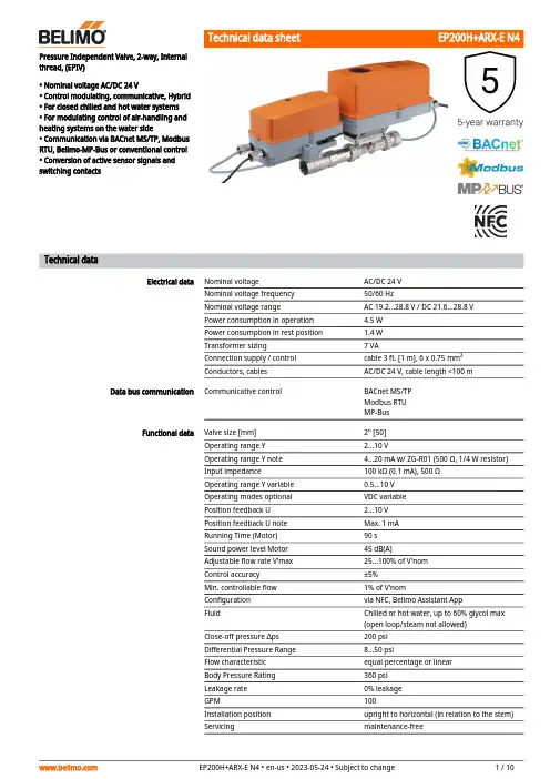
Pressure Independent Valve, 2-way, Internalthread, (EPIV)• Nominal voltage AC/DC 24 V• Control modulating, communicative, Hybrid• For closed chilled and hot water systems• For modulating control of air-handling andheating systems on the water side• Communication via BACnet MS/TP, ModbusRTU, Belimo-MP-Bus or conventional control• Conversion of active sensor signals andswitching contactsTechnical dataElectrical data Nominal voltage AC/DC 24 VNominal voltage frequency50/60 HzNominal voltage range AC 19.2...28.8 V / DC 21.6...28.8 VPower consumption in operation 4.5 WPower consumption in rest position 1.4 WTransformer sizing7 VAConnection supply / control cable 3 ft. [1 m], 6 x 0.75 mm²Conductors, cables AC/DC 24 V, cable length <100 m Data bus communication Communicative control BACnet MS/TPModbus RTUMP-BusFunctional data Valve size [mm]2" [50]Operating range Y 2...10 VOperating range Y note 4...20 mA w/ ZG-R01 (500 Ω, 1/4 W resistor)Input impedance100 kΩ (0.1 mA), 500 ΩOperating range Y variable0.5...10 VOperating modes optional VDC variablePosition feedback U 2...10 VPosition feedback U note Max. 1 mARunning Time (Motor)90 sSound power level Motor45 dB(A)Adjustable flow rate V'max25...100% of V'nomControl accuracy±5%Min. controllable flow1% of V'nomConfiguration via NFC, Belimo Assistant AppFluid Chilled or hot water, up to 60% glycol max(open loop/steam not allowed)Close-off pressure ∆ps200 psiDifferential Pressure Range8...50 psiFlow characteristic equal percentage or linearBody Pressure Rating360 psiLeakage rate0% leakageGPM100Installation position upright to horizontal (in relation to the stem)Servicing maintenance-free••••Mode of operationFunctional data Manual override external push button Measuring data Measured values FlowFlow measurementMeasuring principle Ultrasonic volumetric flow measurement Measuring accuracy flow ±2%Min. flow measurement 0.5% of V'nom Measurement Repeatability ±0.5% (Flow)Sensor TechnologyUltrasonic with glycol and temperature compensation Safety data Degree of protection IEC/EN IP66Degree of protection NEMA/UL NEMA 4EnclosureUL Enclosure Type 4Pressure equipment directive CE according to 2014/68/EU Quality Standard ISO 9001UL 2043 CompliantSuitable for use in air plenums per Section 300.22(C) of the NEC and Section 602 of the IMC Rated impulse voltage supply / control 0.8 kV Ambient humidity Max. 100% RH Ambient temperature -22...122°F [-30...50°C]Storage temperature-40...176°F [-40...80°C]MaterialsValve bodyNickel-plated brass body Flow measuring pipe brass body nickel-plated Valve plug Stainless steel Stem stainless steel Stem seal EPDM (lubricated)Characterized disc TEFZEL®SeatPTFE Pipe connection NPT O-ring EPDM Ballstainless steelSafety notesThis device has been designed for use in stationary heating, ventilation and air-conditioning systems and must not be used outside the specified field of application, especially in aircraft or in any other airborne means of transport.Outdoor application: only possible in case that no (sea) water, snow, ice, insolation or aggressive gases interfere directly with the actuator and that is ensured that the ambient conditions remain at any time within the thresholds according to the data sheet.Only authorized specialists may carry out installation. All applicable legal or institutional installation regulations must be complied during installation.The device contains electrical and electronic components and must not be disposed of as household refuse. All locally valid regulations and requirements must be observed.Product featuresThe HVAC performance device is comprised of three components: characterized control valve (CCV), measuring pipe with flow sensor and the actuator itself. The adjusted maximum flow (V'max) is assigned to the maximum control signal (typically 100%). The HVAC performance device can be controlled via communicative signals. The fluid is detected by the sensor in the measuring pipe and is applied as the flow value. The measured value is balanced with the setpoint. The actuator corrects the deviation by changing the valve position. The angle of rotation α varies according to the differential pressure through the control element (see flow curves).Flow measurement All flow tolerances are at 68°F [20°C] & water. Flow rate curvesControl characteristics The fluid velocity is measured in the measuring component (sensor electronics) and converted to a flow rate signal.The control signal Y corresponds to the power Q via the exchanger, the volumetric flow isregulated in the EPIV. The control signal Y is converted into a linear characteristic curve andprovided with the V'max value as the new reference variable w. The momentary controldeviation forms the control signal Y1 for the actuator.The specially configured control parameters in connection with the precise flow rate sensorensure a stable quality of control. They are however not suitable for rapid control processes, i.e.for domestic water control. U5 displays the measured flow as voltage (factory setting).Parametrizing V'max with ZTH:U5 refers to the respective V'nom, i.e. if V'max is e.g. 50% of V'nom, then Y = 10 V, U5 = 5 V.Parametrizing V'max with PC-Tool:In the PC-Tool, the maximum flow rate to which U5 refers can be set individually. If V'max ischanged (e.g. to 70% V'nom), the U5 flow range is also automatically changed to the same value(e.g. 70% V'nom: U5 = 10 V). This adjustment can be reversed by entering a value manually (U5flow range = 100%: U5 refers to V'nom).As an alternative, U5 can be used for displaying the valve opening angle.Creep flow suppressionConverter for sensorsControl signal inversionHydronic balancing Combination analogue - communicative(hybrid mode)Manual override Flow controlV'nom is the maximum possible flow.V'max is the maximum flow rate which has been set with the highest control signal DDC. V'maxcan be set between 25% and 100% of V'nom.Given the very low flow speed in the opening point, this can no longer be measured by the sensor within the required tolerance. This range is overridden electronically.Opening valveThe valve remains closed until the flow required by the control signal DDC corresponds to 1% of V'nom. The control along the flow characteristic is active after this value has been exceeded. Closing valveThe control along the flow characteristic is active up to the required flow rate of 1% of V'nom. Once the level falls below this value, the flow rate is maintained at 1% of V'nom. If the level falls below the flow rate of 0.5% of V'nom required by the control signal DDC, then the valve willclose.Connection option for a sensor (active or with switching contact). In this way, the analog sensor signal can be easily digitized and transferred to the bus systems BACnet, Modbus or MP-Bus. This can be inverted in cases of control with an analog control signal. The inversion causes the reversal of the standard behavior, i.e. at a control signal of 0%, is equal to V'max, and the valve is closed at a control signal of 100%.With the Belimo tools, the maximum flow rate (equivalent to 100% requirement) can be adjusted on-site, simply and reliably, in a few steps. If the device is integrated in the management system, then the balancing can be handled directly by the management system. With conventional control by means of an analog control signal DDC, BACnet, Modbus, or MP-Bus can be used for the communicative position feedback.Manual control with push-button possible - temporary. The gear train is disengaged and the actuator decoupled for as long as the button is pressed.AccessoriesTools Description TypeConverter Bluetooth / NFC ZIP-BT-NFCWire colors:1 = black 2 = red 3 = white 5 = orange 6 = pink 7 = greyFunctions:C1 = D- = A C2 = D+ = BElectrical installationSupply from isolating transformer.The wiring of the line for BACnet MS/TP / Modbus RTU is to be carried out in accordance with applicable RS485 regulations.Modbus / BACnet: Supply and communication are not galvanically isolated. Connect earth signal of the devices with one another.Modbus RTU / BACnet MS/TP with analogue setpoint (hybrid mode)BACnet MS/TP / Modbus RTUCable colors:1= black 2 = red 3 = white 5 = orange 6 = pink 7 = greyBACnet / Modbus signal assignment:C1 = D– = A C2 = D+ = BConnection with active sensor, e.g. 0...10 V @ 0...50°CPossible voltage range:0...32 V (resolution 30 mV)Connection with switching contact, e.g. Δp monitorRequirements for switching contact:The switching contact must be able to accurately switch a current of 16 mA @ 24 V.Operation on the MP-BusFunctionsFunctions with specific parameters (Parametrisation necessary)Operating controls and indicatorsLED display green On:Device starting upOff:No power supply or wiring error Flashing:In operation (Voltage ok)Flow direction NFC interfaceManual override button Press button:Gear train disengages, motor stops, manual override possible Release button:Gear train engages, standard mode. Device performssynchronisation.Cover, POP button POP buttonScale for manual adjustment Manual override button Press button:Gear train disengages, motor stops, manual override possible Release button:Gear train engages, standard modePush-button (LED yellow)Press button:Acknowledgment of addressingPush-button (LED Green)Press button:Triggers angle of rotation adaptation, followed by standard mode123423456Recommended installation positionsInstallation position in return Water quality requirementsServicing Flow direction Cleaning of pipes Prevention of stressesSetting fail-safe positionSetting emergency setting position (POP)Installation notesThe ball valve can be installed upright to horizontal. The ball valve may not be installed in ahanging position, i.e. with the stem pointing downwards.Installation in the return is recommended.The water quality requirements specified in VDI 2035 must be adhered to.Belimo valves are regulating devices. For the valves to function correctly in the long term, they must be kept free from particle debris (e.g. welding beads during installation work). The installation of a suitable strainer is recommended.Ball valves, rotary actuators and sensors are maintenance-free.Before any service work on the control element is carried out, it is essential to isolate the rotary actuator from the power supply (by unplugging the electrical cable if necessary). Any pumps in the part of the piping system concerned must also be switched off and the appropriate slide valves closed (allow all components to cool down first if necessary and always reduce the system pressure to ambient pressure level).The system must not be returned to service until the ball valve and the rotary actuator have been correctly reassembled in accordance with the instructions and the pipeline has been refilled by professionally trained personnel.The direction of flow, specified by an arrow on the housing, is to be complied with, since otherwise the flow rate will be measured incorrectly.Before installing the valve, the circuit must be thoroughly rinsed to remove impurities. The valve must not be subjected to excessive stress caused by pipes or fittings.Inlet sectionSplit installationBehaviour in case of sensor failureIn order to achieve the specified measuring accuracy, a flow-calming section or inflow section in the direction of the flow is to be provided upstream from the flow sensor. Its dimensions shouldbe at least 5x DN.The valve-actuator combination may be mounted separately from the flow sensor. The direction of flow of both components must be observed.General notesIn case of a flow sensor error, the EPIV will switch from flow control to position control.Once the error disappears, the EPIV will switch back to the normal control setting.DimensionsDimensional drawingsTypeWeight EP200H+ARX-E N415 lb [6.7 kg]ABCD E F26.6" [675]13.9" [353]12.0" [305]10.2" [260] 3.4" [86]3.4" [86]。
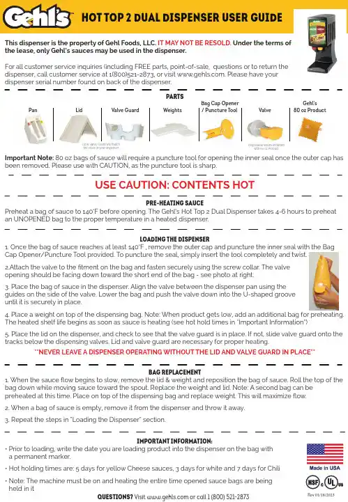
Hot Top 2 Dual Dispenser User GuideThis dispenser is the property of Gehl Foods, LLC. IT MAY NOT BE RESOLD. Under the terms ofthe lease, only Gehl’s sauces may be used in the dispenser.For all customer service inquiries (including FREE parts, point-of-sale, questions or to return thedispenser, call customer service at 1(800)521-2873, or visit . Please have yourdispenser serial number found on back of the dispenser.Pan Lid Valve Guard Weights Bag Cap Opener / Puncture Tool ValveGehl’s 80 oz Product Important Note: 80 oz bags of sauce will require a puncture tool for opening the inner seal once the outer cap has been removed. Please use with CAUTION, as the puncture tool is sharp.Lid & Valve Guard will matchthe color of your dispenser Disposable valves included with 80 oz Product USE CAUTION: CONTENTS HOTpre-heating sauce Preheat a bag of sauce to 140°F before opening. The Gehl’s Hot Top 2 Dual Dispenser takes 4-6 hours to preheat an UNOPENED bag to the proper temperature in a heated dispenser.PartsRev01/18/2023loading the dispenser 1.Once the bag of sauce reaches at least 140°F , remove the outer cap and puncture the inner seal with the BagCap Opener/Puncture Tool provided. To puncture the seal, simply insert the tool completely and twist.2.Attach the valve to the tment on the bag and fasten securely using the screw collar. The valveopening should be facing down toward the short end of the bag - see photo at right.3.Place the bag of sauce in the dispenser. Align the valve between the dispenser pan using theguides on the side of the valve. Lower the bag and push the valve down into the U-shaped grooveuntil it is securely in place.4.Place a weight on top of the dispensing bag. Note: When product gets low, add an additional bag for preheating.The heated shelf life begins as soon as sauce is heating (see hot hold times in “Important Information”)5.Place the lid on the dispenser, and check to see that the valve guard is in place. If not, slide valve guard onto the tracks below the dispensing valves. Lid and valve guard are necessary for proper heating.**NEVER LEAVE A DISPENSER OPERATING WITHOUT THE LID AND VALVE GUARD IN PLACE**bag replacement 1. When the sauce ow begins to slow, remove the lid & weight and reposition the bag of sauce. Roll the top of thebag down while moving sauce toward the spout. Replace the weight and lid. Note: A second bag can bepreheated at this time. Place on top of the dispensing bag and replace weight. This will maximize ow.2. When a bag of sauce is empty, remove it from the dispenser and throw it away.3.Repeat the steps in “Loading the Dispenser” section.important information:•Prior to loading, write the date you are loading product into the dispenser on the bag witha permanent marker.•Hot holding times are: 5 days for yellow Cheese sauces, 3 days for white and 7 days for Chili•Note: The machine must be on and heating the entire time opened sauce bags are being held in itquestions?Visit or call 1 (800) 521-2873HOlding temperature • Gehl’s dispensers hold sauce at 140°F (min) when the lid and valve guard are properly in placeon the dispenser.• Temperature check procedure: Remove the heated bag of sauce from the dispenser. Whileholding the bag upright, remove the valve from the bag. Insert a sanitized thermometer directlyinto the sauce through the bag opening.*THE THERMOMETER ON THE OUTSIDE OF THE DISPENSER DOES NOT REFLECT THE TEMPERATURE OF THE SAUCE.*maintenance • Every morning before using - clean the valve and remove any excess air from the valve.- Wipe down the outside of the dispenser with a damp, clean cloth.- Remove and wash the valve guard with a damp, clean cloth.• As needed - before cleaning the inside of the dispenser, unplug and let cool. Wipe down with a damp, clean cloth. - Dry thoroughly before plugging unit back in.sauce storage Gehl’ sauces are shelf stable. Store unopened bags below 90°F, DO NOT FREEZE.Refrigeration • If refrigeration is necessary, remove the valve from the bag and reseal with the original cap.• When refrigerating, product must be cooled rapidly. For food safety, sauce chilled to 70°F within 2 hours or less and 40°F within 4 hours.• Sauces may be held in refrigeration for up to 7 days if maintained between 38°F and 42°F.re-heating • When reheating for serving, sauce must be heated rapidly. For food safety, sauce must reach 165°F within 2 hoursbefore it can be served.**COOLED SAUCE WILL NOT ACHIEVE 165˚F WITHIN TWO HOURS IN THE DISPENSER**• Alternate heating methods: Steamer over or hot water bath. DO NOT boil or microwave bags.• NOTE: Sauce can only be cooled and reheated once per bag **FOR FOOD SAFETY, THE DISPENSER NEEDS TO REMAIN PLUGGED IN WHEN SAUCE IS IN DISPENSER**GEHL FOODS, LLC, PO BOX 1004 GERMANTOWN, WI 53022 · FOR NUTRITION FACTS VISIT: Free Parts and Replacements Program*Gehl’s will provide FREE replacement parts for the life of the dispenser. The lid, valve guard, inside pan, weights, push buttons, bag opener and puncture tool are all Free replacement parts. Even the shipping is FREE. If the unit stops heating or the main housing breaks within the rst 3 years, Gehl’s will provide a replacement dispenser to you for FREE. If it is within the rst year, even the shipping is FREE. If the unit is 2 to 3 years old, a fee for shipping and handling applies for the replacement to be sent to you, but the return shipping of the nonfunctioning dispenser is FREE. Also, Gehl’s point-of-sales (POS) material is FREE and includes FREE shipping.*Certain restrictions apply. FREE shipping is ground service within the continental U.S. only, using a carrier of Gehl’s choice; replacement dispensers may be remanufactured dispensers; and a FREE replacement is available only if your dispenser hasn’t been damaged due to misuse, negligence or misconduct. Contact Gehl’s for additional information. This program is subject to change without notice. *If you have any questions or issues, please call our customer service line toll free at 800-521-2873 and let us help you.。

The Future of Commercial Hot Water HeatingTable of ContentsO1. Introducing Heat2O and heat pump basics2. Heat23. Cold climate performance and scalability4. System design5. Installation requirements and maintenance6. Improved installation quality7. Controls and benefits for utilities8. Applications1Commercial hot water heating for the futureDomestic hot water accounts for roughly 25% of annual energy usage in typical multifamily buildings 1 and 25% in both passive house 2 and new, multifamily construction 3. This energy expenditure is costly for building owners and comes at a significantenvironmental impact in the form of greenhouse gas emissions and climate change.Until recently, the building industry lacked an energy-efficient solution to providing high volume domestic hot water (DHW) for commercial spaces. In response to this need, we’re pleased to introduce the Heat 2O™ Hot Water Heat Pump, a revolution in sustainable water heating.Introducing Heat2OHeat 2O is an all-electric heat pump water heaterdesigned to produce high volume DHW for commercial facilities in any climate. Energy-efficient andenvironmentally friendly, Heat 2O uses a natural CO 2 refrigerant with a global warming potential (GWP) of one and an ozone depletion potential (ODP) of zero.As an engineered solution with manufacturer-level technical support, Heat 2O is fully customizable to best meet the design considerations and priorities of a broad array of application types. This technology can help multifamily buildings, offices, gyms, educational institutions and other large-scale and commercial facilities qualify for sustainability certifications or achieve zero-energy and passive house status. The system’s environmentally conscious engineering also translates to energy savings for building owners, who experience reduced operating costs while their tenants and occupants enjoy reliable hot water.These benefits can be enjoyed regardless of location. Climate zone is not a limiting factor for this innovation, as Heat 2O’s high-performance design allows the system to operate at high capacity even in cold climates.Buildings from the hot American Southwest to snowy New England can experience high performance and energy savings with Heat 2O, all while minimizing their carbon footprint.1 U.S. Energy Informational Administration2 Passive House Institute US3 Bonneville Power Administration2Heat2O™ and heatpump basicsDHW heat pump water heaters transfer ambient thermalenergy from outdoor air to potable water by cyclingrefrigerant. Natural CO2refrigerant enables Heat2Oto supply hot water up to 176° F even in low ambientconditions. The heat pump’s fan pulls outdoor air acrossan evaporator coil where liquid refrigerant absorbs heatas it changes to a low-pressure gas. With the refrigerantcarrying heat captured without burning fossil fuels, theheat pump’s compressor pressurizes the gas raising thetemperature and transfers the refrigerant to a gas cooler.The gas cooler then transfers heat from the superheatedrefrigerant gas to the incoming city water. This isaccomplished without the use of fossil fuels reducing thecarbon footprint associated with water heating.Heat2O uses a Twisted Spiral Gas Cooler unique toMitsubishi Electric. This patented technology achieveshighly efficient heat exchange with three refrigerantlines wrapped around a twisted water pipe. Therefrigerant flows in the opposite direction of the water.Running the refrigerant lines along the pipe’s groovesincreases the heat conductive area while the spiral helpscreate a vortex in the pipe, accelerating the turbulenceeffect of water and reducing pressure loss in the heatexchanger. Additionally, the copper pipes make fordouble-walled construction.An INVERTER scroll compressor further increases Heat2O’senergy efficiency by enabling the system to modulatethe refrigerant flow and heating capacity to match loads.Variable capacity gives the system greater control overenergy use than fixed-capacity hot water heat pumps.Using these methods, Heat2O offers a coefficient ofperformance (COP) of up to 4.52, meaning it can provideover four times more energy as heat than it consumes inelectricity. Compared to electric-resistance water heaters,Heat2O offers energy savings of 60 to 70% for buildingowners and tenants. Combined with incentives fromutilities, energy savings can ultimately offset first costs.3Cold-climateperformance and scalabilityFlash injection circuitHeat 2O continues to deliver 100% heating capacity at ambient temperatures of 36° F and can supply 176° F hot water at temperatures as low as -13° F . This performance is achieved through flash-injection technology. In extreme cold, Heat 2O’s compressor operates at speeds much higher than usual tomaintain discharge pressure and keep the evaporator’s refrigerant cool enough to capture ambient heat. The injection circuit supplies a small amount of mixed-phase refrigerant to the compressor through a specially designed port, ensuring stable operation at highspeeds. With Heat 2O, even building owners in climate zones 5 and 6 can increase sustainability while reducing energy costs for high-volume DHW. Performance:• 100% water heating capacity of 40 kW at ambient temperatures as low as 36° F• 50% water heating capacity at ambient temperatures as low as -13° F (176° F water temperature)ScalabilityHeat 2O can provide highly efficient DHW for most commercial buildings, including large-scale facilities. Using Mitsubishi Electric’s unique Mitsubishi Network (M-NET) communication protocol, the system can be scaled, connecting up to 16 Heat 2O units together. While nominal system capacity is 40 kW (136,484 BTU/H), M-NET allows all units to communicate with one another, enabling cascade operation and acombined total capacity of 2,183,770 BTU/H (640 kW). Units run at the same compressor frequency to achieve a stable leaving water temperature set point. Thislevel of performance is ideal for applications requiring high volumes of hot water on-demand, including universities, hotels and other large facilities.64,83051,180OUTDOOR TEMPERATURECAPACITY (BTU/H)Heating CapacitySystem designOptimal performance and cost benefits for all-electric heat pumps require proper design, installation and commissioning. This starts with cooperation and information exchange among project team members, including the developer or building owner who will decide whether the facility will participate in utility demand-response programs. Designers must understand the building’s demand profile, inclusive of the gallons per hour, duration and timing associated with peak loads and off-peak loads. The system’s storage capacity is based on how often the system will run. Additionally, designers account for climate and may make provisions for snow, rain, wind and marine salt.The Heat2O project team typically includes plumbingengineers, electrical engineers and control engineers. Each trade and discipline should be involved in the earliest stages of the project. The team will also include Trane®/Mitsubishi Electric employees responsible for thestartup and commissioning of each Heat2O system.Design for hot waterrecirculationHeat2O designs account for hot water recirculationby separating DHW loads. The heat pump waterheater handles the difference between the inlet citywater temperature and the leaving temperature. Therecommended inlet temperature range is 41° F to145° F, but a high Delta T between inlet and outlettemperatures provides optimal efficiency.The building’s recirculated water is warmer than inletcity water and is often outside the optimal temperaturerange recommended for the heat pump. To avoidderating and ensure the availability of hot water, Heat2Odesigns include a primary storage tank and a swingtank. Heat2O conditions the cool incoming city waterat the bottom of the primary storage tank while thehot water moves to the top, maintaining temperaturestratification. During hot water production, the systemcan feed high-temperature water to the swing tank,which also mixes with warm recirculation water. Waterwithin the swing tank is maintained within a specifiedtemperature range, for example 125° F to 150° F. TheHeat2O swing tank includes a control panel with threeelectric heating elements for temperature maintenance.Typical Systems SchematicTANK PUMP HOT WATER RECIRCULATING PUMP45Heat 2O is typically installed outdoors with common considerations for airflow, space, structural support, acoustics and service access common to heat pumps. Each Heat 2O unit must be individually wired to its own dedicated power supply and have one-foot minimum clearance for air intakes. Installation of cold-water inlet and hot-water outlet piping is straightforward.MaintenanceMaintenance primarily consists of maintainingcleanliness. Install a strainer near the Heat 2O unit to keep foreign materials from entering the water-side heat exchanger. Clean the external heat exchanger, clean strainers periodically and ensure the internal heat exchanger and secondary heat exchanger are free ofscaling and debris.Heat 2O at a glance• Height: 72.5"• Width: 48"• Depth: 30"• Weight: 882 lbs • Electrical: 208/230V • Sound: 60 dB(A), no louderthan a conversationInstallation requirements and maintenance6Improved installation qualityAs a custom solution, Heat 2O includes a complement of parts designed and selected to ensure optimal performance of the heat pump. Using pre-approved parts help control the quality of installations and streamlines the work with pre-assembled and pre-plumbed components.Hot water storage tanksPrimary storage tank: Includes 6 thermistor locations for more precise measurement of water temperatures compared to most storage tanks, which typically have one thermistor.• Sizes: 175 gallons, 285 gallons, 500 gallonsSwing tank: Includes electric-resistance elements for the ability to maintain specific temperatures in the swing tank and can provide up to 100% backup capacity for the heat pump.• Sizes: 150 gallons (with 45 kW electric-resistance element) and 200 gallons (54 kW electric-resistance element)Secondary heat exchanger: Creates a closed loop to protect Heat 2O from scaling and corrosion from city water, reducing maintenance requirements.Variable-speed secondary circuit pumps: Varies capacity on secondary circuit according to demand. The speed is controlled using a 0 to 10V signal from the Heat 2O units.Heat 2O Components and TanksEXTERNAL COMPRESSORSTORAGE TANKS SWING TANK HEAT EXCHANGER7Controls and benefitsfor utilitiesComprehensive control for efficient operationA pre-engineered controls package is available to further enhance Heat 2O’s operation and efficiency. This package seamlessly integrates the heat pumps, tanks, pumps, valves and sensors to monitor and control the system. No additional programming or licenses are required to add the controls to the hardware. An interactive setup guide makes the startup and commissioning process intuitive and easy to follow. Local users can monitor and control operation, modes, set points and tank capacities with the touch screen display through the site local area network or through BACnet ® integration to a building management system (BMS). The built-in Energy Monitoring Capabilities and Demand Response Rebate Program (CTA-2045) enables Heat 2O to react to demand-response signals from grid operators. Internet access and increased capabilities are available through connection to the Building Connect + cloud-based controls platform.Building Connect + features:• On/Off mode, temperature mode control and tank temperature set point • Start-up wizard • Maintenance tool data • Flow diagram • Energy use dashboard • Data trending • Alarm managementDemand response and utility benefitsDuring demand-response events, utilities shift energy use to prevent electricity grids from overloadingduring peak usage times. Building owners can qualify for utility incentives by participating in demand-response programs. Able to send and receive messages defined by the CTA-2045 specification, Heat 2O can simplify participation with a utility virtual end node integrated into the system’s control panel.Heat 2O units operate at 40 kW in normal mode. In advance of demand-response events, the system can run at 60 kW in capacity mode to fully pre-load tanks with hot water. Once the tanks are depleted, Heat 2O can reactivate so building occupants have uninterrupted access to hot water. Primary thermal storage tanks with swing tanks for recirculated water enable the system to handle a higher peak demand.8HEAT 2OSEALED HOT WATER STORAGE TANKS X 3HOT WATERRECIRCULATION PUMPMIXING VALVESECONDARY HEAT EXCHANGERSECONDARY PUMPSWING TANKApplicationsMultifamily (Hot Water Recirculation - Swing Tank Required)Fitness Center (No Hot Water Recirculation - No Swing Tank)HEAT 2OCITY WATER CONNECTIONSTORAGE TANKOutlet hot water piping Inlet water pipingSECONDARY HEAT EXCHANGERSTOutlet hot water pipingInlet water pipingSpecificationsQAHV-N136TAU-HPB-(-BS)Notes: Unit converter*1.Under Normal heating conditions at the outdoor temp, 16°CDB/12°CWB(60.8°FDB/53.6°FWB), the outlet water temperature 65°C(149°F), and the inlet water temperature 17°C(62.6°F)*Do not use steel pipes as water pipes.*Keep the water circulated at all times. Blow the water out of the pipes if the unit will not be used for an extended period time.*Do not use ground water or well water*Do not install the unit in an environment where the wet bulb temperature exceeds 32°C*The water circuit must use the closed circuit*There is a possibility that the unit may abnormally stop when it operates outside its operating range. Provide backup(ex.boiler start with error display output signal (blue CN511 1-3)) for abnormal stop.9®TR_CM_2001_3-2210。

热浇道系统简介现时常见的热浇道系统,主要由分流板、热咀和温度控制器三大部份组成。
热浇道系统是透过精密的温控手段,将熔融塑料通过精密设计的分流板和热嘴,直接输送至模腔里,其好处包括:有效减低浇道的压力;熔体的流动性得到提高;材料密度均匀;产品的内应力减少,使产品获得较小的变形、较好的产品表面质量和力学性能。
热浇道系统的另一特点,是热嘴直接将熔融塑料注入模腔内,在脱模的过程中,浇口自然断开,消除了传统注塑工艺带来的浇道废料,除免去处理浇道废料的后加工工序外,更消除了废料所带来的附加热量,缩短冷却时间,获得更快的生产周期。
热浇道技术已成熟要获得理想的注塑效果,热浇道需要确保其内的塑料熔体在注射、保压和冷却阶段保持正确的温度。
最早期的热浇道系统,在温度控制上未臻完善,随着后期的逐步改良,现时的热浇道技术已相当成熟。
本文会简介热浇道的发展简史和其基本结构,希望加深读者对这方面的认识。
绝缘式浇道系统绝缘式浇道系统是最早期的热浇道系统,其工作原理是昨用塑料本身极低的热传递系防止热量散于失于模板中,以保持塑料的熔融状态。
在浇道的设计上,口径尽量加大,以使浇道中央的塑料在首次充填后,借着塑化材料不断地流通而保持熔融。
至于浇道最外层接触模板的塑料,会因遇冷而凝结成固化层,在固化层中间就是不断流通的塑料通道。
一旦形成固化层,在熔融塑料与模板间会产生不错的绝热效果,足以确保熔融塑料在快速连续地生产下不致发生浇道全面凝结。
但是只要有任何短暂的生产停顿,还是不能避免整条浇道的固化。
绝缘式浇道难于控制熔融塑料温度这种原始的热浇道系统难于控制熔融塑料的温度,导致浇道冷凝与浇口阻塞的现象不断发生。
为了解决此问题,就有了热探捧的出现,即在浇口前的通道中,加装一支管形加热器,藉此控制熔融塑料的温度,同时,浇口的控制、成品的顶出均获得改善。
事实上,早期的绝热式浇道系统只适用于低黏度塑料,随着高黏度及成型性较差的工程塑料的不断出现,对流动通道中熔融塑料的温度控制也越重要,所以又衍生出歧管式浇道系统。
热流道的原理及应用图解1. 热流道的定义热流道(Hot Runner)是一种塑料模具的加热系统,它通过将热能传输给模具中的塑料来加热塑料,使其融化成型。
相比于传统的冷流道(Cold Runner)系统,热流道系统具有更高的生产效率和更好的产品质量,被广泛应用于塑料制品的生产过程中。
2. 热流道的工作原理热流道系统由一套加热系统和流道系统组成,其工作原理如下:2.1 加热系统热流道的加热系统一般由加热器、热流道管和热流道控制器组成。
加热器通过加热元件将电能转化为热能,使热流道管内的热媒介(通常是热油)被加热。
热流道控制器可以实现对热流道的温度、流量等参数进行精确控制。
2.2 流道系统流道系统是热流道的关键组成部分,它负责将加热过的热媒介传递给模具中的塑料。
流道系统通常由主流道、分流道和喷嘴组成。
•主流道:主流道是热流道中最重要的一部分,它负责将加热过的热媒介传递给分流道和喷嘴。
主流道的尺寸和布置对于塑料的流动和充填起着重要作用。
•分流道:分流道将主流道中的热媒介分流到各个喷嘴上,使得每个喷嘴都能独立地控制塑料的温度和流量。
•喷嘴:喷嘴是塑料的最后成型部分,它负责将加热的塑料注入到模具腔中。
3. 热流道的优势和应用相比于冷流道系统,热流道系统具有以下优势:3.1 提高生产效率由于热流道系统中的热媒介可以保持在适宜的温度,使得塑料在注射过程中保持良好的流动性,从而减少了注射时间和冷却时间,提高了生产效率。
3.2 降低生产成本热流道系统减少了冷却时间和废品产生,降低了生产成本。
同时,由于去除了冷道系统,可以减少注塑机的锁模力,降低了设备的投资成本。
3.3 改善产品质量热流道系统可以精确控制塑料的温度和流量,保证了每个喷嘴注入的塑料质量一致,减少了产品的热变形和缺陷。
热流道系统在以下领域有广泛的应用:•医疗器械:热流道系统被广泛应用于制造医疗器械,如注射器、输液器等。
由于产品的精度和质量要求较高,热流道系统能够满足其生产需求。

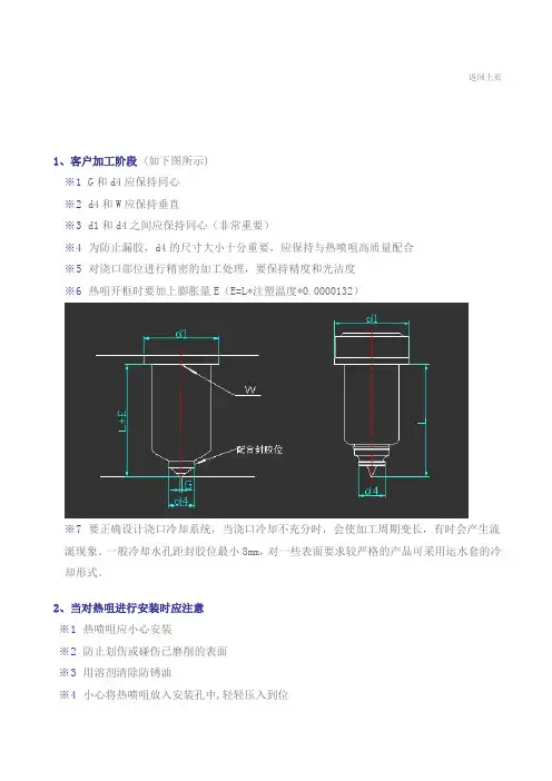
返回上页1、客户加工阶段(如下图所示)※1 G和d4应保持同心※2 d4和W应保持垂直※3 d1和d4之间应保持同心(非常重要)※4 为防止漏胶,d4的尺寸大小十分重要,应保持与热喷咀高质量配合※5 对浇口部位进行精密的加工处理,要保持精度和光洁度※6 热咀开框时要加上膨胀量E(E=L*注塑温度*0.0000132)※7 要正确设计浇口冷却系统,当浇口冷却不充分时,会使加工周期变长,有时会产生流涎现象。
一般冷却水孔距封胶位最小8mm,对一些表面要求较严格的产品可采用运水套的冷却形式。
2、当对热咀进行安装时应注意※1 热喷咀应小心安装※2 防止划伤或碰伤已磨削的表面※3 用溶剂清除防锈油※4 小心将热喷咀放入安装孔中,轻轻压入到位※5 在安装完毕前,将导线放入线槽中,不要用导线拉动或转动热喷咀,安装时要确保加热丝和热电偶的导线不会被过分折弯或被破坏※6 在一模多腔情况下,检查确保所有热喷咀的W面在同一平面(平面度误差为+/-0.02) ※7如图所示,保证热喷咀与模具在接触时维持最小接触面积※8 检查所有热喷咀安装高度,确保正确后热分流板方可被装入模具中,一切就绪后再安装O型金属密封圈。
※9 当加热到设定温度后,用一条软线(如保险丝线)检查热喷咀在热状态后咀尖与浇口之间的间隙,周围的间隙必须保证均匀,如果没有间隙或者间隙太小(小于0.2mm),请检查浇口规格和E值计算结果是否正确.※10 安装后都要对电路控制系统进行检查,以确保能正常运行。
(用万用表检测)3、安装热分流板按以下程序正确计算热喷咀和热分流板的膨胀量,是防止漏胶的重要条件:※1 测量热分流板、钢垫块、钛合金垫块、L的总高度。
※2 然后测量整个为安装热喷咀及热分流板所制作的空间,使尺寸完全达到要求,如测量从W面到定模固定板(底板)的高度等等。
※3 在工作温度下,热分流板钛合金垫块与定模固定板(底板)之间有0.05mm的过盈量,这个距离通过磨削钢垫块进行调整。
12Make connections to water lines. Use 1/2" IPS faucet connections (1) Use wrenches to tighten connections. Do not overtighten.Important: After installation is completed, remove aerator. Turn on water supply and allow both hot and cold water to run for at least one minute each. While water is running, check for leaks. Replace aerator.Place gasket (1) on bottom of new faucet. Place faucet through mounting holes in sink. Secure faucet to sink using mounting nuts (2) provided.Shut off water supply at angle stop. Remove old faucet.Clean sink surface in preparation for new faucet.1STEPS:WARNING: Please carefully read and properly follow the instructions for installation found in this manual.33Shut off water supply.Remove handle(refer to step 1).Loosen bonnet (1) by turning it counter-clockwise and lift out the cartridge (2).Inspect the rubber valve seat (3) inside body (4).Make sure the wings (5) on the two sides of the cartridge bonnet fit well into the slots (6) on the body.Tightly bonnet (1).Reinstall the handle.Turn off water before proceeding! Remove index(1).With valves in "closed" position,unscrew fastener (2) and remove handle (3) from valve stem (4).5644FOR CARE AND MAINTENANCE:·The water in certain areas of the world can be very caustic - standing water around the product can cause damage. Be sure to remove standing water with a dry, soft cloth as soon as possible.·For polished brass finishes, as often as once a week, you can apply a paste wax or special, non-abrasive, brass coating (DO NOT APPLY POLISH).·Before applying a protective coating, gently brush the entire fixture using a soft tooth brush. This will remove any dirt or deposit build-up.·These simple steps will add temporary protective coating to your faucet and extend the life of the finish.Failure to follow care and cleaning will void your warranty. For additional information, please visit .Congratulations on your purchase of an Elkay product.Although your product is extremely durable, attention should be given to the care, cleaning and maintenance of thisproduct. Cleaning agents and abrasives may cause damage, which may result in oxidation and discoloration.By following these simple guidelines for proper care and cleaning, it will give you years of enjoyment:TO CLEAN: Simply wipe gently with a damp cloth and blot dry with a soft towel. A common rule of thumb is: when you dry off, dry off your product.· Avoid build-up of soap, toothpaste or mineral deposits, as these tend to have an adverse effect on the appearance of the product.· NEVER use cleaning products of any kind on this product - especially those containing ammonia, bleach or alcohol - or those with any form of abrasive.CARE AND CLEANING INSTRUCTIONS2121CARTRIDGE REPLACEMENTWhat is not covered:1. Damage caused by accident, negligence, misuse, abuse, improper installation or operation or failure to follow care or installation instructions enclosed with your product.2. Damage occurring during shipment of the product (claims must be presented to the carrier).3. Normal wear and tear.4. Labor charges, costs of removal and reinstallation, and any damages to other property.5. All industrial, commercial and business use whose purchasers are hereby extended a limited lifetime on mechanical parts and 5 years on finish.THIS LIMITED WARRANTY IS EXPRESSLY IN LIEU OF ANY OTHER WARRANTIES, EXPRESSED IMPLIED, ARISING BY LAW OR OTHERWISE, INCLUDING WITHOUT LIMITATION, ANY IMPLIED WARRANTY OF MERCHANTABILITY OR FITNESS FOR APARTICULAR PURPOSE. THIS LIMITED WARRANTY MAY NOT BE ALTERED, VARIED, OR EXTENDED, EXCEPT BY A WRITTENINSTRUMENT EXECUTED BY ELKAY. THE REMEDY OF REPAIR OR REPLACEMENT AS PROVIDED UNDER THIS LIMITED WARRANTY IS EXCLUSIVE. IN NO EVENT SHALL THE MANUFACTURER BE LIABLE FOR ANY CONSEQUENTIAL OR INCIDENTAL DAMAGES TO ANY PERSON, WHETHER OR NOT OCCASIONED BY NEGLIGENCE OF ELKAY, INCLUDING WITHOUT LIMITATION DAMAGES FOR LOSS OF USE, COSTS PROPERTY DAMAGE OR OTHER MONETARY LOSS.Some states do not allow the exclusion or limitation of incidental or consequential damages or limitations on how long an implied warranty lasts, so the above limitations or exclusions may not apply. This warranty gives you specific legal rights and you may also have other rights which vary from state to state.This warranty covers product installed in the United States and Canada RP50098 Set Screw RP10005 Index (B)RP38205 AeratorRP64085 Wearable RingRP64061 Inverter H RP64062 Inverter C P36164 ScrewRP10004 Index (R)RP13146 HandleRP60008 O-RingP35300 WasherP36160 Mounting NutRP22008 Seat & SpringRP22010 Cartridge RP70193 Bonnet RP70106 Ring What you must do to obtain warranty service:6245 Shiloh Rd, Suite B, Alpharetta, GA 30005 or call 866-237-3907 . Please provide date of purchase and installation, description of natureof the defect, and model number ordescription of model and/or component part.Elkay©2018 ElkayModel # LK2477CR (Rev. date: 09/18)REPLACEMENT PARTSElkay warrants that all parts and finishes of the Elkay Residential brand faucets are free from defects in materials and workmanship for the life of the product, if purchased after 1996. This warranty extends to the original consumer purchaser of the product only.If the product should leak or drip during normal use, Elkay will provide, free of charge, a replacement cartridge. For other defects in material or workmanship, Elkay will, at its option, supply replacement parts (or if no longer available a comparable product). Elkay reserves the right to examine product in question and its installation prior to replacement.WARRANTYELKAY LIMITED LIFETIME WARRANTY。
第四节热流道浇口的类型和结构一、开放式浇口:开模时,浇口中的部分材料留在产品上,从而造成了一个难看的浇口痕迹(通常是锥形的)。
浇口残痕的大小和形状取决于浇口的形状及注塑参数(温度,压力,时间),也取决于模具的设计,同样或甚至更多地取决于模具装配。
在下一次循环时,塑料料流将模塞(上一啤浇口处冻结的料)挤入型腔,浇口又打开,料流又可以填充模具,通常情况下模塞可以熔化,与注入塑料混合;在浇口对面做一弧形缩窝,有利于模塞的隐藏,有利于填充。
适用于没有或几乎没有“拉丝”倾向的塑料,还适用于PP种PE料。
开式浇口有三种基本类型:圆形浇口,环形浇口,边缘浇口。
1.1)圆形浇口:缺点:浇口L段的断开点不确定,可能会在L方向上的任一点断,并在产品上留下一很长的突起。
优点:这种浇口较易于加工制造。
此时,将浇口形状修改成下面的形状,则断点一致,在高于产品的锥形突起部位断开,虽然,在断点上还会有一个小锥形突起,但总的突起部分或多或少可以预测。
于控制热损失的开式浇口设计1.2)环形浇口:实质是一个在其中心部加入加热探的开式浇口,以防止过早冻结。
需要注意的是浇口形状与注嘴梢部的开状密切相关。
下图是在浇口中心有一个加热探头的环形浇口,由于注嘴梢位于浇口内而形成了一个环形通道,进入模具腔的塑料就像一个挤出的管子。
塑料充满了注嘴和其周围(冷却的)模腔之间的不导体,几乎不会有什么热量穿过这层塑料隔热罩。
在成型热稳定性差的塑料时,需要成型一个或机加工一个耐高温的塑料隔热罩,现一般是用杜邦Vespel 全芳香族聚酰亚胺(PI)塑料制作。
Vespel 的特点:1. 耐热性:连续使用耐热温度可达288°C ,短时间使用更可高达480°C 。
2. 耐磨耗性:Vespel 的无润滑限界PV 值是一般工程塑料的10倍以上,对冲击磨耗和摇动磨耗都有很强的耐性。
3. 蠕变(Creep):在260°C 、186kg/cm2条件下的蠕变,1000小时只有0.6%。
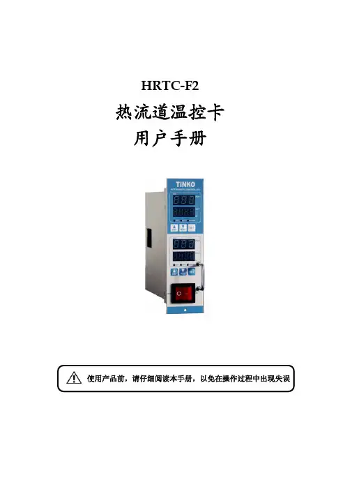
热流道控制器用户使用说明书产品使用前,请仔细阅读说明书,以便正确使用,并妥善保存,以便随时参考。
断电后方可清洗仪表。
清除显示器上污渍请用软布或棉纸。
显示器易被划伤,禁止用硬物擦拭或触及。
禁止用螺丝刀或书写笔等硬物体操作面板按键,否则会损坏或划伤按键。
1.在使用前先检查控制器⑴检查控制器的配件是否齐全⑵检查电源是否安全受控⑶检查此说明书是否与控制器匹配⑷检查连接器是否安全可靠⑸检查加热器是否安全可靠⑹检查主电源是关闭的⑺检查电源是否适合控制器的工作⑻确定地线连接控制器⑼打开主电源开关⑽打开各个控制器工作开关⑾设定控制温度⑿检查控制器是否达到设定温度,且稳定2. 控制器输出⑴PID控制通过测量实际温度和设定温度进行比较,精确计算比例、微分、积分值,控制输出电压⑵自整定通过分析加热器和加热模式排除环境变化调整控制参数⑶输出模式根据电源环境确定●50赫兹●60赫兹3. 技术参数输入电压:AC 85V-250V,50/60HZ,15A负载能力:15A,150W-1650W(110V),100W-3300W(220V)输出类型:PWM传感器:热电偶(K \ J)温度范围:100℃~400℃温度稳定性:±0.5%温度控制类型:PID 控制环境温度:-10℃~50℃4.面板布局1.指示灯:状态指示灯(STATE):软启动常亮,预整定1秒闪烁,自整定0.5秒闪烁,其他状态不亮。
输出指示灯(OUT):指示输出的的状态。
自动指示灯(AUTO):指示自动模式被选择。
等待指示灯(STANDBY):指示等待模式被选择。
手动指示灯(MANUAL):指示手动模式被选择。
2.数码管:PV数码管,红色,显示测量温度和参数代码。
SV数码管,红色,显示设定值和参数代码值。
3.按键::输入键:模式键:AUTO、STANDBY、MANUAL模式转换键:增加键:减小键5.操作模式通过按SEL键1秒钟以上可以进入以下模式。
⑴自动模式:正常的PID控制,在正常的设定值上。
Doc. no.SX10-OMR0002-AHigh Speed 2 Port ValveSX10 SeriesSafety Instructions ..................................................................................... 2,3 Design (4)Selection (4)Mounting (4)Wiring (4)Lubrication (5)Air Supply (5)Operating Environment (5)Maintenance (5)Precautions (6)Continuous Energization (6)Energizing Time and Non-Energizing Time (6)Others (6)Lead Wire Connection (6)Symbol (6)Wiring (6)Control method (7)Trouble shooting ······················································································· 8,9-1-Safety InstructionsThese safety instructions are intended to prevent hazardous situations and/or equipment damage.These instructions indicate the level of potential hazard with the labels of “Caution,” “Warning” or “Danger.” They are all important notes for safety and must be followed in addition to International Standards (ISO/IEC)*1), and other safety regulations.*1) ISO 4414: Pneumatic fluid power -- General rules relating to systems. ISO 4413: Hydraulic fluid power -- General rules relating to systems.IEC 60204-1: Safety of machinery -- Electrical equipment of machines .(Part 1: General requirements)ISO 10218-1992: Manipulating industrial robots -Safety. etc.Caution Caution indicates a hazard with a low level of risk which, if not avoided, could resultin minor or moderate injury.Warning Warning indicates a hazard with a medium level of risk which, if not avoided, could result in death or serious injury.DangerDanger indicates a hazard with a high level of risk which, if not avoided, will resultin death or serious injury.-2-Safety InstructionsLimited warranty and Disclaimer/Compliance RequirementsThe product used is subject to the following “Limited warranty and Disclaimer” and “Compliance Requirements”.Read and accept them before using the product.Limited warranty and Disclaimer1.The warranty period of the product is 1 year in service or 1.5 years after the product is delivered, whichever is first.∗2)Also, the product may have specified durability, running distance or replacement parts. Please consult your nearest sales branch.2. For any failure or damage reported within the warranty period which is clearly our responsibility,a replacement product or necessary parts will be provided.This limited warranty applies only to our product independently, and not to any other damage incurred due to the failure of the product.3. Prior to using SMC products, please read and understand the warranty terms and disclaimers noted in the specified catalog for the particular products.Compliance Requirements1. The use of SMC products with production equipment for the manufacture of weapons of massdestruction (WMD) or any other weapon is strictly prohibited.2. The exports of SMC products or technology from one country to another are governed by therelevant security laws and regulations of the countries involved in the transaction. Prior to the shipment of a SMC product to another country, assure that all local rules governing that export are known and followed.CautionSMC products are not intended for use as instruments for legal metrology.Measurement instruments that SMC manufactures or sells have not been qualified by type approval tests relevant to the metrology (measurement) laws of each country.Therefore, SMC products cannot be used for business or certification ordained by the metrology (measurement) laws of each country.-3-SX10-OMR0002-ADesign/Selection1. Review the specifications.The product is designed for use only in compressed air systems. Do not operate at pressures or temperatures, etc., beyond the range of specifications, as this can cause damage or malfunction. (Refer to the specifications shown in the catalog.) Please contact SMC if using for fluids other than compressed air. We do not guarantee against any damage if the product is used outside of the specification range.2. VentilationProvide ventilation when using a valve in a confined area, such as in a closed control panel. For example, install a ventilation opening, etc. in order to prevent pressure from increasing inside of the confined area and to release the heat generated by the valve.3. Disassembly and modification is prohibited.Do not disassemble the product or make any modifications, including additional machining.This may cause human injury and/or an accident.4. Air qualityUse clean air.Do not use compressed air that contains chemicals, synthetic oils, including organic solvents, salt or corrosive gases, etc., as it may cause damage or malfunction.For detailed information regarding the quality of the compressed air described above, refer to SMC's "Air Cleaning Systems".5. Ambient environmentUse within the operable ambient temperature range. After confirming the compatibility of the product's component materials with the ambient environment, operate such that fluid does not adhere to the product's exterior surfaces.6. Countermeasures against static electricityTake measures to prevent static electricity since some fluids can cause static electricity.1. Leakage voltageWhen a resistor and a switching element are used in parallel or C-R device (surge voltage suppressor) is used for the protection of the switching device, note that leakage voltage will increase because earth leakage current passes through the resistor and C-R device. The suppressor residual leakage voltage should be 0.2 VDC or less.2. Low temperature operationWhen using the valve in a low temperature condition, take appropriate measures to avoid freezing of thedrainage, moisture, etc. at low temperatures. Unless specified, the valvecan be used down to -10oC.3. Mounting orientationMounting orientation is not specified.Mounting1. Operation Manual (this copy)Install and operate only after reading the operation manual carefully and understanding the contents.Keep the manual handy, so that it can be referred to as necessary.2. Maintenance spaceWhen installing the products, allow access for maintenance.3. Observe the tightening torque for screws.Tighten the screws to the recommended torque, when mounting the product.4. If air leakage increases or equipment does not operate properly, STOP operation.After installation and maintenance, apply air and power supplies to the equipment and perform appropriate functional and leakage inspections to make sure the equipment is mounted properly.5. Painting and coatingWarnings or specifications printed or labeled on the product should not be erased, removed or covered.Please consult with SMC before applying paint to resinous parts, as this may have an adverse effect due to the solvent in the paint.6. Do not apply external force to the coil section.7. Do not warm the coil assembly with a heat insulator, etc.Use tape, heaters, etc., for freeze prevention on the piping and body only. Heating the coil may burn it out.8. When there is a vibration source close to the product, take anti-vibration measures.Wiring1. Polarity.Valves of this series can be either polarity.2. External force applied to the lead wireExcessive force to the lead wire may cause a broken wire. Make sure that no excessive force larger than 15 N is applied to the lead wires.SX10 SeriesPrecautions 1Be sure to read this before handling.Lubrication1. LubricationDo not supply oil.Air Supply1. Type of fluidsPlease consult with SMC when using the product in applications other than compressed air.2. Large amount of condensateCompressed air containing a large amount of condensate can cause malfunction of pneumatic equipment. An air dryer or water droplet separator should be installed upstream from filters.3. Draining controlIf condensate in the drain bowl is not emptied on a regular basis, the condensate will overflow and enter the compressed air lines. This will cause a malfunction of pneumatic equipment. If the drain bowl is difficult to check or remove, installation of a drain bowl with an auto drain option is recommended.4. Use clean air.Do not use compressed air that contains chemicals, synthetic oils, including organic solvents, salt or corrosive gases, etc., as it can cause damage or malfunction.For detailed information regarding the quality of the compressed air described above, refer to SMC's "Air Cleaning Systems".1. If ultra dry air is used as a fluid, the lubrication characteristics of the equipment will deteriorate and this can affect the reliability (life) of the product. Contact SMC beforehand, if using ultra dry air.2. Install air filters.Install air filters close to valves on the upstream side.It is strongly recommended to use a filter with a filtration rating of 0.01 μm or less. Be careful to prevent the supply pressure to the valve from decreasing.3. Take appropriate measures to ensure air quality, such as by providing an after cooler, air dryer, or water separator.Compressed air that contains excessive drainage may cause malfunction of valves and other pneumatic equipment. Therefore, take appropriate measures to ensure air quality, such as by providing an after cooler or water separator.4. If excessive carbon powder is seen, install a mist separator on the upstream side of the valve.When the amount of carbon particles generated from the compressor is excessive, they will stick inside of the valve, and may cause malfunction or internal leakage.Refer to SMC’s Best Pneumatics catalog for further details on compressed air quality.Operating environment1. Do not use in an environment where corrosive gases, chemicals, sea water, water or steam are present.2. Do not use in an atmosphere containing flammable or explosive gases. Fire or an explosion can result. The product is not designed to be explosion proof.3. Do not operate in a location subject to vibration or impact.4. The valve should not be exposed to prolonged sunlight. Use a protective cover, if necessary.5. Shield the product from radiated heat generated by nearby heat sources.6. Employ suitable protective measures in locations where there is contact with oil and welding spatters, etc.7. When the solenoid valve is mounted onto a control panel and energizing time is long, take measures against radiation in order to keep the valve temperature within the specified range.Maintenance1. Maintenance should be performed according to theprocedure indicated in the Operation Manual (this copy).Improper handling may cause an injury, damage and/or malfunction of equipment and machinery.2. Low frequency operationOperate valves at least once every 30 days to prevent malfunction. (Refer to the precautions for "Air Supply" and follow the instructions)3. Removal of productValves will reach high temperatures after operation. Confirm that the valve temperature has lowered sufficiently, before removing the product. If touched inadvertently, there is a danger of being burnt.1. Shut off the fluid supply and release the fluid pressure in the system.2. Shut off the power supply.3. Remove the product.1. Discharging condensate Exhaust the drainage from an air filter periodically.2. Filter1. Make sure that the filer is not clogged.2. Replace filter elements after a year of use, or earlier if the pressure drop reaches 0.1MPa.3. StorageIn case of long term storage after use with heated water, thoroughly remove all moisture to prevent rust and deterioration of rubber materials, etc.SX10 SeriesPrecautions 2Be sure to read this before handling.Precautions1. Valves will reach high temperatures duringoperation.Use caution, as there is a danger of being burnt if a valve is touched directly.Continuous Energization (24 VDC)1. Power consumption 80 W specification: Not possibleWhen operating with an energy saving driver, continuous energization with the holding voltage of 3to 6 VDC is possible.2. Power consumption 40 W specification: Not possibleWhen operating with an energy saving driver, continuous energization with the holding voltage of 4to 8 VDC is possible.3. Power consumption 10 W specification: Please consult with SMC.When operating with an energy saving driver, continuous energization with the holding voltage of 8to 16 VDC is possible.4. Power consumption 4W specification: Possible Energizing Time and Non-Energizing Time(Without using an energy saving driver)1. Non-energized time (OFF) must be set longer than the energized time (ON).2. For use with voltages other than 24 VDC, please consult with SMC and provide the operating condition information of pressure, voltage, energizing time and non-energizing time.Others1. If the valve is energized without air supply, the coil may be burned. Make sure to supply pressure to the valve when energizing.2. Please contact SMC for the product usage with a voltage exceeding 75 VDC. Standard required by CE mark is different.Lead Wire ConnectionConnect the lead wires to those specified.SymbolWiring1. Use electrical circuits which do not generate chatteringin their contacts.2. Keep the voltage at +24 VDC, +/-5%.3. Driving circuitCircuit and elements used for the output will significantlyinfluence the product performance. Heat generation,response characteristics, etc. need to be examinedbefore using.4. Using a surge voltage suppressor such as diode andsurge absorber for the electric circuit may causemalfunction, such as delay in response, abnormal heatgeneration or burn out of the coil. Please consult withSMC when using it.Use elements that are resistant to the surge voltage specifiedbelow for the output.Surge voltage: 300 VSX10 SeriesPrecautions 3Be sure to read before using.BlackBlackLead wire colorControl Method (Operation example with anenergy saving driver circuit)1. Control with 2 power supplies, starting power supply and holding power supplySwitching system from high voltage to low voltage2. High speed switching control of high voltage by PWM controlSX10 SeriesPrecautions 4Be sure to read before using.If any failure is found during operation, please check and take measures in accordance with the procedure below.Phenomenon Possible causes CountermeasureOperation failure Flow does not start. Non-conformance of electricsystem- Incorrect wiring- Fuse blown out, lead wirebrokenCheck each part and take correctiveactions for the failed part.Voltage dropCheck the supply voltage. Take correctiveactions if voltage drop is confirmed. Keepthe voltage at +24 VDC, +/-5%.Supply pressure is too high.Check if the supply pressure is out of thespecification range.Coil is damaged.Energizing time is too long.Check if the energization conditions areout of the specification range. This producthas a limitation for the energization time.(See page 6)Usage of a surge voltagesuppressorWhen a protective circuit, such as diodeand surge absorber is used, the coil mayreach an abnormally high temperature andburn. Use a circuit and elements that areresistant to surge voltage. (See page 6)Fluid temperature andambient temperature are toohigh.Check that the fluid temperature and theambient temperature are within thespecification range. When valves aremounted next to each other, keep adistance of at least 0.5 mm between thevalves.The valve does notclose.Air piping is connected in thereverse direction.Connect the piping so that 1 (N) port is onthe upstream side.Foreign matter enters orbecomes lodged in piping.Clean the supply air by using filters.(Recommended filtration rating: 0.01 μm)Residual voltage is too high.Check the residual voltage.The suppressor residual voltage should be0.2 VDC or less.Downstream side flow of thevalve is restricted.When flow on the downstream side isrestricted, the valve may not close due toback pressure. Adjust the piping.Air leakage Find and check the airleakage point.Air leakage betweenthe valve and baseThe mounting screws areloose.Tighten the mounting screws.Tightening torque: 0.5 to 0.7 NmInterface gasket is wedged.Check that the interface gasket is mountedcorrectly. Check that there is noabnormality with the O-ring such astwisting and/or damage.Air leakage from 2(OUT) portForeign matter is trapped atthe seating surface of thevalve element, causing anincrease in the internalleakage.Replace the valve.Clean the supply air by using filters.(Recommended filtration rating: 0.01 μm) SX10 SeriesTrouble shootingSX10 SeriesTrouble shootingARENEWAL 2018.8 4-14-1, Sotokanda, Chiyoda-ku, Tokyo 101-0021 JAPANTel: + 81 3 5207 8249 Fax: +81 3 5298 5362URL Note: Specifications are subject to change without prior notice and any obligation on the part of the manufacturer.© 2018 SMC Corporation All Rights ReservedNo.SX10-OMR0002-A。
开放式热流道使用说明书
基本信息:
品名:I型两嘴开放式热流道系统
牌子:HFT
型号:52047-07.13-131298
嘴数:2嘴
组成:1.热流道板(MANIFOLD)2.喷嘴(NOZZLE)3.温度控制器适用于汽车产品
原产国:德国
产品所使用的胶料:PA66
要求:
溶胶温度:270度,模具温度:70度温差:200度
原理与作用:
原理:在注塑模具中使用的,将融化的塑料注入到模具的空腔中的加热组件集合。
作用:在生产产品时减少物料浪费,降低注塑周期(提高单位时间产量),提升产品质量(包括外观和性能),改善产品尺寸波动(精度)等
安装流程:
1) 检查模具尺寸与设计图纸相符后依次将喷嘴封胶面与喷嘴安装基准托面喷上红丹,轻轻装入模具。
确认热流道喷嘴装到位后,再将喷嘴取出,看喷嘴封胶面与托位面的配合是否到位。
如配合不好或不到位找出原因,如配合完好再依次将喷嘴装入模具并确认装到位,然后用深度尺测量喷嘴高出模具 A 板的高度(一般的标准是10cm)
2) 插入中心定位销、止转定位销、中心垫块,然后将密封圈放入热流道的上端面“O”型环槽内。
3) 安装分流板、﹙用螺丝锁紧分流板﹚、上承压垫块、热流道分流板热电偶。
4) 为了便于配线,将各电源引出线、热流道热电偶引出线,用号码管进行编号。
5) 装配完毕后用深度尺测量分流板上承压垫块是否与分流板垫板的高度相同(一般的标准是上垫块高出模具垫板10~20 司),确认高度后盖好模具盖板并锁紧盖板螺丝。
6) 配线:把电源线放入出线槽并用压线板固定,确认后剪掉多余的线,嵌入φ2-3 接线头。
确认接插件:HUIGER的标准为电源线接公芯接插件,热流道热电偶接母芯接插件。
7) 现场接线一般有两种情况:一种按照HUIGER的接线方式接入接插件。
另一种按照客户提供的接线方式接入接插件。
8) 配线完毕后再将接插件装入接线盒并固定在模具上。
9) 装配完毕后用万用表检测(热流道加热器与热电偶)的电阻值与绝缘值是否正常。
注意事项:
1.摆好模具,放平上模,用风枪清理所有孔位及模板。
2.检查各孔位尺寸,重点检查深度。
清除模板上的毛刺。
同时查看锁分流板的螺孔,及
中心钉和防转销孔是否完成加工。
这个地方第一次做热流道模具的师傅经常会漏做。
3.将热咀封胶位和上台阶位这两个与模具配合的部位扫红丹。
4.将热咀试装,然后拆出检查封胶位是否擦到红丹,台阶位是否碰到模具。
如果没有,停止安装,检查误差原因进行调整。
确保配合紧密不漏料。
此过程注意不要碰伤咀尖。
5.将热咀全部装好,同时装好中心垫、中心销、防转销。
并在其平面上扫红丹。
6.检查咀平面及中心垫高度,误差控制在0.05mm以内。
7.试装分流板。
注意正式装分流板时不要漏装热咀密封圈。
8.检查分流板与热咀的配合,保证全部碰到红丹,确保不漏胶。
9.整理热咀走线,做到整齐美观,并将线路每组按顺序编号。
将线接入插痤。
10。
将分流板正式装入,锁紧分流板固定螺丝(注意一定要锁平衡,保持分流板的四角高度一致),控制分流板介子高于周边模框平面0.10-0.15mm,然后在分流板介子上扫红丹。
11.将码模板试装,检查平面是否碰到介子红丹,确保模板压住分流板介子。
12.锁紧模具,将模具立起,从分型面检查浇口与咀尖的配合是否达到要求。
做到咀尖低于浇口面0.1-0.2mm,咀尖不能偏心。
用万用表仔细检测每组电路,做到无短路、断路、漏电等,各组线路对应无误,确保所有电路正常。
接好温控器进行试加温,第一次加温应在100度以内保持十分钟进行预热除湿,保护加热器。
然后加温到需要的温度,正常的话即可安排吊装模具试模。