明治MEIJIDENKI-槽型光电传感器选型手册
- 格式:pdf
- 大小:892.77 KB
- 文档页数:4

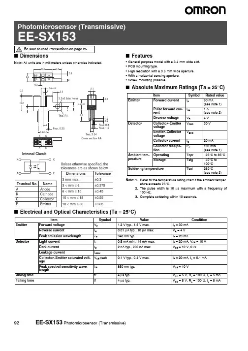
■DimensionsNote:All units are in millimeters unless otherwise indicated.■Features•General-purpose model with a 3.4-mm-wide slot.•PCB mounting type.•High resolution with a 0.5-mm-wide aperture.•With a horizontal sensing aperture.•Screw-mounting possible.■Absolute Maximum Ratings (Ta=25°C)Note:1.Refer to the temperature rating chart if the ambient temper-ature exceeds 25°C.2.The pulse width is 10 μs maximum with a frequency of100Hz.plete soldering within 10 seconds.■Electrical and Optical Characteristics (Ta = 25°C)Item Symbol Rated valueEmitter Forward current I F50 mA(see note 1)Pulse forward cur-rent I FP 1 A(see note2)Reverse voltage V R 4 V Detector Collector–EmittervoltageV CEO30 VEmitter–CollectorvoltageV ECO---Collector current I C20 mACollector dissipa-tion P C100 mW(see note 1)Ambient tem-perature Operating Topr–25°C to 85°C Storage Tstg–40°C to100°CSoldering temperature Tsol260°C(see note 3)Item Symbol Value Condition Emitter Forward voltage V F 1.2 V typ., 1.5 V max.I F = 30 mAReverse current I R0.01 μA typ., 10 μA max.V R = 4 VPeak emission wavelengthλP940 nm typ.I F = 20 mADetector Light current I L0.5 mA min., 14 mA max.I F = 20 mA, V CE = 10 V Dark current I D 2 nA typ., 200 nA max.V CE = 10 V, 0 l xLeakage current I LEAK------Collector–Emitter saturated volt-ageV CE (sat)0.1 V typ., 0.4 V max.I F = 20 mA, I L = 0.1 mAPeak spectral sensitivity wave-lengthλP850 nm typ.V CE = 10 VRising time tr 4 μs typ.V CC = 5 V, R L = 100 Ω, I L = 5 mA Falling time tf 4 μs typ.V CC = 5 V, R L = 100 Ω, I L = 5 mA Be sure to read Precautions on page25.92EE-SX153 Photomicrosensor (Transmissive)EE-SX153 Photomicrosensor (Transmissive) 93■Engineering DataDissipation Temperature RatingVoltage Characteristics (Typical)Light Current vs. Collector −Emitter Voltage Characteristics (Typical)Dark Current vs. Ambient Temperature Characteristics (Typical)Distance d (mm)Input OutputInputOutput90 %10 %(C e n t e r o f o p t i c a l a x i s )Sensing Position Characteristics (Typical)Response Time Measurement CircuitAmbient temperature Ta (°C)C o l l e c t o r d i s s i p a t i o n P C (m W )Forward voltage V F (V)F o r w a r d c u r r e n t I F (m A )Forward current I F (mA)Collector −Emitter voltage V CE (V)Ambient temperature Ta (°C)Load resistance R L (k Ω)T a = −30°C T a = 25°C T a = 70°CT a = 25°C V CE = 10 VI F = 40 mA I F = 30 mA I F = 20 mA I F = 10 mAT a = 25°CV CE = 10 V 0 l xI F = 20 mA V CE = 5 VI F = 20 mA V CE = 10 V Ta = 25°CV CC = 5 V Ta = 25°CR e s p o n s e t i m e t r , t f (μs )D a r k c u r r e n t I D (n A )I F = 50 mA Ambient temperature Ta (°C)I F P CRelative Light Current vs. Ambi-ent Temperature Characteristics (Typical)Response Time vs. Load Resist-ance Characteristics (Typical)100806040200−1.5−2.0−1.0−0.500.5 1.0 1.5 2.0120dDistance d (mm)(Center of optical axis)Sensing Position Characteristics (Typical)I F = 20 mA V CE = 10 V Ta = 25°C d100806040200−0.5−0.2500.250.50.75 1.0120。
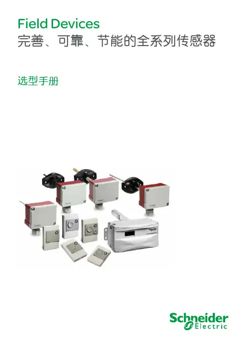
Field Devices完善、可靠、节能的全系列传感器选型手册施耐德电气在中国1987年,施耐德电气在天津成立第一家合资工厂梅兰日兰,将断路器技术带到中国,取代传统保险丝,使得中国用户用电安全性大为增强,并为断路器标准的建立作出了卓越的贡献。
90年代初,施耐德电气旗下品牌奇胜率先将开关面板带入中国,结束了中国使用灯绳开关的时代。
施耐德电气的高额投资有力地支持了中国的经济建设,并为中国客户提供了先进的产品支持和完善的技术服务,中低压电器、变频器、接触器等工业产品大量运用在中国国内的经济建设中,促进了中国工业化的进程。
目前,施耐德电气在中国共建立了77个办事处,26家工厂,6个物流中心,1个研修学院,3个研发中心,1个实验室,700多家分销商和遍布全国的销售网络。
施耐德电气中国目前员工数近22,000人。
通过与合作伙伴以及大量经销商的合作,施耐德电气为中国创造了成千上万个就业机会。
施耐德电气 能效管理平台全球能效管理专家施耐德电气为世界100多个国家提供整体解决方案,其中在能源与基础设施、工业过程控制、楼宇自动化和数据中心与网络等市场处于世界领先地位,在住宅应用领域也拥有强大的市场能力。
致力于为客户提供安全、可靠、高效的能源,施耐德电气2010年的销售额为196亿欧元,拥有超过110,000名员工。
施耐德电气助您——善用其效,尽享其能!施耐德电气善用其效 尽享其能凭借其对五大市场的深刻了解、对集团客户的悉心关爱,以及在能效管理领域的丰富经验,施耐德电气从一个优秀的产品和设备供应商逐步成长为整体解决方案提供商。
今年,施耐德电气首次集成其在建筑楼宇、IT 、安防、电力及工业过程和设备等五大领域的专业技术和经验,将其高质量的产品和解决方案融合在一个统一的架构下,通过标准的界面为各行业客户提供一个开放、透明、节能、高效的能效管理平台,为企业客户节省高达30%的投资成本和运营成本。
目 录温度传感器 (2)房间温度传感器 (2)风道温度传感器 (3)水管温度传感器 (3)室外温度传感器 (4)湿度传感器 (4)室内湿度传感器 (4)风道湿度传感器 (6)室外湿度传感器 (7)空气品质传感器 (8)CO2传感器 (8)CO传感器 (9)压力及压差传感器 (10)空气压差传感器 (10)液体压差传感器 (10)液体压力传感器 (10)数字式压力传感器(气体、液体、蒸汽、油) (11)其它传感器 (11)照度传感器 (11)防冻开关 (11)风速传感器 (11)水流开关 (11)冷凝传感器 (11)1234567891011。
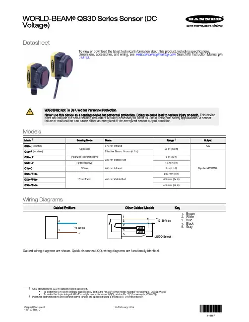
DatasheetTo view or download the latest technical information about this product, including specifications,dimensions, accessories, and wiring, see . Search for Instruction Manual p/n 119165.WARNING: Not To Be Used for Personnel ProtectionNever use this device as a sensing device for personnel protection. Doing so could lead to serious injury or death. This device does not include the self-checking redundant circuitry necessary to allow its use in personnel safety applications. A sensor failure or malfunction can cause either an energized or de-energized sensor output condition.ModelsWiring Diagrams–++10–30 V dc –2.White3.Blue4.Black5.GrayCabled wiring diagrams are shown. Quick disconnect (QD) wiring diagrams are functionally identical.suffix “W/30” to the model number (for example, QS30E W/30).•To order the 5-pin integral M12/Euro-style quick disconnect (QD), add suffix “Q” (for example, QS30EQ).2Polarized Retroreflective and Retroreflective ranges are specified using a model BRT-84 retroreflector.WORLD-BEAM ® QS30 Series Sensor (DC Voltage)Original Document 119167 Rev. C20 February 2018119167SpecificationsSupply Voltage10 V dc to 30 V dc (10% max. ripple) at less than 40 mA, exclusive of loadProtected against reverse polarity and transient voltagesOutput ResponseOpposed Mode: 5 milliseconds ON and OFFAll others: 2 millisecondsNOTE: 100 millisecond delay on power-up; outputs do not conduct during this time RepeatabilityOpposed Mode: not applicableAll others: 500 microseconds Cutoff Point ToleranceFixed-Field only: ± 5% of nominal cutoff distanceConstruction and MountingABS housing, rated IEC IP67; NEMA 6; Acrylic lens cover3 mm mounting hardware includedConnections2 m (6.5 ft) unterminated 5-wire PVC cable; 9 m (30 ft) unterminated 5-wire PVCcable ; or Integral 5-pin M12/Euro-style male quick disconnect (QD) Application Tip for the QS30LV ModelFor best sensing reliability, targets should be a minimum of 0.5m from the sensorOutput ConfigurationBipolar: One current sourcing and one current sinkingRating: 100 mA maximum each output at 25 °COff-state leakage current:NPN: less than 200 μAPNP: less than 10 μAON-state saturation voltage:NPN: less than 1.6 V at 100 mAPNP: less than 2.0 V at 100 mAProtected against false pulse on power-up and continuous overload or short circuit of outputs AdjustmentsSelectable Light/Dark Operate is achieved via the gray wire.Opposed, Retroreflective, and Polarized Retroreflective models: Light Operate - Low (0 to 3 V)*Dark Operate - High (open or 5 to 30 V)*Diffuse and Fixed-Field models:Light Operate - High (open or 5 to 30 V)*Dark Operate - Low (0 to 3 V)*Diffuse, Retroreflective, and Polarized Retroreflective mode models (only): Single-turn Sensitivity (Gain) adjustment potentiometer * Input impedance 10 kΩIndicators2 LEDs on sensor top:Large oval LED on sensor back (except emitters): Yellow on indicates the output is conducting Operating Conditions–20 °C to +70 °C (–4 °F to +158 °F)95% at +50 °C maximum relative humidity (non-condensing)Vibration and Mechanical ShockAll models meet Mil Std. 202F requirements. Method 201A (vibration: 10 Hz to 60 Hz max., double amplitude 0.06 inch, maximum acceleration 10G). Also meets IEC947-5-2 requirements: 30G 11 ms duration, half sine wave.CertificationsPendingDimensions2 x ø3.3 mm (0.125")max. torque0.7 Nm (6 in lbs)M30 x 1.5 Threadmax. torque6 Nm (53 in lbs)with included 30 mmmounting nutYellow LEDOutputIndicatorYellow and Green LEDsCabled Models QD ModelsAll measurements are listed in millimeters [inches], unless noted otherwise.Banner Engineering Corp. Limited WarrantyBanner Engineering Corp. warrants its products to be free from defects in material and workmanship for one year following the date of shipment. Banner Engineering Corp. will repair or replace, free of charge, any product of its manufacture which, at the time it is returned to the factory, is found to have been defective during the warranty period. This warranty does not cover damage or liability for misuse, abuse, or the improper application or installation of the Banner product.THIS LIMITED WARRANTY IS EXCLUSIVE AND IN LIEU OF ALL OTHER WARRANTIES WHETHER EXPRESS OR IMPLIED (INCLUDING, WITHOUT LIMITATION, ANY WARRANTY OF MERCHANTABILITY OR FITNESS FOR A PARTICULAR PURPOSE), AND WHETHER ARISING UNDER COURSE OF PERFORMANCE, COURSE OF DEALING OR TRADE USAGE.This Warranty is exclusive and limited to repair or, at the discretion of Banner Engineering Corp., replacement. IN NO EVENT SHALL BANNER ENGINEERING CORP. BE LIABLE TO BUYER OR ANY OTHER PERSON OR ENTITY FOR ANY EXTRA COSTS, EXPENSES, LOSSES, LOSS OF PROFITS, OR ANY INCIDENTAL, CONSEQUENTIAL OR SPECIAL DAMAGES RESULTING FROM ANY PRODUCT DEFECT OR FROM THE USE OR INABILITY TO USE THE PRODUCT, WHETHER ARISING IN CONTRACT OR WARRANTY, STATUTE, TORT, STRICT LIABILITY, NEGLIGENCE, OR OTHERWISE.Banner Engineering Corp. reserves the right to change, modify or improve the design of the product without assuming any obligations or liabilities relating to any product previously manufactured by Banner Engineering Corp. Any misuse, abuse, or improper application or installation of this product or use of the product for personal protection applications when the product is identified as not intended for such purposes will void the product warranty. Any modifications to this product without prior express approval by Banner Engineering Corp will void the product warranties. All specifications published in this document are subject to change; Banner reserves the right to modify product specifications or update documentation at any time. Specifications and product information in English supersede that which is provided in any other language. For the most recent version of any documentation, refer to: .WORLD-BEAM® QS30 Series Sensor (DC Voltage)© Banner Engineering Corp. All rights reserved。
U槽型光电传感器手册新款科力传感器科技(东莞)有限公司Qily Sensor Technology (Dongguan) Co.,Ltd公司简介科力传感器科技(东莞)有限公司成立于2018年,是一家专业从事工业自动化传感器系列产品及仪器仪表的研发、设计、推广应用及技术服务于一体的专业传感器企业。
公司骨干人员2008年开始专业研发生产安全光栅等传感器。
公司紧跟市场新技术及新应用,发挥自身技术优势,不断推出新产品适应市场需求。
同时重视对制造能力和质量控制能力的建设和提高,拥有专业的管理队伍、科研队伍。
科力可向客户提供各种技术先进,性能可靠,质量稳定的工业自动化产品,部分产品可根据客户的特殊要求进行定制,最大限度满足客户安全保护或其它使用要求。
公司可及时为客户提供售前、售中和售后服务。
公司客户遍及全国各主要自动化设备生产厂家,如:富士康、大族激光、美的集团、格力集团等。
公司产品出口至俄罗斯、澳大利亚、意大利、美国等国家,品质得到客户认可。
我们秉持“科技创新,力争上游”的公司发展理念,以高性价比的产品向客户提供周到的服务,并努力期待着与广大客户一起,共同开创互惠互利、共赢共荣的美好未来。
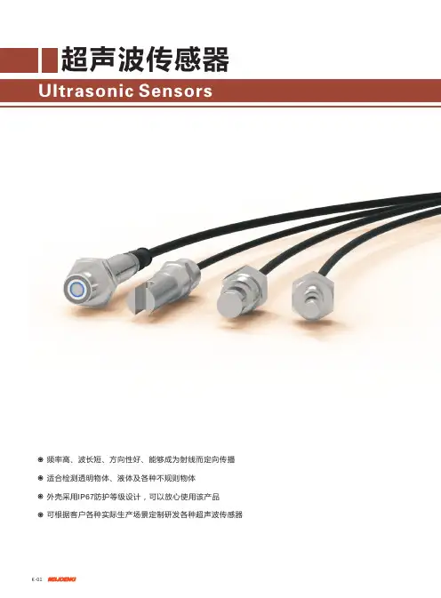
我们自主研发光电传感器专用芯片放大器 发射接收模块 逻辑处理 电源管理 高度集成 稳定可靠SMIC 65nm 工艺各个功能模块集成于一颗芯片中电流小于7mA ,芯片发热量小频率2KHz 响应,残留电压小于0.8V@100mA 负载电流三重保护输出短路保护 电源接反保护 电流过载保护工作电压DC5-30V 的超宽范围IP65工况-25℃~+55℃,5%~85%RH 环境可正常工作产品特色超小结构便于设备小型化 核心芯片技术,单面PCBA采用GaAS 红外LED(940nm) 抗强光干扰,抗强电磁干扰漂移小,焊接良率高 高可靠性,高寿命 外围电路仅3个元器件, 产品一致性高配备柔性电缆,外壳使用高精度磨具,材料采用磨砂性高档树脂超小型·电缆型PM-25 SERIESPM-K25 PM-L25 PM-F25 PM-R25 PM-U25 小型·电缆型UX-67WR SERIESUX670-WR UX671-WR UX672-WR UX674-WR小型·插件型UX-67 SERIESUX670 UX671 UX672 UX674形状插件电缆(2m 长):正面 反面技术参数类型 凹槽型NPN 型 PM-□25 UX67□(-WR) PNP 型 PM-□25PUX67□P(-WR)检测距离 5mm (槽宽) 标准检测物 1.8 x 0.8 以上不透明物体 光源(峰值发光波长) 红外发光二极管(940nm) 指示灯 入光时点亮(红色发光二极管) 电源电压DC5~30V ±10% 纹波 (p-p ) 10%以下控制输出负载电压: DC5~30V 负载电流: 50mA 以下 OFF 电源: 0.5mA 以下残留电压: 0.7V 以下(负载电流50mA 时): 0.4V 以下(负载电流5mA 时)保护回路 电源接反/输出短路/电流过载三重保护 重复定位精度 0.03mm 以下 (注*1) 响应频率 2kHz (响应时间0.5ms )(注*2) 使用环境照度 受光面照度太阳光 : 10万lux 以下环境温度范围 工作时: -25~+55℃ 保存时: -30~+80℃ (无结冰、无结露的状态) 环境湿度范围 工作时: 5~85%RH 保存时: 5~95%RH (无结冰、无结露的状态) 振动(耐久) 10~2,000Hz (峰值加速度 150m/s2);单振幅: 0.75mm X 、Y 、Z 各方向 2.5h (15min 周期 10循环)冲击(耐久) 500m/s X 、Y 、Z 各方向: 3次保护结构 IP65 IEC60529标准连接方式 导线引出型(标准导线长2m ,其它规格的线长订货时说明)质量(包装状态) 约20g外壳、盖材质 聚对苯二甲酸丁二醇酯(PBT )投、受光材质聚碳酸酯(PC) 注:*1 在槽的横向上移动了检测物体时的值。
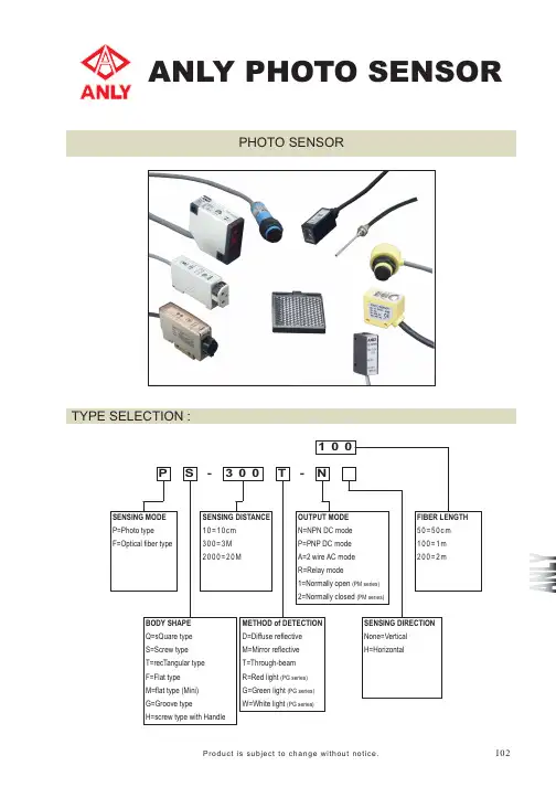
ANLY PHOTO SENSORPHOTO SENSORTYPE SELECTION :I02PS0T30--001NProduct is subject to change without notice.SENSING MODE P=Photo type F=Optical fiber typeBODY SHAPE Q=sQuare type M=flat type (Mini)G=Groove type S=Screw type T=recTangular type F=Flat type H=screw type with HandleSENSING DISTANCE 10=10cm 300=3M 2000=20MMETHOD of DETECTION D=Diffuse reflective M=Mirror reflective T=Through-beam R=Red light (PG series)G=Green light (PG series)W=White light (PG series)SENSING DIRECTION None=Vertical H=HorizontalOUTPUT MODE N=NPN DC mode P=PNP DC mode A=2 wire AC mode R=Relay mode1=Normally open (PM series)2=Normally closed (PM series)FIBER LENGTH 50=50cm 100=1m 200=2mGENERAL DATA :Switching frequency: 80Hz Switching frequency: 80Hz Switching frequency: 60Hz Switching frequency: 60Hz Switching frequency: 30Hz Switching frequency: 30HzSwitching frequency: 100Hz Switching frequency: 100Hz Switching frequency: 80Hz Switching frequency: 80HzSwitching frequency: 30HzSensing distance: 10cmDC 10 ~ 30VSensing distance: 30cmDC 10 ~ 30VSwitching frequency: 1kHzAU-F02DC 10 ~ 30VSensing distance: 3mDC 10 ~ 30VSensing distance: 20mDC 10 ~ 30VPF-300M-R seriesSensing distance: 1mAC/DC 24 ~ 240VPF-2000T-R seriesSensing distance: 3mAC/DC 24 ~ 240VPT-15D seriesSensing distance: 20mAC/DC 24 ~ 240VPT-30D seriesSensing distance: 15cmDC 10 ~ 30VPT-200M seriesSensing distance: 30cmDC 10 ~ 30VPT-200T seriesSensing distance: 2mDC 10 ~ 30VSensing distance: 2mDC 10 ~ 30VSensing distance: 5cmConjunction with AU-F01/02Fiber (ӿ1.0)Fiber (ӿ2.2 x 2)Fiber (ӿ1.0 x 2)Fiber (ӿ2.2)Fiber (ӿ1.0)Fiber (ӿ2.2) Fiber (ӿ2.2 x 2)Fiber (ӿ1.0 x 2)Sensing distance: 4cmConjunction with AU-F01/02Sensing distance: 1.2cmConjunction with AU-F01/02FS-05T series FS-15T series FH-05T seriesSensing distance: 15cmConjunction with AU-F01/02 FH-15T seriesSensing distance: 5cmConjunction with AU-F01/02Sensing distance: 15cmConjunction with AU-F01/02FS-01D series FS-04D seriesSensing distance: 1.2cmConjunction with AU-F01/02FH-01D series Sensing distance: 4cmConjunction with AU-F01/02FH-04D seriesSwitching frequency: 30HzPF-200D-R seriesSensing distance: 2mAC/DC 24 ~ 240VSwitching frequency: 30HzPF-500M-R seriesSensing distance: 5mAC/DC 24 ~ 240VSwitching frequency: 30HzPF-700M-R seriesSensing distance: 7mAC/DC 24 ~ 240VSwitching frequency: 30HzPF-1000T-R seriesSensing distance: 10mAC/DC 24 ~ 240VSwitching frequency: 100Hz Switching frequency: 100HzPM-10D seriesSensing distance: 10cmDC 10 ~ 30VSensing distance: 40cmDC 10 ~ 30VPM-40D seriesAU-F01Switching frequency: 1kHzDC 12 ~ 24VPS, PT seriesCONNECTION :PF seriesDCBrown N.O.N.C.DCDC PMseriesDCPG, PQ series NPN typePG series PNP typeDCDCGreenBlackYellowAC/DC GreenBlackYellowGreenBlackYellowTargetPM-200M series PM-200T series Sensing distance: 2m Switching frequency: 80Hz Switching frequency: 80Hz Switching frequency: 60HzDC 10 ~ 30V Sensing distance: 2m DC 10 ~ 30V PG-06 seriesSensing distance: 6mm DC 10 ~ 30VNPN typePNP typeLight sourceDiffuse reflective typeThrough-beam typeMirror reflective typeDIMENSIONS : (mm) PS series。
SL30系列槽形传感器416SL30系列槽形传感器S L 30 S e r i e s电缆式接插件式* 暗态操作,将灰线接至+(棕)亮态操作,将灰线接至-(蓝)或开路5针Euro 型接插件(所示为接插件式电缆端) •Email: sensors@417SL30系列槽形传感器SL30 系列电缆式接插件式418SL30系列槽形传感器S L 30 S e r i e s电缆式接插件式SL30型SLE30专家型接插件式系列槽形传感器 •Email: sensors@421SL10系列槽形传感器SL10 系列电缆式接插件式* 暗态操作,将灰线接至+(棕)亮态操作,将灰线接至-(蓝)或开路5针Euro 型接插件(所示为接插件式电缆端)422SL10系列槽形传感器S L 10 S e r i e s电缆式接插件式C-GAGE®SLC1系列标签检测传感器• 采用自适应数字逻辑技术(ADL),无需用户调整,传感器自动进行示教• 连续自动调整门槛值,并进行补偿• 定位精度±0.3mm• 标签最大运行速度10m/s(33'/s)• 可靠检测底带上的多种标签- 不透明底带上的透明标签- 透明底带上的透明标签- 不透明底带上的不透明标签- 透明底带上的不透明标签• 外壳坚固,槽宽1mm(0.04")注:对于含金属成分或碳素墨水成分,以及凹凸明显或带金属基片的标签,不推荐使用此种传感器424C - GAGE ®®SL C1系列标签检测传感器S L C 1 S e r i e s对于SLC1传感器:i) 9m(30')电缆的型号通过在电缆型传感器的型号后添加后缀“W/30”加以识别(如SLC1BB6 W/30)ii) QD 型需要另配接插电缆* 标签间隙3.2mm(0.125"),纸带运行速度最大10m/s 。
对于系统的实际运行速度,我们主要考虑纸带的瞬间速度,而不是平均速度。

槽型光电开关的应用和检测现在,各种光电开关在自动监测、自动控制、自动计数等生产领域得到了广泛的应用。
在实际生产维修当中,笔者根据光电开关的工作原理,利用两只万用表,对槽型光电开关的好坏进行快速判别。
现以电动绕线机上计数用的槽型光电开关为例(也有称为"凹型光电开关的),将测试方法介绍给大家。
槽型光电开关实物图见图1,内部原理图见图2。
先把万用表拨在R×100挡,两表笔分别测C、E的正、反向电阻应为无穷大,否则已损坏或性能变差。
再把黑表笔搭在C脚,红表笔搭在E脚,然后把另一只万用表拨在R×1挡,其黑表笔搭在A脚,红表笔搭在K脚,利用万用表内部电池电压使光电发射管工作,此时C、E脚的电阻值马上降为较小值。
拿掉A、K脚表笔,C、E脚电阻值马上恢复为无穷大。
如把黑表笔搭在K脚,红表笔搭在A脚,则C、E无穷大电阻值不变,即可判断光电开关基本正常。
把搭A、K脚的万用表拨到R×lO或R×100挡时,C、E脚的导通电阻值将逐步增大,这主要是随着万用表电阻挡位的增大,其电阻挡"输出"的工作电流也随着下降,使流过光电发射管的电流变小,发射红外线能力变弱,光电接收管的导通电阻也随着增大,可进一步证明光电开关正常。
需要说明:如一只采用指针式万用表,另一只采用数字式万用表,测试时应把数字式万用表接C、E脚,指针式万用表接A、K 脚。
这是由于数字式万用表的二极管挡或电阻挡只能提供微小的电流,不足以使光电开关中的发射管正常工作。
在实际应用当中,光电开关的大小和形状因使用场合、用途的不同而干差万别。
槽式光电开关通常是标准的凹字形结构,其光电发射管和接收管分别位于凹形槽的两边,并形成一光轴。
当被检测物体经过凹形槽并阻断光轴时,光电开关就产生了检测到的开关信号。
槽式光电开关安全可靠,适合检测高速变化的生产监测场所。
光电开关内部结构主要有NPN型和PNP 型两种。
一般光电开关的工作电流约5~20n1A,工作电压应低于30V,输出驱动电流则根据型号的不同而有很大的差别,大的几百毫安,小的只有几毫安。
Technical DataOriginal InstructionsRightSight M30Catalog Numbers 42AF-P2MAB1-F4, 42AF-P2MAB1-D4, 42AF-P2RHB1-G4, 42AF-E1EZB1-F4, 42AF-E1EZB1-D4, 42AF-R1MAB1-D4,42AF-R1MAB1-F4, 42AF-R1RHB1-G4, 42AF-E1UZB1-G4, 42AF-P2CHB1-A2, 42AF-R1CHB1-A2, 42AF-E1UZB1-A2, 42AF-P2SHB1-G4,42AF-R1SHB1-G4, 42AF-P2CHB1-M5, 42AF-R1CHB1-M5, 42AF-E1UZB1-M4Summary of ChangesThis publication contains the following new or updated information.This list includes substantive updates only and is not intended toreflect all changes.DescriptionThe RightSight™ M30 family of photoelectric sensors offers high-performance general-purpose sensing in a robust flexible package.They are designed for applications where simplified installation andmaintenance are required.Designed to withstand the rigors of material handling andpackaging environments, the RightSight M30 standard models canwithstand IP69K high-pressure washdowns.This family also offers a background reflection/foregroundsuppression sensing mode that allows you to use the surface of abackground (for example, a conveyor) as a reflector. The detectionof a target occurs once an object blocks the visual path betweenthe sensor and the background (for example, conveyor).Available Models•Polarized retroreflective•Transmitted beam•Background suppression•Background reflectionStatus IndicatorsTopic PageDescription1Status Indicators1Features2Specifications2Product Selection3Sensor User Interface4Wiring4Approximate Dimensions5Typical Response Curves5Accessories6Topic PageUpdated Description1Updated Available Models list1Updated Features2Updated Product Selection table and Connection OptionsImportant table that follows3Updated Figure2, Figure3, Figure4, and Figure9 titles 4 and 5Updated Figure125Orange IndicatorGreen Indicator2Rockwell Automation Publication 42AF-TD001B-EN-P - June 2020RightSight M30 Technical DataFeatures•Maximum sensing distance-Background suppression without physicaladjustments (a): 400 mm (15.7 in.) and 600 mm (23.6 in.)-Background suppression with push button teach (a): 1.2 m (3.94 ft)-Background reflection with push button teach (a): 800 mm (31.5 in.)-Polarized retroreflective:10 m (32.8 ft) with 92-125 reflector -Transmitted beam:80 m (262.5 ft)•High powered light source for ease of alignment•360° highly visible user interface helps operators verify the proper operation, regardless of the sensor installation location•Background suppression performance helps minimize false detections due to highly reflective backgrounds•Dual Auto PNP/NPN helps streamline inventory by reducing the number of catalog numbers to stock•Push button lock helps prevent unauthorized operators from changing the sensor settings•Embedded IO-Link 1.1 communications protocol•Adjustable sensing ranges and response time via IO-Link provides additional flexibility to detect targets at longer or shorter distances depending on the application requirements.•IP67 and IP69K rated enclosure.Specifications(a)All models can be taught to detect targets up to 4 m (13.1 ft.) when using IO-Link to adjustthe response timeAttribute ValueCertifications c-UL-us and CE Marked for all applicable directivesVibration 10…55 Hz, 1 mm (0.04 in.) amplitude, meets, or exceeds 60947-5-2Shock30 g (1.1 oz) with 1 ms pulse duration per IEC 60947-5-2Ambient light immunity •Direct Illumination: 20,000 lux•Indirect Illumination: 5000 lux•Sunlight immunity; 108,000 lux User Interface Status indicators Green and orange light-emitting diodes (LED)Electrical Adjustments No physical adjustment. IO-Link adjustable Operating voltage •DC models: 10...30V DC, IO-Link: 18 (30V)•AC/DC models: AC: 24…250V AC/DC: 20…250V DC Current consumption 35 mA maxSensor protection DC: Reverse polarity and short circuit; AC/DC: Reverse polarity Discrete Output Response time •DC: 1 ms•AC/DC: 15 ms max Output type •DC: Dual Auto PNP or NPN •AC/DC: EM RelayLoad current •DC: 100 mA max•AC/DC SPDT: 10…30V DC: 3 A; 31…125V DC: 200 mA;24…250V AC: 3 AIO-LinkCommunications mode COM2Cycle time, min 2 ms Process data bit length 32 bits (4 bytes)Specifications 1.1Mechanical Housing material PBT Lens material PMMA Cover material Polysulfone Reliability DataTransmitted Beam and Polarized Retroreflective AC/DC MTTFd (hours)6548788.474T10d78.76Transmitted Beam and Polarized Retroreflective DC MTTFd (hours)9310986.965T10d111.9875Transmitted Beam Emitter AC/DC MTTFd (hours)24271844.66T10d291.9285467Transmitted Beam Emitter DC MTTFd (hours)24271844.66T10d 291.9285467Environmental Enclosure type ratingIP67 and IP69K per ISO 20653 rated enclosureOperating temperature -40…+70 °C (31…158 °F) (1)(1)The sensing range for all sensing modes can be reduced up to 20% when operatedbetween -40…-25 °C (-40…-13 °F).Connection type • 2 m (6.5 ft) cable •4-pin Integral M12 QD•4-pin M12 QD on a 150 mm (5.9 in.) pigtail•4-pin mini QD on 150 mm (5.9 in.) pigtail •5-pin mini QD on 150 mm (5.9 in.) pigtailRockwell Automation Publication 42AF-TD001B-EN-P - June 20203RightSight M30 Technical DataProduct SelectionSee https:///Sensors-Switches/Photoelectric-Sensors for additional details about the operation of the RightSight M30 in IO-Link mode.Sensing Mode Operating Voltage Light SourceSensing DistanceSensitivity Adjustment Output Function Output Type Cat. No.Background Suppression10...30V DC InfraredDefault setting:10...400 mm (0...15.7 in.)No physical adjustment. IO-Link teach: 4 m (13.1 ft) (1)(1)Sensor response time can be changed up to 75 ms to achieve distance of up to 4 m (13.1 ft). A higher distance between target and high reflectivity background may be needed whenoperating the sensors at distances greater than 2 m (6.6 ft).Light and dark operate Dual autoPNP or NPN42AF-B1MAB1-D4Default setting:10...600 mm (0...23.6 in.)No physical adjustment. IO-Link teach: 4 m (13.1 ft) (1)42AF-B1MAB2-D4Default setting:10...1.2 m (0...3.9 ft)Push button teach: 3 m (9.8 ft) IO-Link teach: 4 m (13.1 ft) (1)42AF-B1MAC1-D4Background Reflection10...30V DC Infrared0...800 mm (0...31.5 in.)Push button teach: 3 m (9.8 ft) IO-Link teach: 4 m (13.1 ft) (1)Light and dark operate Dual auto PNP or NPN 42AF-N1MAC1-D4Polarized Retroreflective10...30V DCVisible red0.025...10 m (0.03...33 ft)with 92-125 reflector No adjustment (IO-Link adjustable)Light and dark operate Dual auto PNP or NPN42AF-P2MAB1-D420...250V DC 24...250V AC No adjustment Light operate SPDT EM relay 42AF-P2RHB1-G4Dark operate 42AF-P2SHB1-G4Light and dark operate42AF-P2CHB1-A2Transmitted Beam10...30V DC Infrared0...80 m (0...262 ft)No adjustment (IO-Link adjustable)Transmitted beam emitter —42AF-E1EZB1-D420...250V DC 24...250V AC42AF-E1UZB1-G410...30V DC No adjustmentLight and dark operate Dual auto PNP or NPN 42AF-R1MAB1-D420...250V DC 24...250V ACLight operate SPDT EM relay42AF-R1RHB1-G4Dark operate 42AF-R1SHB1-G4Light and dark operate42AF-R1CHB1-A2IMPORTANTConnection Options (1): The following suffixes describe the available connection options:•D4: Describes an integral 4-pin DC micro (M12) quick-disconnect for DC models.•G4: Describes a 4-pin AC micro (M12) quick-disconnect on a 150 mm (6 in.) length pigtail on AC/DC models.•F4: Describes a 4-pin DC micro (M12) quick-disconnect on a 150 mm (6 in.) length pigtail on DC models.•A2: Describes a 2 m (6.6 ft) PVC cable.•M4: Describes a 4-pin mini quick-disconnect on a 150 mm (6 in.) length pigtail. Transmitted beam emitter only.•M5: Describes a 5-pin mini quick-disconnect on a 150 mm (6 in.) length pigtail on AC/DC models. Polarized retroreflective and transmitted beam receivers only.(1)Additional connection options may be available. See the ProposalWorks™ tool for available options by sensing mode.Table 1 - Standard I/O (Auto PNP/NPN) Operating Mode IndicationColorStatus Description GreenOFF Power is off ON Power is onFlash (6 Hz)Unstable light: 0.8 X <margin<1.5X Flash (1.4 Hz)Output short circuit protection active OrangeOFF Output de-energized ONOutput energizedTable 2 - IO-Link Operating Mode IndicationColor Status Description Green OFF Power is off Flash (1 Hz)Power is onOrangeOFF Output de-energized ONOutput energized4Rockwell Automation Publication 42AF-TD001B-EN-P - June 2020RightSight M30 Technical DataSensor User InterfaceThe green status indicator can also serve as a setup alignment aid. As the sensor is adjusted, • A flashing green indicator shows that the sensor has detected a margin of 0.8 X• A flashing green indicator and steady orange output indicator shows a margin greater than 1•Steady green and orange indicators show a margin greater than 1.5. This status means that the sensor is receiving at least 1.5 times the signal strength back from the target that is required to trigger an output signal.In general, it is desirable to have a higher margin to help overcome any deteriorating environmental conditions (dust build-up on the sensor lens). When aligning the sensor, the optimum performance can be obtained if this margin indicator is illuminated with the target in place.Table 3 provides indicator status in the RUN mode, during operation. The sensor is always in run mode except when being taught.WiringThe quick-disconnect connector is shown in Figure 1. The pin numbers correspond to the male connectors on the sensor.Figure 1 - PinoutsDC ModelsFigure 2 - Polarized Retroreflective(42AF-P2MAB1-F4 and 42AF-P2MAB1-D4)Light Operate and Dark Operate (Auto PNP or NPN)Figure 3 - Transmitted Beam Receiver (42AF-R1MAB1-F4 and 42AF-R1MAB1-D4)Light Operate and Dark Operate (Auto PNP or NPN)Figure 4 - Transmitted Beam Emitter (42AF-E1EZB1-F4 and 42AF-E1EZB1-D4)Table 3 - Connection TypesDescriptionCat. No. Suffix2 m (6.56 ft) cable-A24-pin DC micro (M12) QD on 150 mm (6 in.) pigtail -F4Integral 4-pin DC micro (M12) QD-D44-pin AC micro on 150 mm (6 in.) pigtail -G44-pin mini QD on 150 mm (6 in.) pigtail -M45-pin mini QD on 150 mm (6 in.) pigtail-M5Item DescriptionLED Disable For normal operation, the white wire needs no connection.To disable the light source, connect the white wire to +V.Frequency SelectFor normal operation, the white wire needs no connection.To change the emitter operating frequency, connect the black wire to +V. This feature is supported in future firmware revisions of the Transmitted Beam Receiver.IMPORTANTFor transmitted beam emitter only:Do not connect pin 2 and pin 4 for normaloperation. Unless a change in frequency is required when working with a receiver, these two pins remain unconnected when wiring the transmitted beam emitter sensor to anArmorBlock® I/O module.4-pin Micro (M12)Brown (1)Blue (3)Black (4)White (2)+V-VLight Operate (Auto PNP/NPN)Dark Operate (Auto PNP/NPN)Brown (1)Blue (3)Black (4)White (2)+V-VLight Operate (Auto PNP/NPN)Dark Operate (Auto PNP/NPN)Brown (1)Blue (3)Black (4)White (2)+V-VFrequency Select LED DisabledRockwell Automation Publication 42AF-TD001B-EN-P - June 20205RightSight M30 Technical DataAC/DC ModelsFigure 5 - Polarized Retroreflective and Transmitted Beam Emitter Light Operate (42AF-P2RHB1-G4 and 42AF-R1RHB1-G4)Figure 6 - Dark Operate(42AF-P2SHB1-G4 and 42AF-R1SHB1-G4)Figure 7 - Polarized Retroreflective and Transmitted Beam (42AF-P2CHB1-A2 and 42AF-R1CHB1-A2)Figure 8 - Polarized Retroreflective and Transmitted Beam (42AF-P2CHB1-M5 and 42AF-R1CHB1-M5)Figure 9 - Transmitted Beam Emitter (42AF-E1UZB1-A2 and 42AF-E1UZB1-G4)Approximate DimensionsFigure 10 - Integral M12 Connector [mm (in.)]Figure 11 - M12 Pigtail and Cable Models [mm (in.)]Typical Response CurvesFigure 12 - Visible Red Polarized Retroreflective — 10 m (32.81ft) Margin CurveFigure 13 - Visible Red Polarized Retroreflective — 10 m (32.81ft) Beam PatternTable 4 - UL508 Overcurrent ProtectionConductor Size Ampere Rating of the Overcurrent Protection, MaxAWG mm 2200.525220.323240.202260.131280.080.8300.050.5Red w/Black (1)Green (3)Red (4)Red w/White (2)(-V) L2(No Connection)Light Operate (+V) L1Red w/Black (1)Green (3)Red (4)Red w/White (2)(-V) L2(No Connection)Light Operate (+V) L1(+)˜(-)˜(+)˜(-) ˜Red w/Black (1)Not Used (3)Not Used (4)Red w/White (2)(-V) L2(+V) L1Sensing Distance [m (ft)]O p e r a t i n g M a r g i n 0.01(0.03)0.1(0.33)1(3.28)10(32.81)01020304050607080(13.12)(19.68)(26.25)(32.81)(39.37)Distance [m (ft)]D i s t a n c e [c m ](6.56)6Rockwell Automation Publication 42AF-TD001B-EN-P - June 2020RightSight M30 Technical DataFigure 14 - Infrared Transmitted Beam Emitter — 80 m (262.5ft) Margin CurveFigure 15 - Infrared Transmitted Beam Emitter — 80 m (262.5ft) Beam PatternAccessoriesFigure 16 - 30 mm (1.2 in.) Right Angle Mounting BracketFigure 17 - 18 mm (0.7 in.) Swivel/Tilt Mounting BracketCat. No. 60-2421Cat. No. 60-2439IMPORTANTFor polarized retroreflective sensors only: For optimal detection performance, when highly reflective targets pass between the emitter and the reflector, we recommend that you always install the rubber washer that is provided with the polarized sensor.(0.33)(3.28)(32.81)(328.08)Sensing Distance [m (ft)]O p e r a t i n g M a r g in(13.12)(19.68)(26.25)(32.81)(39.37)Distance [m (ft)]D i s t a n c e [c m ](6.56)Cat. No. 60-2649Cat. No. 60-2681DescriptionCat. No.4-pin DC micro, 2 m (6.5 ft) cordset 889D-F4AC-218 mm (0.7 in.) straight bracket 60-265618 mm (0.7 in.) right angle bracket60-265730 mm (1.2 in.) stainless steel mounting bracket 60-242130 mm (1.2 in.) swivel/tilt bracket 60-243918 mm (0.7 in.) swivel/tilt bracket60-2649Extended 18 mm (0.7 in.) swivel/tilt bracket 60-268176 mm (3 in.) diameter reflector 92-3947 mm (1.85 in.) diameter reflector 92-4784 mm (3.3 in.) diameter reflector92-12518 mm (0.7 in.) base mount, U-shaped protective bracket 60-BAF-US 18 mm (0.7 in.) base mount bracket, stainless steel 60-BAF-BM 30 mm (1.2 in.) nose mount bracket, stainless steel60-BAF-SM Aperture, 5 x 17 mm (0.2 x 0.67 in.) vertical slot, stainless steel 60-AAF1-VS Aperture, 5 x 12 mm (0.2 x 0.47 in.) horizontal slot, stainless steel 60-AAF1-HS Aperture, 2.5 x 12 mm (0.1 x 0.47 in.) horizontal slot, stainless steel 60-AAF2-HS Aperture, 5 mm (0.2 in.) diameter, stainless steel 60-AAF1-DS Aperture, 2.5 mm (0.1 in.) diameter, stainless steel 60-AAF2-DS U-shaped protective bracket60-BAF-US 18 mm (0.7 in.) base mount bracket, stainless steel 60-BAF-BM 30 mm (1.2 in.) nose mount bracket, stainless steel60-BAF-SM Aperture, 5 x 17 mm (0.2 x 0.67 in.) vertical slot, stainless steel 60-AAF1-VS Aperture, 5 x 12 mm (0.2 x 0.47 in.) horizontal slot, stainless steel 60-AAF1-HS Aperture, 2.5 x 12 mm (0.1 x 0.47 in.) horizontal slot, stainless steel 60-AAF2-HS Aperture, 5 mm (0.2 in.) diameter, stainless steel 60-AAF1-DS Aperture, 2.5 mm (0.1 in.) diameter, stainless steel60-AAF2-DSRockwell Automation Publication 42AF-TD001B-EN-P - June 20207RightSight M30 Technical DataFigure 18 - AperturesFigure 19 - Cat. No. 60-BAF-US 18 mm (0.7 in.) Mounting BracketFigure 20 - Cat. No. 60-BAF-SM 30 mm (1.2 in.) Bracket SideFigure 21 - Cat. No. 60-BAF-BM 18 mm (0.7 in.) Bracket BackCat. No. 60-AAF1-VS 5x17 mm (0.2x0.67 in.)Vertical SlotCat. No. 60-AAF1-HS 5x12 mm (0.2x0.47 in.) Horizontal SlotCat. No. 60-AAF2-HS 2.5x12 mm (0.1x0.47 in.)Horizontal SlotCat. No. 60-AAF1-DS 5 mm (0.2 in.) DiameterCat. No. 60-AAF2-DS 2.5 mm (0.1 in.)DiameterØØ4.5018.49 (0.73)(0.33)12.7 (0.50)33.02 (1.30)6.98(0.27)2 x 1.84 (0.07)9.73(0.38)2 x Ø 4.5 (0.18)12.7(0.50)4 x 4.57(0.18)6.35(0.25)22.2(0.87)22.86 (0.90)Ø 30.15 (1.19)3.17(0.12) Ref19.05 (0.75)44.45 ± 0.25(1.75 ± 0.01)0.79(0.03) Ref90°2 x 82°R 2.29(0.09)2 x 0.77 (0.03)45.72 (1.80)2 x Ø 3.83 (0.15)2 x 1.75 (0.06)17.78(0.70)30.48 (1.20)3.17(0.12) Ref2 x 0.79(0.31)15.16(0.60)90°2 x 82°R 2.29(0.09)Ø 18.49(0.73)8.89 (0.35)9.27 (0.36)6.98(0.27)8.25(0.32)8.89(0.35)19.05 (0.75)4 x R 4.57 (0.18)35.56 (1.40)30.48(1.20)0.79(0.03) RefPublication 42AF-TD001B-EN-P - June 2020Supersedes Publication 42AF-TD001A-EN-P - January 2019Copyright © 2020 Rockwell Automation, Inc. All rights reserved. Printed in the U.S.A.Rockwell Automation SupportUse these resources to access support information.Documentation FeedbackYour comments help us serve your documentation needs better. If you have any suggestions on how to improve our content, complete the form at rok.auto/docfeedback .Waste Electrical and Electronic Equipment (WEEE)Technical Support Center Find help with how-to videos, FAQs, chat, user forums, and product notification updates.rok.auto/support KnowledgebaseAccess Knowledgebase articles.rok.auto/knowledgebase Local Technical Support Phone Numbers Locate the telephone number for your country.rok.auto/phonesupport Literature LibraryFind installation instructions, manuals, brochures, and technical data publications.rok.auto/literature Product Compatibility and Download Center (PCDC)Get help determining how products interact, check features and capabilities, and find associated firmware.rok.auto/pcdcAt the end of life, this equipment should be collected separately from any unsorted municipal waste.Rockwell Automation maintains current product environmental information on its website at rok.auto/pec .Allen-Bradley, ArmorBlock, expanding human possibility, ProposalWorks, RightSight, Rockwell Automation, and Rockwell Software are trademarks of Rockwell Automation, Inc.Trademarks not belonging to Rockwell Automation are property of their respective companies.Rockwell Otomasyon Ticaret A.Ş. Kar Plaza İş Merkezi E Blok Kat:6 34752, İçerenkÖy, İstanbul, Tel: +90 (216) 5698400 EEE YÖnetmeliğine Uygundur。
明治液位传感器说明书一、概述XX液位传感器采用带不锈钢隔离膜的扩散硅压阻式压力传感器作为信号测量元件,把与液位深度成正比的液体静压力准确测量出来,并经过专业信号调理电路转换成标准4-20mA电流或RS485信号输出,建立起输出信号与液体深度的线性对应关系,实现对液体深度的精确测量。
产品精度高,体积小,使用方便,直接投入液体中,即可测量出变送器末端到液面的液位高度。
XX液位传感器DATA-51系列广泛地应用于城市供排水、污水处理、水池、油池油罐、水文地质、水库、河道和海洋等领域二、工作原理水位计采用的传感器是以单品硅为基体,采用先进的离子注入工艺和微机械加工工艺,制成了具有惠斯顿电桥和精密力学结构的硅敏感元件。
传感器所处位置的水压通过接口作用在硅敏感元件上,实现了所加压力与输出信号的线性转换,经激光修调的厚膜电阻网络补偿了敏感元件的温度性能。
三、性能指标型号:DATA-51系列测量介质:液体(对不锈钢壳体无腐蚀)量程:0~7,10,20,35,70,100m输出信号:4-20Ma/RS485;供电电源:12~28V DC(4-20mA输出)5~28V DC(RS485输出)4-20mA型水位计负载电阻(Q):RL<(U-8)/0.02(U为电源电压)RS485型水位计温度测量范围:-10℃~80℃(功能可选)精度等级:土0.2%FS;环境温度:-10℃~80℃存储温度:-40℃~80℃过载能力:150%FS稳定性能:土0.05%FS/年;土0.1%FS/年零点温度系数:士0.01%FS/C满度温度系数:土0.02%FS/℃防护等级:IP68结构材料:外壳:不锈钢316L密封圈:氣橡胶传感器外壳:不锈钢316L 膜片:不锈钢316L电缆:中7.2mm 聚氨酯专用电缆(配套2米,超出部分按长度加价)。
SICK槽型传感器:型号丰富,功能强大槽型传感器采用对射式设计,发射器和接收器安装于同一外壳内,因此对准工作不再费时。
由于检测精度高,且发射的光束高度集中,槽型传感器能够检测出非常微弱的光线衰减。
SICK槽型传感器具有安装简单、对环境光抗扰度高以及多种叉宽选项等优势,应用领域包括传送带上的标签及零部件检测等。
优势•发射器和接收器位于同一外壳内,所需安装时间极短•提供多种叉宽、叉深和检测技术(红外LED、红色LED、激光和超声波)选项,可以满足各种需求•激光和红色光源型号传感器的光点高度可视,因此调校非常简单•开关频率高,性能可靠•对环境光具有高抗扰性,保证了检测的可靠性•采用铝质外壳,可满足一般工业条件的需求SICK 槽型传感器采用对射式设计,其发射器和接收器安装于同一个外壳内,因此对准工作不再费时。
SICK 槽型传感器有两种工作原理。
即时运行感器能够检测微弱的光吸收差异。
应用领域• 标签识别• 物体计数和定位• 过程控制收的超声波就越多。
这类传感器甚至可以检测贴在透明衬板材料上的透明标签。
应用领域• 标签识别• 双板检测• 黏性表面检测WF next详细技术资料特性机械/电气参数限定值,具有反极性保护。
在短路保护网路中运行时最大值为8 A 。
2) 不可以超出工作电压V S 的允许范围值。
3) 空载。
4) 亮/暗比为1:1。
5) 带阻抗负载时的信号传输时间。
6) 参考电压50 V DC 。
7)取决于叉宽。
环境参数特定参数工业传感器槽型传感器WF next 订货信息WF2•叉宽:2 mmWF5•叉宽:5 mmWF15•叉宽:15 mm最小检测物体。
WF30•叉宽:30 mm最小检测物体。
WF nextWF50•叉宽:50 mm1)最小检测物体。
WF80•叉宽:80 mmWF120•叉宽:120 mm工业传感器槽型传感器WF next外形尺寸图mmmmABCC1WF2 2 42/59/95 14 5(0.08) (1.65/2.32/3.74)(0.55) (0.20) WF5 5 42/59/95 14 6.5 (0.20) (1.65/2.32/3.74) (0.55) (0.20)WF15 15 42/59/95 27 5 (0.59) (1.65/2.32/3.74) (1.06) (0.20)WF30 30 42/59/95 42 5(1.18) (1.65/2.32/3.74) (1.65) (0.20)WF50 50 42/59/95 51 16(1.97) (1.65/2.32/3.74) (2.01) (0.63)WF80 8042/59/958116(3.15) (1.65/2.32/3.74) (3.19) (0.63)WF120 120 42/59/95 121 16(4.72)(1.65/2.32/3.74)(4.76)(0.63)调校WF next调校:“+”/“–”按钮WF next 调校:自学习① 光轴② 安装孔,Ø 4.2 mm ③ 仅限WF50/80/120④ 功能信号指示灯(黄色),开关输出⑤ 功能指示灯(红色)⑥ “+” /“–”按钮和功能按钮WF nextM8,4针插头L+Q PMQ N推荐附件插头和电缆M8,4针插头连接方式与示意图工业传感器槽型传感器WF next通过“+”/“–”按钮设置开关阈值 (WFxx-B410)12通过自学习设置开关阈值(WFxx-B416)1 2113 6Q。