eDCAP-625A PT测量及切换装置 使用说明书
- 格式:pdf
- 大小:1.42 MB
- 文档页数:27

US: 1-866-764-5454 CAN: 1-800-265-0502 Copyright 2022 Eaton3392C2CEDS factory sealed manual motor starting switches and enclosuresCl. I, Div. 1 & 2, Groups B A , C, D Cl. II, Div. 1, Groups E, F, G Cl. II, Div. 2, Groups F, G Cl. IIINEMA 3, 7B A CD, 9EFGExplosionproof Dust-ignitionproof RaintightWet LocationsEDSC2199EDSC2299Applications:Factory sealed enclosures are installed in a rigid metallic conduit system for surface mounting adjacent to or remote from equipment being controlled, and are used:• To prevent arcing of enclosed device from causing ignition of a specific hazardous atmosphere or atmospheres external to the enclosure• In industrial areas, such as chemical plants, oil and gas refineries, paint and varnish manufacturing plants, gasoline bulk loading terminals, grain elevators, grain processing industries, coal processing or handling areas, or metal handling or finishing areas where atmosphere may contain hazardous gases and/or dust• In non-hazardous areas where sturdy, durable enclosures are required• In conjunction with magnetic starters or contactors for remote control of motors Manual motor starting switch enclosures are used:• For manual starting of small AC or DC motors• To provide manual starting and stopping and, in the case of units with heaters, motor running protectionFeatures:Factory sealed devices have many distinct advantages:• Reduce installation problems • Eliminate external seals • Lower installation costs • Improve safety• Mounting lugs and taper tapped hubs with integral bushings• Large machine screws for fastening covers to bodies• Lockout hole for padlock having 1/4” hasp is provided• Close tolerances in machining of wide, mating flanges and journalled shafts and bearings produce flametightness of enclosure joints• Dead end (EDS) or through feed (EDSC) hubs – 3/4” or 1” sizesCertifications and compliances:N EC/CEC:• Class I, Divisions 1 & 2, Groups B A , C, D • Class II, Division 1, Groups E, F, G • Class II, Division 2, Groups F, G • Class III UL standard:• UL1203CSA standard:• C22.2 No. 30Environmental ratings:• NEMA/EEMAC 3, 7B A CD, 9EFGStandard materials:• B odies – Feraloy iron alloy (U.S.); copper-free aluminum (Canada)• Shafts and bushings – stainless steel • Sealing enclosures – copper-free aluminumStandard finishes:• Feraloy iron alloy – electrogalvanized and aluminum acrylic paint• Copper-free aluminum – natural • Type 6/6 nylon – black • Stainless steel – naturalDimensions B (in inches):Side viewSingle-gangSurfacecovers have same length and width as single- and two-gang bodies.A Seals must be installed within 1/” of each conduitopening in Division 1.B Dimensions are approximate, not for constructionpurposes.Options:Description Suffix • For use in Group B hazardousareas ..................................................GB A • Copper-free aluminum bodies andcovers ...................................................SA For single- and two-gang unitsHub sizehi3/"7/13/Front viewTwo-gang US: 1-866-764-5454 CAN: 1-800-265-0502 Copyright 2022 Eaton3402C2EDS factory sealed manual motor starting switches and enclosuresCl. I, Div. 1 & 2, Groups B C , C, D Cl. II, Div. 1, Groups E, F, G Cl. II, Div. 2, Groups F, G Cl. IIINEMA 3, 7B C CD, 9EFGExplosionproof Dust-ignitionproof Raintight Wet LocationsC Add GB suffix. Seals must be installed within 1/” of each conduit opening for Group B usage.Ordering information:Allen-Bradley①Includes one interchangeable heater. Select heater from the table below individual listings and use symbol number as second section of the catalog number. Example: EDS2199-P5. Insert symbol '0' (zero) to omit heater.These heaters are for motors rated 40°C continuously. For motors rated 50°C or 55°C, multiply full load motor current by 0.9 and use this value to select heaters. Symbol '0' (zero) must be used to indicate heater omitted.With Allen-Bradley Bulletin 600 switchesMaximum horsepower ratingsNo. of poles115-230 VAC115-230 VDCCat. #11 A B BUL 600 TOX4With General Electric switchesMaximum horsepower ratingsNo. of poles115-230 VAC115 VDC230 VDCCat. #1110.25GE CR101 Y No. of poles Hub sizeCat. # Dead endCat. # Through feedSingle-gang3/"1"EDS32100 ①EDSC32100 ①No. of poles Hub sizeCat. # Dead endCat. # Through feedSingle-gang3/"1"EDS32094 ①EDSC32094 ①Heater tables:Max. motor full load amperageEaton'sCrouse-Hinds symbol numberMax. motor full load amperageEaton'sCrouse-Hinds symbol number0.17P1 2.92P222.58P21General ElectricMax. motor full load amperageEaton'sCrouse-Hinds symbol numberMax. motor full load amperageEaton'sCrouse-Hinds symbol number0.48G2 3.27G233.01G22 US: 1-866-764-5454 CAN: 1-800-265-0502 Copyright 2022 Eaton3412CEDS factory sealed manual motor starting switches and enclosuresCl. I, Div. 1 & 2, Groups B D , C, D Cl. II, Div. 1, Groups E, F, G Cl. II, Div. 2, Groups F, G Cl. IIINEMA 3, 7B D CD, 9EFGExplosionproof Dust-ignitionproof Raintight Wet LocationsD Add GB suffix. Seals must be installed within 1/” of each conduit opening for Group B usage.Ordering information (continued):Cutler-Hammer①Includes one interchangeable heater. Select heater from the table below individual listings and use symbol number as second section of the catalog number. Example: EDS2199-P5. Insert symbol '0' (zero) to omit heater.These heaters are for motors rated 40°C continuously. For motors rated 50°C or 55°C, multiply full load motor current by 0.9 and use this value to select heaters. Symbol '0' (zero) must be used to indicate heater omitted.With Cutler-Hammer switchesMaximum horsepower ratingsNo. of poles120-240 VAC32 VDC120 VDC240 VDC Cat. #110.250.250.25WEST MST01No. of poles Hub sizeCat. # Dead endCat. # Through feedSingle-gang3/"1"EDS32102 ①EDSC32102 ①Heater tables (continued):Max. motor full load amperageEaton'sCrouse-Hinds symbol numberMax. motor full load amperageEaton'sCrouse-Hinds symbol number0.43W1 2.95W21。

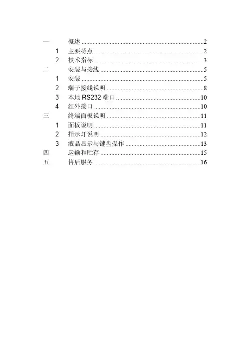
eDCAP-615A PT保护测控装置使用说明书(V01-CH-20130820)紫光测控有限公司UNISPLENDOUR M&C CO. , LTD.目录1 概述 (1)2装置主要功能配置 (1)3装置硬件资源配置 (2)4主要技术指标 (3)4.1 额定参数 (3)4.2 环境条件 (3)4.3 功率消耗 (3)4.4 热稳定性 (3)4.5 测控技术指标 (3)4.6 保护技术指标 (4)4.7 触点容量 (4)4.8 绝缘性能 (4)4.9 抗干扰能力 (5)5装置原理 (6)5.1 装置的构成 (6)5.2 保护原理说明 (6)6菜单及数据表格说明 (9)6.1 实时数据表 (9)6.2保护参数表 (10)6.3 通信数据表格 (13)6.4系统参数表 (15)6.5模拟量校准表 (19)7操作方法 (20)8装置结构及尺寸 (20)9装置原理接线图 (22)10箱后端子接线图 (23)11 概述eDCAP-615A PT 保护测控装置适用于PT 柜的保护及测控。
eDCAP-615A PT 保护测控装置支持IEC61850站控层通讯协议,支持通过GOOSE 网络发布和订阅变电站事件。
2 装置主要功能配置23 装置硬件资源配置34 主要技术指标4.1 额定参数交流电压额定值(Un):线电压:100V ,380V ;相电压:57.7V ,220V 电源频率额定值: 50Hz直流电源额定值: 220V ,110V4.2 环境条件环境温度:工作:温度范围 -10~+55℃。
贮存:温度范围 -25~+70℃,在极限值下不施加激励量,装置不出现不可逆变化,温度恢复后,装置能正常工作。
大气压力:80~110kPa (相对海拔高度2km 及以下)相对湿度:最湿月的月平均最大相对湿度为90%,同时该月的月平均最低温度为25℃,且表面无凝露。
最高温度为40℃时,平均最大相对湿度不大于50%。
4.3 功率消耗交流电压回路:不大于0.5VA/相(额定电压下)直流回路:每个保护箱不大于10W (静态)或15W (动作)4.4 热稳定性长期运行 2In ,1.5Un4.5 测控技术指标(1)交流工频输入量 a) 标称值电压:100V ,380V ;频率:50 Hz 。

T OMAHAWK ™625OPERATORʼS MANUALIM10020January, 2012Safety Depends on YouLincoln arc welding and cutting equipment is designed and built with safety in mind. However,your overall safety can be increased by proper installation ... and thoughtful operation on your part. DO NO T INSTALL,O PERATE O R REPAIR THIS EQUIPMENT WITHO UT READ-ING THIS MANUAL AND THE SAFETY PRECAUTIO NS CO N-TAINED THRO UGHO UT.And,most importantly, think beforeyou act and be careful.NOTESvfor selecting a QUALITY product by Lincoln Electric. We want you to take pride in operating this Lincoln Electric Company product ••• as much pride as we have in bringing this product to you!Read this Operators Manual completely before attempting to use this equipment. Save this manual and keep it handy for quick reference. Pay particular attention to the safety instructions we have provided for your protection.The level of seriousness to be applied to each is explained below:HIGH FREQUENCY INTERFERENCE PROTECTIONThe TOMAHAWK™ 625 employs a touch start mech-anism for arc initiation which eliminates high frequen-cy emissions from the machine as compared with spark gap and solid state type high frequency genera-tors. Keep in mind, though, that these machines may be used in an environment where other high frequen-cy generating machines are operating. By taking the following steps, high frequency interference into the TOMAHAWK™ 625 can be minimized(1)Make sure the power supply chassis is connectedto a good earth ground. The work terminal ground does NOT ground the machine frame.(2)Keep the work clamp isolated from other workclamps that have high frequency.(3)If the work clamp cannot be isolated, then keepthe clamp as far as possible from other work clamp connections.(4)When the machine is enclosed in a metal building,several good earth driven electrical grounds around the periphery of the building are recom-mended.Failure to observe these recommended installation procedures may cause improper function of the TOM-AHAWK™ 625 or possibly even damage to the control system or power supply components.INPUT ELECTRICAL CONNECTIONS The TOMAHAWK™ 625 is rated for 208VAC and 230VAC input voltage. Before installing the machine, check that input supply voltage, phase, and frequency are the same as the machine's voltage, phase, and frequency as specified on the machine's rating plate.• The TOMAHAWK™ 625 should be connected only by a qualified electrician. Installation should be made in accordance with local codes.For use on engine drives, keep in mind the above input draw restrictions and the following precaution. The TOMAHAWK™ 625 can be operated on engine driven generators as long as the 230 volt auxiliary meets the following conditions:• The AC waveform peak voltage is below 400 volts.• The AC waveform frequency is between 45 and 65 Hz.• The RMS voltage of the AC waveform is always greater than 208VAC.USER RESPONSIBILITYBecause design, fabrication, erection and cutting vari-ables affect the results obtained in applying this type of information, the serviceability of a product or struc-ture is the responsibility of the user. Variation such as plate chemistry, plate surface condition (oil, scale), plate thickness, preheat, quench, gas type, gas flow rate and equipment may produce results different than those expected. Some adjustments to procedures may be necessary to compensate for unique individ-ual conditions. Test all procedures duplicating actual field conditions.DESIGN FEATURES AND ADVANTAGESThe TOMAHAWK™ 625 design makes plasma cutting uncomplicated. This list of design features and advan-tages will help you understand the machine's total capabilities so that you can get maximum use from your machine.- Light weight and portable design for industrial use. - Continuous control, 10 - 40 amps.- Reliable touch start mechanism for plasma arc initi-ation.- Rapid arc restrike for fast cutting of expanded metal. - Input over voltage protection.- Bright 3.0 second timed pilot arc.- Purge section on output dial.- Air regulator and pressure gage included.- Internal water separator included.- Parts-in-Place mechanism to detect proper installa-tion of consumables and torch.- Preflow/Postflow timing. Preflow is eliminated if arc is re-initiated in Postflow.- Thermostatic Protection.- Solid state over-current protection.- Unique electrode and nozzle design for optimum cooling and long life.CUTTING CAPABILITYThe TOMAHAWK™ 625 is rated at 40 amps, at 35% duty cycle on a 10 minute basis. If the duty cycle is exceeded, a thermal protector will shut off the output of the machine until it cools to the normal operating temperature.Figure B.1 shows the cut capacity of the TOMA-HAWK™ 625 when cutting mild steel. (The graph plots cut thickness vs. torch travel speed with a torch standoff of 0.15".) CONSUMABLE LIFEThe expected life for the TOMAHAWK™ 625's elec-trode under normal operating conditions is approxi-mately 1000 starts/cuts. An erosion of .060" is typical for end of electrode life, however, the electrode life may last longer. A green and erratic arc will indicate definite electrode failure and the electrode should be replaced immediately.It is recommended that consumables be replaced in complete sets. (Example: Electrode and Nozzle). This will maximize the performance of the TOMAHAWK™625 system.Figure B.1 TOMAHAWK 625LIMITATIONSDo not exceed output current and duty cycle rating of machine. Do not use the TOMAHAWK™ 625 for pipe thawing.If the arc turns off while cutting using low input volt-age, that is below 208V, lower the air pressure by adjusting the regulator knob.When using with the Outback 180, gouging is not rec-ommended.Turn the machine's ON/OFF POWER SWITCH to the OFF position.• Connect the air supply to the machine.• Turn the main power on and the machine power switch to the ON position.- The fan will start.- The pre-charge circuit will operate for 3 seconds,then the green "Power" LED will illuminate.• Attach the work lead clamp to the workpiece before cutting.• Set the output current control knob to maximum position for higher cutting speed and less dross for-mation. Reduce the current, if desired to reduce the kerf (cut) width, heat affected zone, or travel speed as required.Note:If the circuit breaker trips while cutting at high-er amperages - reduce the cutting amperage on the unit, or provide an input circuit with higher current capacity.• Rotate the output knob into the purge zone to check or set the gas pressure. Pull the pressure regulator cap out and turn it to set the pressure.- Adjust the gas regulator for 75-80 PSI (0.50-0.55MPa).- Turn the output knob out of the purge zone.- The gas will immediately turn off. The pressure gage may show an increase in pressure after the air turns off but this is normal. Do NOT reset the pressure while the air is NOT flowing.PROCEDURE RECOMMENDATIONSWhen properly used, plasma arc cutting is a very eco-nomical process. Improper use will result in a very high operating cost.General - In All Cases• Follow safety precautions as printed throughout thisoperating manual and on the machine.• If piercing is required, slowly lower the torch at anangle of about 30° to blow the dross away from the torch tip and slowly rotate the torch to a ver-tical position as the arc becomes deeper. This process will blow a lot of molten metal and dross. Be careful! Blow the dross away from the torch, the operator and any flammable objects.• The nozzle should not be dragged on the metal surface. A drag spacer is provided to maintain a consistant touch height. Refer to Touch Parts Configurations in this Section.• Where possible, start the cut from the edge of thework piece.• Keep moving! A steady speed is necessary. Donot pause.• Replace the nozzle when the orifice exit is eroded away or oval shaped.• After the problem is found, or if there is nothing apparently wrong, reset the machine by turning the power switch OFF and then ON again. (It is possi-ble for electrical noise to trip the safety circuit on rare occasions. This should not be a regular occur-rence.)• If the machine does not reset or continues to trip,consult the Troubleshooting Section.• Use the proper cutting procedures referred to in Procedure Recommendations.PILOT ARC DISCUSSIONThe TOMAHAWK™ 625 has a smooth, continuous pilot arc. The pilot arc is only a means of transferring the arc to the workpiece for cutting. Repeated pilot arc starts, in rapid succession, is not recommended as these starts will generally reduce consumable life.Occasionally, the pilot arc may sputter or start inter-mittently. This is aggravated when the consumables are worn or the air pressure is too high. Always keep in mind that the pilot arc is designed to transfer the arc to the workpiece and not for numerous starts without cutting.The TOMAHAWK™ 625 does not utilize high frequen-cy starting. When the pilot arc is started, a slight impulse will be felt in the torch handle. This occur-rence is normal and is the mechanism which starts the plasma arc. This impulse can also be used to help troubleshoot a "no start" condition.Suggestions for Extra Utility from the TOMAHAWK™ 625 System:1. Occasionally an oxide layer may form over the tip of the electrode, creating an insulating barrier between the electrode and nozzle. This will result in the tripping of the TOMAHAWK™ 625's safety circuit. When this happens turn the power off,remove the nozzle and electrode and use the elec-trode to rub against the inside bottom surface of the nozzle. This will help remove any oxide buildup. Replace the nozzle, turn on the power and continue cutting. If the safety circuit continues to trip after cleaning the consumables, then replace them with a new set. Do not continue to try and cut with excessively worn consumables as this can cause damage to the torch head and will degrade cut quality. Do not allow torch cable or body to contact hot surface.2. To improve consumable life, here are some sug-gestions that may be useful:• Make sure the air supply to the TOMAHAWK™625 is clean and free of oil. Use several extra in line filters if necessary.• Minimize dross buildup on the nozzle tip by starting the cut from the edge of the plate when possible.• Pierce cutting should be done only when nec-essary. If piercing, angle torch about 30° from the plane perpendicular to the work piece,transfer the arc, then bring the torch perpendic-ular to the work and begin parallel movement.• Reduce the number of pilot arc starts without transferring to the work.• Reduce the pilot arc time before transferring to the work.• Set air pressure to recommended setting. A higher or lower pressure will cause turbulence in the plasma arc, eroding the orifice of the nozzle tip.• Use only Lincoln consumable parts. These parts are patented and using any other replace-ment consumables may cause damage to the torch or reduce cut quality.TORCH PART CONFIGURATIONSThere are different torch configurations depending onthe cutting or gouging application.Standard Cutting Setup:In the Standard Cutting configuration the nozzle isdesigned not to touch the work piece. The advantageof this cutting method is good visibility of the arc.However it requires a steady hand to avoid touchingthe nozzle to the work piece which will cause prema-ture nozzle wear and a jagged cut. An optional dragspacer can be attached to the retaining cap to main-tain a consistent arc height.Contact Cutting Setup:Contact Cutting uses special expendable parts thatallow the torch to touch the work piece. The advan-tage of contact cutting is that the torch can touch thework piece, steadily dragging it across the surface.The disadvantage of contact cutting is the plasma arcis not as visible as with a standard torch set-up. Sincethis machine cuts at 40 amps or less it uses the directcontact torch configuration which allows a special noz-zle to come in contact with the work piece.Gouging Setup:If gouging metal and not cutting completely through the part is required, a special gouging nozzle is used in conjunction with a gouge shield to protect the noz-zle from molten metal blow back.Refer to the torch parts decal located on your machine or the parts pages at the back of this manual for the specific part numbers required for each of these setups.ALWAYS USE GENUINE LINCO LN ELECTRIC ELECTRO DES, NO ZZLES, AND EXPENDABLE PARTS FO R THE BEST CUTTING PERFO R-MANCE.GENERAL OPTIONS /ACCESSORIESThe following options/accessories are available for your Tomahawk Plasma cutter from your local Lincoln Distributor.K2377-1-Small Canvas CoverProtect your machine when not in use. Made from attractive red canvas that is flame retardant, mildew resistant and water repellent. It includes a convenient side pocket to hold the plasma torch.K2886-1- Plasma Circle Cutting KitFor cutting circles from 3” to 33” in diameter (77mm to 838mm).TORCHESThe following replacement torch is available:K2847-1 LC40 Handheld Plasma Torch 20' (6m) EXPENDABLE PARTSRefer to the torch parts decal located on your machine or the parts pages at the back of this manual for the specific part numbers required for each of the avail-able setups.This Troubleshooting Guide is provided to help you locate and repair possible machine malfunctions. Simply follow the three-step procedure listed below.Step 1.LOCATE PROBLEM (SYMPTOM).Look under the column labeled “PROBLEM (SYMPTOMS)”. This column describes possible symptoms that the machine may exhibit. Find the listing that best describes the symptom that the machine is exhibiting. Step 2.POSSIBLE CAUSE.The second column labeled “POSSIBLE CAUSE” lists the obvious external possibili-ties that may contribute to the machine symptom.Step 3.RECOMMENDED COURSE OF ACTIONThis column provides a course of action for the Possible Cause, generally it states to contact you local Lincoln Authorized Field Service Facility.If you do not understand or are unable to perform the Recommended Course of Action safely, contact you local Lincoln Authorized Field Service Facility.STATUS BOARD INDICATORSJapaneseChineseKoreanArabicREAD AND UNDERSTAND THE MANUFACTURER’S INSTRUCTION FOR THIS EQUIPMENT AND THE CONSUMABLES TO BE USED AND FOLLOW YOUR EMPLOYER’S SAFETY PRACTICES.SE RECOMIENDA LEER Y ENTENDER LAS INSTRUCCIONES DEL FABRICANTE PARA EL USO DE ESTE EQUIPO Y LOS CONSUMIBLES QUE VA A UTILIZAR, SIGA LAS MEDIDAS DE SEGURIDAD DE SU SUPERVISOR.LISEZ ET COMPRENEZ LES INSTRUCTIONS DU FABRICANT EN CE QUI REGARDE CET EQUIPMENT ET LES PRODUITS A ETRE EMPLOYES ET SUIVEZ LES PROCEDURES DE SECURITE DE VOTRE EMPLOYEUR.LESEN SIE UND BEFOLGEN SIE DIE BETRIEBSANLEITUNG DER ANLAGE UND DEN ELEKTRO-DENEINSATZ DES HERSTELLERS. DIE UNFALLVERHÜTUNGSVORSCHRIFTEN DES ARBEITGEBERS SIND EBENFALLS ZU BEACHTEN.JapaneseChineseKoreanArabicLEIA E COMPREENDA AS INSTRUÇÕES DO FABRICANTE PARA ESTE EQUIPAMENTO E AS PARTES DE USO, E SIGA AS PRÁTICAS DE SEGURANÇA DO EMPREGADOR.• Sales and Service through Subsidiaries and Distributors Worldwide •Cleveland, Ohio 44117-1199 U.S.A. TEL: 216.481.8100 FAX: 216.486.1751 WEB SITE: 。

1.序言及安全2.简介3.正面面板4.电源5.显示6.工作模式7.使用指南8.帮助9.隐含设置值及开机状况10.RS23211.T625的使用12.保险丝13.清洗14.规格15.产品安全数据1.序言及安全1.1电池T625使用一组2Ah镍镉充电电池。
新电池处于放电状态,使用前必须充电24小时。
电池可能不能达到额定容量。
1.2工作安全性该产品是根据Bicotest子元器件。
公司。
1.3安全预防措施使用Bicotest T600FS600V的带电电缆。
T625仅适用容量为2Ah的0o C时不可充电。
T625主机符合IEC10102.简介2.1T625概述T625是一种时域反射仪器,也可称回波检测仪或电缆雷达,提供电缆故障的可视性指示。
发射脉冲在电缆故障点产生反射。
发射脉冲和反射脉冲均显示于屏幕中。
障脉冲的起始点,故障点的距离将显示于屏幕中。
可确定故障的类型。
注:电缆必须包含两根导线或一根导线及屏蔽。
2.2典型波形(1)开路/高阻抗串联故障注:正反射(向上)(2)短路/低阻抗并联故障注:负反射(向下)T625可用于:a)检测一组线对b)一组好线对和一组有故障线对的对比c)在一组好线对和一组有故障线对的差值中,号(如连接点、电线规格改变点或绝缘点)障。
2.3电源T625可由一组8通过直流电插座提供外接直流电源。
T625将自动关机。
2.4主要特征图1为T625正面面板图形13.正面面板3.1控制键5分(见第7章).时,T625将发出蜂鸣声。
背景灯1秒钟,背景灯将熄灭;背景灯开通54使用。
光标光标移动较慢,返回全距离范围显示。
300m或4。
介电值用于设置检测线对的速度参数。
亦可作数字键距离范围T625在有效距上下移动工作模式为工作模式为L1波形移动。
振幅T625将在有效增益范围内递变。
脉冲宽度脉冲宽度在宽和窄之间变化。
距离范围为25米时不可用。
存储T625回放12接口算机中。
帮助工作模式3.2插座2孔,4mm 2孔,4mm插座,用于连接第二个检测线对。
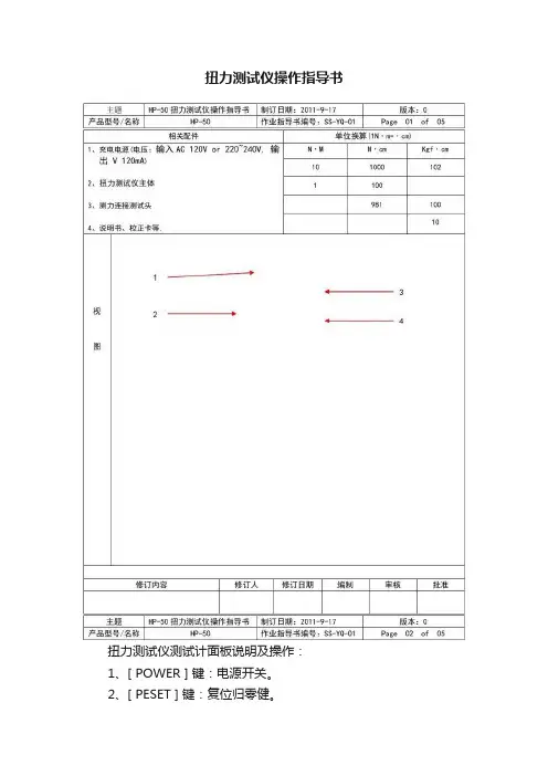
扭力测试仪操作指导书扭力测试仪测试计面板说明及操作:1、[ POWER ] 键:电源开关。
2、[ PESET ] 键:复位归零健。
3、显示屏4、[ ZERO ADJ ]调零旋钮5、[ UNIT ] 键:测量单位转换键,按此键设置测量单位,可以活动按钮,:。
6、[ MODE ] 键:测量模式键,按此键选择[ PEAK]峰值、[ TRACK ] 跟随值。
7、安全固定框8、固定旋钮二、功能设置:报警值设置:当扭力达到上限扭矩时,机器会发出用蜂鸣声提示。
HP-50 扭力测试仪扭力范围:0至 / 0~充电时间为8小时;电充足时连接使用时间可达30小时。
电压:输入AC 120V or 220~240V, 输出 V 120mA5、此扭力测试仪精确度为±%以内.XXXXXXXXXXXXXX公司扭力测试仪操作指导书在使用扭力测试仪前,先确定测试仪电量是否足够,再打开电源开关。
若电量不足时,将自动关机,需充足电(充电时间3—5小时)。
要固定扭力测试仪,可使用固定旋钮;如图1所示。
调节调零旋钮来做扭力测试仪测试前数值调零。
(调零时,模式开关必须处于TRACK档上。
)根据测试需要,选择单位切换开关来调整力矩单位(后续按Kgf·cm作为测量单位)。
选择需要的测量模式,通过测量模式开关选定跟随值(TRACK)或峰值(PEAK)。
当需要测量最大峰值时,设定模式开关至峰值(PEAK)档,测量出来的数值会保留15秒以上。
假如按一下复位按钮,数据会自动清除归零。
根据不同的被测物,来选择匹配的带安全框的测试配件。
当使用扭力测试仪测量电动螺丝刀或风批等工具时,选用合适的测试配件安置在测试传感头上。
(可为不同的被测物定制合适的治具)。
测量完成后,关闭电源,取下附件和待测物。
测力连接测试头使用:利用其可以测量除风批以外的其它工具的扭力。
比如:转轴、手表链、灯座、电批等扭力及校准扭力工具等。
除用高精度转接器或螺纹杆外,亦可自制转接器将不同尺寸的扭力工具头连接到连接座作测量。

互感器综合特性测试仪。
在您初次使用该仪器前,请您详细地阅读本使用说明书,将可帮助您熟练地使用本仪器。
我们的宗旨是不断地改进和完善公司的产品,因此您所使用的仪器可能与使用说明书有少许的差别。
如果有改动的话,我们会用附页方式告知,敬请谅解!您有不清楚之处,请与公司售后服务部联络,我们定会满足您的要求。
由于输入输出端子、测试柱等均有可能带电压,您在插拔测试线、电源插座时,会产生电火花,小心电击,避免触电危险,注意人身安全!安全要求请阅读下列安全注意事项,以免人身伤害,并防止本产品或与其相连接的任何其它产品受到损坏。
为了避免可能发生的危险,本产品只可在规定的X围内使用。
只有合格的技术人员才可执行维修。
—防止火灾或人身伤害使用适当的电源线。
只可使用本产品专用、并且符合本产品规格的电源线。
正确地连接和断开。
当测试导线与带电端子连接时,请勿随意连接或断开测试导线。
产品接地。
本产品除通过电源线接地导线接地外,产品外壳的接地柱必须接地。
为了防止电击,接地导体必须与地面相连。
在与本产品输入或输出终端连接前,应确保本产品已正确接地。
注意所有终端的额定值。
为了防止火灾或电击危险,请注意本产品的所有额定值和标记。
在对本产品进行连接之前,请阅读本产品使用说明书,以便进一步了解有关额定值的信息。
请勿在无仪器盖板时操作。
如盖板或面板已卸下,请勿操作本产品。
使用适当的保险丝。
只可使用符合本产品规定类型和额定值的保险丝。
避免接触裸露电路和带电金属。
产品有电时,请勿触摸裸露的接点和部位。
在有可疑的故障时,请勿操作。
如怀疑本产品有损坏,请本公司维修人员进行检查,切勿继续操作。
请勿在潮湿环境下操作。
请勿在易爆环境中操作。
保持产品表面清洁和干燥。
-安全术语警告:警告字句指出可能造成人身伤亡的状况或做法。
小心:小心字句指出可能造成本产品或其它财产损坏的状况或做法。
-=全自动型测试仪=-仅需进行简单的数字设定:设定最高测试电压、最大电流装置将自动从零逐步升压。

cdm625a中文说明书摘要:一、前言二、产品概述三、产品规格四、操作步骤1.准备工作2.安装与拆卸3.使用说明4.维护与保养五、注意事项六、售后服务正文:【前言】cdm625a 是一款高品质的中文说明书,为用户提供了详细的产品使用信息。
本说明书旨在帮助用户更好地了解和使用产品,确保安全、高效地操作。
【产品概述】cdm625a 是一款功能强大的设备,适用于各种场合。
本设备采用了先进的技术,具有出色的性能和稳定性,能够满足用户多样化的需求。
【产品规格】本产品具体规格如下:1.尺寸:长x 宽x 高=20cm x 15cm x 10cm2.重量:约1kg3.电压:220V4.功率:50W5.频率:50Hz【操作步骤】【准备工作】在使用cdm625a 之前,请确保阅读本说明书,并按照以下要求进行准备工作:1.确保设备已从包装箱中取出。
2.检查设备外观是否有损坏或划痕。
3.确保电源线已连接好。
4.确保设备所处环境温度适宜。
【安装与拆卸】1.将设备放置在稳固的平面上,确保设备稳定。
2.拆卸设备时,请按照相反的顺序进行,避免对设备造成损坏。
【使用说明】1.打开设备电源,根据需要调整工作模式。
2.按照操作界面提示进行操作。
3.在使用过程中,请勿堵塞设备通风口,以免影响设备散热。
【维护与保养】1.定期检查设备,确保设备正常运行。
2.保持设备清洁,避免灰尘积累。
3.使用柔软的干布擦拭设备表面。
4.避免在潮湿环境中使用设备。
【注意事项】1.请勿将设备暴露在雨水中或潮湿环境中。
2.请勿将设备暴露在高温或阳光直射的环境中。
3.请勿在设备上放置重物或对设备进行撞击。
4.请勿自行拆卸或改装设备。
【售后服务】如有任何关于cdm625a 的问题,请随时联系售后服务中心。
SENSATA SENSORS AND SWITCHES FOR AIRCONDITIONING AND REFRIGERATIONIn the increasingly demanding world of HVAC systems, high efficiency, compliance and connectivity is a must. To meet these demands, more and technologically advanced sensors are needed. That’s what Sensata delivers. Our application experts work with engineers one-on-one, every day, to help you increase energy efficiency and system reliability, achieve regulatory compliance, incorporate environmentally-friendly refrigerants and satisfy your appetite for new features and greater connectivity.When you collaborate with Sensata, you gain our 30 years of experience as a leader in commercial HVAC systems. And with engineering and support specialists deployed around the world, you can count on Sensata to be there for you, when and where you need us.Residential Air Conditioning Light Commercial Air ConditioningVariable Refrigerant Flow Systems (VRF)Bus/Train Air ConditioningRooftops and Chillers Control UnitsBeverage Dispensing & Cooling Supermarket Refrigeration (Showcase,Vertical Display cases, etc.)Transport Refrigeration (Reefer Trucks, Cooled Cargo Containers, etc)APPLICATION OVERVIEWOUR DEVICES ENABLE MORE EFFICIENT, COMPLIANT, CONNECTED SYSTEMS.Pressure switches:20PS & PS80 - automatic reset25PS - automatic reset29PS - manual resetPressure sensors:116CP/117CP - ceramic capacitive 0 – 16 bar range2CP5 &35CP - ceramic capacitive 0 – 60 bar range81/82CP - tif tube port 0 – 60 bar range2HMP - oil filled mems, hermetic 0 – 70 bar range112CP - integrated P+T 0 – 60 bar rangePTE7000 - hermetic 0 – 600 bar rangeP99x - silicon capacitive 0 – 25 mBar rangeP1K/P1J - piezo-resistive 0 - 25mBar rangeThermostats:1NT and 3NTFor the PS80, 25 PS, 2CP5 & 81/82CP, and 3NT: ATEX compliantoptions are available.Motor Protectors:HM Motor Protector seriesPhenolic Motor Protector series (3/4”)Sensata solutions for Air Conditioning and Refrigeration provide:• Precise refrigerant pressure measurement and control• Pressure sensing for efficient variable speed control & VRF systems• Robust sensors and switches suitable for mobile refrigerationapplications• Integrated pressure and temperature sensors for reduced components• Hermetic options for demanding HVAC environments• Solutions available suitable for a variety of natural refrigerants (CO2,ammonia, hydrocarbons)• Long term reliabilityFeatures and benefits of Sensata’s products :• Suitable for CO2, ammonia, R290, R1234YF, R32, etc.• Industry leading accuracy over wide operating ranges• Fully stainless steel options available• Broad operating temp. range (- 40°C to +135°C)• Hermetic and case isolated options available• Outstanding EMC/ESD performance• Overvoltage and reverse polarity protection• Atex certified pressure switches and sensors• Pressure ranges of 0 – 70 bar, 0 – 600 bar, 0 – 25mBar• Flexibility with ports, connectors and mounting optionsSensata Technologies is one of the world’s leading suppliers of sensing, electrical protection, control and power management solutions with operations and business centers in twelve countries. Sensata’s products improve safety, efficiency and comfort for millions of people every day in automotive, appliance, aircraft, industrial, military, heavy vehicle, heating, air-conditioning and ventilation, data, telecommunications, recreational vehicle and marine applications.For more information, please visit Sensata’s website.PRODUCT OVERVIEW。
综合测试仪设备操作说明书仪器名称综合测试仪功能电气测试文件编号仪器型号厂商版本一、面板介绍:1. POWER :电源开关2. LCD 显示屏:显示测试画面B HOST 接口:用于拷贝资料4. 蜂鸣器口:用于发出OK 与NG 声响5.功能键:不同显示画面对应不同功能6. 调用测试文件功能键:用于调取测试资料7.MEAS 键:按此键可直接进入测试界面8.SUTEP 键:按此键可直接进入测量设置界面9.SYSTEM 键:系统设置界面 10.数值键:用于向仪器输入数据11.ESC 键:退出功能12.BACKSPACE 键:用于删除输入数值最后一个键 13.CAL 键:可选择对扫描测试开路、短路校准 14.KEYLOCK 键:开、解锁键 15.DC BIAS 键:用于允许和禁止直流偏置输出16.RESET 键:复位键,当变压器扫描测试进行时,按下此键即停止扫描17.TRIGGER 键:触发按键,当仪器触发方式设定为MAN (手动)模式时,按此键可触发仪器测试 18.连接扫描盒前端口:用于仪器连接扫描盒进持扫描测量19.ENTEN 键:用于终止输入数据输入20.光标键:进行光标移动选择所需项目21.机壳接地端:该接线端于仪器机壳相连。
用于保护或屏蔽接地连接22.功能键:复合功能键。
当变压器扫描显示页面,插上U 盘按此键,可选择拷全屏或保存测试数至U 盘;当变压器设置页面,可快速的切换变压器测试页面核准审核制作日期4321567 8 910110 120130140 150 160 170 18192021 22仪器名称综合测试仪功能电气测试文件编号仪器型号厂商版本二、操作说明:1.仪器、扫描盒、治具的连接如下图:23.连接扫描盒前端口:用于扫描盒连接仪器24.扫描盒:由仪器控制其扫描测量 25.脚踏板开关: 26.综合测试治具27.SCANNER :控制端口,用专用电缆线将扫描盒SCANNER 接口与仪器SCANNER 接口相连接28.专用电缆线:用于仪器与扫描盒的连接 29.电源线:用于接通220V/50HZ 的电压 30.SCANNER 接口:通过SCANNER 接口控制变压器扫描盒2.仪器的开机:接通220V/50HZ 电源后,按下如图“1”电源开关按键后再按MEAS 键进入变压器测试界面。
PMAC625/PMAC625H 三相交流智能数显仪表说明书Installation & Operation ManualV2.0安全注意事项危险和警告⏹本设备只能由专业人士进行安装。
⏹对于因不遵守本手册的说明而引起的故障,厂家将不承担任何责任。
触电、燃烧或爆炸的危险⏹设备只能由取得资格的工作人员才能进行安装和维护。
⏹对设备进行任何操作前,应隔离电压输入和电源供应,并且短路所有电流互感器的二次绕组。
⏹要用一个合适的电压检测设备来确认电压已切断。
⏹在将设备通电前,应将所有的机械部件,门和盖子恢复原位。
⏹设备在使用中应提供正确的额定电压。
不注意这些预防措施可能会引起严重伤害。
目 录一、PMAC625/PMAC625H技术规格参数 (5)二、PMAC625/PMAC625H外形和安装尺寸 (7)三、PMAC625低压三相交流智能数显仪表订货说明 (8)四、PMAC625H高压三相交流智能数显仪表订货说明 (9)五.PMAC25低压三相交流智能数显仪表型号列表 (10)六.PMAC625H高压三相交流智能数显仪表型号列表 (12)五、PMAC625/PMAC625H显示及按键操作说明 (13)六、通讯协议 (19)七、附录 (24)1. PMAC625/PMAC625H端子定义 (24)2. PMAC625/PMAC625H典型接线图 (25)概 述PMAC625/PMAC625H三相交流智能数显仪表, 广泛适用于各行业供配电场所、能源管理、自动化以及智能化网络监控系统等。
PMAC625系列仪表适用于220/380V低压系统,PMAC625H系列仪表适用于6KV(含6KV)以上高压系统。
产品提供电压、电流、有功功率、无功功率、功率因数、频率、有功电度、无功电度等电参数的组合测量,扩展两路外部有源开关量输入与控制开关动作的两路继电器报警输出功能,通过RS485/MODBUS总线通讯,对仪表进行组网管理,实现自动控制。
安全性能综合测试仪使用手册1. 确保电源和连接- 请确保测试仪的电源线能够正常连接到电源插座,并且电压稳定。
- 确保测试仪的所有连接线和接口都正确插入,不要插反。
2. 开机和关机- 打开测试仪的电源开关,并确认显示屏上出现正常的显示。
- 在使用完毕后,请先关闭测试仪的测试程序,然后再关闭电源开关。
3. 操作步骤- 根据测试要求,选择对应的测试功能,并设置相关参数。
- 确保被测试物品已经准备就绪,并按照正确的测试步骤进行操作。
- 在测试过程中,遵循正确的安全操作流程,并严禁超负荷操作。
4. 故障排除- 如果测试仪出现任何异常情况,请立即停止使用,并查看故障排除部分的说明。
如果无法解决,请联系生产厂家或经销商进行维修。
5. 使用注意事项- 请勿将测试仪放置在潮湿、易燃或腐蚀性环境中。
- 请勿将测试仪暴露在阳光直射或高温环境中。
- 在使用过程中,严禁将任何金属物品或液体物质进入测试仪内部。
谢谢您阅读本手册,希望它能帮助您正确、安全地使用安全性能综合测试仪。
如有任何疑问或建议,请随时联系我们。
祝您工作顺利!当使用安全性能综合测试仪进行测试时,为了确保测试的准确性和稳定性,需要注意以下几点:6. 安全防护- 在测试仪运行时,应确保测试区域内没有其他人员进入,以免发生意外。
- 在测试过程中,切勿触摸测试仪上的高压或高温部件,避免触电或烫伤。
- 如果测试中需要使用安全防护设备,如手套、防护眼镜等,务必全程佩戴。
7. 温度和湿度- 在使用测试仪前,应确保测试环境的温度和湿度符合规定的工作条件,以免影响测试结果的准确性。
- 在使用过程中,避免将测试仪放置在潮湿或温度过高的环境中,以免影响仪器的稳定性。
8. 定期检查和维护- 对于长时间未使用的测试仪,应进行相应的检查和维护,确保仪器处于良好的工作状态。
- 定期对测试仪进行清洁、校准和维护,以确保测试结果的准确性和稳定性。
9. 安全存放- 在使用完毕后,将测试仪存放在干燥、通风的地方,远离潮湿、高温和直射阳光。