博士(BOSCH)连接器样本
- 格式:pdf
- 大小:3.44 MB
- 文档页数:52

Diesel Einspritzausrüstung / Electronic Diesel EquipmentThe last edition is validEDC Steuergerät Typ: MS6.2Ein / Ausgangsbeschreibung: Y281 V00 302 ECU type: MS6.2description of inputs and outputs:Y281 V00 302Table of ContentsTABLE OF CONTENTS2 1. LIST OF PLUG CONNECTORS3 1.1 Engine Wiring Harness41.2 Body Wiring Harness52. EXPLANATION OF TERMS USED63. GENERAL INFORMATION74. DESCRIPTION OF SINGLE INPUTS AND OUTPUTS8Diesel Einspritzausrüstung / Electronic Diesel EquipmentThe last edition is validEDC Steuergerät Typ: MS6.2Ein / Ausgangsbeschreibung: Y281 V00 302 ECU type: MS6.2description of inputs and outputs:Y281 V00 3021. List of Plug ConnectorsTwo 35 Pin Plugs as in connector offer drawing A 928 000 198E.1 928 401 987 Plug at the Engine Wiring Harness: Code No. 81 928 401 985 Plug at the Body Wiring Harness: Code No. 6Diesel Einspritzausrüstung / Electronic Diesel EquipmentThe last edition is validEDC Steuergerät Typ: MS6.2Ein / Ausgangsbeschreibung: Y281 V00 302 ECU type: MS6.2description of inputs and outputs:Y281 V00 3021.1 Engine Wiring HarnessPin Abbreviation Connected Vehicle Component Page A01DZI1Increment Speed Sensor, Sensor Signal8 A02DZS1Segment Speed Sensor, Sensor Signal9 A03BAT+Supply Terminal for Supplementary Equipment10 A04LTF0Air Temperature Sensor, Sensor Ground11 A05WTF0Water Temperature Sensor, Sensor Ground12 A06KTF0Fuel Temperature Sensor, Sensor Ground13 A07VTD1Variable Turbo Speed Sensor, Sensor Signal14 A08ARS-0EGR Positioner15 A09MBR-0Engine Brake Power Ouput, Switched Output16 A10OTF1Oil Temperature Sensor, Sensor Signal17 A11KTF1Fuel Temperature Sensor, Sensor Signal18 A12LDF1Boost Pressure Sensor, Sensor Signal19 A13DZI0Increment Speed Sensor, Sensor Ground20 A14DZS0Segment Speed Sensor, Sensor Ground21 A15na22 A16GND-A Analog Ground for OTF, ODG and VTD23 A17LDF0Boost Pressure Sensor, Sensor Ground24 A18BAT+Supply Terminal for Supplementary Equipment25 A19ODG1Oil Pressure Sensor, Sensor Signal26 A20ODG2Oil Pressure, Sensor supply27 A21LTF1Air Temperature Sensor, Sensor Signal28 A22WTF1Water Temperature Sensor, Sensor Signal29 A23LDF2Boost Pressure Sensor, Sensor Supply30 A24MG1-1Injection Valve Highside31 A25MG2-1Injection Valve Highside32 A26MV2-0Injection Valve Lowside33 A27MV4-0Injection Valve Lowside34 A28MV6-0Injection Valve Lowside35 A29MV8-0Injection Valve Lowside36 A30RL5-0Reserve lowside switch37 A31LDS-0Electro-pneum. transducer for boost pressure, Switched Output38 A32MV7-0Injection Valve Lowside39 A33MV5-0Injection Valve Lowside40 A34MV3-0Injection Valve Lowside41 A35MV1-0Injection Valve Lowside42Diesel Einspritzausrüstung / Electronic Diesel EquipmentThe last edition is validEDC Steuergerät Typ: MS6.2Ein / Ausgangsbeschreibung: Y281 V00 302 ECU type: MS6.2description of inputs and outputs:Y281 V00 3021.2 Body Wiring HarnessPin Abbreviation Connected Vehicle Component Page B01BAT-Battery-43 B02BAT-Battery -44 B03BAT+Battery +45 B04BAT+Battery +46 B05TDS A Speed Sensor Signal, Software Generated Output47 B06DIA-B Bidirectional Output for Diagnosis48 B07MPS-A Multiplex Signal49 B08AN31Reserve Analog Input50 B09LKS-0Intercooler Bypass Actuator, Switched Output51 B10KSH-0Cold Start Heater 1, Switched Output52 B11CANL CAN-Interface53 B12CANH CAN-Interface54 B13ISO-K ISO-K-Interface55 B14MBR-E Engine Brake Signal, Input56 B15K15-E Terminal 15 (Switched +U bat),57 B16PWG2Accelerator Pedal, Sensor Supply58 B17LGS-E Low Idle Position Switch Signal, Input59 B18RL4-0Reserve Lowside Switch60 B19AN11Reserve Analog Input61 B20KUP-E Clutch Switch Signal, Input62 B21DE08-E Reserve Digital Input63 B22HBR-E Parking Brake Signal, Input64 B23PWG1Accelerator Pedal Signal, Sensor Signal65 B24na66 B25GND-0Sensor Ground67 B26BRE-E Brake Switch Signal, Input68 B27HRL-0Main Relay, Switched Output69 B28MDB1Torque Limitation Signal, Input70 B29FGG1Vehicle Speed Sensor, Sensor Signal71 B30PB1-E Pulse Width Modulated Signal 1, Input72 B31DE04-E Reserve Digital Input73 B32FGR-Cruise Control Activator, Decelerate, Input74 B33FGR-A/W Cruise Control Activator, Off/Resume, Input75 B34FGR+Cruise Control Activator, Set/Accelerate, Input76 B35PWG0Accelerator Pedal Signal, Sensor Ground77Diesel Einspritzausrüstung / Electronic Diesel EquipmentThe last edition is validEDC Steuergerät Typ: MS6.2Ein / Ausgangsbeschreibung: Y281 V00 302 ECU type: MS6.2description of inputs and outputs:Y281 V00 3022. Explanation of Terms usedC EMC:Input- or output capacitancef:FrequencyF abs:Absolute deviationI o:Output currentI os Short circuit currentI olim :Threshold for overcurrent detectionna:not applicatednc:not connectedR pu:Pull-up resistanceR pd:Pull-down ResistanceR in:Input resistanceR ON:ON-resistanceR gen:Generator internal resistanceR sht:Resistance of short circuitR term Termination resistort:Signal timeT:Periodt r:Rise timet f:Fall timeτ:Time constantU o:Output voltageU bat Battery voltageU cla:Clamping voltageU L:Switching level for logic LOWU H:Switching level for logic HIGHU hys:HysteresisvoltageU D : DifferentialU CM : Common mode voltageU CH : Voltage at CAN HU CL :Voltage at CAN LU ingr :Basic switching levelU inta:Amplitude, at which threshold adaption beginsU LL:Open circuit voltageU R:Reference voltage of the ADC, U R = 5V ± 5%U reon Voltage for main relay onU reoff Voltage for main relay offU in:Input voltageU off:Cut off levelDiesel Einspritzausrüstung / Electronic Diesel EquipmentThe last edition is validEDC Steuergerät Typ: MS6.2Ein / Ausgangsbeschreibung: Y281 V00 302 ECU type: MS6.2description of inputs and outputs:Y281 V00 3023. General InformationAny connection to the ECU is only authorized in accordance withBOSCH-wiring documentation and the peripherals belonging to the system.All Inputs and Outputs are protected against short-circuit to U bat+ or U bat- ,unless otherwise stated.More than one short-circuit simultaneously can damage the ECU due toincreased power dissipation.The following ground pins are not protected against short-circuit to U bat+ :A4, A5, A6, A13, A14, A16, A17, B25, B35.Connector-pins B3, B4, A3, A18 are not protected against short-circuit to ground.The ECU is protected against battery reversal, if the main relay ispowered by the ECU itself.The specifications for the time constant are valid for a generatorinternal resistance of 0Ω.Supply of the ECUU bat+ via terminal named BAT+U bat- via terminal named BAT-Current directions:Positive currents flow into the unit.Negative currents flow out of the unit.Reference ground for all voltages is terminal B25.Diesel Einspritzausrüstung / Electronic Diesel EquipmentThe last edition is validEDC Steuergerät Typ: MS6.2Ein / Ausgangsbeschreibung: Y281 V00 302 ECU type: MS6.2description of inputs and outputs:Y281 V00 3024. Description of Single In- and OutputsConnector pin: A01Frequency input: DZI1A13Reference ground:Functionality:adaptive threshold input for inductive sensorsParameter Conditions Min.typ.Max Dim.Cto Case, GND1nF EMCR in4,84,95,0kΩU0,10,30,4V LLτR Gen = 0 Ω0,015ms UValid Range100V int/T U in × 0,5 V2050%U1,4V intaU0,20,30,4V ingrU-0,100,1V offDiesel Einspritzausrüstung / Electronic Diesel EquipmentThe last edition is validEDC Steuergerät Typ: MS6.2Ein / Ausgangsbeschreibung: Y281 V00 302 ECU type: MS6.2description of inputs and outputs:Y281 V00 302Connector pin: A02Frequency input: DZS1A14Reference ground:Functionality:adaptive threshold input for inductive sensorsParameter Conditions Min.typ.Max Dim.Cto Case, GND1nF EMCR in5,55,65,7kΩU0,20,30,4V LLτR Gen = 0 Ω0,015ms Valid Range100V Uint/T U in × 0,5 V2050%U1,4V intaU0,20,30,4V ingrU-0,100,1V offDiesel Einspritzausrüstung / Electronic Diesel EquipmentThe last edition is validEDC Steuergerät Typ: MS6.2Ein / Ausgangsbeschreibung: Y281 V00 302 ECU type: MS6.2description of inputs and outputs:Y281 V00 302Connector pin: A03Supply: BAT+Reference ground: B01, B02Functionality:supply of external loads, internally connected to B03, B04Diesel Einspritzausrüstung / Electronic Diesel EquipmentThe last edition is validEDC Steuergerät Typ: MS6.2Ein / Ausgangsbeschreibung: Y281 V00 302 ECU type: MS6.2description of inputs and outputs:Y281 V00 302Connector pin:A04Ground terminal:LTF0Reference ground:-Functionality:reference ground for sensor, internally connected to B1, B2Diesel Einspritzausrüstung / Electronic Diesel EquipmentThe last edition is validEDC Steuergerät Typ: MS6.2Ein / Ausgangsbeschreibung: Y281 V00 302 ECU type: MS6.2description of inputs and outputs:Y281 V00 302Connector pin:A05Ground terminal:WTF0Reference ground:-Functionality:Reference ground for sensor, internally connected to B01, B02Diesel Einspritzausrüstung / Electronic Diesel EquipmentThe last edition is validEDC Steuergerät Typ: MS6.2Ein / Ausgangsbeschreibung: Y281 V00 302 ECU type: MS6.2description of inputs and outputs:Y281 V00 302Connector pin:A06Ground terminal:KTF0Reference ground:-Functionality:Reference ground for sensor, internally connected to B01, B02Diesel Einspritzausrüstung / Electronic Diesel EquipmentThe last edition is validEDC Steuergerät Typ: MS6.2Ein / Ausgangsbeschreibung: Y281 V00 302 ECU type: MS6.2description of inputs and outputs:Y281 V00 302Connector pin: A07Frequency input: VTD1A16Reference ground:Functionality:adaptive threshold input for inductive sensorsParameter Conditions Min.typ.Max Dim.to Case, GND1nF CEMCR in10kΩU0,52V LLτR Gen = 0 Ω6µs UValid Range30V in× 0,5 V625% t/T Uin1,4V UintaUdependent of sensor0,681,05V ingrdependent of sensor-0,100,1V UoffDiesel Einspritzausrüstung / Electronic Diesel EquipmentThe last edition is validEDC Steuergerät Typ: MS6.2Ein / Ausgangsbeschreibung: Y281 V00 302 ECU type: MS6.2description of inputs and outputs:Y281 V00 302Connector pin: A08Power Output: ARS 0Reference ground: B01, B02Functionality: lowside switch to U bat- , freewheeling diode to U bat+ .Parameter Conditions Min.typ.Max Dim. CEMCto Case, GND0,911,1nFUoat free-wheel condition at 1A ind. Load U bat++ 2VIoPower Output OFFPower Output ON 12mAAI olim2,23,2A RonECU-CASE-Temp.= 80 C0,850ÏFor dissipation reasons it is necessary to limit the RMS-sum of the currents that sink into the following terminals:B18, A30, A08, A09 .The root mean square sum of those currents must not pass a limit of 5W/RON.The following equation must be complied with:∑ (I n out2) Ø 5W / RonDiesel Einspritzausrüstung / Electronic Diesel EquipmentThe last edition is validEDC Steuergerät Typ: MS6.2Ein / Ausgangsbeschreibung: Y281 V00 302 ECU type: MS6.2description of inputs and outputs:Y281 V00 302Connector pin: A09Power Output: MBR 0Reference ground: B01, B02Functionality:lowside switch to U bat- , freewheeling diode to U bat+ .Parameter Conditions Min.typ.Max Dim. CEMCto Case, GND0,911,1nFUoat free-wheel condition at 1A ind. Load U bat++2VIoPower Output OFFPower Output ON 12mAAI olim2,23,2A RonECU-CASE-Temp.= 80 C0,850ÏFor dissipation reasons it is necessary to limit the RMS-sum of the currents that sink into the following terminals:B18, A30, A08, A09 .The root mean square sum of those currents must not pass a limit of 5W/RON.The following equation must be complied with:∑ (I n out2) Ø 5W / RonDiesel Einspritzausrüstung / Electronic Diesel EquipmentThe last edition is validEDC Steuergerät Typ: MS6.2Ein / Ausgangsbeschreibung: Y281 V00 302 ECU type: MS6.2description of inputs and outputs:Y281 V00 302Connector pin: A10Analog input: OTF 1Reference ground:A06Functionality:analog sensor inputParameter Conditions Min.typ.Max Dim.CEMCto Case, GND0,911,1nFR in R puR pd 0,7612,1kΩkΩULL UR- 0,4UR- 0,3UR- 0,2VτR Gen = 0 Ω0,5ms UinEvaluation Range0,3U R- 0,3V F abs Measurement Precision U in /U R from InputPin to Digital Value1,5%Diesel Einspritzausrüstung / Electronic Diesel EquipmentThe last edition is validEDC Steuergerät Typ: MS6.2Ein / Ausgangsbeschreibung: Y281 V00 302 ECU type: MS6.2description of inputs and outputs:Y281 V00 302Connector pin: A11Analog input: KTF 1Reference ground:A06Functionality:analog sensor inputParameter Conditions Min.typ.Max Dim.CEMCto Case, GND0,911,1nFR in R puR pd 0,7612,1kΩkΩULLU R - 0,4U R - 0,3U R - 0,2V τR Gen = 0 Ω0,5msUinEvaluation Range0,3U R - 0,3V F abs Measurement Precision U i n /U R from InputPin to Digital Value1,5%Diesel Einspritzausrüstung / Electronic Diesel EquipmentThe last edition is validEDC Steuergerät Typ: MS6.2Ein / Ausgangsbeschreibung: Y281 V00 302 ECU type: MS6.2description of inputs and outputs:Y281 V00 302Connector pin: A12Analog input: LDF 1Reference ground:A17Functionality:analog sensor inputParameter Conditions Min.typ.Max Dim.CEMCto Case, GND0,911,1nF R in R pd97100103kΩULL0,2V τR Gen = 0 Ω12msUinEvaluation Range0,3U R- 0,3F abs UinF abs 1V < Uin < 4VMeasurement Precision Uin/URfrom InputPin to Digital Value1,50,8%%Diesel Einspritzausrüstung / Electronic Diesel EquipmentThe last edition is validEDC Steuergerät Typ: MS6.2Ein / Ausgangsbeschreibung: Y281 V00 302 ECU type: MS6.2description of inputs and outputs:Y281 V00 302Connector pin:A13Ground terminal:DZI0Reference ground:-Functionality:reference ground for sensor, internally connected to B01, B02Diesel Einspritzausrüstung / Electronic Diesel EquipmentThe last edition is validEDC Steuergerät Typ: MS6.2Ein / Ausgangsbeschreibung: Y281 V00 302 ECU type: MS6.2description of inputs and outputs:Y281 V00 302Connector pin:A14Ground terminal:DZS0Reference ground:-Functionality:reference ground for sensor, internally connected to B01, B02Diesel Einspritzausrüstung / Electronic Diesel EquipmentThe last edition is validEDC Steuergerät Typ: MS6.2Ein / Ausgangsbeschreibung: Y281 V00 302 ECU type: MS6.2description of inputs and outputs:Y281 V00 302Connector pin: A15n.a.Diesel Einspritzausrüstung / Electronic Diesel EquipmentThe last edition is validEDC Steuergerät Typ: MS6.2Ein / Ausgangsbeschreibung: Y281 V00 302 ECU type: MS6.2description of inputs and outputs:Y281 V00 302Connector pin:A16Ground terminal:GND-AReference ground:-Functionality:reference ground for sensor, internally connected to B01, B02Diesel Einspritzausrüstung / Electronic Diesel EquipmentThe last edition is validEDC Steuergerät Typ: MS6.2Ein / Ausgangsbeschreibung: Y281 V00 302 ECU type: MS6.2description of inputs and outputs:Y281 V00 302Connector pin:A17Ground terminal:LDF0Reference ground:-Functionality:reference ground for sensor, internally connected to B01, B02Diesel Einspritzausrüstung / Electronic Diesel EquipmentThe last edition is validEDC Steuergerät Typ: MS6.2Ein / Ausgangsbeschreibung: Y281 V00 302 ECU type: MS6.2description of inputs and outputs:Y281 V00 302Connector pin: A18Supply: BAT+Reference ground: B01, B02Functionality:supply of external loads, internally connected to B03, B04Diesel Einspritzausrüstung / Electronic Diesel EquipmentThe last edition is validEDC Steuergerät Typ: MS6.2Ein / Ausgangsbeschreibung: Y281 V00 302 ECU type: MS6.2description of inputs and outputs:Y281 V00 302Connector pin: A19Analog input: ODG1A16Reference ground:Functionality:analog sensor inputParameter Conditions Min.typ.Max Dim.Cto Case, GND0,911,1nF EMCR in R pd12,1kΩU0,2V LLτR Gen = 0 Ω2,6msUEvaluation Range0,3U R - 0,3 in1,5% F abs Measurement Precision U i /U R from InputPin to Digital ValueDiesel Einspritzausrüstung / Electronic Diesel EquipmentThe last edition is validEDC Steuergerät Typ: MS6.2Ein / Ausgangsbeschreibung: Y281 V00 302 ECU type: MS6.2description of inputs and outputs:Y281 V00 302Connector pin: A20Sensor Supply: ODG2Reference ground:A4Functionality: 5V-sensor supplyParameter Conditions Min.typ.Max Dim.CEMCto Case, GND0,911,1nFUo IoØ -20 mA UR- 0,2URVI os short-circuit to U bat-30mADiesel Einspritzausrüstung / Electronic Diesel EquipmentThe last edition is validEDC Steuergerät Typ: MS6.2Ein / Ausgangsbeschreibung: Y281 V00 302 ECU type: MS6.2description of inputs and outputs:Y281 V00 302Connector pin: A21Analog input: LTF 1Reference ground:A04Functionality:analog sensor inputParameter Conditions Min.typ.Max Dim.CEMCto Case, GND0,911,1nFR in R puR pd 0,7612,1kΩkΩULL UR- 0,4 UR- 0,3 UR- 0,2VτR Gen = 0 Ω2,2ms UinEvaluation Range0,3U R - 0,3F abs Measurement Precision U in /U R from InputPin to Digital Value1,5%Diesel Einspritzausrüstung / Electronic Diesel EquipmentThe last edition is validEDC Steuergerät Typ: MS6.2Ein / Ausgangsbeschreibung: Y281 V00 302 ECU type: MS6.2description of inputs and outputs:Y281 V00 302Connector pin: A22Analog input: WTF 1Reference ground:A05Functionality:analog sensor inputParameter Conditions Min.typ.Max Dim.CEMCto Case, GND0,911,1nFR in R puR pd 0,7612,1kΩkΩULL UR- 0,4 UR- 0,3 UR- 0,2VτR Gen = 0 Ω0,5ms UinEvaluation Range0,3U R- 0,3F abs Measurement Precision U in /U R from InputPin to Digital Value1,5%Diesel Einspritzausrüstung / Electronic Diesel EquipmentThe last edition is validEDC Steuergerät Typ: MS6.2Ein / Ausgangsbeschreibung: Y281 V00 302 ECU type: MS6.2description of inputs and outputs:Y281 V00 302Connector pin: A23Sensor Supply: LDF2Reference ground:A17Functionality: 5V-sensor supplyParameter Conditions Min.typ.Max Dim.CEMCto Case, GND0,911,1nFUo IoØ -20 mA UR- 0,2URVI os short-circuit to U bat-30mADiesel Einspritzausrüstung / Electronic Diesel EquipmentThe last edition is validEDC Steuergerät Typ: MS6.2Ein / Ausgangsbeschreibung: Y281 V00 302 ECU type: MS6.2description of inputs and outputs:Y281 V00 302Connector pin: A24Injection Valves Supply:MG11Reference ground: B01, B02Functionality: Power output, switching to U bat+Parameter Conditions Min.typ.Max Dim.CEMCn.c.nF U o Highside-FET = on, I o = 10AHighside-FET = off, Io = 10AU bat+-2,5-1,5U bat+VVIo current-control=on1013A I olim19100AComment: Output is protected against short-circuits to U bat- and additional to MV1 0 ... MV6 0.Short-circuit detection and power output switch OFF only at ”hard” short circuit (R shtØ 0.25 Ï).the range of short-circuit detection is about U bat+ = 10 to 35VDiesel Einspritzausrüstung / Electronic Diesel EquipmentThe last edition is validEDC Steuergerät Typ: MS6.2Ein / Ausgangsbeschreibung: Y281 V00 302 ECU type: MS6.2description of inputs and outputs:Y281 V00 302Connector pin: A25Injection Valves Supply:MG21Reference ground: B01, B02Functionality: Power output, switching to U bat+Parameter Conditions Min.typ.Max Dim.CEMCn.c.nF U o Highside-FET = on, I o = 10AHighside-FET = off, Io = 10AU bat+-2,5-1,5U bat+VVI o current-control=on1013A I olim19100AComment: Output is protected against short-circuits to U bat- and additional to MV1 0 ... MV6 0.Short-circuit detection and power output switch OFF only at ”hard” short circuit (R shtØ 0.25 Ï).the range of short-circuit detection is about U bat+ = 10 to 35VDiesel Einspritzausrüstung / Electronic Diesel EquipmentThe last edition is validEDC Steuergerät Typ: MS6.2Ein / Ausgangsbeschreibung: Y281 V00 302 ECU type: MS6.2description of inputs and outputs:Y281 V00 302Connector pin: A26Power Output: MV2 0Reference ground: B01, B02Functionality: Power output, switching to U bat- .Parameter Conditions Min.typ.Max Dim. CEMCnFUo Io= 12A, output switch = ON1,7VIo Current-crtl = ON1013AUcla U bat = 24V505570V I olim13,516AComment: The output is short-circuit protected to U bat+ and also to MG1 1.Diesel Einspritzausrüstung / Electronic Diesel EquipmentThe last edition is validEDC Steuergerät Typ: MS6.2Ein / Ausgangsbeschreibung: Y281 V00 302 ECU type: MS6.2description of inputs and outputs:Y281 V00 302Connector pin: A27Power Output: MV4 0Reference ground: B01, B02Functionality: Power output, switching to U bat- .Parameter Conditions Min.typ.Max Dim. CEMCnFUo Io= 12A, output switch = ON1,7VIo Current-crtl = ON1013AUcla U bat = 24V505570V I olim13,516AComment: The output is short-circuit protected to U bat+ and also to MG1 1.Diesel Einspritzausrüstung / Electronic Diesel EquipmentThe last edition is validEDC Steuergerät Typ: MS6.2Ein / Ausgangsbeschreibung: Y281 V00 302 ECU type: MS6.2description of inputs and outputs:Y281 V00 302Connector pin: A28Power Output: MV6 0Reference ground: B01, B02Functionality: Power output, switching to U bat- .Parameter Conditions Min.typ.Max Dim. CEMCnc1nFUo Io= 12A, output switch = ON1,7VI o Current-crtl = ON1013AUcla U bat = 24V505570V I olim13,516AComment: The output is short-circuit protected to U bat+ and also to MG1 1.Diesel Einspritzausrüstung / Electronic Diesel EquipmentThe last edition is validEDC Steuergerät Typ: MS6.2Ein / Ausgangsbeschreibung: Y281 V00 302 ECU type: MS6.2description of inputs and outputs:Y281 V00 302Connector pin: A29Power Output: MV8 0Reference ground: B01, B02Functionality: Power output, switching to U bat- .Parameter Conditions Min.typ.Max Dim. CEMCnc1nFUo Io= 12A, output switch = ON1,7VI o Current-crtl = ON1013AUcla U bat = 24V505570V I olim13,516AComment: The output is short-circuit protected to U bat+ and also to MG1 1.Diesel Einspritzausrüstung / Electronic Diesel EquipmentThe last edition is validEDC Steuergerät Typ: MS6.2Ein / Ausgangsbeschreibung: Y281 V00 302 ECU type: MS6.2description of inputs and outputs:Y281 V00 302Connector pin: A30Power Output: RL5-0Reference ground: B01, B02Functionality:lowside switch to U bat- , freewheeling diode to U bat+ .Parameter Conditions Min.typ.Max Dim. CEMCto Case, GND0,911,1nFUoat free-wheel condition at 1A ind. Load U bat++2VIoPower Output OFFPower Output ON 12mAAI olim2,23,2A RonECU-CASE-Temp.= 80 C0,850ÏFor dissipation reasons it is necessary to limit the RMS-sum of the currents that sink into the following terminals:B18, A30, A08, A09 .The root mean square sum of those currents must not pass a limit of 5W/RON.The following equation must be complied with:∑ (I n out2) Ø 5W / RonDiesel Einspritzausrüstung / Electronic Diesel EquipmentThe last edition is validEDC Steuergerät Typ: MS6.2Ein / Ausgangsbeschreibung: Y281 V00 302 ECU type: MS6.2description of inputs and outputs:Y281 V00 302Connector pin: A31Power Output: LDS-0Reference ground: B01, B02Functionality:lowside switch to U bat- , freewheeling diode to U bat+ .Parameter Conditions Min.typ.Max Dim. CEMCto Case, GND0,911,1nFUoat free-wheel condition at 1A ind. Load U bat++2VIoPower Output OFFPower Output ON 12mAAI olim2,23,2A RonECU-CASE-Temp.= 80 C0,850ÏFor dissipation reasons it is necessary to limit the RMS-sum of the currents that sink into the following terminals:B10, A31, B09, B06.The root mean square sum of those currents must not pass a limit of 5W/RON.The following equation must be complied with:∑ (I n out2) Ø 5W / RonDiesel Einspritzausrüstung / Electronic Diesel EquipmentThe last edition is validEDC Steuergerät Typ: MS6.2Ein / Ausgangsbeschreibung: Y281 V00 302 ECU type: MS6.2description of inputs and outputs:Y281 V00 302Connector pin:A32Power Output: MV7 0Reference ground:B01, B02Functionality:Power output, switching to U bat-Parameter Conditions Min.typ.Max Dim. CEMCnFUO Io= 12A , output switch = ON1,7VIoCurrent-crtl = ON1013A Ucla U bat = 24V505570V I olim13,516AComment: The output is short-circuit protected to U bat+ and also to MG1 1.Diesel Einspritzausrüstung / Electronic Diesel EquipmentThe last edition is validEDC Steuergerät Typ: MS6.2Ein / Ausgangsbeschreibung: Y281 V00 302 ECU type: MS6.2description of inputs and outputs:Y281 V00 302Connector pin: A33Power Output: MV5 0Reference ground: B01, B02Functionality:Power output, switching to U bat-Parameter Conditions Min.typ.Max Dim. CEMCnFUO Io= 12A , output switch = ON1,7VIoCurrent-crtl = ON1013A Ucla U bat = 24V505570V I olim13,516AComment: The output is short-circuit protected to U bat+ and also to MG1 1.Diesel Einspritzausrüstung / Electronic Diesel EquipmentThe last edition is validEDC Steuergerät Typ: MS6.2Ein / Ausgangsbeschreibung: Y281 V00 302 ECU type: MS6.2description of inputs and outputs:Y281 V00 302Connector pin: A34Power Output: MV3 0Reference ground: B01, B02Functionality: Power output, switching to U bat- ..Parameter Conditions Min.typ.Max Dim. CEMCnFUo Io= 12A, output switch = ON1,7VIoCurrent-crtl = ON1013A UclaU bat = 24V505570V I olim13,516AComment: The output is short-circuit protected to U bat+ and also to MG1 1.Diesel Einspritzausrüstung / Electronic Diesel EquipmentThe last edition is validEDC Steuergerät Typ: MS6.2Ein / Ausgangsbeschreibung: Y281 V00 302 ECU type: MS6.2description of inputs and outputs:Y281 V00 302Connector pin: A35Power Output: MV1 0Reference ground: B01, B02Functionality: Power output, switching to U bat- .Parameter Conditions Min.typ.Max Dim. CEMCnc nFUo Io= 12A, output switch = ON1,7VIoCurrent-crtl = ON1013A Ucla U bat = 24V505570V I olim13,516AComment: The output is short-circuit protected to U bat+ and also to MG1 1.Diesel Einspritzausrüstung / Electronic Diesel EquipmentThe last edition is validEDC Steuergerät Typ: MS6.2Ein / Ausgangsbeschreibung: Y281 V00 302 ECU type: MS6.2description of inputs and outputs:Y281 V00 302Connector pin: B01Power Supply: BAT-Reference ground:Functionality: negative supply terminalParameter Conditions Min.typ.Max Dim.nc nF CEMCIRMS-Value8A o。
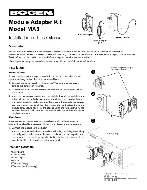
Module Adapter Kit Model MA3Installation and Use Manual©2004 Bogen Communications,Inc.All rights reserved.Specifications subject to change without notice.54-2127-01B 0409DescriptionThe MA3 Module Adapter Kit allows Bogen’s latest line of input modules to work with the D-Series line of amplifiers(Models DMA40,DMA80,DMA 160,DMP06,and DPA 160).One MA3 kit can adapt up to 3 modules in a single D-Series amplifier.T wo MA3 kits can be used in the same D-Series amplifier to adapt up to 6 modules.Note:Signal-processing output modules are not compatible with the D-Series line of amplifiers.InstallationMaster AdapterA master adapter must always be installed,but the two slave adapters are optional and may be installed on an as needed basis.1.Connect the power supply to the adapter.Wire tie the power supply cord to the connector if desired.2.Connect the module to the adapter and slide the power supply cord below the module.3.Insert the two screws supplied with the module through the module screw holes and then through the two washers,with the larger washer first and the smaller retaining washer second.Then,insert the module and adapter into the module bay by sliding them along the card guides inside the module bays.Secure them to the chassis using the two screws.A gap between the unit’s back panel and the module will exist to allow the power supply wire to exit.Slave BoardOnce the master module adapter is installed,the slave adapters can be installed if needed.1.Connect the module to the adapter.2.the card guides inside the module bays.the module to secure it to the chassis.module should be flush with the unit’s back panel.Master AdapterSlave Adapter(X2)Power SupplyWire tie the power supply Package Contents•Master Board • 2 Slave Boards •Power Supply •Wire Tie• 2 Washers (large)•2 Washers (small retaining)Limited WarrantyThe MA3 is warranted to be free from defects in material or workmanship for two (2) years from the date of sale to the original purchaser. Any part of the product covered by this warranty that, with normal installation and use, becomes defective will be repaired or replaced by Bogen, at our option, provided the product is shipped insured and prepaid to: Bogen Factory Service Department, 50 Spring Street, Ramsey, NJ 07446, USA. The product will be returned to you freight prepaid. This warranty does not extend to any of our products that have been subjected to abuse, misuse, improper storage, neglect, accident, improper installation or have been modified or repaired or altered in any manner whatsoever, or where the serial number or date code has been removed or defaced. THE FOREGOING LIMITED WARRANTY IS BOGEN’S SOLE AND EXCLUSIVE WARRANTY AND THE PURCHASER’S SOLE AND EXCLUSIVE REMEDY. BOGEN MAKES NO OTHER WARRANTIES OF ANY KIND, EITHER EXPRESS OR IMPLIED, AND ALL IMPLIED WARRANTIES OF MERCHANTABILITY OR FITNESS FOR A PARTICULAR PURPOSE ARE HEREBY DISCLAIMED AND EXCLUDED TO THE MAXIMUM EXTENT ALLOWABLE BY LAW. Bogen's liability arising out of the manufacture, sale or supplying of products or their use or disposition, whether based upon warranty, contract, tort or otherwise, shall be limited to the price of the product. In no event shall Bogen be liable for special, incidental or consequential damages (including, but not limited to, loss of profits, loss of data or loss of use damages) arising out of the manufacture, sale or supplying of products, even if Bogen has been advised of the possibility of such damages or losses. Some States do not allow the exclusion or limitation of incidental or consequen-tial damages, so the above limitation or exclusion may not apply to you. This warranty gives you specific legal rights, and you may also have other rights which vary from State to State.Products that are out of warranty will also be repaired by the Bogen Factory Service Department -- same address as above or call 201-934-8500. The parts and labor involved in these repairs are warranted for 90 days when repaired by the Bogen Factory Service Department. All shipping charges in addition to parts and labor charges will be at the owner's expense. All returns require a Return Authorization number.07/20/200450 Spring Street,Ramsey,NJ 07446,U.S.A.T el.201-934-8500,Fax:201-934-9832,。
fakra连接器定义-回复
什么是fakra连接器?
Fakra连接器是一种用于车载无线电连接的高频连接器。
它最早是由位于德国的Fischer Automotive Systems GmbH和博世集团(Bosch Group)联合开发的。
该连接器被广泛应用于汽车电子系统中,如车载导航、车载音响、天线等。
Fakra连接器的设计是为了满足汽车行业对高频信号传输的要求。
它采用了塑料外壳,具有优良的防尘、防水和抗震性能。
连接器内部采用了特殊的结构设计,以确保在高频率下仍能提供稳定的信号传输。
此外,Fakra 连接器的设计还考虑了易于安装和拆卸的需求,使得维修和更换变得更加方便。
Fakra连接器有多种类型,每一种类型的连接器都有特定的颜色和编码,以便区分。
根据不同的用途和信号传输要求,Fakra连接器可分为A型、B型、C型、D型、E型、F型等。
每一种类型的连接器都有其独特的特点和应用领域。
例如,A型连接器常用于FM和AM天线系统,而D型连接器则广泛应用于数字音频和视频信号传输。
Fakra连接器的应用不仅限于汽车行业,还逐渐应用于其他领域,如航空航天、通信设备等。
由于其稳定的信号传输性能和耐用的特点,Fakra连
接器成为许多领域中的首选连接器。
总之,fakra连接器是一种用于车载无线电连接的高频连接器。
它具有防尘、防水、抗震等特点,以及易于安装和拆卸的设计。
根据不同的用途和信号传输要求,Fakra连接器有多种类型可供选择。
在汽车行业以及其他领域,Fakra连接器已经得到了广泛的应用和认可。
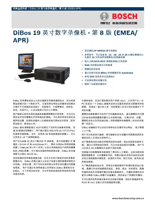
DiBos 采用博世举世公认的尖端数字录像和通信技术,成功将视频监控提升到一个新的水平。
它是各种应用场合的整体安防解决方案中不可或缺的组成部分,包括银行、大型零售店、地铁站、机场、市政中心、工业设施和公司办公大楼等。
客户能够以前所未有的速度检索重要图像和共享信息,并且可以更好地评估关键事态并采取相应的措施。
无论是在现场还是在远程网络位置,经授权的操作人员都能快速方便地访问信息,因而更加经济、高效地工作。
DiBos 能在清晰度高达 4CIF 的情况下支持实况查看和录像。
凭借 30 路复合视频输入,用户能以高达 450/375 ips (NTSC/PAL)的速率存储图像。
另外,在具有 30 条视频通道的装置上,可以记录多达 10 个音频数据流。
用户可以连接 32 多达个额外的 IP 音频源。
其中包括博世 IP 摄像机(Dinion IP 和 AutoDome IP)、博世 MPEG4 网络视频编码器(VideoJet 和 VIP X 系列)以及众多制造商生产的网络摄像机的 JPEG 图像。
对于每台连接的网络音频设备,DiBos 的存储速度可以高达 30/25 ips。
该系统提供多种高级查看功能,并且允许进行高度灵活的录像和图像访问。
DiBos 的真正强大之处在于快速方便的图像和信息访问功能。
如有必要,用户可在任何时候从世界任何位置访问图像和信息。
用户可通过专用网络或公共网络与 DiBos 通信和访问DiBos。
为了实现这些目的,可以将系统连接到各种各样的外围设备和系统。
它拥有独特、灵活扩展的图形用户界面 (GUI),允许用户从一台PC 机或另一个 DiBos 查看来自多台远程系统的实况图像和存档图像。
凭借这一强大的工具,安防管理人员可以同时监督多个不同的位置。
摄像机和查看模式可由用户手动编程或选定。
每台摄像机均可通过本地或远程装置提供窗内云台控制功能。
日期/时间、位置、摄像机名称以及所连接设备(如探测器和传感器等)的状态与图像一同显示。
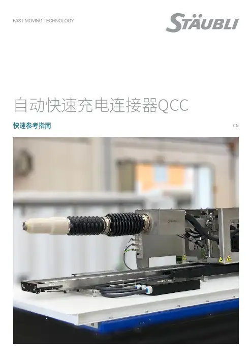
自动快速充电连接器QCC快速参考指南CN2 自动快速充电连接器 QCC|快速参考指南通用场地布局供应范围ACD 和插座及子部件图解接地信号触子磁铁元件微动开关固定点位(8 个)控制箱自动快速充电连接器 QCC|快速参考指南 3QCC-ACD 将被放置在外罩内。
为安装 ACD,外罩应具有如下所示的最小尺寸至少保留如下图所示的5个方位的维护检修通道。
空间和安装42.3 m0.8 m1.m213注意事项请确保根据制造商的建议,按照最小弯曲半径来规划电缆布线。
1. ACD - 从侧面,特别是电源箱一侧。
2. ACD - 从正面,也需要打开以进行插合。
3. ACD - 从上面。
4. 插座 - 从上面5. 旋转扳手的空间(两侧)Scale 1 : 534customer control box connection B ( 1 : 2 )AScrew M10x..... (to be defined according to the customer frame thickness)Tightening torque: 10Nm Washer For height adjustments and minor levelling 8M 550600注意事项控制箱可安装在最远距离ACD2米的地方。
尺寸控制箱螺钉 M10x...(根据客户的框架厚度确定)。
拧紧扭矩:10 N m 垫圈调平 5QCC2 – 插座(ACD 配对装置)179()294x 84x M 1620412080221624021525180(40)13()104x M 2251008x M 10x 23A6 自动快速充电连接器 QCC|快速参考指南带有接线细节的信息图QCC2I/O (最多 30 根线):0.5 mm² – 1.5 mm² 马达电源(3 根线):2.5 mm² – 4 mm²微动开关电源线 U+/V-/GND最大 120 mm²/外直径10 mm – 32 mm 建议采用 5 级或 6 级线束/绞线CombiTac 接口电缆信号(3 个双绞线绞合线对): 0.25 mm² - 0.75 mm² I/O (最多 30 根线):0.5 mm² - 1.5 mm² 马达电源(3 根线):2.5 mm² – 4 mm²辅助触子(插座端) 最多 6 根线:0.14 mm² – 1 mm²微动开关最多 4 根线:最大 0.5 mm²整车控制器 (VCU)辅助触子微动开关充电站CombiTac 接口电缆ACD 控制 (PLC/SPS)V-信号 1信号 2马达V-整车控制器 (VCU)辅助触子微动开关V-充电站V-GNDU+信号 2马达CombiTac 接口电缆ACD 控制(PLC/SPS)QCC3自动快速充电连接器 QCC|快速参考指南 7QCC3 + 温度传感器可编程逻辑控制器 (PLC)为驱动 ACD,需要对 PLC 进行编程,并通过CombiTac 接口电缆连接到史陶比尔控制箱。
博⼠(BOSCH)连接器样本Plugs andPlug-In Connectionso k e n f e e : €5.00y CATALOG 2005|2006Reliable contacts in all respectsIrrespective of conditions,Bosch plug-in connec-tions always comply fully with all electrical,mechani-cal,and geometrical stipulations.They guarantee extremely low contact resistance throughout the vehicle’s complete service life,and have very high in-sulation resistance,as well as being watertight and proof against humidity and saline fog.Bosch plug-in connections are easily pluggable and unpluggable,and the connection of wires and terminals is an easy matter.The standard for maximum reliabilityLow-way plug-in connectionsPlug-in connections serve to transfer signals and power to electronic and/or electrical components.The ever-increasing use of electronic components in the vehicle leads to an attendant increase in the demands made on connection reliability.High Contact Reliabilitywith Bosch Plug-In Connections3-way “Compact plug 3”with secondary contact locking and CPA (Connector Position Assume)The lever/slide principle for simple assemblyNew plug-in techniques:The 64-way plug-in connectionOn our 64-way plug-in connection too,the fact that the lever/slide combination permits low opera-ting forces contributes to uncomplicated,high-speed assembly.At the same time,it ensures high levels of reliability when the plug is in position.In those cases in which installation space is limited,the plug can also be inserted without the lever,and only the slide is needed.Low-way plug-in connections –no other plug can compare with our 38-pole plug-in connectionWith its 38-pole plug-in connection,Bosch hasintroduced an innovation to the market:This plug-in connection features 2.5 mm contact spacing and 3.0 mm row spacing.It has been specially designed for hybrid ECU’s which are directly attached to the engine.The swivel-type metal lever reduces the plug-in force to less than 100 N,so that there are no difficulties involved in plugging-in on the vehicle and during service in the workshops.A mechanical coding function makes false plugging/doc/103ada29647d27284b7351b4.html pact design with high resistance to vibration.64-way plug-in connection for electronic gasoline-engine managementTwo 38-way passenger-car plugs for MotronicCode A B C Colour Order Number Terminals17.0––black 1 928 403 137Junior Power Timer 17.0––blue 1 928 403 126(see page 22)2 4.0––grey 1 928 403 722Code A B C Colour Order Number Terminals19.0––black 1 928 403 110Junior Power Timer 19.0––grey 1 928 403 915(see page 22)2 5.0––grey 1 928 404 550Code A B C D Colour Order Number Terminals120.0––13.0black 1 928 403 146Junior Power Timer 520.0––11.5black 1 928 403 813(see page 22) Code A B C Colour Order Number Terminals124.0––black 1 928 403 202Junior Power Timer 211.0––grey 1 928 403 816(see page 22)Code A B C Colour Order Number Terminals17.0––black 1 928 403 698Junior Power Timer 17.0––colourless 1 928 404 476(see page 22)2 4.0––grey 1 928 403 9203 5.5– 3.5colourless 1 928 404 707Code A B C Colour Order Number Terminals19.0––black 1 928 403 870Junior Power Timer(see page 22)Code A B C D Colour Order Number Terminals120.0––13.0black 1 928 404 221Junior Power Timer 520.0––11.5black 1 928 404 219(see page 22) Code A B C Colour Order Number Terminals124.0––black 1 928 404 629Junior Power Timer 111.0––grey 1 928 404 631(see page 22)Code A B C Colour Order Number Terminals17.0––black 1 928 403 192Junior Power Timer 17.0––blue 1 928 403 194(see page 22) Code A B C Colour Order Number Terminals19.0––black 1 928 403 196Junior Power Timer 19.0––grey 1 928 403 914(see page 22)Code A B C D Colour Order Number Terminals120.0––13.0black 1 928 403 200Junior Power Timer 520.0––11.5black 1 928 403 812(see page 22) Code A B C Colour Order Number Terminals124.0––black 1 928 403 204Junior Power Timer 211.0––grey 1 928 403 815(see page 22)Code A B C Colour Order Number Terminals17.0––black 1 928 404 072Bosch Damping Terminal(see page 22)Code A B C Colour Order Number Terminals19.0––black 1 928 404 073Bosch Damping Terminal 19.0––grey 1 928 404 074(see page 22)Code A B C D Colour Order Number Terminals120.0––13.0black 1 928 404 075Bosch Damping Terminal(see page 22)Code A B C Colour Order Number Terminals17.0––black 1 928 403 874Bosch Damping Terminal 17.0––brown 1 928 403 876(see page 22)2 4.0––black 1 928 404 1142 4.0––white 1 928 403 8783 5.5– 3.5grey 1 928 404 2134 5.5 3.5–blue 1 928 404 215Code A B C Colour Order Number Terminals19.0––black 1 928 403 966Bosch Damping Terminal 19.0––blue 1 928 403 970(see page 22)2 5.0––black 1 928 403 968Code A B C Colour Order Number Terminals112.0––black 1 928 403 736Bosch Damping Terminal(see page 22)Code A B C D Colour Order Number Terminals120.0––13.0black 1 928 403 738Bosch Damping Terminal 520.0––11.5black 1 928 403 836(see page 22) Code A B C Colour Order Number Terminals129.0––black 1 928 403 742Bosch Damping Terminal(see page 22)Code A B C Colour Order Number Terminals19.0––black19284034361Junior Power Timer(see page 22) Code A B C Colour Order Number Terminals112.0––black19284034401Junior Power Timer 112.0––black19284034412(see page 22)Code A B C Colour Order Number Terminals19.0––black19284038092Junior Power Timer(see page 22)。
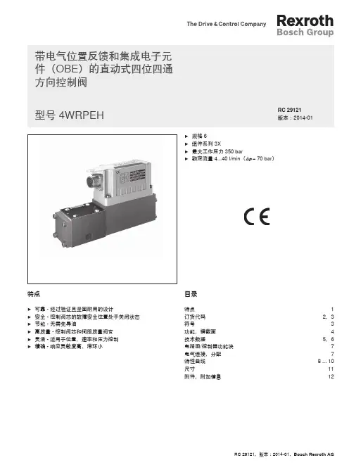
1/16液压-电气压力开关类型 HED 8组件系列 2X最大工作压力 630 bar CE,CCC,ULRC 50061/02.12替代对象:07.06目录– 用于底板安装/管路安装– 用于法兰连接,符合 ISO 16873– 作为垂直叠加元件,与叠加阀板相连接,符合 ISO 4401– 5 个压力等级– 4 种调节元件类型类型:• 带或不带保护帽的调节杆 • 带刻度调节杆,带或不带保护帽 • 带刻度旋钮 • 带刻度可锁定旋钮– 电气连接• 带大型方形连接器 • 带 M12 x 1 连接器– 微动开关,带常闭/常开触点功能– 电流零电位转换(1 mA 至 2 A)– 压力范围经过 UL 认证,高达 350 barTB0004+TB0040特点目录 页码特点 1订货代码2功能,横截面,符号 3技术数据4特性曲线 切换压差 6单元尺寸 7安装信息10订货代码:叠加阀板,规格 6 12符号,型号:叠加阀板,规格 6 12单元尺寸:叠加阀板,规格 6 13订货代码:叠加阀板,规格 10 14符号,型号:叠加阀板,规格 10 14单元尺寸:叠加阀板,规格 10 15电气连接 16插头16订货代码柱塞式压力开关法兰连接(ISO 16873)1)= OH底板安装 = OP管路安装 = OA组件系列 20 至 29 = 2X(20 至 29:安装和连接尺寸不变)最大压力等级 50 bar = 50最大压力等级 100 bar = 100最大压力等级 200 bar = 200最大压力等级 350 bar = 350最大压力等级 630 bar 2)= 630电气连接带连接器的单个连接符合 DIN EN 175301-803,大型方形连接器不带插头 3)= K14 3)带连接器的单个连接符合 IEC 61076-2-101,M12 x 1,A 类型,不带插头 3)= K35 3)明文形式的更多详细信息密封材料无代码 =NBR 密封件V = FKM 密封件MT =低温密封件(最大 315 bar)注意:请务必遵守密封件与所用液压油的兼容性。
Plugs andPlug-In Connectionso k e n f e e : €5.00y CATALOG 2005|2006Reliable contacts in all respectsIrrespective of conditions,Bosch plug-in connec-tions always comply fully with all electrical,mechani-cal,and geometrical stipulations.They guarantee extremely low contact resistance throughout the vehicle’s complete service life,and have very high in-sulation resistance,as well as being watertight and proof against humidity and saline fog.Bosch plug-in connections are easily pluggable and unpluggable,and the connection of wires and terminals is an easy matter.The standard for maximum reliabilityLow-way plug-in connectionsPlug-in connections serve to transfer signals and power to electronic and/or electrical components.The ever-increasing use of electronic components in the vehicle leads to an attendant increase in the demands made on connection reliability.High Contact Reliabilitywith Bosch Plug-In Connections3-way “Compact plug 3”with secondary contact locking and CPA (Connector Position Assume)The lever/slide principle for simple assemblyNew plug-in techniques:The 64-way plug-in connectionOn our 64-way plug-in connection too,the fact that the lever/slide combination permits low opera-ting forces contributes to uncomplicated,high-speed assembly.At the same time,it ensures high levels of reliability when the plug is in position.In those cases in which installation space is limited,the plug can also be inserted without the lever,and only the slide is needed.Low-way plug-in connections –no other plug can compare with our 38-pole plug-in connectionWith its 38-pole plug-in connection,Bosch hasintroduced an innovation to the market:This plug-in connection features 2.5 mm contact spacing and 3.0 mm row spacing.It has been specially designed for hybrid ECU’s which are directly attached to the engine.The swivel-type metal lever reduces the plug-in force to less than 100 N,so that there are no difficulties involved in plugging-in on the vehicle and during service in the workshops.A mechanical coding function makes false plugging pact design with high resistance to vibration.64-way plug-in connection for electronic gasoline-engine managementTwo 38-way passenger-car plugs for MotronicCode A B C Colour Order Number Terminals17.0––black 1 928 403 137Junior Power Timer 17.0––blue 1 928 403 126(see page 22)2 4.0––grey 1 928 403 722Code A B C Colour Order Number Terminals19.0––black 1 928 403 110Junior Power Timer 19.0––grey 1 928 403 915(see page 22)2 5.0––grey 1 928 404 550Code A B C D Colour Order Number Terminals120.0––13.0black 1 928 403 146Junior Power Timer 520.0––11.5black 1 928 403 813(see page 22) Code A B C Colour Order Number Terminals124.0––black 1 928 403 202Junior Power Timer 211.0––grey 1 928 403 816(see page 22)Code A B C Colour Order Number Terminals17.0––black 1 928 403 698Junior Power Timer 17.0––colourless 1 928 404 476(see page 22)2 4.0––grey 1 928 403 9203 5.5– 3.5colourless 1 928 404 707Code A B C Colour Order Number Terminals19.0––black 1 928 403 870Junior Power Timer(see page 22)Code A B C D Colour Order Number Terminals120.0––13.0black 1 928 404 221Junior Power Timer 520.0––11.5black 1 928 404 219(see page 22) Code A B C Colour Order Number Terminals124.0––black 1 928 404 629Junior Power Timer 111.0––grey 1 928 404 631(see page 22)Code A B C Colour Order Number Terminals17.0––black 1 928 403 192Junior Power Timer 17.0––blue 1 928 403 194(see page 22) Code A B C Colour Order Number Terminals19.0––black 1 928 403 196Junior Power Timer 19.0––grey 1 928 403 914(see page 22)Code A B C D Colour Order Number Terminals120.0––13.0black 1 928 403 200Junior Power Timer 520.0––11.5black 1 928 403 812(see page 22) Code A B C Colour Order Number Terminals124.0––black 1 928 403 204Junior Power Timer 211.0––grey 1 928 403 815(see page 22) Code A B C Colour Order Number Terminals129.0––black 1 928 403 222Junior Power Timer(see page 22)Code A B C Colour Order Number Terminals17.0––black 1 928 404 072Bosch Damping Terminal(see page 22)Code A B C Colour Order Number Terminals19.0––black 1 928 404 073Bosch Damping Terminal19.0––grey 1 928 404 074(see page 22)Code A B C Colour Order Number Terminals112.0––black 1 928 404 7451Bosch Damping Terminal112.0––black 1 928 404 8252(see page 22)With special seal.Code A B C D Colour Order Number Terminals120.0––13.0black 1 928 404 075Bosch Damping Terminal(see page 22)Code A B C Colour Order Number Terminals17.0––black 1 928 403 874Bosch Damping Terminal 17.0––brown 1 928 403 876(see page 22)2 4.0––black 1 928 404 1142 4.0––white 1 928 403 8783 5.5– 3.5grey 1 928 404 2134 5.5 3.5–blue 1 928 404 215Code A B C Colour Order Number Terminals19.0––black 1 928 403 966Bosch Damping Terminal 19.0––blue 1 928 403 970(see page 22)2 5.0––black 1 928 403 968Code A B C Colour Order Number Terminals112.0––black 1 928 403 736Bosch Damping Terminal(see page 22)Code A B C D Colour Order Number Terminals120.0––13.0black 1 928 403 738Bosch Damping Terminal 520.0––11.5black 1 928 403 836(see page 22)Code A B C Colour Order Number Terminals124.0––black 1 928 403 740Bosch Damping Terminal 211.0––grey 1 928 404 525(see page 22)Code A B C Colour Order Number Terminals129.0––black 1 928 403 742Bosch Damping Terminal(see page 22)Code A B C Colour Order Number Terminals19.0––black19284034361Junior Power Timer(see page 22) Code A B C Colour Order Number Terminals112.0––black19284034401Junior Power Timer 112.0––black19284034412(see page 22) Code A B C D Colour Order Number Terminals520.0––11.5black19284042251Junior Power Timer(see page 22)Code A B C Colour Order Number Terminals19.0––black19284038092Junior Power Timer(see page 22)Code A B C Colour Order Number Terminals17.0––black1928404166Bosch Damping Terminal 17.0––brown1928404570(see page 22)2 4.0––white1928404571Code A B C Colour Order Number Terminals19.0––black1928404163Bosch Damping Terminal 2 5.0––black1928404368(see page 22)19.0––blue1928404572Code A B C Colour Order Number Terminals112.0––black1928404160Bosch Damping Terminal(see page 22)Code A B C D Colour Order Number Terminals520.0––11.5black19284043701Bosch Damping Terminal 520.0––11.5black19284045982(see page 22)Code A B C Colour Order Number Terminals124.0––black19284046481Bosch Damping Terminal(see page 22)Dimensions l x w x h38x2 Offer drawing number C227 Order number1928401Dimensions l x w x h88x2x8 mm Offer drawing number C280202198 Order number1281099005Dimensions l x w x h88x2x8 mm Offer drawing number C 280 204 853 Order number 1 928 400 889gold-plated, for FLR wires gold-plated, for FLR wires gold-plated, for FLR wires964 972-1Insulation ØOrder No. 963 292-1Dimensions l x w x h80x42x28 mm Offer drawing number D928 003 25A Order number1928404513 without leverDimensions l x w x h80x42x25 mm Offer drawing number C928 002 84A Order number1928404322AMP Junior Power Timerwith additional steel springwith additional steel springwith additional steel spring。