手动油泵说明书SYB
- 格式:pdf
- 大小:280.08 KB
- 文档页数:6

Automotive | Commercial |Industrial 2Pump Models Repair Kit# Comments Service Kit List - Pumps | 7/1/2013*DISCONTINUED KITS - KITS AVAILABLE UNTIL YEAR NOTED I.E. (DISC-2015)LYNX SERIES PUMPS1110-009, 1110-010, 1110-007832865 (DISC -2015)Air valve kit (Made in Sweden)1110-009, 1110-010, 1110-007833110Air valve kit (Gen 2 -Made in EU)1110-011 & 1160-009832954 (DISC -2015)Air valve kit (Made in Sweden)1110-011 & 1160-009833113Air valve kit (Gen 2 -Made in EU)1110-009 & 1110-010832928 (DISC -2015)Fluid seal kit (Made in Sweden)1110-009 & 1110-010833109Fluid seal kit (Gen 2 -Made in EU)1110-007832864 (DISC -2015)Fluid seal kit (Made in Sweden)1110-007833111Fluid seal kit (Gen 2 -Made in EU)1160-009832953Fluid seal kit 1110-011832960 (DISC 2015)Fluid seal kit (Made in Sweden)1110-011833112Fluid seal kit (Gen 2 -Made in EU)PANTHER HP SERIES PUMPSPanther HP Series Pumps - All900019Air motor kit - Trip Rod Assembly Panther HP Series Pumps - All900031Air motor kit - SOFT parts only Panther HP Series Pumps - All831614Air motor assembly kit- Includes Piston Panther HP Series Pumps - All oil831613Air - complete assembly 1130-015, 1130-017 & 1130-020900020Fluid seal kit 1130-016, 1130-018 &1130-021900021Fluid seal kit 1130-015, 1130-017 & 1130-020831612N Fluid - complete assembly 1130-016, 1130-018 & 1130-021831615N Fluid - complete assembly TIGER HP SERIES PUMPSTiger HP Series Pumps - All900027Air motor kit - Trip Rod Assembly Tiger HP Series Pumps - All900028Air motor kit - SOFT parts only Tiger HP Series Pumps - All831671Air - complete assembly 1130-019, 1130-025 & 1130-026900020Fluid seal kit 1160-007828070Fluid seal kit (Stainless Steel)1130-019, 1130-025 & 1130-026831672N Fluid - complete assembly LION HP SERIES PUMPSLion HP Series Pumps - All900027Air motor kit - Trip Rod Assembly Lion HP Series Pumps - All900028Air motor kit - SOFT parts only Lion HP Series Pumps - All832101Air - complete assembly 1130-024900020Fluid seal kit 1130-027900030Fluid seal kit 1130-024V827065Quad-ring only (Viton)1130-024832106N Fluid - complete assembly 1130-027831139N Fluid - complete assemblyAutomotive | Commercial | Industrial 3Service Kit List - Pumps | 7/1/2013 Pump Models Repair Kit# Comments*DISCONTINUED KITS - KITS AVAILABLE UNTIL YEAR NOTED I.E. (DISC-2015)RETIRED OIL PUMPSJet Power 4:1Jet 4:1 All 810071 (DISC-2018)Air motor assemblyBobcat Series PumpsBobcat Series Pumps - All827711 (DISC- 2017)Air Valve & Seals1130-005827712 (DISC - 2017)Fluid seal kit1110-001, 1110-003,1111-002, 1111-003,828069 (DISC - 2017)Fluid seal kit (above serial #196000)1110-005 & 1110-006900020Fluid seal kit1160-002, 1160-003,1160-006, & 1131-002828070Fluid seal kit (Stainless Steel)NOTES:Automotive | Commercial |Industrial 4Pump Models Repair Kit# Comments Service Kit List - Pumps | 7/1/2013*DISCONTINUED KITS - KITS AVAILABLE UNTIL YEAR NOTED I.E. (DISC-2015)LYNX 55:11151-027 & 1151-028833038Air motor kit 1151-027 & 1151-028833039Packing Seal kit 1151-027 & 1151-028833040Foot Valve Kit 1151-027 & 1151-028833041HP Piston/cylinder & check valve PANTHER HP 50:1Panther HP Series Pumps - All900019Air motor kit - Trip Rod Assembly Panther HP Series Pumps - All831614Air motor assembly kit- Includes Piston Panther HP Series Pumps - All grease831619Air - complete assembly Panther HP Series Pumps - All grease900022Fluid seal kit 1150-009831616Fluid - complete assembly 1150-010831617Fluid - complete assembly 1150-011831618Fluid - complete assembly 1150-017 (stub pump)832185Fluid - complete assembly LION HP 50:1Lion HP Series Pumps - All900027Air motor kit - Trip Rod Assembly Lion HP Series Pumps - All900028Air motor kit - SOFT parts only Lion HP Series Pumps - All832101Air - complete assembly Lion HP Series Pumps - All grease900029Fluid seal kit 1150-015832122Fluid - complete assembly 1150-018 (stub pump)832260Fluid - complete assembly RETIRED GREASE PUMPSJet Power 50:1Jet 50:1 - All810071 (DISC-2018)Air motor assembly Jet 50:1 : 1150-001,1150-003, 1150-004, 1150-005, 7110-004, 7110-005, 7110-006,7110-007, 7210-001, 7210-003, 7210-004, 754, 763, 764, 767,870, 878, 2854, & 2874816348 (DISC-2018)Fluid seal kit - #267560 and aboveAutomotive | Commercial | Industrial 5Service Kit List - Pumps | 7/1/2013 Pump Models Repair Kit# Comments*DISCONTINUED KITS - KITS AVAILABLE UNTIL YEAR NOTED I.E. (DISC-2015)DIAPHRAGM PUMPS - CENTERFLOCF-10 Pump 1120-029833206Air valve kitCF-10 Pump 1120-029833207Stroke sensor kitCF-10 Pump 1120-029833236Check Ball kitCF-10 Pump 1120-029833209Ball Seats, O-rings, ball guidesCF-10 Pump 1120-029833331Bushing, seal, push rod (Prior to 2/1/13)CF-10 Pump 1120-029833336Bushing, seal, push rod (AFTER 2/1/13)CF-10 Pump 1120-029833238Diaphragms kit (Prior to 2/1/13)CF-10 Pump 1120-029833337Diaphragms kit (AFTER 2/1/13)CF-10 Pump 1120-029833340Retrofi t kit (include diaphragms,diaphragm nuts, & central shaft) - Updatespumps prior to 2/1/13 to new design.CF-15 Pump 1120-023 / 1120-025 / 1120-027 / 1120-028833206Air valve kitCF-15 Pump 1120-023 / 1120-025 / 1120-027 / 1120-028833207Stroke sensor kitCF-15 Pump 1120-023 / 1120-025833208Check Ball kitCF-15 Pump 1120-027 / 1120-028833236Check Ball kitCF-15 Pump 1120-023 / 1120-025 833209Ball Seats, O-rings, ball guidesCF-15 Pump 1120-027 / 1120-028833330Ball Seats, O-rings, ball guidesCF-15 Pump 1120-023 / 1120-025 / 1120-028833210Bushing, seal, push rod (Prior to 2/1/13)CF-15 Pump 1120-023 / 1120-025 /1120-028833332Bushing, seal, push rod (AFTER 2/1/13)CF-15 Pump 1120-027833237Bushing, seal, push rod (Prior to 2/1/13)CF-15 Pump 1120-027833333Bushing, seal, push rod (AFTER 2/1/13)CF-15 Pump 1120-023 / 1120-025 / 1120-027 / 1120-028833211Diaphragms kit (Prior to 2/1/13)CF-15 Pump 1120-023 / 1120-025 / 1120-027 / 1120-028833338Diaphragms kit (AFTER 2/1/13)CF-15 Pump 1120-023 / 1120-025 / 1120-027 / 1120-028833341Retrofi t kit (include diaphragms, diaphragm nuts,& central shaft) - Updates pumps prior to 2/1/13to new design.CF-30 Pump 1120-024 / 1120-026 / 1120-031833212Air valve kitCF-30 Pump 1120-024 / 1120-026 / 1120-031833207Stroke sensor kitCF-30 Pump 1120-024 833213Check Ball kitCF-30 Pump 1120-026 / 1120-031833233Check Ball kitCF-30 Pump 1120-024 833214Ball Seats, O-rings, ball guidesCF-30 Pump 1120-026 / 1120-031833234Ball Seats, O-rings, ball guidesCF-30 Pump 1120-024 833215Bushing, seal, push rod (Prior to 2/1/13)CF-30 Pump 1120-024 833334Bushing, seal, push rod (AFTER 2/1/13)CF-30 Pump 1120-026 / 1120-031833235Bushing, seal, push rod (Prior to 2/1/13)CF-30 Pump 1120-026 / 1120-031833335Bushing, seal, push rod (AFTER 2/1/13)CF-30 Pump 1120-024 / 1120-026 / 1120-031833216Diaphragms kit (Prior to 2/1/13)CF-30 Pump 1120-024 / 1120-026 / 1120-031833339Diaphragms kit (AFTER 2/1/13)CF-30 Pump 1120-024 / 1120-026 / 1120-031833342Retrofi t kit (include diaphragms, diaphragm nuts,& central shaft) - Updates pumps prior to 2/1/13to new design.Automotive | Commercial |Industrial 6Pump Models Repair Kit# Comments Service Kit List - Pumps | 7/1/2013*DISCONTINUED KITS - KITS AVAILABLE UNTIL YEAR NOTED I.E. (DISC-2015)DIAPHRAGM PUMPS - CONVENTIONAL 1/2" Diaphragm Pump Poly 1120-011S 832903Air seal kit 1/2" Diaphragm Pump Poly 1120-011S832902Fluid seal kit 1" Diaphragm Pump Aluminum 1120-013S832905Air seal kit 1" Diaphragm Pump Aluminum 1120-013S832904Fluid seal kit 1" Mixing Diaphragm Pump Aluminum 1120-014S832907Air seal kit 1" Mixing Diaphragm Pump Aluminum 1120-014S832906Fluid seal kit 1' Diaphragm Pump Aluminum 1120-015S833103Air seal kit 1' Diaphragm Pump Aluminum 1120-015S832973Air assembly kit 1' Diaphragm Pump Aluminum 1120-015S832974Fluid seal kit 1-1/2" Diaphragm Pump Aluminum1120-017831975Air seal kit 1-1/2" Diaphragm Pump Aluminum1120-017831976Fluid seal kit3/4" Diaphragm Pump Aluminum 1120-019831589Air seal kit3/4" Diaphragm Pump Aluminum 1120-019833132Air assembly kit3/4" Diaphragm Pump Aluminum 1120-019831591Fluid seal kit1/2" DEF Pump 1120-020S 833100Air seal kit1/2" DEF Pump 1120-020S 832903Air assembly kit1/2" DEF Pump 1120-020S 832978Fluid seal kit1" DEF Pump 1120-021S 833104Air seal kit1" DEF Pump 1120-021S 832975Air assembly kit1" DEF Pump 1120-021S 832976Fluid seal kit2" Diaphragm Pump Aluminum 1120-030S 833175Air seal kit2" Diaphragm Pump Aluminum 1120-030S 833173Fluid seal kit2" Diaphragm Pump Aluminum 1120-030S 833174Air assembly kit1/2' Diaphragm Pump Polypropylene & Aluminum1120-011, 1120-012831589 (DISC-2015)Air seal kitAutomotive | Commercial | Industrial 7Service Kit List - Pumps | 7/1/2013 Pump Models Repair Kit# Comments*DISCONTINUED KITS - KITS AVAILABLE UNTIL YEAR NOTED I.E. (DISC-2015)1/2' Diaphragm Pump Polypropylene & Aluminum1120-011, 1120-012831934 (DISC-2015)Air assembly kit1/2' Diaphragm Pump Polypropylene & Aluminum1120-011, 1120-012831591 (DISC-2015)Fluid seal kit1' Diaphragm Pump Aluminum1120-013, 1120-014831590 (DISC-2015)Air seal kit1' Diaphragm Pump Aluminum1120-013, 1120-014831926 (DISC-2015)Air assembly kit1' Diaphragm Pump Aluminum1120-013832562 (DISC-2015)Air valve body1' Diaphragm Pump Aluminum1120-013, 1120-014831592 (DISC-2015)Fluid seal kit1' Diaphragm Pump Aluminum1120-015831622 (DISC-2018)Air seal kit1' Diaphragm Pump Aluminum1120-015831621 (DISC-2018)Fluid seal kit3/4" Acetal Ball831594 (DISC-2015)3/4" Check Ball1" Delrin Ball827168 (DISC-2015)1" Check Ball1" Viton Ball828063 (DISC-2015)1" Check Ball1" Tefl on Ball825021 (DISC-2015)1" Check BallNOTESDEF PUMPS1200-013833135 Seal - mechanical1200-013833136 Impeller, diffuser, O-ringCustomer Support800-747-5300 or 828-645-4261(Mon. - Fri., 8 am - 5 pm ET)• Order entry• Product availability•Pricing• Basic product information• Shipping dates and delivery information• Product return authorizationOrder by fax800-763-0840 or 828-658-0840• Fax orders day or night• Free-up phone lines• Order confirmed next business day by fax or e-mail Technical Support800-747-5300 or 828-645-4261(Mon. - Fri., 8 am - 5 pm ET)• Repair Advice• Product application recommendations• Warranty claims and returns•ServicebulletinsE-mail Ordering & Online SupportWebsite: E-mail: *****************E-mail Ordering:******************* Service Bulletins/ServiceBulletinsBalcrank Corporation | 115 Reems Creek Rd. Weaverville, NC 28787 | 800-747-5300 | |*****************| SB0001-PUMPS。

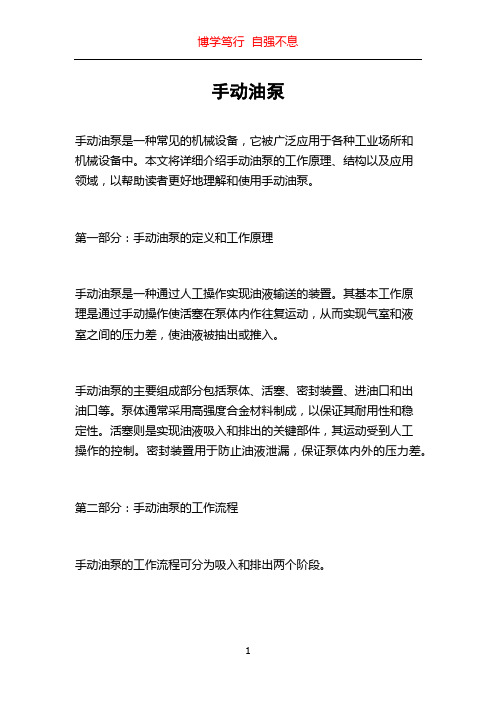
l Double acting - pumps on up and down strokes l 316 stainless steel/ bronze construction l Five models cover max. pressures 50 - 700 bar l Compatible with water, oil and other liquids l Reliable- British design & manufacture l Sturdy construction- for extreme environments l Long life hard chromed stainless piston rod l Soft-seat check valve for positive sealing l Pressure gauge, release & relief valve options l User serviceable sealing & seating components l Detachable 450mm or 625mm operating handle l Nitrile seals standard - optional EPDM/ Viton®l Universal mounting orientationl Optional range of 316 fixed mounting reservoirs F E AT U R E SMicropac Hydraulic Hand Pumpfor Potentially Explosive AtmospheresADJUSTABLE RELIEF VALVE(WHERE FITTED)PRESSURE HOLD/ RELEASE VALVE (WHERE FITTED)SPIGOT FOR DETACHABLE450/625mm OPERATING HANDLE4 x 316 FIXING SCREWS SUPPLIED FOR RESERVOIR/PLATE MOUNTINGINLET HOSE ADAPTOR FOR SUCTION TUBE & STRAINEROPTIONAL STANDPIPE/ NPT ADAPTOR9/16"-18 UNF/SAE OUTLET PORT (700 BAR MODEL: G3/8) WITH G1/4 MALE ADAPTOR63mm PRESSURE GAUGE (OPTIONAL)TYPICAL APPLICATIONS: HYDROSTATIC & LEAK TESTING PRESSURE TEST RIGS HYDRAULIC TEST STANDS FILLING & CHARGINGHYDRAULIC CYLINDER ACTUATIONMANUAL OVER-RIDE/ SHUTDOWN SYSTEMSin® SEE OVERLEAF FOR SUITABILITY TO ENVIRONMENTUKEX, ATEX and IEC Ex certifiedAtmosphereAll equipment intended for use in potentially explosive atmospheres is marked in accordance with the requirements of the Equipment and Protective Systems Intended for use in Potentially Explosive Atmospheres Regulations 2016, the ATEX Directive 2014/34/EU, and BS EN ISO 80079-36:2016 .The product nameplate showsŸthe manufacturer (Sarum Hydraulics Ltd.)Ÿthe product type identificationŸthe UKCA marking, denoting conformity with the Equipment and Protective Systems Intended for use in Potentially Explosive Atmospheres Regulations 2016Ÿthe CE marking, denoting conformity with all the essential requirements of the ATEX Directive 2014/34/EUŸmarking as detailed below, denoting the compatibility of the equipment within the operating environment, firstly as defined by the Equipment and Protective Systems Intended for use in Potentially Explosive Atmospheres Regulations 2016 and the ATEX Directive 2014/34/EU and then as defined by the requirements of BS EN ISO 80079-36:2016Ÿserial numberŸcertificate issuer and reference in the defined formAccording to the Equipment and Protective Systems Intended for use in Potentially Explosive Atmospheres Regulations 2016 and the ATEX Directive 2014/34/EU, the marking denotes that the equipment is non-electrical intended to be used in Surface Industry classified as both Gas Explosive Atmosphere - Zone 1 and Explosive Atmosphere of Combustible Dust - Zone 21.According to BS EN ISO 80079-36:2016, the marking denotes that the equipment is non-electrical conforming to this standard both for EPL Gb for use in explosive gas atmospheres of Group IIC and ignition temperature greater than 85 °C, and for EPL Db for explosive dust atmospheres containing dusts of Group IIIC and maximum surface temperature less than 85 °C.MediaSubject to suitability of materials of construction, the unit is compatible for operation with group 1 liquids up to 500 bar and group 2 liquids up to 1000 bar according to the classification of liquids under the Pressure Equipment Directive 2014/68/EU, which cross refers to the Classification, Labelling and Packaging (CLP) Directive 1272/2008. These may be summarised as follows, but the text of the Directive Article 13 paragraph 1 fully defines those substances categorised as groups 1 and 2.Group 1: explosive, extremely flammable, highly flammable, flammable (where the maximum allowable temperature is above flashpoint), toxic, serious health hazards, oxidising Group 2: all other liquidsElastomer sealing options are nitrile, fluorocarbon and ethylene propylene, specified at the time of ordering.Please consult with the factory if in doubt.CertificationThis equipment is supplied with a Declaration of Conformity in accordance with the requirements of either the Equipment and Protective Systems Intended for use in Potentially Explosive Atmospheres Regulations 2016, or the ATEX Directive 2014/34/EU, or BS EN ISO 80079-36:2016. Any modificationto the equipment by a third party may invalidate the certification.II 2 GEx h IIC T6 GbII 2 DEx h IIIC T85°C DbSUITABILITY FOR THE OPERATING ENVIRONMENTINSTALLATION & MAINTENANCEINSTALLATION continuedused. Lower the pump into position and secureusing the four M8 x 65 long socket head cap screws supplied, tighten evenly to a torque of 15Nm.Before mounting the reservoir, consider ergonomics of pump handle operation; refer to pump dimensions section. Mount the reservoir on a surface that can withstand handle forces during pumping to maximum required pressure. Use the mounting holes provided; fixings are not supplied.Remote mounting: mounting detail as for reservoir. Make connection to inlet using suitable coupling, ensuring media is filtered.CONNECTIONSThe outlet connection is a 9/16" UNF SAE female port (G3/8 on 7cc/ 700 bar unit); a G1/4 male 60° coned adaptor is fitted as standard. Make connection to system using suitable swivel nut & nipple, or female adaptor fitting.The pressure gauge port is G1/4 flat bottomed and is plugged where a pressure gauge is not MISSIONINGThe reservoir may be filled by unscrewing the filler cap and topping up to desired level with clean fluid; do not over fill. Where fitted, use the dipstick to determine fluid level. Always refit filler cap after top up.Fit operating handle to handle spigot. If fitted, close the soft seat release/ hold valve by screwing knob in fully clockwise; do not overtighten. Operate the handle by moving up and down until maximum required pressure is achieved. Check for leaks in the system.To release pressure, unscrew release/ hold valve knob, slowly for a controlled release.To set relief valve, remove cap, adjust set screw whilst operating hand pump to achieve maximum pressure requirement, then refit cap.MAINTENANCEMaintenance operations should only be carried out by a competent service engineer.The inlet and outlet check valves are serviceable and employ replaceable seats. Service kits are available comprising all seals, seats, balls and springs.The pump inlet strainer should be checked periodically for fouling. To do this, the pump should be removed from the reservoir; ensure that the mounting gasket is in good condition when refitting, and that the pump mounting screws are sufficiently tightened to effect a seal between the pump and reservoir.The reservoir media should be kept clean.If using aqueous media, ensure that the reservoir is protected from low temperatures to prevent against risk of freezing.Sarum Hydraulics Ltd also offer a servicing facility; please advise before returning the unit to us.APPLICATIONPlease refer to page 2 when determining suitability for operation in a potentially explosive atmosphere.This equipment is suitable for use in both indoor and outdoor applications; the 316 stainless steel construction makes it ideal for saline environments. A range of stainless steel reservoirs is also available. The hydraulic hand pump provides manual hydraulic power for a range of applications such as manual back up systems and hydrostatic testing. It is fitted with a soft seat outlet check valve and is thus ideal for leak testing. Pumping operation is double acting; fluid is displaced on both the up and down strokes.The pump is available in 5 displacement per double stroke/ maximum pressure ranges; 7cc/ 700 bar, 12cc/400 bar, 25cc/ 200 bar, 49cc/ 100 bar, and 100cc/ 50 bar.Please refer to page 2 for compatibility with group 1 and group 2 liquids, and check materials of construction are compatible with the operating media. Sealing options are nitrile, fluorocarbon and ethylene propylene elastomers, specified at time of ordering.Depending on specification, the pump may be fitted with a soft seat pressure hold/ release needle valve, an adjustable pressure relief valve, and a pressure gauge.The 316 polished stainless steel operating handle is detachable and measures 450mm or 625mm.The pump is intended for direct mounting onto a suitable reservoir, but can also be remote mounted and piped into a system- contact factory for connection options.MATERIALSThe materials of construction are 316 stainless steel, aluminium bronze, UHMWP , PTFE and elastomeric sealing.SAFETYThis unit is a component forming part of a hydraulic pressure system. If forming part of a permanent installation, the system should be designed, operated and maintained in accordance with statutory requirements and other relevant instructions. A risk assessment covering safe installation, operation and maintenance should always be carried out prior to use.INSTALLATIONThe pump can be mounted vertically or horizontally; the pump inlet has to be fully immersed in the pumped media at all times.Reservoir mounting: refer to pump dimensions section for mounting interface detail. The reservoir top plate requires cut outs for the pump barrel, relief and release drain ports and four M8 tapped holes for pump mounting. The reservoir should be vented to atmosphere. Cut the pump dip tube and filter assembly so that the filter end touches the reservoir base. The inlet hose connector is designed to accept 9.5mm i.d. nylon tube (12mm i.d. on 100cc units). Push the tube onto the barbed pump inlet. Locate the mounting gasket supplied with the pump onto the reservoir top plate such that the release/relief valve drain holes align. No jointing compound should bePROTECTING THE ENVIRONMENTDESIGNED FOR LIFEDIMENSIONSSPECIFICATIONNom. operating hand load (625mm, max. pressure): 460N Compatibility: group 1 and group 2 liquids- see page 2 for full details. Typical applications; water, water-glycol, mineral oil (nitrile seals). Fluorocarbon and EPDM sealing options- check compatibility first; if in doubt, consult factory.Ambient operating temperature range: -20 to 40°C Media operating temperature range:Nitrile: -35 to 80°CFlurocarbon: -26 to 80°C EPDM: -50 to 80°C Weight: 7kgFor reservoir specifications , please refer to our MR Displacement/ double stroke, max. operating pressure:MW-3-7: 7cc, 700 bar MW-3-12:12cc, 400 bar MW-3-25: 25cc, 200 bar MW-3-49: 49cc, 102 bar MW-3-100: 100cc, 50 bar Max. flow (typical):100cc/stroke = 4 litres/ minute 50cc/ stroke = 2 litres/ minute 25cc/ stroke = 1 litre/ minute 12cc/ stroke = 0.5 litres/ minute7cc/ stroke = 0.3 litres/ minuteCIRCUIT DIAGRAM- RELEASE AND RELIEF VALVES SHOWNSarum Hydraulics LimitedUnit 1 Danebury Court, Salisbury, SP4 6EB, UK Tel: 44(0)1722 328388 Fax: 44(0)1722 414307email:*****************************.uk We invest heavily and continuously in product development.Specifications are therefore liable to change without prior notification.ORDERING CODES FOR PUMP AND RESERVOIRWe are a long established ISO 9001:2015 certificated designer and manufacturer of hydraulic equipment.Full details of other products in our range are available from:。

手动液压泵使用说明一、手动液压泵的构成和工作原理手动液压泵主要由手柄、油箱、排油阀、压力表和液压油管等组成。
手柄用于手动操作,通过手柄的上下移动,驱动油泵运转,加压油液。
油箱用于存储液压油,起到油液冷却和滤波的作用。
排油阀用于控制油液的流动方向,使之达到液压系统的排油和供油。
手动液压泵的工作原理是通过手柄的上下运动使活塞在油缸内作往复运动,从而形成一定的液压。
当手柄向下推动时,活塞向下运动,缩小油缸容积,使油液被迫从油箱中被吸入油缸。
当手柄向上移动时,活塞向上运动,增大油缸容积,从而将油液压入液压系统,实现加压。
二、手动液压泵的使用步骤1.将手动液压泵放置在平稳的地面上,确保其稳定且不可移动。
2.检查液压油的储油箱,确保其中油液的容量足够。
3.检查油液的质量和清洁程度,如果油液变质或者沉淀物较多,需要更换新的液压油。
4.将液压油加入液压泵的储油箱,注意不要过量。
5.打开液压泵上的排油阀,将油液流入泵的油缸。
6.轻轻移动手柄,观察泵的工作情况,确认泵是否正常工作。
7.将需加压的液压系统与手动液压泵相连,确保连接紧固,无渗漏现象。
8.关闭泵的排油阀,保证油液不会从泵中流出。
9.将手柄往下推动,加压并使液压系统工作,观察压力表的读数,确保在所需的压力范围内。
10.当需要停止加压时,将手柄放回初始位置,减压完成,手动液压泵也停止工作。
三、手动液压泵的维护保养1.定期检查液压泵的密封性能,如有泄漏或渗漏现象,需要及时调整和更换密封件,确保液压泵的正常运行和工作效率。
2.随时检查液压泵的液压油,保证油液的质量,如有异常情况及时更换。
3.定期清理液压泵的外部杂物和尘土,保证泵的散热和通风效果,并且防止杂物进入泵内引起故障。
4.定期检查液压泵的压力表和液压油管,防止压力表失灵和油管老化开裂引起的安全事故。
5.保持手动液压泵存放在干燥、通风的地方,避免潮湿和高温环境对泵的影响。
6.定期进行液压泵的保养和维修,如有异常噪音或其他故障,立即停机检修或专业人员处理。

油泵说明书油泵说明书1. 引言本说明书旨在提供对油泵的详细介绍和使用指南。
油泵是一种用于传输液体的机械设备,广泛应用于工业、农业和汽车等领域。
通过本说明书,您将了解到油泵的工作原理、使用要点和维护保养等相关内容。
2. 油泵工作原理油泵的工作原理是通过机械或电动力驱动,使液体在泵的腔室内产生压力差,进而实现液体的输送。
常见的油泵类型包括离心泵、齿轮泵和柱塞泵等。
2.1 离心泵离心泵利用离心力使液体沿离心方向运动,通过叶片的旋转将液体从进口处抽入泵体,然后通过离心力将液体推至出口处。
离心泵具有简单结构、体积小、输送流量大的特点,广泛应用于工业领域。
2.2 齿轮泵齿轮泵主要由一个或多个齿轮组成,通过齿轮的转动将液体吸入泵的吸入口,并将液体推至排出口。
齿轮泵具有结构简单、运转平稳、噪音小的特点,适用于高粘度液体的输送。
2.3 柱塞泵柱塞泵采用柱塞在柱塞腔中往复运动的方式实现压缩和推送液体。
柱塞泵具有体积小、体积流量可调节的特点,广泛应用于高压输送领域。
3. 油泵使用要点3.1 安装在安装油泵时,请确保以下要点:- 选择合适的安装位置,使油泵稳定安全。
- 根据油泵类型,选择正确的连接方式和管路。
- 清洁并涂抹润滑剂,确保泵体与管路之间密封良好。
3.2 启动与停止在使用油泵之前,请注意以下要点:- 执行正确的启动和停止操作,确保油泵正常运行。
- 遵循厂家提供的操作说明,按照正确的顺序启动和停止油泵。
3.3 使用注意事项在使用油泵时,请遵循以下注意事项:- 关注油泵的工作状态,及时发现异常情况并采取相应的措施。
- 不超负荷使用油泵,以免造成设备损坏或故障。
- 定期清洁和维护油泵,延长其使用寿命。
4. 油泵维护保养为确保油泵的正常运行和延长其寿命,需要进行定期的维护保养工作。
4.1 清洁经常清洁油泵和其附属设备,去除灰尘和杂质。
可以使用干净柔软的布进行擦拭。
4.2 润滑定期检查油泵的润滑情况,确保润滑油的添加和更换。

手动液压泵使用说明一、使用前准备1.检查手动液压泵是否完好无损;检查液压油是否足够;2.清洁工作区域,确保周围环境干净整洁;3.选择适当的液压油,确保与手动液压泵的工作要求相符;4.确认液压泵与工作对象之间的连接方式和管路。
二、操作步骤1.将手动液压泵放置在平整的地面上,确保液压泵底座牢固;2.打开液压油箱盖,将液压油倒入到油箱中,同时观察油面是否在标尺范围内;3.关闭液压油箱盖并拧紧,确保密封性;4.将手柄竖直放置于泵体上,并将手柄与泵体连接牢固;5.打开液压阀门,将工作对象与手动液压泵连接,确保连接牢固;6.用力拉动手柄,进行手动液压泵的工作,经过几次拉动,能感受到液压油被泵出;7.观察工作对象是否有动作,必要时调整阀门,以实现工作对象的理想变化;8.当手动液压泵停止工作时,关闭液压阀门,并用柔软的布擦拭手动液压泵上的液压油和灰尘。
三、注意事项1.在操作手柄时,应用均匀的力量,不要用过大的力量,以免损坏泵体;2.在使用过程中,需定期检查泵体、油管等是否有泄漏并及时处理;3.使用过程中如发现有异声、异味或其他异常情况,需立即停止使用,并进行检查和处理;4.在使用手动液压泵时,不要将液压油泵入液压泵之外的容器中以避免超过容量;5.如果手动液压泵长时间不使用,应将油箱中剩余的液压油倒掉,并清洁泵体,以免油会变质或影响下次使用。
手动液压泵的使用说明包含使用前准备、操作步骤和注意事项三个方面。
其中,使用前准备涵盖了检查液压泵的完好性、液压油是否足够等,确保手动液压泵处于良好的工作状态;操作步骤主要包括液压泵的放置、液压油的添加、连接及操作等;注意事项主要是在使用过程中需要注意的一些禁忌和细节问题,以保证手动液压泵的正常工作和寿命。
总之,正确使用手动液压泵能够为各种液压系统的工作提供时效、高效的动力支持。
使用者在使用前,应认真阅读并按照说明书进行操作,保证使用的安全性和有效性。
手动油泵手动油泵是一种常见的机械设备,它被广泛应用于各种工业场所和机械设备中。
本文将详细介绍手动油泵的工作原理、结构以及应用领域,以帮助读者更好地理解和使用手动油泵。
第一部分:手动油泵的定义和工作原理手动油泵是一种通过人工操作实现油液输送的装置。
其基本工作原理是通过手动操作使活塞在泵体内作往复运动,从而实现气室和液室之间的压力差,使油液被抽出或推入。
手动油泵的主要组成部分包括泵体、活塞、密封装置、进油口和出油口等。
泵体通常采用高强度合金材料制成,以保证其耐用性和稳定性。
活塞则是实现油液吸入和排出的关键部件,其运动受到人工操作的控制。
密封装置用于防止油液泄漏,保证泵体内外的压力差。
第二部分:手动油泵的工作流程手动油泵的工作流程可分为吸入和排出两个阶段。
首先,在吸入阶段,操作者通过手动操作将活塞向后拉,形成一个负压区域,使进油口处的油液通过管道被抽入泵体内。
同时,密封装置起到防止油液泄漏的作用。
然后,在排出阶段,操作者将活塞向前推送,从而产生正压力,将泵体内的油液通过出油口排出。
这个过程中,密封装置仍然起到防泄漏的作用,保证油液被输送到目标位置。
第三部分:手动油泵的应用领域手动油泵广泛应用于润滑系统、液压系统、油田输油等领域。
具体应用如下:1. 润滑系统:手动油泵可以用于工业设备的润滑,如机床、注塑机、冲床等。
通过手动操作,将润滑油输送到设备底部的润滑点,确保设备正常运行。
2. 液压系统:手动油泵可以用于液压设备的液压油供给。
液压系统通常需要高压力的油液来实现其工作功能,手动油泵能够满足较小规模液压设备的需求。
3. 油田输油:手动油泵在一些偏远地区或没有电力供应的地方,被用来抽取和输送原油。
工人可以通过手动操作实现原油的输送,从而满足生产和运输需求。
第四部分:手动油泵的优势和注意事项手动油泵相比于其他类型的泵具有以下优势:1. 灵活性:手动油泵无需电力或其他动力源,仅依靠人工操作即可工作。
这使得它可以在各种复杂的环境中使用,尤其适用于一些没有电源供应的场所。
手摇计量加油泵概述及使用范围一、SB型汽油泵概述:SB型汽油泵是在ISG型的基础上自行研究开发的新一代节能、环保立式热水离心泵。
该系列泵性能优、可靠性高、寿命长、结构合理、外形美观,具有行业领先水平。
SB型汽油泵广泛用于:能源、冶金、化工、纺织、造纸以及饭店、浴室、宾馆等锅炉高温热水增压循环输送以及城市住房采暖循环用泵,使用温度240℃以下。
二、SB型汽油泵工作条件:1、吸入压力≤1.6MPa,或泵系统最高工作压力≤1.6MPa,即泵吸入口压力+泵扬程≤1.6MPa、泵静压试验压力为2.5MPa,订货时请注明系统工作压力。
泵系统工作压力大于1.6MPa时应在订货时另行提出,加油泵以便在制造时泵的过流部分和联接部分采用铸钢材料。
2、环境温度<40℃,相对湿度<95%。
3、所输送介质中固体颗粒体积含量不超过单位体积的0.1%,粒度<0.2mm。
注:如使用介质为带有细小颗粒,请在订货时注明,以便厂家采用耐磨式机械密封。
三、SB型汽油泵产品特点:运行平稳:泵轴的绝对同心度及叶轮优异的动静平衡,保证平稳运行,绝无振动。
滴水不漏:不同材质的硬质合金密封,保证了不同介质输送均无泄漏。
噪音低:两个低噪音轴承支撑下的水泵,运转平稳,除电机微弱声响,基本无噪音。
故障率低:结构简单合理,关键部分采用国际一流品质;配套,整机无故障工作时间大大提高。
维修方便:更换密封、轴承,简易方便。
占地更省:出口可向左、向右、向上三个方向,便于管道布置安装,节省空间。
四、SB型汽油泵型号意义:例如:ISG50-160(I)AISG-立式单级管道离心泵IRG-立式单级热水管道离心泵GRG-立式单级热水管道离心泵一、HD型手摇计量加油泵产品概述:本单位生产的手摇计量加油泵是适用于各地中小型油库、加油站、农机站、企业厂矿、车队、车辆船舶等单位使用。
本油桶泵结构紧凑,具有体积小、重量轻、移动方便、操作简单。
耐腐蚀化工泵只需一人用手往复摇动手柄即可连续出油,本泵装有LXYL-25型旋翼式油表(计量表),(指针可回零)可用1寸加油枪安装在皮管出口处起开关作用,避免停止工作时皮管内积油料浪费。
手动液压泵使用说明
一、液压泵的简介
液压泵是用于储存、转换、传输和控制液压能量的设备,它是使用液压传输机械能量的核心设备,其作用是将由原动机提供的动力传递到液压活塞上,以控制活塞的上下移动,从而达到控制液压机械的目的。
有单向或双向活塞式液压泵、齿轮泵、涡轮泵、叶片泵等,应用于液压传动系统、液压控制系统和液压动力系统等。
二、液压泵的工作原理
当液压泵工作时,原动机将动力传递给液压泵,液压泵将动力变换为液压能量,形成液压液体,通过活塞等组件,将液压液体传送到液压缸,以控制液压活塞的上下移动,从而达到控制液压机械的目的。
三、液压泵的使用注意事项
1.在使用液压泵之前,应熟悉使用说明,了解液压泵的性能、安装、操作和维护保养等知识。
2.装载和使用液压泵前,要根据泵的参数,正确选择液压油,以保证液压泵工作的正常。
3.液压泵在安装前,应先将润滑油充满液压系统,并保证润滑油温度在工作范围内。
4.安装液压泵时,由于液压泵的整体多为重型,所以应在固定时,优先考虑采用与液压泵密封性能最佳的固定方式。
油泵操作说明概述本操作说明旨在提供使用者对油泵的操作指导,以确保其正常运行和安全使用。
请在操作前仔细阅读本说明,熟悉油泵的各项功能与特性,并按照正确的操作流程进行操作。
一、安全操作注意事项1. 在操作油泵前,请确保已经戴上防护手套和护目镜,以防止受到油溅射伤害。
2. 在操作前,请确保你对油泵的结构和工作原理有一定的了解,以避免误操作或损坏设备。
3. 在操作油泵过程中,严禁将手指、衣服等物体靠近运动部件,以免造成意外伤害。
二、油泵操作步骤1. 准备工作a. 将油泵放置在平坦、稳固的工作台上,并确保周围没有杂物阻挡操作。
b. 确认油泵内装有充足的润滑油,以保证正常运行。
c. 检查油泵与电源连接的电缆是否完好,以及电源是否正常。
2. 启动油泵a. 将电源插头插入适配器的插槽,并将适配器插头插入电源插座。
b. 按下油泵上的电源开关,待指示灯亮起后,代表油泵已成功启动。
3. 设置操作参数a. 按照生产要求和实际需要,调整油泵的压力、流量和时间等参数。
b. 检查液压系统是否处于正常工作范围,并根据需要进行调整。
4. 进行油泵操作a. 打开液体入口阀门,允许液体顺畅流入油泵。
b. 检查油泵工作过程中的噪音和震动情况,如异常情况出现,请立即停止操作并检查设备是否损坏。
c. 关注油泵的压力表和流量表,确保其在正常范围内运行。
d. 维持适当的工作时间后,关闭液体入口阀门,停止液体的供给。
5. 关闭油泵a. 按下油泵上的电源开关,将油泵关闭。
b. 拔出电源插头,断开油泵与电源的连接。
三、维护和保养1. 定期检查油泵的润滑油量,如发现过低,请及时添加润滑油。
2. 清洁油泵表面的尘土和污垢,以保持其外观整洁。
3. 油泵不再使用时,请将其放置在干燥通风处,远离火源和易燃物。
四、故障排除1. 如出现油泵无法启动或异常停止的情况,请检查电源连接、电源开关和故障指示灯,并按照提示进行排除。
2. 如果油泵工作时有异常噪音或震动,可能是由于液压系统问题引起的,请立即停止使用并寻求专业维修人员的帮助。