文献翻译-一个未完工的二层预制混凝土结构物的抗震测试
- 格式:doc
- 大小:71.51 KB
- 文档页数:15

预制混凝土框架结构抗震性能研究综述预制混凝土框架结构是一种现代化建筑结构,在建筑工程领域中得到了广泛应用。
预制混凝土框架结构具有预制化、规范化生产和快速施工等明显优点,在高层建筑、公共建筑和住宅建筑中得到了广泛应用。
然而,地震是导致建筑结构倒塌的主要原因之一。
因此,研究预制混凝土框架结构的抗震性能,提高其抗震能力,对于保障人民生命和财产安全非常重要。
本文对国内外研究预制混凝土框架结构的抗震性能的研究成果进行了综述,主要包括预制混凝土框架结构抗震设计准则、预制混凝土框架结构抗震性能试验、预制混凝土框架结构抗震性能分析与应用等方面。
抗震设计准则是指根据地震灾害的特点和建筑物的抗震能力确定的一系列技术规范。
在国内外,已经出台了一系列的预制混凝土框架结构抗震设计准则。
中国的《建筑抗震设计规范》中对预制混凝土框架结构的抗震性能进行了详细规定,包括强度等级、变形能力、刚度等级等。
美国的《建筑结构设计规范》对预制混凝土框架结构的抗震设计进行了详细说明,包括地震荷载的计算方法、结构响应的计算方法等。
欧洲的《结构设计标准》则采用了一种性能设计的方法,即根据结构的性能指标来进行抗震设计。
预制混凝土框架结构的抗震性能试验是研究其抗震性能的重要手段。
在国内外,已经开展了大量预制混凝土框架结构抗震性能试验。
中国科学院地震研究所对一座18层框架结构住宅楼进行了抗震性能试验,研究了框架结构的刚度、强度、裂缝性能等。
美国国家科学基金会在加州进行了一系列大型的预制混凝土框架结构抗震性能试验,研究了框架结构的性能指标、承载能力、裂缝性能等。
欧洲也开展了大量的预制混凝土框架结构抗震性能试验,探讨了框架结构的性能指标、强度等级和变形能力等方面的问题。
中国研究人员采用有限元软件进行预制混凝土框架结构的抗震性能分析,研究分析了框架结构的承载能力、应变分布和响应特性。
美国研究人员采用离散元法和非线性有限元分析方法,进行了预制混凝土框架结构的抗震性能分析,研究了框架结构的力学性能和变形能力等方面的问题。

《装配式预制混凝土框架结构抗震性能研究》篇一一、引言随着建筑技术的不断进步和城市化进程的加速,装配式预制混凝土框架结构因其高效、环保、快速施工等优点,在建筑领域得到了广泛应用。
然而,地震作为一种常见的自然灾害,对建筑结构的稳定性提出了严峻挑战。
因此,研究装配式预制混凝土框架结构的抗震性能,对于保障人民生命财产安全具有重要意义。
本文旨在通过对装配式预制混凝土框架结构的抗震性能进行深入研究,为实际工程提供理论依据和技术支持。
二、研究背景及意义装配式预制混凝土框架结构具有结构清晰、承载力高、施工速度快等优点,已成为现代建筑领域的重要选择。
然而,地震作为一种不可预测的自然灾害,对建筑结构的抗震性能提出了严格要求。
因此,研究装配式预制混凝土框架结构的抗震性能,对于提高建筑结构的抗震能力、减少地震灾害损失具有重要意义。
同时,该研究还可为装配式建筑的设计、施工和维护提供理论依据和技术支持,推动装配式建筑技术的进一步发展。
三、研究内容与方法本文采用理论分析、数值模拟和实验研究相结合的方法,对装配式预制混凝土框架结构的抗震性能进行研究。
具体研究内容如下:1. 理论分析:通过对装配式预制混凝土框架结构的力学性能进行分析,了解其受力特点和破坏机制,为后续的数值模拟和实验研究提供理论依据。
2. 数值模拟:利用有限元分析软件,建立装配式预制混凝土框架结构的数值模型,模拟地震作用下的结构响应和破坏过程,分析结构的抗震性能。
3. 实验研究:通过设计合理的实验方案,对装配式预制混凝土框架结构进行地震模拟实验,观察结构的破坏过程和抗震表现,验证数值模拟结果的准确性。
四、装配式预制混凝土框架结构抗震性能分析1. 结构特点分析:装配式预制混凝土框架结构具有结构清晰、承载力高、施工速度快等优点,同时节点连接采用干式连接方式,具有较好的抗震性能。
2. 抗震性能分析:通过理论分析、数值模拟和实验研究,发现装配式预制混凝土框架结构在地震作用下具有较好的抗震性能,能够有效地抵抗地震作用,减少结构破坏和损失。

汶川地震前后钢筋混凝土框架结构的抗震性能比较摘要:2008年发生在中国的汶川大地震导致了大量的人员伤亡和财产损失.对地震之前和现在的混凝土框架结构的脆弱点比较是为了从理论上减小未来的损失。
一种之前在地震中被损坏的典型钢筋混凝土框架结构通过非线性有限元发进行分析.用于这些钢筋混凝土框架结构的基于概率论的地震响应模型被建立起来用来对之前和现在的建筑物的安全等级进行评估。
从关于及时占有率,重大损失,和损毁预防等级的脆弱性曲线的比较和分析可以看出,相比地震之前的混凝土框架结构,现在的混凝土框架结构有更高的安全等级。
关键词:钢筋混凝土框架结构,地震安全性,脆弱性评估,汶川地震引言:发生在2008年的里氏7。
9级汶川大地震是中国在过去50年中发生的最具破坏力的地震之一。
根据中国国家地震局发布的汶川地震等级地图显示,其震中最大烈度高达10度。
这样强烈的地表运动带来的直接结果是大概23143000房屋被损毁,其中多达6525000倒塌,主要在断层带上。
很多钢筋混凝土框架结构的建筑都遭受了大面积的和严重的损坏.汶川地震之后,很多国内和国际的组织着手对这些震区的损毁建筑进行调查研究。
地震发生后,由广州建筑鉴定中心派出的观测队被派往震中地区调查这些土木建筑表现的一手资料。
双河超市建筑修建于2006年,它是这次地震中被归类为中度受损建筑中的典型范例.六层楼高的框架结构双河超市建筑的面貌如图一所示。
虽然建筑受损有限,但是建筑在很多梁,柱,以及梁柱节点上产生了大量的裂缝。
出现的最严重的的损坏出现在一楼到三楼的柱上(框架被砖墙填充)。
部分出现在二楼的裂缝沿着框架的东南方向延伸开来(如图1b所示)。
在这个位置上,柱子由于剪力的缘故产生连续的倾斜,混凝土产生剥落,然而调查队发现内部的框架梁很少发生损坏。
梁的损坏主要发生在楼梯间.如图1c所示。
框架结构的梁柱节点在地震中表现优良.建筑东南方向梁柱节点的损伤情况见图1d.双河超市建筑的安全检查报告显示建筑物在地震前的可靠性和表现不能满足抗震规范(2001)的要求。
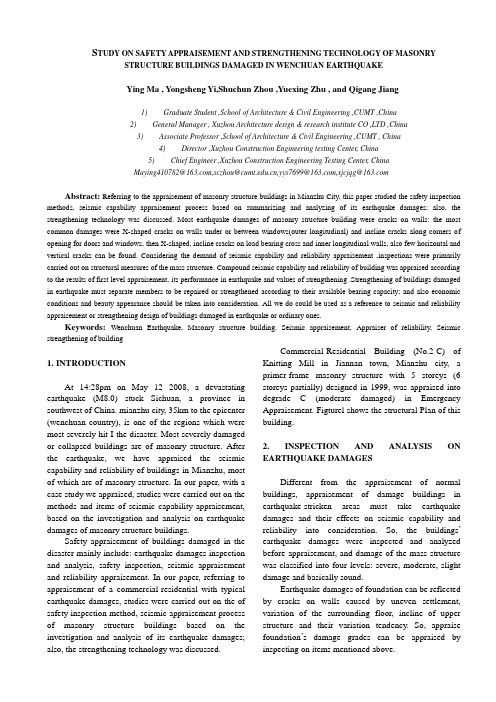
S TUDY ON SAFETY APPRAISEMENT AND STRENGTHENING TECHNOLOGY OF MASONRY STRUCTURE BUILDINGS DAMAGED IN WENCHUAN EARTHQUAKEYing Ma , Yongsheng Yi,Shuchun Zhou ,Yuexing Zhu , and Qigang Jiang1)Graduate Student ,School of Architecture & Civil Engineering ,CUMT ,China2)General Manager , Xuzhou Architecture design & research institute CO ,LTD ,China3)Associate Professor ,School of Architecture & Civil Engineering ,CUMT , China4)Director ,Xuzhou Construction Engineering testing Center, China5)Chief Engineer ,Xuzhou Construction Engineering Testing Center, China********************,***************.cn,***************,**************Abstract: Referring to the appraisement of masonry structure buildings in Mianzhu City, this paper studied the safety inspection methods, seismic capability appraisement process based on summarizing and analyzing of its earthquake damages; also, the strengthening technology was discussed. Most earthquake damages of masonry structure building were cracks on walls: the most common damages were X-shaped cracks on walls under or between windows(outer longitudinal) and incline cracks along corners of opening for doors and windows, then X-shaped, incline cracks on load bearing cross and inner longitudinal walls, also few horizontal and vertical cracks can be found. Considering the demand of seismic capability and reliability appraisement ,inspections were primarily carried out on structural measures of the mass structure. Compound seismic capability and reliability of building was appraised according to the results of first level appraisement, its performance in earthquake and values of strengthening .Strengthening of buildings damaged in earthquake must separate members to be repaired or strengthened according to their available bearing capacity; and also economic conditions and beauty appearance should be taken into consideration. All we do could be used as a reference to seismic and reliability appraisement or strengthening design of buildings damaged in earthquake or ordinary ones.Keywords:Wenchuan Earthquake, Masonry structure building, Seismic appraisement, Appraiser of reliability, Seismic strengthening of building1. INTRODUCTIONAt 14:28pm on May 12 2008, a devastating earthquake (M8.0) stuck Sichuan, a province in southwest of China. mianzhu city, 35km to the epicenter (wenchuan country), is one of the regions which were most severely hit I the disaster. Most severely damaged or collapsed buildings are of masonry structure. After the earthquake, we have appraised the seismic capability and reliability of buildings in Mianzhu, most of which are of masonry structure. In our paper, with a case study we appraised, studies were carried out on the methods and items of seismic capability appraisement, based on the investigation and analysis on earthquake damages of masonry structure buildings.Safety appraisement of buildings damaged in the disaster mainly include: earthquake damages inspection and analysis, safety inspection, seismic appraisement and reliability appraisement. In our paper, referring to appraisement of a commercial-residential with typical earthquake damages, studies were carried out on the of safety inspection method, seismic appraisement process of masonry structure buildings based on the investigation and analysis of its earthquake damages; also, the strengthening technology was discussed.Commercial-Residential Building (No.2-C) of Knitting Mill in Jiannan town, Mianzhu city, a primer-frame masonry structure with 5 storeys (6 storeys partially) designed in 1999, was appraised into degrade C (moderate damaged) in Emergency Appraisement. Figturel shows the structural Plan of this building.2. INSPECTION AND ANALYSIS ON EARTHQUAKE DAMAGESDifferent from the appraisement of normal buildings, appraisement of damage buildings in earthquake-stricken areas must take earthquake damages and their effects on seismic capability and reliability into consideration. So, the buildings’earthquake damages were inspected and analyzed before appraisement, and damage of the mass structure was classified into four levels: severe, moderate, slight damage and basically sound.Earthquake damages of foundation can be reflected by cracks on walls caused by uneven settlement, variation of the surrounding floor, incline of upper structure and their variation tendency. So, appraise foundation’s damage grades can be appraised by inspecting on items mentioned above.Fig.1 Ground plan of Commercial-Residential Building (NO.2-C) of Knitting Mill in Jiannan town,Mianzhu city(a) Ground Plan, and (b) Standard PlanDamage inspection of masonry structure building should focus on the following locations: four corners of the building, walls on the ground floor, walls of big room, load bearing walls, ring beams, structural columns, connection of walls, and so on.For example, we detected earthquake damages of Commercial-Residential Building (NO.2-C) of Knitting Mill in Jiannan town, Mianzhu city, and summarized as followings:(1) Uplift or depression of ground surrounding the building, cracks and difference of elevation between walls and its surrounding ground, disruption and depression of floor (the biggest depression measured is 68.9mm), differential settlement of mass structure (the difference of elevation measured at sides of expansion joint is 20.9mm) (Fig.2.a).(2) Horizontal shear failure or concrete crisped at the column capital on the ground floor (Fig.2.b).(3) Varying degree of incline, X-shaped, horizontal and vertical cracks on walls: severely cracked, distorted or even partial collapsed of outer longitudinal walls; and damages were severer from the top down.(4) No severe damages on ring beams or structural columns.(5) Obvious cracks along a few precast concrete panel joint (Fig.2.f).(7) Severe cracks on longitudinal walls on the ground floor of stair hall, vertical cracks on the string pieces (in the middle often), severe cracks on the parapet wall at the corner.Fig.2 show damages of Commercial-Residential Building (NO.2-C) of Knitting Mill in Jiannan town, Mianzhu city. Considering severe cracks on much more walls and obvious cracks of corners of longitudinal and cross walls, we appraised the damaged grade of Commercial-Residential Building (NO.2-C) of Knitting Mill in Jiannan town, Mianzhu city into moderate damage.Fig.2 Damages of Commercial-Residential Building (NO.2-C) of Knitting Mill in Jiannan town, Mianzhu city(a) Disruption and Depression of Floor Tiles in the Shops’ Doors. (b) Horizontal Shear Failure at the Column Capital. (c) X-Shaped Cracks on Walls under Windows. (d) Horizontal Cracks on Bearing Cross Walls. (e) Incline Cracks Along Corners of Opening for Doors, and (f) Horizontal Cracks Along A Few Precast Concrete Panel JointFrom the investigation of Commercial-ResidentialBuilding (NO.2-C) of Knitting Mill in Jiannan town, Mianzhu city and other masonry structure buildings, it can be conclude that the earthquake damages of masonry structure building mainly represented as follows.(1) Uplift or depression of ground surrounding, cracks and difference of elevation between walls and its surrounding ground can be found, when the building located in the field bad geological condition.(2) Severely destroyed of the mass structure; and damages of masonry structure were mostly centralized at the bottom 2~3 layers of buildings, four corners and the ground floor of building particularly. Also, partial collapsed walls can be found on the ground floor.(3) Most earthquake damages of masonry structure building were cracks on walls: the most common damages were X-shaped cracks on walls under or between windows (outer longitudinal) (Fig.2.c) and incline cracks corners along corners opening for doors or windows (Fig.2.e); then X-shaped, incline cracks on load bearing cross walls and inner longitudinal walls, also few horizontal and vertical cracks can be found (Fig.2.d).(4) Cracks were easily produced on cross walls at the connection of walls.(5) Played their roles of tying walls up, seldom ring beams and structural columns were severely destroyed.(6) Horizontal cracks along a few precast concrete panel joint can be found because of bad concreteness led by using of precast concrete slab.(7) Damages were severer from the top down.(8) Designed and built according technical code strictly, buildings newly built performed more excellently than the past which may had not been designed at all.3. SAFETY INSPECTIONConsidering the demand of seismic capability and reliability appraisement, the inspections were primarily carried out on structural measures of whole structure and materials’ strength. The inspection contents can be interpreted from inspection of Commercial-Residential Building (NO.2-C) of Knitting Mill in Jiannan town, Mianzhu city following:(1) The building used primer-frame masonry structure and precast concrete panels, and it used cross walls to bear load. The U-shaped plane from was cut into two rectangle by expansion joint, so the structure plane from can be considered as two rectangles.(2) Five storeys altogether (six storeys partially) and 3m high for each storey, the building is 16.2m high (eaves height, 19.2m partially).(3) Its load-bearing walls (cross walls) were masonry by fired common bricks (240mm), and the maximum space between windows and other partial dimensions can satisfy the requirement of technical code.(4) The strength of mortar for brick inspected can not satisfy the demand of design, which is M7.5 (the first and second floor) and M5 (other floors). And the strength of bricks designed was MU10.(5) Structural columns were erected at corners of outer walls, once every other intersection of cross walls and outer walls, each corner of stairwell, and both sides of big openings for doors or windows. Ring beams were erected every floor. The sectional dimension and ring beams are both 240*240mm2/4Φ12. The Compressive strength of Structural columns and Ring beams can satisfy the demand of design.(6) 2Φ6 tie bats were assembled every 500mm from top to bottom of walls.(7) The maximum displacement of mass structure was 8.6mm, while the maximum storey displacement was 5.2mm.(8) The damages of ring beams and structuralcolumns were not so obvious. But damages on seismic cross walls and connections of walls were found which affect the seismic capacity and reliability of buildings.4. SEISMIC APPRAISEMENTWhen we appraised buildings damaged in Wenchuan Earthquake, we should follow the provisions of Technical guidelines for appraisement and strengthening of building after earthquake ([2008]132 by MOHURD) and technical specification for seismic appraisement and strengthening of building in Sichuan province (DB51/D5059-2008). The appraisement process of Commercial-Residential Building (NO.2-C) of Knitting Mill in Jiannan town, Mianzhu city is as followings:(1) Though uplift or depression of ground surrounding, but the incline of upper structure was not so serious (maximum displacement of mass structure was 8.6mm) and there was no evidence of development. All of these indicate that it has no serious static defect and can satisfy the requirements of seismic appraisement.(2) The structure system, plan and elevation form, maximum height of storey and mass structure, maximum number of layers, maximum space between cross walls, partial dimensions (maximum width of walls between opening for doors or windows), erection of ring beams and structural columns, and fastenings and connections of accessory and main structure all can satisfy the requirements of seismic appraisement.(3) Affecting the seismic capacity of walls and mass structure, available seismic capacity of several seismic cross walls severe cracked and connections of walls slacked can not satisfy the requirements of seismic appraisement. Available seismic capacity of other walls not cracked can satisfy the requirements of seismic appraisement.(4) According to items appraised above and DB51/D5059-2008, it can be appraised that the available compound seismic capacity of the building can not satisfy the requirements of seismic appraisement considering its performance in the earthquake. But as it experienced the massive earthquake in Wenchuan and met the demand of “not collapse when macro-quake happens”, the building has its value to be strengthened.By referring to seismic appraisement of Commercial-Residential Building (NO.2-C) of Knitting Mill in Jiannan town, Mianzhu city and others, seismic appraisement methods can be concluded. In seismic appraisement, the compound seismic capacity of the mass structure should be appraised according to walls’available capacity and the results of the first level seismic appraisement, in which macro-control and details of seismic design were mainly appraised; also, its real performance in the earthquake should be taken into consideration. Actually, the appraisal principle above conformed to the technical specification DB51/D5059-2008.Determination of walls’available capacity is the most important process in seismic appraisement of building. Walls’available seismic capacity can be determined mainly referring to its performance and damage level in the earthquake. It can be considered that walls lost most of their bearing capacity and had very poor available seismic capability when severe damages (oversized cracks) were found on them. But available seismic capability of walls with few damages should be determined by their damages, strength of brick and mortar, and so on.Items of the first level seismic appraisement could be appraised by simple calculation or directly compared to standards.5. RELIABILITY APPRAISEMENTBased on its earthquake damages and the results of seismic appraisement building’s reliability was appraised according to Standard for appraiser of reliability of civil buildings (GB50292-1999).Considering the damage characteristics, the reliability of masonry structure building was appraised mainly according to the earthquake effects to its safety and usability. For example, safety appraisement of wall members was mainly referred to their crack grades and damages at the connection. But mass structure was appraised at a macroscopic level, taking damage grade and position, seismic concept design, details of seismic design of mass structure into consideration. The appraisement concept can be interpreted from the appraisement process of Commercial-Residential Building (NO.2-C) of Knitting Mill in Jiannan town, Mianzhu city following:(1) Dividing the building into three levels: member sub-system, and appraisement system.(2) Considering it has no serious static defect, but slight differential settlements, the safety of building foundation (sub-system) was appraised as degrade B u, usability degrade B s and reliability degrade B.(3) Because of their poor available capacity cause by severely cracks, the safety of most wall members onthe ground and first floors were appraised as degrade C u, but most wall members on the above floors were appraised as degrade B u. Safety of superstructure (sub-system) can be appraised as degrade C u, usability degrade C s (because damages effect on usability was so obvious) and reliability degrade C.(4) The safety of accessory structure (sub-system) can be appraised as degrade B u, usability degrade B s and reliability degrade B, because of damages of stairwell and other accessory structures.(5) According to items appraised above and GB50292-1999,it was appraised that safety degrade of the building is D su, usability C ss and reliability Ⅳ, taking its performance in the earthquake in to consideration. The bearing capacity and usability of the building was severely affected by earthquake, and should be enhanced.6. REPAIR AND STRENGTHENING TECHNOLOGYStrengthened value should be evaluated before design: because of severe cracks on walls or even partial collapse and not so high quality of design and construction, there are poor strengthening values for severely destroyed buildings; but high strengthened value for moderate damaged ones, as they experienced the massive earthquake in Wenchuan and (or even exceed) the demand of “not collapse when macro-quake happens”.When strengthening a building damaged in earthquake, member must be separated into be repaired or strengthening according to their available bearing capacity, taking economic consideration and beautiful appearance should into consideration. Following the principle that pay equal attention to repair, strengthening and long-term maintenance, strengthening should radically improve the aspects which are to the according to damage reasons and results of inspection and appraisement.The suggestions for Commercial-Residential Building (NO.2-C) of Knitting Mill in Jiannan town, Mianzhu city are as following:(1) There is high strengthening value of the building, as it experienced the massive earthquake in Wenchuan and met the demand of “not collapse when macro-quake happens”because of its comprehensive details of seismic design for mass structure.(2) Rebuilding walls severely destroyed, such as longitudinal walls on the bottom two floors of stair-hall. Using masonry strengthening with piaster splity or concrete splity on both sides of walls to strengthening walls which were severely cracked (or over sized cracks were found), after cracks pointed and repaired with polymer mortar. And for members who can satisfy the demand of safety but usability, only repairing measures such as surface retrowelling and crack pouring are OK.(3) Casting a concrete layer (about 50mm) on the precast concrete slab or erect steel tie bar under the slab, to enhance its monolith.From the suggestion it can be conclude that structural measures of mass structure and strength of materials are aspects which affect the seismic capacity and reliability, and strengthening of masonry should start from the two aspects. Masonry structure buildings in Mianzhu city usually use precast concrete slab which is bad for its monolith and can be improved by casting a concrete layer (about 50mm) on or erect steel tie bar under the slab. Take different strengthen method for different members separated by available bearing capacity, only simple repair for slight damaged members while masonry strengthening with plaster splity or concrete splity on both sides of walls for severely damaged members.Alternatively, they could be strengthened by energy dissipation technology or seismic isolation technology.7. CONCLUSIONS AND SUGGESTIONS(1) One of the biggest difference between seismic capability and reliability appraisement of damaged building in earthquake-stricken areas is Different standard for appraisement. Because of the large number, different construction time and its private property right of the damaged building, it should be allowed to appraise building according to the original design standards on the precondition that there’s no harm to public security.(2) Another difference between seismic capability and reliability appraisement of damaged buildings in earthquake-stricken areas is the latter appraisement must take effects of earthquake damages into consideration and mainly include: earthquake damages inspection and analysis, safety inspection, seismic appraisement and reliability appraisement.(3) Earthquake damages of masonry structure building were mostly cracks on walls: X-shaped cracks on walls under or between windows (outer longitudinal), include cracks along corners of opening for doors or windows, X-shaped, include cracks on load bearing cross walls and inner longitudinal walls, and also fewhorizontal and vertical cracks. Mostly centralized at the bottom 2-3 layers of buildings, earthquake damages of masonry structure were severer from the top down. Buildings newly designed performed excellently in the disaster, because of its comprehensive details of seismic design for mass structure.(4) Safety inspection should be carried out on structural features of mass structure, connections, and materials’strength. Also earthquake effects on the inspection items should be analyzed.(5) The compound seismic capability of the mass structure should be appraised according to walls’available capacity and the results of the first level seismic appraisement. Walls’ available seismic capacity can be determined mainly referring to its performance and damage level in the earthquake.(6) Reliability was appraised mainly according to the earthquake effects to its safety and usability.(7)Strengthened value should be evaluated before design: moderate damaged buildings had high strengthening value, but severely destroyed ones had not. A good strengthening design of a buildings damaged in earthquake should separate member into be repaired or strengthening according to their available bearing capacity, pay equal attention to repair, strengthening and long-term maintenance, and radically improve the aspects which are to the disadvantages of seismic capability and reliability. For masonry structure, we suggest starting from structural measures of mass structure and strength of materials, and separating member into to be repaired or be strengthening ones.(8) The building with compound or masonry structure were severely destroyed in Wenchuan Earthquake, and seismic deficiencies were revealed a lot. But lots of buildings with such structure exist in our country. Their seismic capacities are so poor that must enhanced as quickly as possible. So, research on strengthening of masonry or compound structure should be paid enough attention to.References:[1] Xuzhou Construction Engineering Testing Center.(2008), “Report of Safety Appraisement: Commercial-Residential Building (NO.2.C) of knitting Mill in jiannan town, Mianzhu city (XJD2008007)”.[2] MOHURD. (2008) “Technical guidelines for appraisement and strengthening of building after earthquake ([2008]132)”.[3] Department of Construction of Sichuan province. (2008), “Technical specification for seismic appraisement and strengthening of building in Sichuan province (DB51/D5059-2008)”.[4] Ministry of Construction of China. (1995) “Standard for seismic appraiser of building (GB50023-95)”, China Architecture & Building Press.[5] Ministry of Construction of China. (1999) “Standard for appraiser of reliability of civil buildings (GB50292-1999)”, China Architecture & Building Press.[6] MOHURD. (2008) “Code for seismic design of buildings (GB50011-2001)”, China Architecture & Building Press.。

混凝土结构抗震性能检测方法一、引言混凝土结构是建筑工程中常见的结构形式,其在抗震性能方面的检测至关重要。
本文将从混凝土结构抗震性能检测的目的、基本原理、检测方法和注意事项等方面进行详细介绍。
二、目的混凝土结构抗震性能检测的目的是评估建筑物在地震作用下的安全性能,为建筑结构的加固和改造提供依据。
三、基本原理混凝土结构的抗震性能主要与其结构的强度、刚度、耐久性以及连接件的可靠性等因素有关。
因此,在进行抗震性能检测时,需对混凝土结构的这些因素进行综合评估。
四、检测方法1.现场检测现场检测是混凝土结构抗震性能检测的主要手段之一。
现场检测的方法主要包括:(1)视觉检测:通过目视观察混凝土结构是否存在裂缝、变形等问题,评估结构的稳定性和安全性能。
(2)声波检测:通过在混凝土结构表面敲击或振动,利用声波传播的速度和振幅等参数,评估结构的强度和耐久性。
(3)钻孔取芯:通过在混凝土结构中钻取样品,对其进行化学分析和物理试验,评估结构的力学性能和材料性能。
2.试验室检测试验室检测是混凝土结构抗震性能检测的另一种重要手段。
试验室检测的方法主要包括:(1)压缩试验:通过在试验室中对混凝土试块进行压缩试验,评估其强度和刚度等力学性能。
(2)弯曲试验:通过在试验室中对混凝土梁进行弯曲试验,评估其强度和刚度等力学性能。
(3)剪切试验:通过在试验室中对混凝土试块进行剪切试验,评估其强度和刚度等力学性能。
(4)动力试验:通过在试验室中对混凝土结构进行振动试验,评估其振动特性和耐震性能。
五、注意事项在进行混凝土结构抗震性能检测时,需要注意以下事项:1.检测前需做好周边环境的安全防护措施,防止人员和设备受到伤害。
2.检测前需对检测设备进行严格的校验和检测,确保其精度和可靠性。
3.检测过程中需按照相关标准和规范进行操作,保证检测数据的准确性和可比性。
4.检测后需对检测数据进行合理的分析和处理,得出正确的结论和评估结论。
5.检测结果需及时向相关部门和业主报告,为加固和改造提供依据。
一个未完工的二层预制混凝土结构物的抗震测试这篇文章是关于地震和预制混凝土建筑物设计的试验性的研究。
墨西哥市里一个带有双重系统和代表了一个停车场结构的未完工的两层的预制混凝土建筑物被调查研究。
这个结构物在实验室里用模拟地震荷载测试,结果失败了。
在一些梁和柱的接头处,粱底部的纵筋由于尺寸的限制不能屈服。
这项研究所强调的是提高所测试结构物的可观察的综合性能。
这种性能表现为所测试结构物的墙控制传力途径而且能显著地减少预制结构所要求的侧向变形。
源自于这项研究的预制混凝土结构抗震设计标准和规范细节被讨论。
这项研究的最终结果是能更好地理解这种类型的建筑物的已得知的性能。
在墨西哥,一个两层的预制混凝土构件建成的预制混凝土建筑物,在其上加上模拟的地震荷载。
在这里描述的是其结果。
在测试结构物中所选择的结构系统是所谓的双重类型,其定义就是构造墙的结合点以及梁-柱框架。
测试结构物中预制梁柱之间的结合是窗型的。
这种类型的建设显著地用在低的或中等高建筑物中,在这种建筑中在每一楼层中柱子和窗子连在一起。
这些“窗”包含顶部和底部的钢筋。
图1所示的是在墨西哥市中这种类型的一个商业建筑物。
大多数的预制混凝土结构如图1中所示,纵梁底部的钢筋不能完全屈服。
这是由于在梁-柱接头中柱的尺寸限制所造成的。
为了尽力克服这种缺陷,正如在后面所描述的,在墨西哥一些工程师尝试着这样设计这些接头,就是通过用箍筋圈住这些钢筋,这样做是为了达到所要求的连续性。
然而,这种尝试在ACI建筑规范和MCBC中都没有提到。
这些研究的一部分是为了阐述这个观点。
这项研究的目的是为了提高在实验室里的预制混凝土结构屋的可观察的性能以及为利用谕旨构件或预制结构建议了一个可接受的期望的抗震性能以及从建设能力的观点所得出的有吸引力的特征。
这篇文章中强调的所测试结构物中预制构件间的连接处的可观察的性能以及预制楼层系统的性能将会详细讲述。
在过去的地震中,在建筑物中造成的可观察的构造和非构造的破坏显示了通过控制结构的侧向位移来降低由地震造成的建筑物的破坏的重要性。
混凝土框架结构预制构件抗震性能检测技术规程一、前言混凝土框架结构预制构件是现代建筑中常用的结构形式,其具有工程造价低、建造速度快等优点,但在地震灾害发生时,也会受到一定的影响。
因此,为了保证混凝土框架结构预制构件的抗震性能,需要进行相关的检测工作。
本文将介绍混凝土框架结构预制构件抗震性能检测技术规程。
二、检测目的本技术规程的检测目的是评估混凝土框架结构预制构件的抗震性能,包括抗震能力、变形能力和耗能能力,并根据检测结果制定相应的加固措施。
三、检测内容1.检测前准备(1)确定检测对象:根据施工图纸和实际情况,确定待检测的混凝土框架结构预制构件。
(2)检测设备:准备检测设备,包括震动台、振动传感器、加速度计、位移传感器等。
(3)检测人员:确保检测人员具有相关的专业技能和经验。
2.试验方案设计(1)试验类型:根据待检测的混凝土框架结构预制构件的结构特点和实际使用情况,选择相应的试验类型,如静力试验、动力试验等。
(2)试验参数:根据试验类型和待检测的混凝土框架结构预制构件的特点,确定试验参数,如地震波参数、试验频率、振动幅度等。
(3)试验方案:根据试验类型和试验参数,设计试验方案,包括试验步骤、试验装置设置、试验数据采集等。
3.试验执行(1)试验前检查:对试验设备进行检查和调试,确保试验正常进行。
(2)试验过程:按照试验方案进行试验,采集试验数据。
(3)试验结果:对试验数据进行分析和处理,得出试验结果。
4.试验结果分析(1)试验数据处理:对试验数据进行处理,包括数据滤波、数据修正、数据统计等。
(2)试验结果分析:根据试验数据分析试件的抗震能力、变形能力和耗能能力,并评估试件的抗震性能。
5.结论和建议(1)结论:根据试验结果,对待检测的混凝土框架结构预制构件的抗震性能进行评估,得出结论。
(2)建议:根据结论,制定相应的加固措施和改进方案,提高混凝土框架结构预制构件的抗震性能。
四、检测要点1.试验设备:试验设备应符合国家标准,并经过检测和校准。
对汶川地震中受损的砖瓦结构建筑物的安全评估及加固技术的研究马英易永生周树春朱岳兴蒋启刚1)中国矿业大学建筑及土木工程学院毕业生2)中国徐州建筑设计研究院有限公司总经理3)中国矿业大学建筑及土木工程学院副教授4)中国徐州建筑工程测试中心主任5)中国徐州建筑工程测试中心首席工程师Maying410782@,sczhou@,yys7699@,xjcjqg@[摘要]:本文将参照对绵竹的砖瓦结构建筑物的评估,总结分析其地震伤害,来研究安全检查方法,地震等级评估流程;同时,加固技术也在讨论范围之内。
绝大部分地震造成的砖瓦结构建筑物的损伤都体现为墙体的断裂:最常见的墙体断裂是窗子下面或窗子(外纵向)之间的X形断裂及门窗开口角落的斜向X形断裂,以及承重横墙及内纵墙体的斜向X形断裂,也有部分水平或垂直断裂。
考虑到地震等级及可靠性的评估需求,检查主要从对大量建筑的结构措施着手。
建筑物抗震能力及可靠性综合评估参照第一等级的评估结果,即其在地震中的表现和加固水准的表现。
加固建筑物在地震中的损伤分为修复后的或者根据其承载能力加固之后的;同时经济条件及外观也在考虑范围之内。
我们所做的可作为地震及可靠性评估或者加固设计建筑物在地震中的损失或者平常建筑物在地震中的损失之参考。
[关键词]:汶川地震,砖瓦结构建筑物,地震评估,可靠性评估,建筑物抗震加固。
1 简介2008年5月12日 14:28分,一场毁灭性的8级地震袭击了中国西南部省份四川省绵竹市,震中为距此35km的汶川县,是此次灾难损失最严重的地区之一。
绝大部分严重损伤或倒塌的建筑物均为砖瓦结构。
震后,我们对绵竹建筑物的抗震能力及可靠性进行了评估,其中绝大部分均为砖瓦结构建筑物。
在我们的报告中,我们将研究个案,结果均出自抗震评估的方法及项目,以地震中受损的砖瓦结构建筑物的调查分析为基本。
灾难中的受损建筑物安全等级评估主要包括:地震损失的检查及分析,安全检查,震级评估及可靠性评估。
Tests on a Half-Scale Two-Story Seismic-Resisting Precast Concrete BuildingThis paper describes experimental studies on the seismic behavior and design of precast concrete buildings. A half-scale two-story precast concrete building incorporating a dual system and representing a parking structure in Mexico City was investigated. The structure was tested up to failure in a laboratory under simulated seismic loading. In some of the beam-to-column joints, the bottom longitudinal bars of the beam were purposely undeveloped due to dimensional constraints.Emphasis is given in the study on the evaluation of the observed global behavior of the test structure. This behavior showed that the walls of the test structure controlled the force path mechanism and significantly reduced the lateral deformation demands in the precast frames. Seismic design criteria and code implications for precast concrete structures resulting from this research are discussed.The end result of this research is that a better understanding of the structural behavior of this type of building has been gained results of simulated seismic load tests of a two story precast concrete building constructed with precast concrete elements that are used in Mexico are described herein. The structural system chosen in the test structure is the so called dual type, defined as the combination of structural walls and beam-to-column frames. Connections between precast beams and columns in the test structure are of the "window" type. This type of construction is typically used in low- and medium rise buildings in which columns are connected with "windows" at each story level. These "windows" contain the top and bottom reinforcement. Fig. 1 shows this type of construction for a commercial building in Mexico City.In most precast concrete frames such as those shown in Fig, 1, longitudinal beam bottom bars are not fully developed due to constraints imposed by the dimensions of file columns in beam-to-column joints. In an effort to overcome this deficiency, and as described later, some practicing engineers in Mexico design these joints by providing hoops around the hooks of that reinforcement in order to achieve its required continuity. However, this practice is not covered in the ACI Building Code(ACI318-02), nor in the Mexico City Building Code (MCBC, 1993). Part of this research was done to address this issue.The objectives of this research were Io evaluate the observed behavior of a precast concrete structures in the laboratory and to propose the use of precast structural elements or precast structures with both an acceptable level of expected seismic performance and appealing features from the viewpoint of construction Emphasis is given in this paper on the global behavior of the test structure. In the second part of this research which gill be presented in a companion paper, the observed behavior of connections between precast elements in the test structure, as well as the behavior of the precast floor system will be discussed in detail.Structural and non structural damages observed in buildings during past earthquakes throughout the world have shown the importance of controlling lateral displacement in structures to reduce building damage during earth- quakes. It is also relevant to mention that there are several cases of structures in moderate earthquakes in which the observed damage in non-structural elements in buildings was considerable even though the structural elements showed little or no damage. This behavior is also related Io excessive lateral displacement demands in the structure.To minimize seismic damage during earthquakes, the above discussion suggests the convenience of using a structural system capable of controlling lateral displacements in structures. A solution of this type is the so-called dual system. Studies by Paulay and Priestley4 on the seismic response of dual systems have shown that the presence of walls reduce the dynamic moment demands in structural elements in the frame subsystem. Also in conjunction with shake table tests conducted on a cast-in-place reinforced concrete dual system. Bertero5 has shown the potential of the dual system, in achieving excellent seismic behavior [n this investigation, the dual system is applied to the case of precast concrete structures.DUCTILITY DEMAND IN DUAL SYSTEMSIn order to develop a base for a later analysis of the observed seismic response of the test structure studied in this project a simple analytical model is used to evaluate the main features of ductility demands in dual systems.Fig 2 shows the results of a simple approach to analyze the lateral load response iii a dual system. The lateral load has been normalized in such a manner that the combination of maximum lateral resistance in both subsystern i.e. walls and frames--leads to a lateral resistance of the global system equal to unity b is also assumed that both subsystems have the same maximum lateral resistance. In the first case (Fig 2a), it is assumed that the wall and frame subsystems have global displacement ductility capacities equal to 4 and 2 respectively. In the second case (Fig. 2b), the frame subsystem response is assumed to be elastic, and the lateral stiffness of the wall subsystem is taken to be 4 times that of the frame subsystem.As shown in Fig 2, the lateral deformation compatibility of the combined system is controlled by the lateral deformation capacity of the wall subsystem. In the first case Fig 2ak an elastic-plastic envelope for the lateral global response of the dual system is assumed, and the corresponding displacement ductility (u) is equal to 33.For the second case (Fig. 2b) with an elastic behavior of the frame subsystem, this ductility is equal to 25.These simple examples illustrate that in the analyzed cases, due to the higher flexibility in the frame subsystems as compared to those of the wall subsystern, in a dual system, the ductility demands in the frame subsystem result in smaller ductility values than those of the wall subsystem. This analytical finding was verified in this study from the experimental studies conducted on the test structure. This verification is later discussed in the paper It is of interest to note that results of the type shown in Fig. 2 have been also found by Bertero' in shake table tests of a dual system. DESCRIPTION OF TEST STRUCTUREThe test structure used in this investigation is a two-story precast concrete building, representative of a low-rise parking structure located in the highest seismic zone of Mexico City. The prototype was constructed at one-half scale. For the sake of simplicity, ramps required in a parking structure have not been considered in the selected prototype structure. Their use, requiring large openings in the floor system, would have required a very complex model of the floor system for both linear and nonlinear analysis of the structure.A detailed description of the dimensions, materials, design procedures, and construction of the test structure can be found elsewhere.6 A summary of this information is given below.The dimensions and some characteristics of the test structure are shown in Fig. 3. The longitudinal and transverse are shown in Fig3a. Also, the exterior (longitudinal) frame containing the wall (Column Lines 1 and 3) are termed the lateral frame (see Fig, 3b), and the internal (longitudinal) frame with the single tee (Column Line 2) are termed the central frame.Doable tees spanning in the longitudinal direction are supported by L-shaped precast beams in the transverse direction as shown in Fig3a. The structure uses precast frames and precast structural walls, the latter elements functioning as the main lateral load resisting system. Fig. 4 shows an early phase of the construction of the test structure. As can be seen, the "windows'' in the columns and walls are left in these elements for a later assemblage with the precast beams.The unfastened design base shear required by the Mexico City Building Code (MCBC, 1993)2 is 0.2WT, where WT is the total weight of the prototype structure, assuming a dead load of 5,15 KPa (108 psi) and a live load of 0.98 KPa (20.5 psi). The prototype structure was designed using procedures of elastic analyses and proportioning requirements of the MCBC, In these analyses, the gross moment of inertia of the members in the structure was considered and rigid offsets (distances from the joints to the face of the supports) were assumed for all beams in the structure except for beams in the central frame, which had substandard detailing as will be described latch.Results from these analyses indicated that the structural walls in the test structure would take about 65 percent of the design lateral loads. A review of the nominal lateral resistance of the structure using the MCBC procedures showed that this resisting force was about 1.3 times the required code lateral resistance (0,2Wr), This is one of several factors, later discussed, that contributed to the over-strength of the structure.The longitudinal reinforcement in all the structural elements of the test structorewas deformed bars from Grade 420 steel. Table 1 lists the concrete compressive cylinder strengths for different members of the prototype structure. Fig. 5 shows typical reinforcing details for precast beams spanning in the direction of the applied lateral load (see Fig. 3).Figs. 6 and 7 show reinforcing details for the columns, and for the structural wails and their foundation, respectively. It should be mentioned that the test structure was designed with the requirements for moderately ductile structures specified by the MCBC. According to these provisions, the test structure did not require special structural walls with boundary elements such as those specified in Chapter 21 of AC1 318 02.The precast two-story columns were connected to the precast foundation by unthreading them in a grouted socket type connection. The reinforcing details of the foundation, as well as its design procedure and behavior in the test structure are discussed in the companion paper? Tae beam-to-cadmium joints in file test structure were cast-in-place to enable positioning the longitudinal reinforcement of the framing beams. The beam top reinforcement was placed in sum on top of the precast beams. Fig. 8 shows typical reinforcing details for the joints in the double tees of the central frame. Since these tees and their supporting L-shaped beams in Axes A or C (see Fig.3) had the same depth, the hooked bottom longitudinal bars in the double tees could not pass through the full depth of the column because of interference with the bottom bars from file transverse beam (see Fig. g).As a result, these hooked bars possessed only about 55 percent of the development length required by Chapter 21 of ACI 318-02. In an attempt to anchor these hooked bars, some designers in Mexico provide closed hoops around the hooks, as shown in Fig. 8. The effectiveness of this approach was also studied in the companion paper.3 Beam to-column joints in the lateral frames of the test structure had transverse beams that were deeper than the longitudinal beams. This made it possible for the top and bottom bars of the longitudinal beams to pass through the full joint, and, therefore, these bars achieved their required development length.Cast-in-place topping slabs in the test structure were 30 mm (1.18 in.) thick andformed the diaphragms in January-February 2005 Fig. 3. Plan and elevation of test structure: (a) Plan; (b) Lateral frame; (c) Transverse frame. Dimensions in mm. Note: 1 mm - 0.0394 in. the structural system. Welded wire reinforcement (WWR) was used as reinforcement for the topping slabs. The amount of WWR ill the topping slabs was controlled by the temperature and shrinkage provisions of the MCBC. which are similar to those of AC[ 318-02.It is of interest to mention that the requirements for shear strength in the diaphragms given by these provisions, which are similar to those of ACI 318-89, did not control the design. A wire size of 6 x 6 in. 10/10 led to a reinforcing ratio of 0.002 in the topping slab. The strength of the WWR at yield and fracture obtained from tests were 400 and 720 MPa(58 and 104 ksi),respectively.TEST PROGRAM AND INSTRUMENTATIONTest ProgramThe test structure was subjected to simulate seismic loading in the longitudinal direction (see Fig. 3a). Quasitatic cyclic lateral loads FI and F2 were applied at the first and second levels of the structure, respectively (see Fig. 3b). The ratio of F2 to FI was held constant throughout the test., with a value equal to 2.0. This ratio represents an inverted triangular distribution of loads, which is consistent with the assumptions of most seismic codes including the MCBC.The test setup is shown in Fig. 9.The structure had Hinges A, B, and Cat each slab level as shown in Fig. 9b.The purpose of the hinges was to avoid unrealistic restrictions in the structure by allowing the ends of the slabs to rotate freely during lateral load testing. As can be seen in Fig 9, the lateral loads were applied by hydraulic actuators that work in either tension or compression.When the actuators worked in compression, they applied the loads directly at one side of the structure. However, when the actuators applied tensile loads at one side of the test structure, they were convened to compression loads at the other side by means of four high strength reinforcing bars for each actuator [see D32 ((~1~ in) reinforcing bars in Fig. 9]. Both ends of these bars were attached to 50 mm (2 in.) thick steel plates At each of the floor levels, two of these plates were part of Hinge A, and theother two plates at the actuator side were part of Hinge B (see Fig. 9b).As can be seen in Fig 9b before the application of tensile loads in the actuators, the latter end of the plates left a clear space with the end of the slab. This space at zero lateral load was about 50 mm (2 in.), and it allowed for beam elongation of the structure which occurs during the formation of plastic hinges in the beams? For the case of compressive loads on the actuators acting on the transverse beam at the side of Hinge B (see Fig. 9b), the system also allowed 50 mm (2 in.) of beam elongation. These particular features of the test setup allowed the application of compressive loads at points in the slabs with no special reinforcement at these points. If tensile forces had been applied to loading points in the slabs, it is very likely that these loading points would have required unrealistic, special reinforcing details that are not represent five of those in an actual structure.The gravity load was represented by 53 steel ingots, acting at each level of the structure, with the layout shown in Fig. 9a, The weight per unit area of the ingots per level was 2.79 KPa (58.3 psf), which added to the self-weight of tile slab, leading to a total floor dead load of 5.37 KPa (112 psf). This is 88 percent of the code required gravity load for seismic design (MCBC, 1993). It was not possible to apply the remaining 12 percent of gravity load due to space limitations in the slabs. The total weight of the structure, omitting the weight of the foundation, was 284.2 KN (63.9 kips).Transverse displacements in the structure (perpendicular to the loading direction) were precluded by using steel ball hearings installed in the lateral faces of beam to-column joints of the second level at Column Lines A1and A3 (see Fig. 9a). These ball bearings were supported by a steel frame. As shown in Fig. 10, the precast columns and wails were fixed to the strong floor using steel beams supported by the foundation and anchored to the floor. The lateral loading history used in the test structure was based on force control during elastic response of the structure, followed by displacement control during yield fluctuations, using the lateral roof displacement of the structure A.The target lateral load or top displacement was typically reached by incrementalloading of both actuators in which the bottom actuator was fore-contrived to half the load value of the top actuator. A cycle of lateral load of about 0.75Vg was initially applied, where VR is the nominal theoretical base shear strength computed using the ACI 318 02 provisions. The value of VR, 198 KN (44.5 kips), can be assumed to correspond to first yield in the structure.This parameter was computed using measured material properties, a strength reduction factor (1) equal to unity and common assumptions for flexural strength of reinforced concrete sections. For the lateral force of 0.75VR, the corresponding lateral roof displacement was defined as 0.75▽y’.Using this value and assuming elastic behavior, the calculated value of the displacement at first yielding, Ny, was equal to 4.5 mm (0.18 in.).After the cycle at 0.75▽y’, the structure was subjected to three cycles for each of the maximum prescribed roof displacements 2▽y’, 4▽y’, 6▽y’, 13▽y’ and 20▽y’--which correspond to roof drift ratios, Dr, of 0.003, 0.006, 0.009, 0.020 and0.031, respectively. The roof drift ratio can be defined as: Dr=A/H (1) whereH is the height of the structure measured from the fixed ends of first story columns. This value is equal to 2920 nun (115 in.).The complete cyclic lateral loading history applied to the structure is shown in Fig. 11. This loading history is expressed in terms of both displacement ductility, A/Ny, and roof drift ratio, Dr. In addition, the peaks of lateral displacements in Fig. 11 are related to the measured base shear force, V, expressed as the ratio V/VR.InstrumentationA detailed description of the instrumentation of the structure can be found in the report by Rodriguez and Blandon? Lateral displacements of the structure were measured with linear potentiometers placed at each level of the structure as shown in Fig. 12. Beam elongation, discussed later, was evaluated from measurements using this instrumentation. Twelve pairs of potentiometers were used for measuring the average curvatures in critical sections of two columns of the structure. In addition, nine pairs of potentiometers were instrumented in vertical sections of beams in central and lateral frames, and in sections of a wall base.Electrical resistance strain gauges were placed in the longitudinal reinforcement of some beams, columns and wails of the test structure, as well as in the hoops of beam to-column joints with substandard reinforcing details. Some of the measurements from this instrumentation and from the potentiometers in the beams are discussed in the companion paper. Here, the observed experimental response of the beam to-column joints with substandard reinforcing details is evaluated. EXPERIMENTAL RESULTSThe applied lateral loading history in the test structure is shown again in Fig.13. in this case, the peaks of lateral displacement are related to the most important events observed during testing, such as first yielding of the longitudinal reinforcement, first cracking in walls and topping slabs, loss of concrete cover, and buckling of longitudinal reinforcement.Fig. 14 shows the measured base shear force, V, versus roof drift ratio hysteretic loops. The ordinate of this graph represents the measured base shear expressed in a dimensionless form as the ratio V/VR. As shown in Fig. 14a, first yielding of the longitudinal reinforcement occurred at wails in the critical sections at foundation faces, at a roof drift ratio of about 0.0030, corresponding t9 a base shear force equal to about 1.4VR. The maximum measured base shear was equal to 549KN(123.4 kips) or 2.77VR, corresponding to a roof drift ratio of 0.020.Fig. 14b shows envelopes of interstory drift ratio, dr, measured during testing in the two levels of the structure. The results show that the two levels had similar values of interstory drifts, which is due to the significant contribution of the structural walls to the global response of the structure. This feature of the displacement profile of the structure suggests that for a given Dr Value, interstory drift values would be similar in magnitude.Cyclic lateral loading was terminated at a roof drift ratio of 0.034 corresponding to a base shear force of 462KN (103.8 kips) or 2.3Vn. At this level of lateral displacement, the buckling of longitudinal reinforcement at the fixed ends of the first-story walls was excessive, and it led to significant out-of-plane displacements of the walls along with wide cracks in the topping slab-to-wall joints as discussed in thecompanion paper? Fig. 14a also shows some of the most important events observed during testing. A summary of relevant damage observed during testing of die structure is described below.Wall damage was initiated by the loss of concrete cover and buckling of longitudinal reinforcement at the fixed ends of the first-story walls. These events occurred at a D, value equal to about 0.020. Buckling of the longitudinal reinforcement occurred immediately after the loss of concrete cover in these critical sections.Figs. 15 and 16 illustrate the cracking pattern and damage observed at the end of testing for the lateral frame and for the central frame, respectively. Fig. 17 shows an overall view of the damage of the lateral frame at file end of testing, and Fig. 18 provides a closer look at the buckling of longitudinal reinforcement at the fixed end of a first-story wall at the end of testing. Figs. 15 through 18 indicate that the observed damage at the end of testing in the columns and beams to-column, and beam column joints was significantly less than that of the walls.The formation of plastic hinges in the critical sections of the structural elements, such as at the fixed ends of the first story columns and wails, and in beam ends at wall faces, was observed during testing, especially after reaching the maximum base shear.Evidence of buckling of the longitudinal reinforcement was also observed in some of these sections of columns and beams (see Figs. 15 and 16), foremen of some beams, columns and wails of the test structure, as well as in the hoops of beam to-column joints with substandard reinforcing details.Some of the measurements from this instrumentation and from the potentiometers in the beams are discussed in the companion paper. Here, the observed experimental response of the beam to-column joints with substandard reinforcing details is evaluated.一个未完工的二层预制混凝土结构物的抗震测试这篇文章是关于地震和预制混凝土建筑物设计的试验性的研究。