Kudrat Project Plan V2
- 格式:xls
- 大小:32.50 KB
- 文档页数:1

Assembling the QwikRig Rigging Frame V2With the QwikRig Rigging Frame V2, the projector can be secured to trusses or structures built for the purpose of positioning the projector.With the frame:•Up to three projectors can be stacked in landscape orientation.• A single projector can be positioned in portrait mode but no stacking is permitted.Christie ships the frame separately from the projector.Affected productsThe QwikRig Rigging Frame V2 is designed for use with the following projectors.Safety warnings and guidelinesRead all safety and warning guidelines before starting this procedure.Danger! If not avoided, the following results in death or serious injury.•Do not stack the device unless specified in this manual.•Do not stack more than three projectors in landscape orientation.•The supporting structure must safely support the combined load of the product, all attached hardware, and components following all local safety standards and regulations.•Use all mounting points, including the safety point, when installing the product overhead.•Do not use vertical rigging points or the front and back bars when hoisting or securing the rigging frame.Warning! If not avoided, the following could result in death or serious injury.•Only use this frame with the specified products.•Safety straps must be used when stacking two or more rigging frames.•Always install safety straps when the frame and projector are installed overhead.•Do not stack empty frames.•Projectors must be installed in frames before stacking.Notice. If not avoided, the following could result in property damage.•Use appropriate packaging when shipping the product installed in the frame.Accessories and tools requiredThe following accessories and tools are required for installing the rigging frame.GS Series accessories•M6 x 45 screws and washers—quantity 4 (GS Series models with the lenses other than the0.37-0.4:1 zero offset UST lens (P/N: 140-153100-XX), excluding 630-GS, DWU6322-GS,DWU7062-GS models)•M6 x 20 screws and washers—quantity 4 (GS Series models with the 0.37-0.4:1 zero offset UST lens (P/N: 140-153100-XX), excluding 630-GS, DWU6322-GS, DWU7062-GS models)•M6 x 35 screws and washers—quantity 4 (GS Series 630, DWU6322-GS, DWU7062-GS models only)•20x7xH30 aluminum mm spacers (GS Series models with the lenses other than the 0.37-0.4:1 zero offset UST lens (P/N: 140-153100-XX), excluding 630-GS, DWU6322-GS, DWU7062-GS models)•20x7xH15 mm aluminum spacers (GS Series 630, DWU6322-GS, DWU7062-GS models only)• 5 mm hex keyInspire Series accessories•M4 x 30 screws and washers—quantity 4•20x5xH15 mm aluminum spacers• 3 mm hex keyPhysical specificationsLearn the weight and physical dimensions of the QwikRig Rigging Frame V2.•Weight: 26 kg (57.3 lbs)•Dimensions: 685 x 665 x 470 mm (27 x 26 x 18.5 inches)Installing the projectorSecure the projector to the base plate of the frame using the hardware provided.Danger! If not avoided, the following results in death or serious injury.•Use all mounting points, including the safety point, when installing the product overhead.Warning! If not avoided, the following could result in death or serious injury.• A minimum of two people or appropriately rated lift equipment is required to safely lift, install, or move the product.1.Perform lens calibration for all lenses excluding the 0.37-0.4:1 zero offset UST lens (P/N:140-153100-XX).2.Turn off the light source and cool the projector for at least 15 minutes.3.Turn off the projector and disconnect it from AC power.4.Verify the base plate is in a level position.If necessary, loosen the locking screws on each adjustment knob and adjust.5.Adjust the projector's feet so there is no extension.The projector must sit flat on the base plate.6.Prepare the base plate:•GS Series (DWU850-GS, DWU880(A)-GS, DWU1075-GS, DWU1082-GS, DWU8902-GS, DWU1100(A)-GS, DWU1400(A)-GS) with the lenses other than the 0.37-0.4:1 zero offsetUST lens (P/N: 140-153100-XX)—Place the 30 mm spacer onto the base plate.•GS Series (DWU850-GS, DWU880(A)-GS, DWU1075-GS, DWU1082-GS, DWU8902-GS, DWU1100(A)-GS, DWU1400(A)-GS) with the 0.37-0.4:1 zero offset UST lens (P/N:140-153100-XX)—Install the lens adapter plate (P/N: 140-156103-XX) and select the feetinstallation configuration of ceiling mount/system frame according to the Installing the GSUST 0.37-0.4:1 Lens Instruction Sheet P/N: 020-103828-XX).•GS Series (DWU630-GS, DWU6322-GS, DWU7062-GS)—Place the 15 mm spacer onto the base plate.•Inspire Series (DWU760(A)-iS, DWU860-iS, DWU960-iS, DWU960ST-iS, 4K860(A)-iS)—Place the 15 mm spacer onto the base plate.7.Carefully, insert the projector through the front or the rear of the rigging frame.The projector should align with the mounting holes in the base plate.To make locating the mounting points of the projector easier, install a screw through one of the base plate's mounting holes.A Orange GS Series (DWU630-GS, DWU6322-GS, DWU7062-GS)B Red GS Series (DWU850-GS, DWU880(A)-GS, DWU1075-GS, DWU1082-GS, DWU8902-GS, DWU1100(A)-GS, DWU1400(A)-GS) with the lenses other than the 0.37-0.4:1zero offset UST lens (P/N: 140-153100-XX)B+ D Green GS Series (DWU850-GS, DWU880(A)-GS, DWU1075-GS, DWU1082-GS, DWU8902-GS, DWU1100(A)-GS, DWU1400(A)-GS) with the 0.37-0.4:1 zero offset UST lens(P/N: 140-153100-XX)5.Install safety straps (not included) between the frames.Safety straps must be adequately rates for the total load. 6.When stacking a third framed projector, repeat steps 1 to 4.Aligning stacked projectorsStacked projectors must be correctly aligned to one another to achieve an optimally displayed image.Warning! If not avoided, the following could result in death or serious injury.1.Hoist and secure a stack of projectors before aligning.Only use the horizontal rigging points (A in the image below) on the rigging frame; do notuse the vertical rigging points (B in the image below) or front and back bars when hoisting orsecuring the rigging frame.2.Loosen the locking screws on each adjustment knob.3.Before adjusting the yaw, loosen the four screws on the base plate; otherwise, the adjustment knob can break during adjustment.With the lens adapter plate (P/N: 140-156103-XX) , the negative offset of the 0.37-0.4:1 zero offset UST lens (P/N: 140-153100-XX) is 13% in table mode.4.Adjust pitch, roll, or yaw until the image geometry is optimized.6.To lock adjustments, tighten the setscrews on each adjustment knob.Technical supportTechnical support for Christie Enterprise products is available at:•North and South America: +1-800-221-8025 or ************************************•Europe, Middle East, and Africa: +44 (0) 1189 778111 or ********************************•Asia Pacific (********************************):•Australia: +61 (0)7 3624 4888 or **********************************•China: +86 10 6561 0240 or *************************************•India: +91 (80) 6708 9999 or ******************************•Japan: 81-3-3599-7481•Singapore: +65 6877-8737 or **********************************•South Korea: +82 2 702 1601 or ******************************•Christie Professional Services: +1-800-550-3061 or ***********************。


项目开发计划——Project软件的使用项目背景目前,随着数字化时代的到来,越来越多的企业开始注重信息化建设,尤其是在项目管理方面。
以前的项目管理方式大多是手工记录,效率低且容易出错。
如今,伴随着Project软件的兴起,它为企业提供了一种全新的项目管理方式,方便快捷、高效精确地管理项目,从而提高了企业的管理水平和工作效率。
项目目标本项目旨在实现以下目标:1.熟练掌握Project软件的使用方法和操作流程;2.了解如何利用Project软件进行项目计划、进度管理和资源调度;3.学习如何制定可行的项目计划和管理策略,以及如何应对项目变更和风险;4.提高管理能力和工作效率,实现项目的高质量、高效率和高收益。
项目进度安排项目的进度安排如下:编号任务名称开始日期结束日期负责人1 熟悉Project软件环境2022/01/01 2022/01/07 全体2 制定项目计划2022/01/08 2022/01/14 项目经理3 编制项目进度计划2022/01/15 2022/01/21 项目经理4 制定项目管理策略2022/01/22 2022/01/28 项目经理5 项目执行与进度控制2022/01/29 2022/02/25 项目经理6 项目变更和风险管理2022/02/26 2022/03/04 项目经理7 项目与验收2022/03/05 2022/03/11 全体项目计划1. 熟悉Project软件环境此阶段我们需要对Project软件进行详细的了解,包括安装、配置、操作等,使得团队成员都熟练掌握软件的各种功能和特性。
2. 制定项目计划在此阶段,我们需要对整个项目进行规划和分解,确定任务和里程碑,并制定详细的计划书和工作流程图,确保整个项目工作流程的条理清晰。
3. 编制项目进度计划在此阶段,我们需要在项目计划的基础上,根据项目执行的实际情况,对项目进度进行跟踪和管理,及时调整项目计划,确保项目进度符合预期。
PROJECT项目计划书1. 项目背景在这个快速发展的信息时代,技术的革新引领着各行各业的发展。
随着科技的进步,项目管理也变得越来越重要。
一个良好的项目计划书是确保项目成功的关键一步。
本文档旨在提供一个完整的项目计划书模板,以供参考和使用。
2. 项目概述项目名称:XXX项目项目持续时间:XXXX年月日至XXXX年月日2.1 项目目标本项目的主要目标是开发一个XXX应用程序,用于解决XXX问题。
该应用程序将具有以下主要功能:•功能1:XXX•功能2:XXX•功能3:XXX2.2 项目范围本项目的范围主要包括以下方面:•需求收集和分析•系统设计•软件开发•测试和质量保证•部署和实施•培训和文档2.3 项目成果项目成功完成后,将提供以下成果:•可用的XXX应用程序•技术文档和用户文档•培训材料和培训指南3. 项目管理3.1 项目团队项目团队成员包括:•项目经理:负责项目的整体管理和协调•技术主管:负责技术方面的决策和指导•开发人员:负责软件开发和编码工作•测试人员:负责软件测试和质量保证•用户代表:与项目组沟通并提供反馈3.2 项目里程碑本项目将根据以下里程碑进行管理:里程碑完成日期需求收集和分析完成XXXX年月日系统设计完成XXXX年月日软件开发完成XXXX年月日测试和质量保证完成XXXX年月日最终部署和实施完成XXXX年月日培训和文档完成XXXX年月日项目验收XXXX年月日3.3 项目风险本项目可能面临的风险和对策包括:1.技术风险:可能会遇到技术难题或软件缺陷。
对策是:设立技术支持小组,及时解决技术问题。
2.人力资源风险:可能会出现人员离职或疾病等情况。
对策是:建立备用人员名单,确保项目进展不受影响。
3.时间风险:项目进度可能延迟。
对策是:合理安排项目时间表,设立里程碑,及时调整进度计划。
4. 项目执行计划4.1 项目启动阶段•完成项目立项报告•成立项目团队•制定项目计划4.2 项目执行阶段1.需求收集和分析阶段–定义需求,编写需求文档–与用户代表沟通,明确需求–对需求进行分析和评审2.系统设计阶段–负责系统架构设计和数据库设计–进行技术方案评估和选型–编写系统设计文档3.软件开发阶段–根据系统设计文档进行编码工作–编写单元测试用例并进行单元测试–完成软件开发工作4.测试和质量保证阶段–编写系统测试计划和测试用例–进行系统测试和回归测试–对软件进行质量保证和性能优化5.部署和实施阶段–进行软件部署和实施工作–进行用户培训和支持6.培训和文档阶段–编写培训材料和培训指南–进行用户培训–编写技术文档和用户文档4.3 项目收尾阶段•进行项目验收•提交项目总结报告•项目组解散5. 项目沟通与反馈项目团队将使用以下方式进行沟通和反馈:1.定期召开项目例会,讨论项目进展和问题。
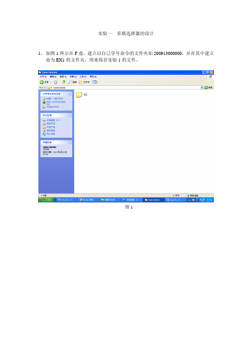
实验一多路选择器的设计1、如图1所示在F盘,建立以自己学号命令的文件夹如200913000000,并在其中建立命为EX1的文件夹,用来保存实验1的文件。
图12、如图2所示,点击Flie->New Project Wizard建立新的工程文件。
图23、将出现如图3所示的界面,点击如图所示的省略号,选择工程文件所要保存的位置。
图34、如图4所示,选中F:\20091300000\EX1并点击打开,进入如图5所示的界面图45、如图5所示,在工程文件保存的路径中显示刚才所选择的路径F:\20091300000\EX1图56、如图6所示,在What is the name of this project的栏目中输入工程的名字本实验临时取mux21a。
同时下面的顶层实体名也同步显示,然后点击Next进入到界面7。
图67、如图7所示,本界面是需要选择已有的文件,因为我们是新的工程,暂时没建立任何文件,所以直接点击Next进入到界面8。
图78、如图8所示,进行器件选择,我们要根据实验箱的芯片来进行器件选择。
选择CycloneII 系列。
图89、如图9所示,在CycloneII系列下选择EP2C5T144C8的芯片。
然后点击Next进行界面10。
图910、如图10所示,此界面是选择额外的综合、仿真工具软件,因为Quartus II本身自带有这些功能,所以我们不选择额外的工具软件。
直接点击Next进入到界面11。
图1011、如图11所示,此界面显示前面所有步骤的结果,包括文件保存路径、工程名、顶层实体名、芯片的系列与具体型号、额外的工具软件等等。
检查没错后点击Finish,如果有错点击Back返回进行修改。
图1112、如图12所示为已经建好工程的界面,显示工程名与工程文件路径。
图1213、如图13所示,点击新建文件按钮或File->New建立新文件,进入到如图14界面。
图1314、如图14所示,在Device Design Files栏选择VHDL File,然后点击OK进入下一界面。
Contractual Requirement : Obligation to submit programsMaster Construction Program [Contractual Tool] 3-months Rolling Program 3 個月滾動進度表 Weekly Program 每週進度表PROGRAMS 進度表Master Construction Program 主營造工作進度表 Utmost Importance Tools 最重要的工具Bases for all other planning 其他所有規劃的基礎 Project progress monitoring tool 項目進度監控的工具 Precedent on Contractor 's Rights: EOT / Progress Disruption Claims承包人權益的前提 : 合理延長完工期 / 進度受滋擾的索賠Master Construction Program (cont ' d 主營造工作進度表 (續)精準 : 只顯示主要的工作活動Detailed breakdown to be carried out in 3 months Rolling / Weekly Program分析在三個月滾動 / 每週進度表內才顯示Show Critical Path activities - bases for later EOT Analysis / Substantiation上的工作活動顯示出來-日後分析/支持合理延長完工期的基礎Indicates the needs time: 指出所需時間7.PROGRAMS 進度表o Common Contractor ' s Need Time: 常見的 承包人所需時間oConsents required dates (Foundation / Superstructure / External Fa?ade etc.) 申請開工紙所需時間o Design confirmation dates 設計送審所需時間 o Information required dates 索取資料所需時間oExample 例子8.METHOD STATEMENT & CONSTRUCTION SEQUENCE 施工方案及營造工作次序oPresentation of method to build & project sequencing 用途 : 1) 顯示施工方法及 2) 顯示施工次序oEssential for selecting appropriate plants & equipments for work對選擇合適的施工機械是重要的1. 2. 3.4.Projectplanning - Presentation Transcript次序PROJECT: PLANNING, SUBMISSION & PROCUREMENT PLANNING 規劃PROGRAMME PLANNING 進度規劃METHOD STATEMENT & CONSTRUCTION SEQUENCINGSITE LAYOUT PLAN & SITE FACILITIES PLANNING MANPOWER RESOURCES PLANNING人手資源規劃PROGRAMS 進度表 施工方案及營造工作工地佈局及工地設施規劃度表6.PROGRAMS 進度表合約要求 : 必須呈交進主營造工作進度表 [ 合約工具 ]5.Precise in nature : show only the major activities詳細的把折徑Examples ( 例子 ):Cyberport Method Statement 數碼港施工方案 Fu Tei Method Statement , 富泰施工方案 Animation - 1 , Animation - 2Construction sequencing: affect duration of plant deployment 營造工作次序 : 影響 僱用施工機械使用期的長短Graphic Presentation: ease of understanding by all parties 圖表 : 所有人都易於明 白SITE LAYOUT PLAN / SITE FACILITIES SCHEDULE 工地佈局 / 工地設施表Site Layout Plan 工地佈局圖Plant / Equipment Placement & Location 機械擺放及位置 Site Huts 工地房舍 Canteen 食堂 Storage Area 儲存區Temporary Haul Road 臨時運輸 Site Ingress / Egress points 工地出入口 Wheel Wash 清洗車輪 Water Treatment 水的處理Chemical Waste Storage Area 化學廢料儲存區 DG Store Area 危險品儲存區 Site Drainage 臨時渠SITE LAYOUT PLAN / SITE FACILITIES SCHEDULE 工地佈局圖 / 工地設施表 Site Layout Planning changes vs. Time 工地佈局計劃轉變與時間關係Site Layout Planning different from project to project 工地佈局計劃因應不同項目而 改變Disney - Site Infrastructure Project 迪斯奈 -工地基建項目 Fu Tei Site Layout Plan 富泰工地佈局圖 Cyberport Site Layout Plan 數碼港工地佈局圖 Examples 例子 :SITE LAYOUT PLAN / SITE FACILITIES SCHEDULE 工地佈局圖 / 工地設施表 Site Facilities Schedule 工地設施表 :List of plants / equipment over construction period 建造期內機械清單 Project budget control: Check against Tender Assumption & Budget項目成本控制查核招標階段的假設及成本預算Prompt arrangement of plant / equipment to the project 迅速為項目安排施工機械 Main Street Plant & Facility Schedule 迪斯奈 : 主街道機械設施表 Cyberport Plant Schedule 數碼港機械表 Example 例子 :MANPOWER RESOURCES PLAN 人力資源計劃 Project Organization 項目組織架構Project-in-charge (Project / Project Manager 項目經理 ) Site Manager (Site Agent) 工地經理Construction Team (Foremen 管工 / Supervisors)o o o o o o9.o o o o o o o o o o o o10.o o o o o o11.o o o o o o o12.o o o o oProject Coordination Team 項目協調員o Engineering 工程師/ Planning Team 規劃工程師o BS Engineering Team 機電工程師o Quantity Surveying Team 工料測量師o Site Surveying 測量員/ Setting Out Teamo Site Mechanics Team 機電技工o Site Material Control Team 材料管理員o Site Safety Team 工地安全人員o Other Supporting Team: Quality Control [ISO9001] / Environmental [ISO14001] 質量工程師/ 環保人員o Main Street Project Organization Chart 迪斯奈主街道項目組織架構表13. MANPOWER RESOURCES PLAN 人力資源計劃o Manpower Resources Planning / Schedule 人力資源表o Manpower In / Out at different period of the project 在不同階段人手調動情況o Project budget control: Check against Tender Assumption & Budget 項目預算監控查核投標階段的假設及成本預算o Main Street HR Budget 迪斯奈主街道人力資源預算o Main Street Manpower Monthly Review 迪斯奈主街道人力資源檢討o Main Street Planned vs. Actual Manpower Comparison 迪斯奈主街道: 計劃人手與實際人手比較o Example 例子:14. SUBMISSIONS 送審事項o CONTRACTUAL SUBMISSIONS 合約要求的送審事項o STATUTORY SUBMISSIONS 法例要求的送審事項15. CONTRACTUAL SUBMISSIONS 合約要求送審事項Submission required under Disney Contract: 迪斯奈合約要求送審事項w/in 15 days after Contract Commencement o Shop Drawings Submittal Schedule 制作圖送審時間表w/in 15 days after Contract CommencementSample 樣板/ Equipment Submittal Schedule機械送審事項Submissions Checklist 送審事項清單w/in 14 days after Contract Commencemento Contractor ' s Environmental Management Plan 承包人的環保計劃w/in 28 days after Contract Commencemento Contractor ' s Quality Plan 承包人的質量計畫w/in 28 days after Contract Commencemento Contractor ' s Safety Plan 承包人的安全計劃w/in 15 days after Contract Commencemento Procurement Schedule 採購時間表w/in 20 days after Contract Commencemento Works Program (Master Construction Program) 工作進度表w/in 14 days after Contract Awardo Bonds / Parent Company Guarantee 履約保函/ 母公司擔保16. STATUTORY SUBMISSIONS 法例要求送審事項Building Department (BD) 屋宇處:Environmental Department 環境保護處: [DSSP]o Detail Safety Supervision Plan 詳細安全監管計劃[BA10]o Notification of Appointing Building Contractor & Commencement of Work 委任建築承包商及開始工作通知[Form A]Application for Waste Water Discharge License申請排放污水準許證o Application for Waste Disposal Licenseo 申請掉棄廢物準許證[Form 1]o Application of Noise Permit 申請噪音紙[Form NA]o Notification pursuant to APC (Construction Dust) Reg 根據控制空氣污染條例而作出通知17. STATUTORY SUBMISSIONS 法例要求送審事項Labour Department 勞工處:o These are necessary submittals required under 這些送審事項的要求源自:o The Contract 合約o Statutory Ordinances 法例/ Regulations 法規o Therefore they must be promptly prepared & submit on time 因此必須準時地準備妥當及送審[Form 5]Notification of Employment of Safety Supervisor聘請安全督導員通知[Form 4]o Notification of Employment of Safety Officer聘請安全主任通知23.Enlist all the submissions (both contractual + mandatory) required 詳列所有送審事項(包括合約要求者及法定者)Imprint the submission required datesColumn to record actual submission dates. Fill-in onperiodically basis. 開設一欄以便記錄實際送審日期,定期把進度情況更新Acts as a self-checking list to avoid missing out submissions 清單用作自行檢查的基礎以防止在送審事宜上出現遺漏Examples 例子: Project Startup ChecklistSUBCONTRACTORS PR O CUREMENT18.19. [Form C]Notification of Construction Work 營造工作通知STATUTORY SUBMISSIONS 法例要求送審事項通常項目經理會把Usually, the Project Manager shallAssign the task to respective project team members 任務委派給項目小組內的有關成員Initial meeting with project team members for task assignmentSTATUTORY SUBMISSIONS 法例要求送審事項Establish a ‘Project Submission Checklist安排委派任務會議設訂一份項目送審事項清單20. PROCUREMENT 採購21.22.MATERIALS PROCUREMENTSUBCONTRACTORS PROCUREMENTContractual ArrangementNominated SubcontractorsNamed SubcontractorsDomestic Subcontractors材料採購招募分包商合約安排指定分包商提名分包商內部分包商SUBCONTRACTORS PROCUREMENT 招募分包商Nominated / Named Subcontractors 指定/提名分包商Scope of work / Subcontract package specified in the Contract內規定的分判計劃Nominated Subcontract: Client directly select theSubcontractor 業主直接選定分包商工作範圍/合約指定分包Instruct MC to enter subcontract with specific terms & conditions 指令總包與分包按指定的條款簽訂分判合約提名分包Named Subcontract: Client / MC joint ly selectedsubcontractors 業主/總包共同選定分包商Choice of subcontractors limitedApproval List in Contract只可在合約認可名單內公司挑選分包商MC enter subcontract with specific terms & conditions總包與分包簽訂按時特定條款擬定的分判合約駐明所需的送審日期項目啟始清單招募分包商o Freedom in subcont ractor 's selection is limited選定分包商的自由是有限的SUBCONTRACTORS PROCUREMENT 招募分包商24. SUBCONTRACTORS PROCUREMENT招募分包商 o Domestic Subcontractors內部分包商o Main Contractor total control on subcontract procurement總包對這類分包的招募工作有絕對控制權o Scope of work / Subcontract package decides by Main Contractor 工作範圍/分判計劃均由總包決定o Types 種類 :o Installation only subcontractors[Labour Only] 淨工分包商o Supply & Installation subcontractors [Labour + Materials] 包工料分包商oDesign / Supply / Installation Subcontractors包設計/工料分包商Carpentry & joinery work Plainting work油漆工程27.SUBCONTRACTORS PROCUREMENT 招募分包商o Design, Supply & Installation Subcontractors 設計,供應及安裝分包商oSpecialist work trace 專業工程 , example 例如 :25.SUBCONTRACTORS PROCUREMENT招募分包商 Installation Only Subcontractors (Cont' c 淨工分包商(續)小心:材料損耗 Precaution: Wastage control upon materials usage Main Contractor set wastage % allowance Bonus / Penalty Scheme總包設定可容許的損耗率賞/罰制度Sharing of gain if wastage is below the set target若損耗較目標低,省下來的大家分享Sets as incentive to Subcontractor in economic usage of material作為分包節省用料的獎勵計劃Example 例子 :Material wastage bonus clause in steel rebars fixing subcontract內的減低材料損耗條款在扎鐵分包合約26.SUBCONTRACTORS PROCUREMENT 招募分包商 包工料分包商Supply & Installation SubcontractorsMaterial acquisition is complex, better by specialist subcontractors雜的事務,交由專業分包商處理較好材料採購是複較好Wastage control better by subcontractors分包商對材料損耗控制Tensioning work預應力工程Aluminium windows 鋁窗 Kitchen equipmentTimber flooring work 廚具工程 木地板工程 Steel & metal work 鐵器工程 Interior fit-out work精裝修工程細木工買材料事宜Individual project work out 個別項目定出 Cement 水泥 Sand 沙 Rebars 鋼枝Approximately quantity of materials required 所需材料的數量Notify supplier through Purchase Departmento Subcontractor responsible for detailed design (structural & architectural) of the workbased upon Architect's ‘ Design Intent Drawings分包'商負責按照建築師的意念設計圖紙做詳細設計工作(結構及建築工程)o Curtain Walling System 玻璃幕牆系統oFabric Structure28.SUBCONTRACTORS PROCUREMENT招募分包商o Subcontracting Schedule 分判時間表 o Plan at outset of the project 項目啟始階段即行規劃o Decide the subcontract packages for the workso Listing of 列出 :o Dates setting depend on 日期的 厘定取決於 :o Scheduled tender out dates 發標日期oScheduled tender return dates 回標日期決定工程的分判計劃29.30.Schedule subcontract award dates定標日期o Programming of works 工程進度安排 oLead time shop drawings preparation準備制作圖所需時間Lead time material procurement / fabrication / delivery採購/制作/運送材料所需時間In-house processing time Examples 例子 :內部加工所需時間In-house tendering flow-chart 內部招標流程表 Subcontract Schedule 分判時間表MATERIAL PROCUREMENT材料採購 Common materials 常用材料Project specific materials項目指定材料MATERIALS PROCUREMENT 材料採購Common materials 常用材料 Materials common for all project Examples 例子 :適用各項目的材料Economic purchase if acquisition of materials in bulk經濟Collective purchase of materials by Purchase Department若大量購買材料將更由採購部集中辦理購31.Delivery time periodMATERIALS PROCUREMENTCommon materials (con 送貨期 材料採購't ) 常用材料(續)由採購部通知供應o Individual project issue Purchase Order (PO) when material is requiredo 當需要送貨時由個別項目發出採購指令32. MATERIAL PROCUREMENT 材料採購o Materials specific particularly / solely for the project 項目指定用料oApplication of material to other projects is limited在其他項目內使用該等材料的機會有限o Example 例子 : oMaterials Procurement Schedule for the project is required 項目需要材料採購時間表o Tiles 瓷磚o Ironmongery 小五金o Sanitary fittings & fixture 潔具 o Decorative works 裝飾33. MATERIAL PROCUREMENT 材料採購o Material Procurement Schedule 材料採購時間表 o Establish at outlet of the project 在項目啟始階段設定o Enlisting of 列出 : o Dates setting depend on 日期厘定有賴於 :o Material type & specification 材料種類及規範 o Manufacturer / Supplier 制造商/供應商 o Expected delivery date預計送貨日期oLatest date for material ordering (Sales Contract / PO placement訂購材料最後日期o Programming of works 工作進度的安排Lead time material fabrication / delivery 材料制造/運送所需時間Negotiation time required (e.g. overseas suppliers) 洽商合約所需時間oIn-house processing time間o 內部加工所需時34. o o o o 35. MATERIAL PROCUREMENT 材料採購Material Procurement Schedule (con ' t 材料採購時間表(續) Examples 例子 :In-house tendering flow-chart內部招標流程表Material procurement schedule 材料採購計劃END 完THE。
PT217583D Model Collaboration with AutoCAD Plant 3D and Revit Jason DrewAutodesk, Inc.Quentin ContrerasAutodesk, Inc.Learning Objectives∙Learn how to export and import models using AutoCAD Plant 3D∙Learn how to export and import models using Revit∙Learn how to update models with design changes∙Learn about model optimizationDescriptionDesign collaboration between architecture, engineering, and construction disciplines using AutoCAD software, industry-specific products and Revit software is possible with the proper workflows. This class outlines best practices for exporting and importing models between AutoCAD Plant 3D software and Revit software, managing design changes, and optimizing models. This session features Revit and AutoCAD Plant 3D.Your AU ExpertsJason DrewJason Drew is a Premium Support Specialist with Enterprise Priority Support at Autodesk. He has been with Autodesk since 2011 working with AutoCAD Plant 3D and P&ID since the initial releases of the software. His previous experience outside of Autodesk include Intergraph SmartPlant P&ID (admin and designer roles), software training and support for AutoCAD Plant and P&ID as an Application Engineer at D3 Technologies, and IT Support at several engineering companies in Tulsa, Oklahoma.Quentin ContrerasQuentin Contreras joined Autodesk in 2012 working with Frontline Customer Support and is currently a Premium Support Specialist working with Enterprise Priority Support focusing on customers with AutoCAD Plant Design software. Quentin has been involved with Autodesk technology for over 25 years (starting with release 10). He has worked with various companies as a CAD Manager and Designer with focus in the oil and gas industry and ammonia refrigeration. Prior to joining Autodesk, he primarily worked using AutoCAD P&ID to develop as-built drafting services for various industries. This required various levels of customization due to following set guidelines set up with each customer he worked with. He is also a contributor to the In the Pipes blog that provides helpful tips and tricks to AutoCAD Plant 3D and P&ID users.Table of ContentsIntroduction (3)AutoCAD Plant 3D to Revit (4)Exporting from Plant 3D (4)Manual Export (4)Batch Export (4)Importing into Revit (4)Method 1 – Link a CAD Model (4)Method 2 – Create and Insert a new part family (5)Model Management in Revit (8)Revit to AutoCAD Plant 3D (9)Exporting from Revit (9)Preparing 3D Views (9)Revit Export Settings (10)Importing into AutoCAD Plant 3D (11)Attach as XREF (11)Generating Orthographic Views in Plant 3D (11)Model Management and Optimization (12)Coordinate Systems, Positioning, and Alignment (12)Coordinate systems with AutoCAD Plant 3D (12)Shared Coordinates for Revit (12)Model Complexity (12)Plant 3D Model Optimization (12)Project Drawing Management (13)Revit Project Optimization for Plant 3D Performance (13)Conclusion (14)IntroductionIn the AEC industry, one software program cannot do it all. Separate applications are needed for structural, electrical, mechanical, architectural and civil infrastructure designs. The exchange of design data between the different programs is not seamless.One of the most critical workflows is between Revit and AutoCAD vertical products. This document provides best practices for collaboration with 3D models and how to maximize performance. The information provided builds on basic knowledge of AutoCAD Plant 3D and Revit.AutoCAD Plant 3D to RevitThis section explains how to export models from Plant 3D for use with Revit projects. In order for Revit to process and properly display the geometry for objects in the DWG file, the drawings must be exported as 3D solids. Revit does not utilize Object Enablers. The “Export to AutoCAD” function of Plant 3D Project Manager is a special function that will process all of the Plant objects (equipment, pipe, valves, fittings, etc.) and convert them to ACIS solids during the export process.Exporting from Plant 3DManual ExportThis option allows the export of a single project drawing by u sing the “Export to AutoCAD” comm and within Plant 3D Project Manager.Batch ExportIt is possible to export drawings in bulk or “batch” export with Plant 3D by using a custom .NET application.We have provided a sample with this class. This is an example of what is possible using custom programming and scripting to help automate the export process. The sample Batch Export for AutoCAD application is available for download from the Autodesk University class page. Importing into RevitThere are two methods outlined in this document for importing AutoCAD DWG files into Revit. The first method is very simple and automatically updates when the model changes, but does not give the best results in Revit. The second method requires more steps but allows AEC objects to be sectioned within views which then act more like other Revit objects. The choice then depends on a preference between ease of use and having complete visibility in Revit.Method 1 – Link a CAD ModelThe simplest way to use AutoCAD Plant 3D models in Revit is to link them directly into the Revit model.Note the following limitations with this method:∙Some of the AEC objects from the DWG willshow up as wireframe regardless of the detaillevel setting as there are no object enablersinside of Revit to handle this geometry∙Section and elevation views will not clip thegeometry properly∙This method is only recommended for 2Dlayouts such as plot plansMethod 2 – Create and Insert a new part familyThis method takes several steps, but gives better model visibility in Revit.There are two options with this method. The first is creating a new part family, importing the CAD model (DWG file) into the part family, and placing an instance into the Revit model. The drawback to this option is the part family must be edited each time a revision is made to the exported DWG file from Plant 3D; erasing the existing imported model and replacing it with the updated model.The second option uses an add-on for Revit (DWG Sync) to help automate the initial import of the CAD model into a new part family and updating it when revisions occur.First Option – Manual Part Family Creation and Update1. Launch AutoCAD Plant 3D2. Open the drawing with the model to be exported in Plant 3D and use the EXPORTTOAUTOCADcommand (or right-click on a drawing inside Project Manager and select Export to AutoCAD) to save a copy of the model with the Plant objects converted to AutoCAD 3D solids.3. Select a folder outside of the Plant 3D project to store the exported drawingsIf you want to include External References be sure to open the exported DWG files and use the XREF command to bind the references into a block.4. In Revit, create a new empty Revit Family. Use Generic Model.rft for the template.5. From the Insert ribbon click the Import CAD button to import the DWG:6. Click the Save button to save the part family7. Use the Load into Project and Close button on the Insert on the ribbon8. Click to select a location to place the new part familyIf desired, press the V key, then the G key to bring up the Visibility / Graphics Overrides window and turn on the site Project Base Point or Survey Point for placement and alignment of the part family in9. The Part Family can be placed again by locating it in Project Browser under the Generic Modelscategory and creating a new instance.Note, when updates occur, an edit will be required to the part family; erase the existing DWG geometry, import the updated DWG file, save, and reload the family into the project.Second Option - DWG Sync Add-in for RevitDWG Sync is an add-on for Revit that provides the following functions:∙Automatic creation of new Part Families for DWG files that have been exported from Plant 3D ∙Batch update of the existing Part Families containing the imported Plant 3D models (DWG files)Hyperlink to a web version of the diagram shown above:Autodesk Praxis Workflow Diagram - DWG Sync Add-in for RevitAs of November 10th, 2016, the DWG Sync for Revit add-in is available in the Autodesk Labs: It's Alive in the Labs: DWG Sync for Revit Tech PreviewPlease note, the labs project is scheduled to close on September 1st, 2017.Loading a new CAD model with DWG Sync – Import1. Open the main Revit model for the project2. Click the DWG Import button from the Add-Ins tab of the DWG Sync panel on the ribbon bar3. Browse to the location of the DWG file to be imported and click OK to continue4. The DWG import process will beginA new part family will be created using theGeneric Model template. Note, this could takesome time depending on the size andcomplexity of the Plant 3D model. After theimport process is complete you may receive awarning that some ACIS objects could not beimported. Click OK to close out this message.All of the geometry should be properlyprocessed if the drawing was properlyexported from Plant 3D.Note, DWG Sync will bring in any ExternalReferences that are attached to the original DWG file, regardless of the attachment type (overlay vs. attach.) If the exclusion of External References is desired, they must be unloaded inside the original DWG file before using DWG Import.5. Press the V key, then the G key to bring up the Visibility / Graphics Overrides window6. Scroll down to the list, expand the list for Site, and click the check-box for Project Base Point7. Move the base point of the imported CAD model (theAutoCAD 0,0 point) to the project base point as shown belowIf the model needs to be removed from the view and placedagain it can be accessed from the Families section of theProject Browser. Right-clicking on the name of the part familywill allow placement of a new instance by selecting CreateInstance.For more information, please refer the following articles:Project Base Points and Survey PointsTips for Working with Project Base Points and Survey PointsUpdating existing imported modelsAfter changes have occurred within the Plant 3D project drawings, another export (Export to AutoCAD) will be required. The recommendation is to overwrite the existing drawings. DWG Sync will detect this change and the models within the Revit part families can be refreshed / re-imported using the steps shown below.1. Click the DWG Sync button from the Add-Ins tab of the DWG Sync panel on the ribbon bar2. The DWG files that have changed will show a status of Refresh. The check-box for thesedrawings under the Import column will be automatically selected.3. Chen click the OK button4. The updated DWG will be imported, replacing the existing model inside the part familyModel Management in RevitWith the Plant models inserted as part families, they can be used in a Revit project for creating section and plan views.One recommended practice is to create a new Revit project model specifically for the imported Plant 3D DWG files. This allows the project to the linked into additional Revit projects and un-loaded and re-loaded as needed. This will also avoid importing additional categories andelements into the main models.Revit to AutoCAD Plant 3DIn order to use the 3D models from Revit within Plant 3D, it is necessary to export the models to a DWG file format. This section covers the configuration options and steps to use for proper export. Exporting from RevitPreparing 3D ViewsWhile it is possible to use the default 3D View within Revit to export the models to DWG files,this may not be the desired option. The default 3D View will contain all Revit objects, including interior doors, furniture, etc.Limiting Model Geometry Before ExportingBefore exporting a Revit model, limit model geometry to improve the performance of the export process.In Revit, a view of the building model contains many objects. When exporting a model for use in AutoCAD, Revit exports only the objects that are visible in the view (or views).If only a particular set of objects from Revit are needed for the export, customized 3D Views can be created specifically for exporting the DWG files. The visibility / graphic overrides and viewtemplates applied to the views will control what is exported out of Revit.Examples:∙Export all concrete slabs but exclude the rebar∙Export all structural steel beams and columns but exclude walls, ceilings, and floors∙Export the exterior of a building, but exclude all interior objects such as furniture By reducing the amount of model geometry (and its underlying data) that is exported, thefollowing is achieved:∙Improve performance of the export process∙Reduce the size of the exported file∙Improve performance of the importing application∙Reduce clutter (non-essential items) in the exported file, and hence the amount of work required to delete these objects from the file in the importing application∙Optimize the time it takes to generate orthographic views in Plant 3DUse the following techniques in Revit to reduce the amount of geometry to be exported:∙Turn off visibility of graphics∙Use a section box or a crop region∙Specify the detail level (Course, Medium, Fine)Revit Export SettingsExport as ACIS SolidsBefore the models are exported be sure to check the export options for Revit to ensure that solids are set to ACIS solids versus Polymesh. The orthographic drawing view generation for Plant 3D will not properly process Polymesh surfaces.Hyperlink to a web version of the diagram shown above:Autodesk Praxis Workflow Diagram - Revit Export to AutoCAD Plant 3DImporting into AutoCAD Plant 3DAttach as XREFIt is recommended to use “host” drawings or DWG files that will act as container drawings when importing the DWGs that have been exported out of Revit. This is accomplished by creating at new project drawing within Plant 3D Project Manager, opening the new drawing, then attaching the exported DWG from Revit. The main benefits of this practice:∙The exported DWGs from Revit do not need to be copied into the Plant 3D project. The host DWG belongs to the Plant project and contains the external reference (XREF) to thesedrawings which can be stored anywhere on the network.∙By avoiding the need to copy drawings into the Plant 3D project over and over (with each revision / export from Revit), the process of updating is simply opening the host DWG and allow it to reload the XREF.Generating Orthographic Views in Plant 3DIf the Revit models were exported to DWG format using ACIS solids, the orthographic view generation within Plant 3D should display all of the geometry properly in generated orthographic views. Note, the complexity of the exported Revit models will have an impact on the time it takes to generate orthographic views. Plant 3D uses the AutoCAD hidden line removal and it must process all of 3D solids in order to create orthographic views.Model Management and OptimizationCoordinate Systems, Positioning, and AlignmentKeeping models positioned and aligned with various coordinate systems is an important aspect to keep in mind to avoid any undesired movement during re-export and re-import.Coordinate systems with AutoCAD Plant 3DFor information about using state plane coordinates for positioning models within Plant 3D, please refer to this article on the Autodesk Knowledge Network:Using AutoCAD Plant 3D in a state plane coordinate project environmentShared Coordinates for RevitFor information about coordinate systems in Revit, please refer to thisAB1412: Navigating Through the Storm Using Coordinate Systems in RevitCI1599: Feeling Out of Sync? Get Your BIM Coordination On!Model ComplexityOptimizing the Plant 3D models in preparation for export to DWG files will help general performance with pan, zoom, and 3D orbit view operations within Revit. It will also help speed up the reloading of the models with each model revision.Plant 3D Model OptimizationWhen extremely complex models (such as those provided by vendors) are used for equipment, valves, in-line fittings, etc. the view performance of Revit can suffer when too many of thesemodels are imported. Using simplified models for these objects is recommended as a best practice.Figure 1. Detailed Vendor Equipment Model Figure 2. Parametric Plant 3D EquipmentProject Drawing ManagementOrganizing the Plant 3D project drawings into manageable process areas and units can helpstreamline the export process. Only the areas and units that have been updated will need to be exported after a model revision versus exporting the entire master model.For additional information, refer to the Managing large AutoCAD Plant 3D projects technical article on Autodesk Knowledge Network.Revit Project Optimization for Plant 3D PerformanceOptimizing the Revit models before exporting to DWG files as described in the article below will help with graphics performance with pan, zoom, and 3D orbit view operations within AutoCAD Plant 3D. It will also help speed up the orthographic view generation (hidden line removal) process.Autodesk® Revit 2017 Model Performance Technical NoteConclusionNow that you have an understanding of methods to share models from Plant 3D to Revit and Revit to Plant 3D, we hope these new workflows will expand your interoperability between engineering and design disciplines. If you have any questions, please feel free to reach out to us.Jason Drew***********************Quentin Contreras******************************。
使用Project编制进度计划1.三套时间的概念与运用1.1.基准时间项目进度计划排定后,经审核通过,即可成为指导整个项目施工过程的基准。
我们将这一计划中的时间明确记录下来,固定成为所谓的‘基准时间’。
这一时间将成为在后续工作中进行对比分析偏差的‘原点’。
在PROJECT软件中,工具栏里有跟踪项,然后点击保存比较基准,这里保存比较基准可以是整个项目,也可以是选中的一些节点。
选中某些节点进行保存非常适合进度一次不能够完全排好的情况,把已经确认的一些节点的比较基准保存下来,另外一些等计划时间安排好后再进行保存。
1.2.实际时间在施工的实际过程中,生产人员根据现场当前实际开工的分项工程,和完成的分项工程,在进度计划中填写‘实际时间’,这一组时间是现实的客观记录。
1.3.滚动计划时间这一计划在最初是和‘基准时间’完全相同的。
过程中,随着每一次填写分项工程实际开始时间或结束时间,我们需要马上重新排定进度计划。
比如,一个分项工作完成了,我们有了实际完成时间。
根据原先确定的各分项工程间的逻辑关系和计划耗用时间,我们可以重新排定全部计划。
为什么要重新排计划呢?因为,如果这项工作脱期了,有可能原先不是‘关键工作’的分项工程,在新的计划中成为了‘关键工作’。
也就是说我们的管理和控制重点将发生改变。
随着实际时间的填入,不断生成的计划,这就是滚动计划。
2.进度计划的操作步骤1)设置项目开始时间;2)设定工作时间;3)添加任务名称;4)设定任务级别;5)设定任务间的关系;6)设置任务工期;7)保存比较基准;2.1.设置项目开始时间;打开工具栏中的“项目信息”,如下图一;设置项目开始时间,如下图二;(图一:)(图二:)2.2.设定工作时间;Project默认的工作时间一般周六、周日为非工作时间。
而建筑工程中编制进度计划是不考虑周六、周日的。
所以要将Project中的默认工作时间进行更改,将周六、周日改为非默认工作时间。
操作步骤:工具->更改工作时间,选择要更改的时间列->将所选的-期设置为非默认工作时间,见下图一、图二;注:非工作时间在Project当中为灰色显示,工作时间为白色显示(图一:)(图二:)2.3.添加任务名称2.3.1.添加新任务;需要插入一个新的任务,如下图,需要在第8项任务前插入一项新任务,有两种方法1)点击任务8的任务序号,点击工具栏中的“插入”,如下图示:2)点击任务8的任务序号,点击鼠标右键“新任务”,如下图示:2.3.2.复制任务;1)首先选择需要复制的任务范围,如下图:2)在某任务前,粘贴复制的任务,或者在计划末粘贴复制的任务,点击鼠标右键进行粘贴,如下图:2.4.设定任务级别;在“任务名称”域中,单击需要降级(移动到层次结构中的低一级)或升级(移动到层次结构中的高一级)的任务。