MMP系列电机保护器样本
- 格式:pdf
- 大小:27.83 MB
- 文档页数:24
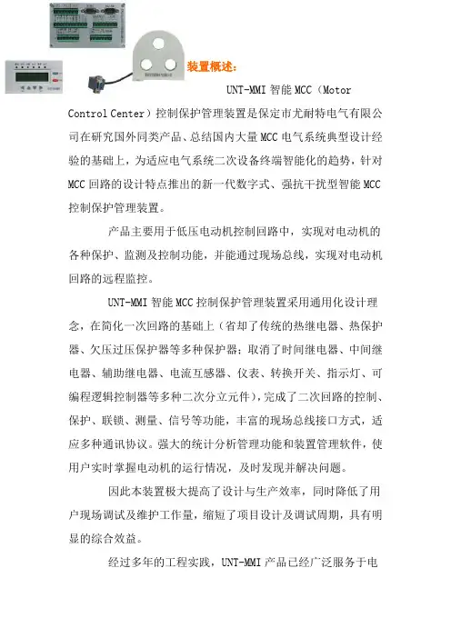
装置概述:UNT-MMI智能MCC(Motor Control Center)控制保护管理装置是保定市尤耐特电气有限公司在研究国外同类产品、总结国内大量MCC电气系统典型设计经验的基础上,为适应电气系统二次设备终端智能化的趋势,针对MCC回路的设计特点推出的新一代数字式、强抗干扰型智能MCC控制保护管理装置。
产品主要用于低压电动机控制回路中,实现对电动机的各种保护、监测及控制功能,并能通过现场总线,实现对电动机回路的远程监控。
UNT-MMI智能MCC控制保护管理装置采用通用化设计理念,在简化一次回路的基础上(省却了传统的热继电器、热保护器、欠压过压保护器等多种保护器;取消了时间继电器、中间继电器、辅助继电器、电流互感器、仪表、转换开关、指示灯、可编程逻辑控制器等多种二次分立元件),完成了二次回路的控制、保护、联锁、测量、信号等功能,丰富的现场总线接口方式,适应多种通讯协议。
强大的统计分析管理功能和装置管理软件,使用户实时掌握电动机的运行情况,及时发现并解决问题。
因此本装置极大提高了设计与生产效率,同时降低了用户现场调试及维护工作量,缩短了项目设计及调试周期,具有明显的综合效益。
经过多年的工程实践,UNT-MMI产品已经广泛服务于电力、化工、造纸、冶金、市政、煤炭、核工业等众多领域,运行稳定可靠。
装置特点:*采用32位工业级微处理器,速度快、精度高;*交流采样使用真有效值(RMS)算法,全面反映谐波电流的影响;*自适应变频采样技术,适用于变频器回路;*灵活的多种控制方式,各控制权限相互闭锁;*装置小型化设计,安装方式灵活;*全金属外壳设计,有效屏蔽外界电磁干扰;*汉字液晶,丰富的菜单显示,界面友好;*开关量输入回路采用强抗干扰设计,传输距离远,可靠性高;*装置内部控制触点带有保护电路,无需外加浪涌吸收器即可有效保护触点;*装置内带自记忆芯片,无需外配单独电源模块即可实现“抗晃电”功能及电压恢复自起动功能;*解决了热继电器和MCCB过载部分不能模拟MCC负荷的电特性和热特性的缺憾,在节省热继电器、简化MCCB构造的基础上,能更好地保护用电设备;*解决了MCCB瞬时脱扣器对长距离供电电动机端单相接地保护灵敏度不够的问题,省却了以往针对该问题单独加装单相接地保护的手段;*完善的过载保护。
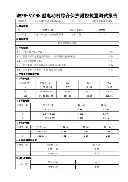
MMPR-810Hb型电动机综合保护测控装置调试报告
MMPR-810Hb型电动机综合保护测控装置调试报告
MMPR-810Hb型电动机综合保护测控装置调试报告
MMPR-810Hb型电动机综合保护测控装置调试报告
MMPR-810Hb型电动机综合保护测控装置调试报告
MMPR-810Hb型电动机综合保护测控装置调试报告
MMPR-810Hb型电动机综合保护测控装置调试报告
MMPR-810Hb型电动机综合保护测控装置调试报告
MMPR-810Hb型电动机综合保护测控装置调试报告
MMPR-810Hb型电动机综合保护测控装置调试报告
MMPR-810Hb型电动机综合保护测控装置调试报告
MMPR-810Hb型电动机综合保护测控装置调试报告
MMPR-810Hb型电动机综合保护测控装置调试报告
MMPR-810Hb型电动机综合保护测控装置调试报告
MMPR-810Hb型电动机综合保护测控装置调试报告
MMPR-810Hb型电动机综合保护测控装置调试报告
MMPR-810Hb型电动机综合保护测控装置调试报告。
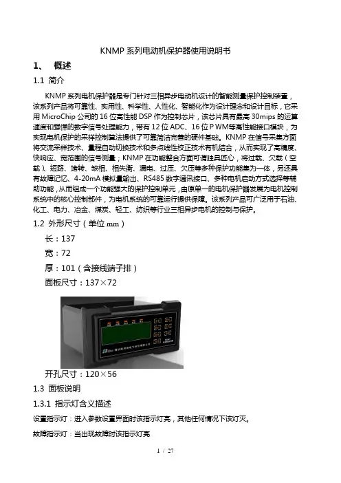
KNMP系列电动机保护器使用说明书1、概述1.1 简介KNMP系列电机保护器是专门针对三相异步电动机设计的智能测量保护控制装置,该系列产品将可靠性、实用性、科学性、人性化、智能化作为设计理念和设计目标,它采用MicroChip公司的16位高性能DSP作为控制芯片,该芯片具有最高30mips的运算速度和强悍的数字信号处理能力,带有12位ADC、16位PWM等高性能接口模块,为实现电机保护的采样控制算法提供了可靠简洁完善的硬件基础。
KNMP在信号采集方面将交流采样技术、量程自动切换技术和多点线性校正技术有机结合,从而实现了高精度、快响应、宽范围的信号测量;KNMP在功能整合方面可谓独具匠心,将过载、欠载(空载)、短路、堵转、缺相、相失衡、漏电、过压、欠压等多种保护功能集为一体,另还具有故障记忆、4-20mA模拟量输出、RS485数字通讯接口、多种电机启动方式选择等辅助功能,从而组成一个功能强大的保护控制单元,由原单一的电机保护器发展为电机控制系统中的核心控制部件,为电机系统的可靠运行提供保障。
该系列产品可广泛用于石油、化工、电力、冶金、煤炭、轻工、纺织等行业三相异步电机的控制与保护。
1.2 外形尺寸(单位mm)长:137宽:72厚:101(含接线端子排)面板尺寸:137×72开孔尺寸:120×561.3 面板说明1.3.1 指示灯含义描述设置指示灯:进入参数设置界面时该指示灯亮,其他任何情况下该灯灭。
故障指示灯:当出现故障时该指示灯亮脱扣指示灯:当脱扣继电器动作时该指示灯亮查询指示灯:当进入历史故障查询状态时该指示灯亮通讯指示灯:当保护器正常接收数据时,该灯闪烁;如果该灯一直亮表示接收到错误数据后一直没有接收到有效数据;如果该灯一直灭表示没有接收到任何数据。
1.3.2按键功能描述※设置键按设置键进入用户参数设置界面,再重复按该键可循环选择待设置的参数。
同时按设置键和移位键进入电流校准设置界面,再重复按设置键可循环选择待设置的参数。
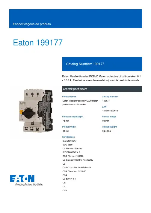
Eaton 199177Eaton Moeller® series PKZM0 Motor-protective circuit-breaker, 0.1 - 0.16 A, Feed-side screw terminals/output-side push-in terminalsGeneral specificationsEaton Moeller® series PKZM0 Motor-protective circuit-breaker199177401508197261675 mm 94 mm 45 mm 0.248 kgIEC/EN 60947 VDE 0660UL File No.: E36332 IEC/EN 60947-4-1 CSA File No.: 165628UL Category Control No.: NLRV ULCSA-C22.2 No. 60947-4-1-14 CSA Class No.: 3211-05 CSAUL 60947-4-1 CE UL CSAProduct NameCatalog Number EANProduct Length/Depth Product Height Product Width Product Weight CertificationsTurn buttonPhase-failure sensitivity (according to IEC/EN 60947-4-1, VDE 0660 Part 102)Phase failure sensitiveMotor protectionThree-pole 100,000 operations100,000 OperationsDIN rail (top hat rail) mounting optionalCan be snapped on to IEC/EN 60715 top-hat rail with 7.5 or15 mm height.40 Operations/hIII3Motor protective circuit breakerFinger and back-of-hand proof, Protection against direct contact when actuated from front (EN 50274)6000 V AC25 g, Mechanical, according to IEC/EN 60068-2-27, Half-sinusoidal shock 10 msAlso motors with efficiency class IE3Branch circuit: Manual type E if used with terminal, or suitable for group installations, (UL/CSA)-25 - 55 °C, Operating range≤ 0.25 %/K, residual error for T > 40°-5 - 40 °C to IEC/EN 60947, VDE 0660Actuator type Features Functions Number of poles Lifespan, electricalLifespan, mechanicalMounting MethodMounting positionOperating frequencyOvervoltage categoryPollution degreeProduct categoryProtectionRated impulse withstand voltage (Uimp) Shock resistanceSuitable forTemperature compensationAltitude Terminal capacity (flexible with ferrule)Max. 2000 m-25 °C55 °C-25 °C40 °C-40 °C80 °CDamp heat, constant, to IEC 60068-2-78 Damp heat, cyclic, to IEC 60068-2-301 x (1 - 6) mm², Screw terminals2 x (1 - 6) mm², Screw terminals1 x (0.5 - 2.5) mm², Push-in terminals, ferrule to DIN 46228-12 x (0.5 - 2.5) mm², Push-in terminals, ferrule to DIN 46228-11 x (0.5 - 1.5) mm², Push-in terminals, ferrule to DIN 46228-42 x (0.5 - 1.5) mm², Push-in terminals, ferrule to DIN 46228-41 x (0.5 - 2.5) mm², Push-in terminals2 x (0.5 - 2.5) mm², Push-in terminals1 x (0.5 - 2.5) mm², Push-in terminals2 x (0.5 - 2.5) mm², Push-in terminals18 - 10, screw terminals20 - 14, Push-in terminals10 mm1.7 Nm, Screw terminals, Main cable50 Hz 60 Hz 0.16 A 0 kW 0 kW 690 V 690 V 0.16 A 50 kA, 600 Y/347 V, SCCR (UL/CSA) 65 kA, 240 V, SCCR (UL/CSA)65 kA, 480 Y/277 V, SCCR (UL/CSA)Basic device fixed 15.5 x Iu, Trip Blocks ± 20% tolerance, Trip blocks2.5 A, Irm, Setting range max.5 HPPush-in terminals on output side Screw terminals on feed sideAmbient operating temperature - min Ambient operating temperature - maxAmbient operating temperature (enclosed) - min Ambient operating temperature (enclosed) - max Ambient storage temperature - minAmbient storage temperature - maxClimatic proofing Terminal capacity (flexible)Terminal capacity (solid)Terminal capacity (solid/stranded AWG) Stripping length (main cable) Tightening torqueRated frequency - minRated frequency - maxRated operational current (Ie)Rated operational power at AC-3, 220/230 V, 50 Hz Rated operational power at AC-3, 380/400 V, 50 Hz Rated operational voltage (Ue) - minRated operational voltage (Ue) - maxRated uninterrupted current (Iu)Short-circuit current rating (type E)Short-circuit releaseAssigned motor power at 230/240 V, 60 Hz, 1-phase Connection0 0 00.16 A0.16 AOverload trigger: tripping class 10 A5.39 W0 W0 W0 WMeets the product standard's requirements.Meets the product standard's requirements.Meets the product standard's requirements.Meets the product standard's requirements.Meets the product standard's requirements.Does not apply, since the entire switchgear needs to be evaluated.Does not apply, since the entire switchgear needs to be evaluated.Meets the product standard's requirements.DA-DC-00004888.pdfDA-DC-00004918.pdfeaton-manual-motor-starters-pkzm-pkzm0-dimensions-002.eps 121X042121X002eaton-manual-motor-starters-pkz-dimensions.epseaton-manual-motor-starters-pkz-dimensions-002.epsETN.PKZM0-0,16-SPI16.edzIL03407011Zpkzm0_s16_pi.dwgpkzm0_s16_pi.stpNumber of auxiliary contacts (change-over contacts) Number of auxiliary contacts (normally closed contacts) Number of auxiliary contacts (normally open contacts)Overload release current setting - min Overload release current setting - max Tripping characteristicEquipment heat dissipation, current-dependent PvidHeat dissipation capacity PdissHeat dissipation per pole, current-dependent PvidStatic heat dissipation, non-current-dependent Pvs10.2.2 Corrosion resistance10.2.3.1 Verification of thermal stability of enclosures10.2.3.2 Verification of resistance of insulating materials to normal heat10.2.3.3 Resist. of insul. mat. to abnormal heat/fire by internal elect. effects10.2.4 Resistance to ultra-violet (UV) radiation10.2.5 Lifting10.2.6 Mechanical impact10.2.7 Inscriptions Declarations of conformity DesenhoseCAD modelInstruções de instalação mCAD model10.3 Degree of protection of assembliesDoes not apply, since the entire switchgear needs to be evaluated.10.4 Clearances and creepage distancesMeets the product standard's requirements.10.5 Protection against electric shockDoes not apply, since the entire switchgear needs to be evaluated.10.6 Incorporation of switching devices and componentsDoes not apply, since the entire switchgear needs to be evaluated.10.7 Internal electrical circuits and connectionsIs the panel builder's responsibility.10.8 Connections for external conductorsIs the panel builder's responsibility.10.9.2 Power-frequency electric strengthIs the panel builder's responsibility.10.9.3 Impulse withstand voltageIs the panel builder's responsibility.10.9.4 Testing of enclosures made of insulating materialIs the panel builder's responsibility.10.10 Temperature riseThe panel builder is responsible for the temperature rise calculation. Eaton will provide heat dissipation data for the devices.10.11 Short-circuit ratingIs the panel builder's responsibility. The specifications for the switchgear must be observed.10.12 Electromagnetic compatibilityIs the panel builder's responsibility. The specifications for the switchgear must be observed.10.13 Mechanical functionThe device meets the requirements, provided the information in the instruction leaflet (IL) is observed.Eaton Corporation plc Eaton House30 Pembroke Road Dublin 4, Ireland © 2023 Eaton. Todos os direitos reservados. Eaton is a registered trademark.All other trademarks areproperty of their respectiveowners./socialmedia。
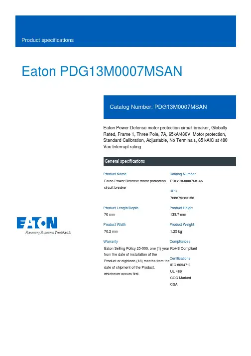
Eaton PDG13M0007MSANEaton Power Defense motor protection circuit breaker, Globally Rated, Frame 1, Three Pole, 7A, 65kA/480V, Motor protection, Standard Calibration, Adjustable, No Terminals, 65 kAIC at 480 Vac Interrupt ratingEaton Power Defense motor protection circuit breakerPDG13M0007MSAN 78667928315876 mm 139.7 mm 76.2 mm 1.25 kg Eaton Selling Policy 25-000, one (1) year from the date of installation of theProduct or eighteen (18) months from thedate of shipment of the Product,whichever occurs first.RoHS Compliant IEC 60947-2UL 489CCC MarkedCSAProduct NameCatalog NumberUPCProduct Length/Depth Product Height Product Width Product Weight WarrantyCompliancesCertifications7 A1Three-pole PD1 Global Class A600 VacThermomagnetic No Terminals65 kAIC at 480 Vac25 kAIC at 600 V (UL/CSA)35 kAIC Icu at 125 Vdc100 kAIC Icu/100 kAIC Ics/220 kAIC Icm at 240 V (IEC) 70 kAIC Icu/50 kAIC Ics/154 kAIC Icm at 380-415 V (IEC) 65 kAIC at 480 V (UL)100 kAIC at 240 V (UL)35 kAIC Icu at 250 Vdc Eaton Power Defense MCCB PDG13M0007MSAN 3D drawing Consulting application guide - molded case circuit breakersPower Defense technical selling bookletPower Defense molded case circuit breaker selection poster Power Defense brochurePower Defense molded case circuit breakers - Frame 1 product aid Molded case circuit breakers catalogEU Declaration of Conformity - Power Defense molded case circuit breakersPDG1 CCC certificationPDG1 CSA certificationPDG1 UL authorizationPower Defense Declaration concerning California’s Proposition 65Amperage Rating FrameNumber of poles Circuit breaker type ClassVoltage ratingSwitch off technique TerminalsInterrupt rating Interrupt rating range 3D CAD drawing package Application notes BrochuresCatalogsCertification reports Installation instructionsPower Defense Frame 1 UL global DIN rail adapter metal three pole -IL012187ENPower Defense Frame 1 UL global Padlockable Handle Lock Hasp -IL012225ENPower Defense Frame 1 UL global lock padlockable handle haspIL012180ENPower Defense Frame 1 UL Global variable depth rotary handle mech installation instructions - IL012308ENPower Defense Frame 1 UL global tunnel terminal (aluminum) 125A 3P - IL012166EN H03Power Defense Frame 1 UL global screw terminal end cap kit 125A 3P - IL012163ENPower Defense padlockable handle lock hasp top off only installation instructions - IL012226ENPower Defense Frame 1 UL global terminal shield cover IP30 3P -IL012174ENPower Defense Frame 1-2-3-4 IP door barrier assembly instructions -IL012278ENPower Defense Frame 1 UL global box terminal (steel) 125A 3P -IL012165EN H03Power Defense Frame 1 UL global DIN rail adapter 2, 3, 4-pole -IL012185ENPower Defense Frame 1 UL global handle block non padlockable -IL012177ENPower Defense Frame 1 UL global screw terminal end cap kit metric 125A 3P - IL012171ENPower Defense Frame 1 UL global DIN rail adapter three or four pole - IL012186ENPower Defense Frame 1 UL global interphase barrier - IL012176EN Power Defense Frame 1 UL global handle block padlockable off only - IL012179ENPower Defense Frame 1 Instructions - IL012152ENPower Defense Frame 1 UL global handle block padlockable -IL012178ENPower Defense Frame 1 UL global interphase barrier instructions -IL012313ENInstallation videosPower Defense Frame 1 UL Global Aux, Alarm, ST and UVR Animated Instructions.rhMultimediaPower Defense Frame 3 Variable Depth Rotary Handle Mechanism Installation How-To VideoEaton Power Defense for superior arc flash safetyEaton Corporation plc Eaton House30 Pembroke Road Dublin 4, Ireland © 2023 Eaton. All Rights Reserved. Eaton is a registered trademark.All other trademarks areproperty of their respectiveowners./socialmediaPower Defense Frame 5 Trip Unit How-To VideoPower Defense Frame 1 Aux, Alarm, and Shunt Trip How-To Video Power Defense BreakersPower Defense Frame 2 Variable Depth Rotary Handle Mechanism Installation How-To VideoPower Defense molded case circuit breakers Power Defense Frame 6 Trip Unit How-To Video Eaton Specification Sheet - PDG13M0007MSAN Power Defense time current curve Frame 1 - PDG1Power Defense time current curves MCP Motor Circuit Protection – PD1, PD2, PD3Single and double break MCCB performance revisited Safer by design: arc energy reduction techniques Molded case and low-voltage breaker healthSpecifications and datasheetsTime/current curvesWhite papers。

珠海万力达电气股份有限公司MMPR-31C电动机保护测控装置技术使用说明书编制:校核:姜万东审批:林存利文件编号:WLD[K]-JY-262-2011 版本号:V1.01.01出版日期:2011 年 11 月版权所有:珠海万力达电气股份有限公司注:我公司保留对此说明书修改的权利。
如果产品与说明书有不符之处,请您及时与我公司联系,我们将为您提供相应的服务。
技术支持电话:************传真:************前言1.型号说明MMPR-31C系列保护结构型式为C型,MMPR-31C可支持三相电流保护,也可支持两相电流保护。
定货时,请声明。
2.引用标准《静态继电保护及安全自动装置通用技术条件》 DL 478-2001《继电保护和安全自动装置技术规程》 GB/T 14285-2006《电力装置的继电器保护和自动装置设计规范》 GB50062-92《继电保护和安全自动装置基本实验方法》 GB/T 7261-20083.使用注意事项✓本系列保护所涉及负序电压均以相电压合成得到,所有复合电压闭锁过流中低电压元件取线电压,三个线电压中有一个小于低电压定值,低电压元件动作,开放过电流保护。
✓当CT接线方式选择为两相时,测量B相电流由测量A相、测量C相计算得到。
✓本系列装置中涉及4种标准曲线的反时限保护,如果故障电流超过额定电流的20倍时,反时限元件将按照20倍时的动作时间出口。
✓装置通电前,必须进行外观检查,保证面板完好无划痕、紧固螺钉无松动、装置可靠接地、各插件紧固螺丝拧紧以及端子接触良好。
✓装置加上电源后,面板上“运行”指示灯应该闪烁、液晶循环显示保护、测量等运行数据。
✓装置内部的操作回路只适用于直流电源,若为交流电源,须经整流滤波后接入。
✓禁止带电插拔各插件板,否则损坏装置。
✓禁止装置在带一次设备运行中,进行开出实验。
目录1产品说明 (1)1.1适用范围 (1)1.2功能及特点 (1)1.2.1 保护功能 (1)1.2.2 辅助功能 (1)1.2.3 测控功能 (1)1.2.4 通讯功能 (1)1.2.5 装置特点 (2)1.2.6 主要技术参数 (2)1.2.7 硬件结构 (3)2原理说明 (4)2.1启动时间过长保护 (4)2.2两段式定时限过流保护 (4)2.3两段负序过流保护 (4)2.4零序过流保护 (5)2.5过负荷保护 (5)2.6过热保护 (6)2.7电压保护 (6)2.7.1低电压保护 (6)2.7.2 过电压保护 (7)2.8PT断线监视 (7)2.9工艺联锁保护 (7)2.10CT断线 (7)2.11低频减载 (7)2.12同步电动机保护 (8)2.13启动电流有效值记录 (9)2.14故障录波 (9)3装置参数及定值设置说明 (10)3.1系统参数 (10)3.2定值清单 (11)4模拟量及开入开出说明 (14)4.1模拟量的监测 (14)4.2开入量检验 (15)4.3开出量检验 (16)5操作说明 (17)5.1装置面板示意图 (17)5.2键盘使用及液晶显示说明 (17)附录1:装置端子图 (24)附录2:装置典型接线图 (25)附录3: MXPR-31C系列装置的操作回路 (26)1产品说明1.1 适用范围MMPR-31C微机电动机保护适用于3kV~10kV 电压等级的中高压电动机保护测控,可用于各种容量的大中型电动机的综合保护,也可用于超大型电动机主保护和后备保护的双重配置。
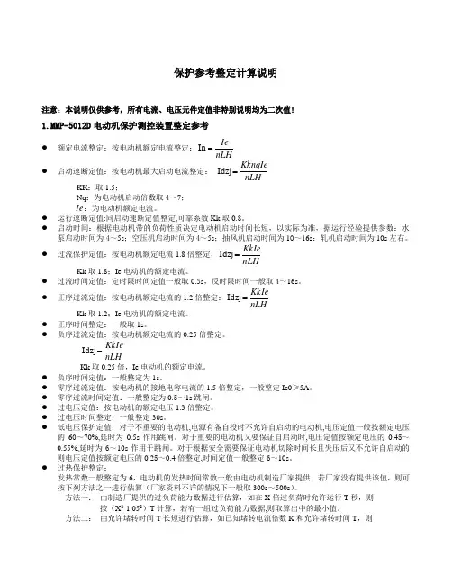
保护参考整定计算说明注意:本说明仅供参考,所有电流、电压元件定值非特别说明均为二次值!1.MMP-5012D 电动机保护测控装置整定参考● 额定电流整定:按电动机额定电流整定:nLHIe =In ● 启动速断定值:按电动机最大启动电流整定: nLH KknqIe =Idzj KK :取1.5;Nq :为电动机启动倍数取4~7;Ie :为电动机额定电流。
● 运行速断定值:同启动速断定值整定,可靠系数Kk 取0.8。
● 启动时间:根据电动机带的负荷性质决定电动机启动时间长短,以实际为准,据运行经验提供参数:水泵启动时间为4~5s ;空压机启动时间为4~5s ;抽风机启动时间为10~16s :轧机启动时间为10s 左右。
● 过流保护定值:按电动机额定电流1.8倍整定,nLHKkIe =Idzj Kk 取1.8;Ie 电动机的额定电流。
● 过流时间定值:定时限时间定值一般取0.5s ,反时限时间一般取4~16s 。
● 正序过流定值:按电动机额定电流的1.2倍整定:nLH KkIe =Idzj Kk 取1.2;Ie 电动机的额定电流。
● 正序时间整定:一般取1s 。
● 负序过流定值:按电动机额定电流的0.25倍整定。
nLHKkIe =Idzj Kk 取0.25倍,Ie 电动机的额定电流。
●负序时间定值:一般整定为1s 。
●零序过流定值:按电动机的接地电容电流的1.5倍整定,一般整定Ic0≥5A 。
●零序过流时间定值:一般整定为0.5~1s 跳闸。
●过电压定值:按电动机的额定电压1.3倍整定。
●过电压时间整定:一般整定30s 。
● 低电压保护定值:对于不重要的电动机,电源有备自投时不允许自启动的电动机,电压定值一般按额定电压的60~70%,延时为0.5s 作用跳闸。
对于重要的电动机又要保证自启动时,电压定值按额定电压的0.45~0.55%,延时为6~10s 作用于跳闸。
对于根据安全需要保证电动机切除时间长且失压后又不允许自启动的则电压定值按额定电压的0.25~0.4倍整定,时间定值一般整定6~10s 。
电动机保护器阐明书1.概述微机监控电机保护器合用于AC380V、AC660V低压系统,作为低压异步电动机和增安型电动机保护、监测和控制新一代智能化综合装置。
除了先进电动机保护、监控功能,还提供了设备运营和跳闸记录以及额定参数等重要信息,并且采用现场总线方式构造,为当代化设备管理带来很大便利;广泛用于石油、化工、电力、冶金、煤炭、轻工、纺织等行业。
符合原则:GB3836.3-、GB14048.4-、IEC2552.特点●“tE时间保护”符合关于增安型防爆电动机过载保护国标(GB3836.3-)●交流采样,测量A、B、C三相电流及控制回路电压●现场显示电动机运营状态,保存三次电动机故障跳闸记录●一路保护输出,一路自定义继电器输出,一路4~20mA电流输出或RS485接口●高清晰度宽温液晶显示,并具备背景光,跟随电动机运营状态和顾客规定实时显示●三相电流不平衡、断相、过压、欠压、自启动等功能顾客可取可舍●采用E2PROM存储技术,实现参数电设定,掉电后设定参数仍保存下来,勿须再设定●采用RS485通信总线,可广泛用于各种监控系统作为带有电机保护及控制智能化监控单元●一机多用,可取代电流表、电压表、热继电器、电流互感器、时间继电器和漏电继电器等3.重要功能保护功能:过流、堵转、断相、三相电流不平衡、过压、欠压、短路、漏电(选配)等故障保护测量功能:三相电流、控制回路电压测量和显示通用功能:增安型电动机保护、三相异步电动机保护、馈线保护,三种保护装置通用通信功能:通过本保护器RS485接口与上层系统通信。
总线接口支持参数设立、控制及监测等功能,支持Modbus通信合同。
普通采用RS485总线接口进行物理连接,普通上位机或PLC设备作为主站,本保护器作为子站。
电流输出:4~20mA电流输出,20mA相应电流值可设。
4.型号阐明微机电动机保护监控装置合用于AC660V及如下低压系统,作为低压电动机馈线终端保护、监测和控制新一代智能化综合装置。

珠海万力达电气股份有限公司http://zhwldMMPR-310Hb-3X型微机电动机保护装置用户手册文件编号:WLD[K]-JY-01-402-2019 2019年6月前言1.版本说明1.1硬件版本:V1.01.2软件版本:V1.01.3通讯发码表:《300系列保护装置通讯发码表》(WLD[K]-JF-01-301-2019)2.型号说明MMPR-310Hb-3X型电动机保护具有A、B、C三相电流输入;MMPR-310Hb-2X型电动机保护具有A、C两相电流输入。
3.引用标准《静态继电保护及安全自动装置通用技术条件》 DL 478-20191.产品说明MMPR-310Hb-3X型微机电动机保护装置主要用于大中容量电动机的综合保护和测控。
该装置的特点:采用高档16位单片机作控制器,计算速度快,保护功能齐全,动作可靠。
具有掉电记忆芯片存储保护定值;具有掉电实时时钟;可准确记录8次保护动作信息;具有完善的自检功能。
采用汉化液晶显示,通过键盘对各项菜单进行操作,操作简便,显示直观。
该装置带有高速的CAN、RS485通讯接口,所有保护动作信息可通过CAN网或RS485通讯网上传到后台计算机监控系统。
装置完成保护功能的同时把远动三遥功能集成于机箱内,保护、测量电流分别从不同CT引入,所有的保护动作信息、遥信、遥测、遥控均可通过通讯网实现。
装置内配有完善的操作箱功能,可直接对断路器进行操作。
该装置为插件结构,体积小,接线简单,防震、防电磁干扰能力强,可组屏或直接安装于开关柜,是变电站自动化系统的理想设备。
2.功能描述2.1正序保护保护电流中任何一相电流的幅值大于正序电流定值并达到正序延时时,保护动作。
电动机启动时间内与启动时间后的正序电流定值可分别整定。
2.2负序保护负序保护可对电动机断相、反相及严重不平衡运行的情况进行有效的保护。
负序定时限保护是当负序电流超过负序定时限电流定值并达到整定延时时保护动作。