FEM9.311 Rules for the Design of Storage and Retrieval Machines Structures S欧洲物料搬运协会.
- 格式:pdf
- 大小:473.00 KB
- 文档页数:6

A blood case caused by a watchToday I want to tell you a story.The hero of the story is li lei.One morning li lei woke up and washed, he put his watch on the edge of the washstand, his wife (do you know who his wife is?).Han Meimei was afraid the watch would get wet, so she took the watch and put it on the table.At this moment, their son came to the table and wanted to take the bread, but knocked his father's watch on the ground and broke it.li lei loved the watch, so he beat his son and scolded his wife. Han Meimei was also angry, and the two started to quarrel. Then li lei didn't eat the breakfast and drove directly to the company. When he arrived at the company, li lei suddenly remembered that he had left his bag at home, so he had to turn around and go home.But no one was at home. Han meimei went to work and the son went to school. Li lei's own key was in the bag, so he couldn't get into the door and had to call han meimei for the key.When han meimei rushed home, she knocked over a fruit stand and the owner did not let her go.She had to pay the money for the owner.When li lei arrived at the company, he was 15 minutes late, so he was scolded by his boss. Li lei was in a terrible mood. Han meimei was also deducted for early retirement.Their son, who played baseball for the day, could have done well, but was out of the mood.What a terrible day!Isn't it?At that time, a mysterious man appeared in front of li lei, said to him: "hello, li lei, I am festinger, this story's author, if I can let time back to this morning, your watch broke at the moment, would you like?"Of course he would!So, let's see what happens next.The watch was broken.Li lei love his watch, but also know that it can't change the fact and to comfort his son: "it doesn't matter, I can take to be repaired watches, but the next time you may not be so careless."After that, the family had a happy breakfast and went to work on their own.As we all expected, the son was happy, the wife was happy, li lei was also happy, then everything would not happen.This is the festinger rule.He stresses that 10 percent of our lives are beyond our control, and 90 percent of what we can control.In this case, the watch is 10 percent off our control.The next series of things is another 90 percent.Although we can't control the previous 10 percent, we can fully determine the remaining 90 percent through our mindsets and actions.In real life, I often hear people complain: how can I be so unlucky? There is always something bad about me every day. Who can help me?Only we can help ourselves.If you know and can use the "festinger rule", all problems will be solved。

EUROPEAN STANDARDNORME EUROPÉENNEEUROPÄISCHE NORMEN ISO 8589 February 2010ICS 67.240 English VersionSensory analysis - General guidance for the design of testrooms (ISO 8589:2007)Analyse sensorielle - Directives générales pour laconception de locaux destinés à l'analyse (ISO 8589:2007) Sensorische Analyse - Allgemeiner Leitfaden für die Gestaltung von Prüfräumen (ISO 8589:2007) This European Standard was approved by CEN on 31 January 2010.CEN members are bound to comply with the CEN/CENELEC Internal Regulations which stipulate the conditions for giving this European Standard the status of a national standard without any alteration. Up-to-date lists and bibliographical references concerning such national standards may be obtained on application to the CEN Management Centre or to any CEN member.This European Standard exists in three official versions (English, French, German). A version in any other language made by translation under the responsibility of a CEN member into its own language and notified to the CEN Management Centre has the same status as the official versions.CEN members are the national standards bodies of Austria, Belgium, Bulgaria, Croatia, Cyprus, Czech Republic, Denmark, Estonia, Finland, France, Germany, Greece, Hungary, Iceland, Ireland, Italy, Latvia, Lithuania, Luxembourg, Malta, Netherlands, Norway, Poland, Portugal, Romania, Slovakia, Slovenia, Spain, Sweden, Switzerland and United Kingdom.EUROPEAN COMMITTEE FOR STANDARDIZATION C O M I T É E U R O P ÉE N D E N O R M A LI S A T I O NEUR OP ÄIS C HES KOM ITEE FÜR NOR M UNGManagement Centre: Avenue Marnix 17, B-1000 Brussels© 2010 CEN All rights of exploitation in any form and by any means reservedworldwide for CEN national Members.Ref. No. EN ISO 8589:2010: EForewordThe text of ISO 8589:2007 has been prepared by Technical Committee ISO/TC 34 “Food products” of the International Organization for Standardization (ISO) and has been taken over as EN ISO 8589:2010.This European Standard shall be given the status of a national standard, either by publication of an identical text or by endorsement, at the latest by August 2010, and conflicting national standards shall be withdrawn at the latest by August 2010.Attention is drawn to the possibility that some of the elements of this document may be the subject of patent rights. CEN [and/or CENELEC] shall not be held responsible for identifying any or all such patent rights.According to the CEN/CENELEC Internal Regulations, the national standards organizations of the following countries are bound to implement this European Standard: Austria, Belgium, Bulgaria, Croatia, Cyprus, Czech Republic, Denmark, Estonia, Finland, France, Germany, Greece, Hungary, Iceland, Ireland, Italy, Latvia, Lithuania, Luxembourg, Malta, Netherlands, Norway, Poland, Portugal, Romania, Slovakia, Slovenia, Spain, Sweden, Switzerland and the United Kingdom.Endorsement noticeThe text of ISO 8589:2007 has been approved by CEN as a EN ISO 8589:2010 without any modification.BS EN ISO 8589:2010EN ISO 8589:2010 (E)© ISO 2010 iiiContentsPage 1Scope.....................................................................................................................................................1 2Normative references...........................................................................................................................1 3Terms and definitions...........................................................................................................................1 4Principle.................................................................................................................................................1 5Creation of test rooms..........................................................................................................................2 6Testing area...........................................................................................................................................2 6.1General requirements...........................................................................................................................2 6.2Testing booths......................................................................................................................................4 6.3Area for group work..............................................................................................................................5 7Preparation area....................................................................................................................................6 7.1General requirements...........................................................................................................................6 7.2Equipment .............................................................................................................................................6 8Office......................................................................................................................................................7 8.1General requirements...........................................................................................................................7 8.2Size.........................................................................................................................................................7 8.3Fittings...................................................................................................................................................7 9Additional areas....................................................................................................................................7 10 Additional information.. (7)Annex A (informative) Examples of test room layouts (8)Bibliography (16)BS EN ISO 8589:2010EN ISO 8589:2010 (E)This page deliberately set blankINTERNATIONAL STANDARD1Sensory analysis — General guidance for the design of test rooms1 ScopeThis International Standard provides general guidance for the design of test rooms intended for the sensory analysis of products.It describes the requirements to set up a test room comprising a testing area, a preparation area, and an office, specifying those that are essential or those that are merely desirable.This International Standard is not specific for any product or test type.NOTE The test space can be similar for food and non-food products that are evaluated using sensory methods. However, the test rooms might need to be adapted for each specialized use. Modifications to the design are often needed for specific products and for specific types of testing. This is particularly true if the test rooms are to be used for the evaluation of non-food products.Although many of the general principles are similar, this International Standard does not address test facilities for the specialized examination of products in inspection or in-plant quality-control applications.2 Normative referencesThe following referenced documents are indispensable for the application of this document. For dated references, only the edition cited applies. For undated references, the latest edition of the referenced document (including any amendments) applies.ISO 5492, Sensory analysis — Vocabulary3 Terms and definitionsFor the purposes of this document, the terms and definitions given in ISO 5492 apply.4 PrincipleThe test rooms are designed⎯ to conduct sensory evaluations under known and controlled conditions with a minimum of distractions,and⎯ to reduce the effects that psychological factors and physical conditions can have on human judgement. EN ISO 8589:2010 (E)BS EN ISO 8589:2010© BSI 201025 Creation of test roomsThe creation of test rooms intended for sensory analysis differs, depending on whether a new building or an existing facility is used.A typical test facility comprises the following:⎯ a testing area in which work may be carried out individually in testing booths or in groups;⎯ a preparation area;⎯ an office;⎯ a cloakroom and toilets;⎯ a storage room for supplies;⎯ a storage room for samples;⎯ a waiting room for assessors.The minimum requirements are⎯ a testing area in which work may be carried out individually in testing booths or in groups, and⎯ a preparation area.The test room should be easily accessible to the assessors and should not be located in an area where there is a heavy traffic flow (for example, near a cafeteria), unless arrangements have been made to reduce noise and distraction. Reasonable arrangements should also be made for accessibility to the area by those with physical disabilities.An area for assessors to gather or wait prior to entering the panel room is desirable. The organization of the areas should be easily accessible for cleaning and should allow for good conditions of hygiene.See the examples of test room layouts given in Annex A.6 Testing area6.1 General requirements6.1.1 LocationThe testing area should be located near the preparation area. The areas should be close enough to each other to facilitate sample presentation, but the areas should be separate to reduce interference, such as from odour and noise. (See also 7.1.)The assessors shall not enter or leave the testing area through the preparation area, as this could result in bias in the test results.BS EN ISO 8589:2010EN ISO 8589:2010 (E)© BSI 201036.1.2 Temperature and relative humidityThe temperature in the testing area shall be controlled. Relative humidity should be controllable if it can affect the product during evaluation.Generally, the levels should be comfortable for the assessors, unless the product test requires unusual conditions.6.1.3 NoiseThe noise level shall be kept to a minimum during the tests. Therefore, it is desirable for the room to be sound-resistant, with floors that can minimize noises associated with walking or when moving objects.6.1.4 OdoursThe testing area shall be kept reasonably free from odours. One way to achieve this is by installing an air system with activated carbon filters. If necessary, a slight positive pressure may be created in the testing area to reduce the inflow of air from other areas.The testing area shall be constructed from materials which are easy to clean and can be kept odour free. Furnishings and equipment, such as carpets, chairs, etc., shall not emit odours that can interfere with the evaluation. Depending on the use of the laboratory, the use of fabric surfaces may need to be limited because of odour absorption and difficulties in cleaning.Cleaning agents that are used should not leave odours in the testing area.6.1.5 DecorationThe colour of the walls and furnishings of the testing area shall be neutral so that the colour of samples is not modified. Matt off-white or light neutral grey are recommended colours (dark grey may be appropriate for floors and chairs).6.1.6 LightingThe source, type of lighting and lighting levels are very important in all sensory testing. Attention shall be given to general lighting in all rooms, and to lighting in each panel booth when applicable. The lighting in the testing area shall be uniform, free from strong shadows, and controllable.Although not required, lights may be chosen that attempt to reproduce a specific lighting condition.EXAMPLE Lights with a correlated colour temperature of 6 500 °K provide a good, neutral light similar to “northern daylight” and lights of 5 000 °K to 5 500 °K with a high colour-rendering index may simulate “noon” daylight.Special lighting may be especially important in the case of colour assessment of products or materials. Special lighting devices may also be needed to mask colour or visual differences that are unwanted, non-test variables in the product. Devices that may be used include⎯ a dimmer device,⎯ coloured light sources,⎯ coloured filters,⎯ black light, or⎯ monochromatic light sources such as sodium vapour lamps.In consumer testing, lighting that is typical of lighting found in the place where the product will be used often may be chosen. Thus, the type of lighting needed depends on the type of test that is conducted.BS EN ISO 8589:2010EN ISO 8589:2010 (E)© BSI 201046.1.7 Safety considerationsAny special safety considerations appropriate for the type of laboratory should be considered, such as special ventilation hoods for odour samples, chemical wash stations if working with chemicals, and special fire considerations if working with cooking equipment.Regardless of the type of laboratory, exit signs should be placed appropriately.6.2 Testing booths6.2.1 General requirementsIn many sensory tests, assessors are required to make independent personal judgements. Assessors often use individual testing booths to limit distractions and to avoid communication during evaluations where individual assessment is necessary.6.2.2 NumberThe number of booths that can be installed depends on the space available and the tests usually carried out in the testing area. This number shall be chosen to allow sufficient space for movement and for the serving of samples from the serving area.6.2.3 Set-upAlthough permanent testing booths are recommended, the use of temporary, portable, testing booths may be necessary.If the testing booths are constructed along a wall dividing the testing area from the preparation area, it is recommended that there be openings to allow samples to be passed from the preparation area to the testing booth. The openings shall be designed for easy passage of samples and covered by sliding doors or hatches which close quietly. A counter on the serving-area side of the wall is convenient. It is recommended that the openings be designed so that assessors cannot see samples being prepared or coded.Electrical outlets, if needed, should be conveniently located to accommodate electrical equipment that may be required for specific testing situations.If a computer system is used by assessors for data input, the necessary computer components shall be configured so as to allow the assessor to concentrate on the sensory task. For example, the screen should be at a comfortable height for viewing and should be configured so that there is minimal glare, and screen savers should generally not be used. The keyboard or other input device should be at a comfortable level and placed so that it is not in the way of the evaluation of samples.Unless the panel is served at specific time intervals, it is recommended that a system be devised for the assessor to signal to the operator when he/she is ready for a sample. This is especially important when a wall separates the preparation area from the testing area. A switch to turn on a light on the preparation side, or a system in which a card is simply slipped under the serving door, may be used.It may be helpful for booths to be numbered or have a sign to permit their identification and the location of the assessors.BS EN ISO 8589:2010EN ISO 8589:2010 (E)© BSI 201056.2.4 Layout and sizeThe working area in each testing booth shall be sufficiently large to accommodate the following easily: ⎯ the samples;⎯ the utensils;⎯ the expectoration cups;⎯ a sink, if necessary;⎯ the rinsing agents;⎯ the answer forms and pens or computer input devices.The working area shall also provide adequate space to enable the completion of the answer forms or to accommodate computerized equipment for the transmission of the responses.It is recommended that the working area be at least 0,9 m wide and 0,6 m deep. If additional equipment is needed in the booth, the size may need to be increased. The working surface of the testing booths shall be of an appropriate height to allow sample evaluation to be carried out in comfort.The lateral dividers between the testing booths should extend beyond the counter surface so as to partially screen the assessors. An extension of at least 0,3 m beyond the counter generally works well. The dividers may extend from floor to ceiling for complete privacy, with a design allowing adequate ventilation and cleaning. Alternatively, the dividers may be suspended from the wall and enclose only the seated assessor.If the assessors are to be seated, comfortable seats of a height compatible with the working surface shall be provided. If the seat cannot be adjusted or moved, a distance of at least 0,35 m between the seat and the working surface is recommended. Seats that move should be able to be moved quietly.Testing booths may be equipped with sinks. In this case, the quality and temperature of the water (if it is used in the evaluation), shall be controlled. Sinks should not be used unless there is provision for sanitation and odour control. Suction-type sinks ensure waste disposal but they are noisy.At least one booth should be designed for a height and width to accommodate an assessor in a wheelchair, if required by local laws.6.2.5 ColourThe interior of a booth for general use shall be painted a matt gray with a luminance factor of about 15 % (for example Munsell reference N4 to N5). However, when mainly light colours and near-white colours are to be compared, the interior of the booth may be painted so as to have a luminance factor of 30 % or higher (for example Munsell reference N6) in order to give a lower brightness contrast with the colour to be examined.6.2.6 LightingSee 6.1.6 for general lighting recommendations.6.3 Area for group work6.3.1 General requirementsAn area for group work is often provided to allow discussion among the assessors and the operator. This area could be used during the initial training sessions and at any time when discussion among the assessors is required.BS EN ISO 8589:2010EN ISO 8589:2010 (E)© BSI 20106The area shall be large enough to contain a table that can accommodate comfortable chairs for all the assessors testing at one time. (See the examples in Annex A.) The table shall be large enough to hold the following:⎯ a tray or place setting to hold ballots and samples for each assessor;⎯ extra materials, such as reference samples, if used, and pens, pencils or cups;⎯ computer workstations, if necessary.A movable centre in the table is helpful for passing samples. The table may also be equipped with removable panels which separate the assessors for individual work. It is recommended that a large writing board or chart be available for recording discussion points.6.3.2 LightingLighting requirements for group work are usually like those described in 6.1.6.7 Preparation area7.1 General requirementsA laboratory (or kitchen) for the preparation of samples shall be located in the immediate vicinity of the testing area. Its location shall be such that assessors do not have to pass through the preparation area to gain access to the testing area, which could cause bias in test results.Efficient workflow arrangements in and between these functional areas are essential.The area shall be well ventilated so that food preparation odours and foreign odours are removed.The materials selected for the floors, walls, ceilings and furnishings shall be easy to maintain and be both odour free and impervious to odours.It is necessary to provide for a certain amount of flexibility in the plumbing and gas and electricity services during the construction of this area, to allow for future changes in the location of equipment.7.2 EquipmentThe type of equipment required in the preparation area depends on the range of products which will be processed there.The principal elements are the following:⎯ a working surface;⎯ a sink and other equipment needed for washing supplies;⎯ equipment, including electrical equipment, necessary for the conservation, preparation, control, andpresentation of samples (e.g. containers, dishes, appliances, etc.), that is in good working order and calibrated as necessary for testing;⎯ equipment for cleaning;⎯ a waste container;⎯ storage facilities.BS EN ISO 8589:2010EN ISO 8589:2010 (E)© BSI 2010Additional equipment may also be necessary.Containers for sample preparation and storage, and utensils and cutlery used in sample preparation, shall be manufactured from materials that will not impart any odour or taste to the product and that prevent adulteration or contamination of samples.8 Office8.1 General requirementsThe office is a working area where paperwork involved with sensory analysis testing is carried out. It is essential that the office be separate from, but near, the testing area.8.2 SizeAdequate space is required for planning tests, devising answer forms, sorting and decoding answer forms, statistical analysis of data, writing reports, and, if necessary, for meeting with clients to discuss tests and results.8.3 FittingsDepending on the specific tasks that will be done in the office, it may contain the following equipment: desk or work table, filing cabinet, bookshelf, chairs, telephone, calculator and computer to carry out statistical analysis of data.Photocopying services and file storage should be available, but are not necessary in this office.9 Additional areasIt is useful to provide a cloakroom and toilets near the testing area, but not in a place that would impact evaluations.Facilities for storing equipment needed to maintain the cleanliness and hygiene of the facility are important.10 Additional informationIt is essential that all building codes in the local area be reviewed before the construction or modification of any testing facility. Building codes should be followed.Annex A(informative)Examples of test room layoutsKey1 Meeting room2 Office3 Area for group work4 Testing booths5 Distribution area6 Preparation area7 Store roomFigure A.1 — First example of a floor plan for a test roomKey1 Office2 Testing booths3 Distribution area4 Preparation area5 Meeting room and area for group workFigure A.2 — Second example of a floor plan for a test roomKey1 Office2 Testing booths3 Distribution area4 Preparation area5 Meeting room and area for group workFigure A.3 — Third example of a floor plan for a test roomKey1 Testing booths2 Preparation area3 Meeting room and area for group workFigure A.4 — Fourth example of a floor plan for a test roomFigure A.5 — Table equipped with removable dividersKey1 Removable dividersFigure A.6 — Example of a floor plan for a testing area for working in testing booths or in groupsKey1 Serving counter2 Individual testing booths3 Divider between booths4 Hatch5 Wall with openings for passing samplesFigure A.7 — Plan for testing booths and serving counter separated by a wallKey1 Serving counter2 Hatch3 SinkFigure A.8 — Herring-bone layout of testing boothsFigure A.9 — Various types of sliding doors and hatchesKey1 Lateral layout of testing booths2 Distribution area3 Desk of panel chairmanFigure A.10 — Testing area with a facility for supervision by the panel chairmanNOTEA testing booth could include the following equipment:⎯ 1 sliding keyboard support⎯ 1 cut-up on the bottom of the booth with the computer-screen shelf support ⎯ 1 tray-unit central support on castors ⎯ 1 mirror⎯ 2 fluorescent lamps with a switch ⎯ 1 rod support towel ⎯ 1 white basin⎯ 1 tap for infrared waterFigure A.11 — Some examples of a testing boothBibliography[1] ISO 6658, Sensory analysis — Methodology — General guidanceICS 67.240Price based on 16 pages © ISO 2010BS EN ISO 8589:2010EN ISO 8589:2010 (E)This page has been intentionally left blankBSI Group Headquarters 389 Chiswick High Road, London, W4 4AL, UK Tel +44 (0)20 8996 9001 Fax +44 (0)20 8996 7001 / standards BSI - British Standards InstitutionBSI is the independent national body responsible for preparing British Standards. It presents the UK view on standards in Europe and at the international level. It is incorporated by Royal Charter.RevisionsBritish Standards are updated by amendment or revision. Users of British Standards should make sure that they possess the latest amendments or editions.It is the constant aim of BSI to improve the quality of our products and services. We would be grateful if anyone finding an inaccuracy or ambiguity while using this British Standard would inform the Secretary of the technical committee responsible, the identity of which can be found on the inside front cover. Tel:+44 (0)20 8996 9000. Fax: +44 (0)20 8996 7400.BSI offers members an individual updating service called PLUS which ensures that subscribers automatically receive the latest editions of standards. Buying standardsOrders for all BSI, international and foreign standards publications should be addressed to Customer Services. Tel: +44 (0)20 8996 9001. Fax: +44 (0)20 8996 7001 Email: orders@ You may also buy directly using a debit/credit card from the BSI Shop on the Website /shopIn response to orders for international standards, it is BSI policy to supply the BSI implementation of those that have been published as British Standards, unless otherwise requested.Information on standardsBSI provides a wide range of information on national, European and international standards through its Library and its Technical Help to Exporters Service. Various BSI electronic information services are also available which give details on all its products and services. Contact Information Centre. Tel: +44 (0)20 8996 7111 Fax: +44 (0)20 8996 7048 Email: info@ Subscribing members of BSI are kept up to date with standards developments and receive substantial discounts on the purchase price of standards. For details of these and other benefits contact Membership Administration. Tel: +44 (0)20 8996 7002 Fax: +44 (0)20 8996 7001 Email: membership@ Information regarding online access to British Standards via British Standards Online can be found at /BSOLFurther information about BSI is available on the BSI website at http:// CopyrightCopyright subsists in all BSI publications. BSI also holds the copyright, in the UK, of the publications of the international standardization bodies. Except as permitted under the Copyright, Designs and Patents Act 1988 no extract may be reproduced, stored in a retrieval system or transmitted in any form or by any means – electronic, photocopying, recording or otherwise – without prior written permission from BSI.This does not preclude the free use, in the course of implementing the standard, of necessary details such as symbols, and size, type or grade designations. If these details are to be used for any other purpose than implementation then the prior written permission of BSI must be obtained.Details and advice can be obtained from the Copyright and Licensing Manager. Tel: +44 (0)20 8996 7070 Email: copyright@BS EN ISO8589:2010。
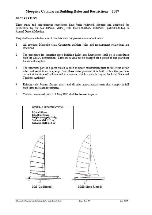
Mosquito Catamaran Building Rules and Restrictions – 2007DECLARATIONThese rules and measurement restrictions have been reviewed, adopted and approved for publication by the NATIONAL MOSQUITO CATAMARAN COUNCIL (AUSTRALIA) in Annual General Meeting.They shall come into force as of this date with the provisions as set out below:1 All previous Mosquito class Catamaran building rules and measurement restrictions arerescinded.2 The procedure for changing these Building Rules and Restrictions shall be in accordancewith the NMCC constitution. These rules shall not be changed for a period of one year from the date of adoption.3 The structural part of a yacht which is built or under construction prior to this issue of therules and restrictions is exempt from these rules provided it is built within the practices current at the time of building and in a manner which is satisfactory to the Local State and Territory Authority.4 Existing sails, booms, fittings, masts and all other non-structural parts shall comply in fullwith these rules and restrictions.5 Yachts commenced prior to 1 May 1975 shall be deemed imperial.MkI (Cat Rigged) MkII (Sloop Rigged) GENERAL SPECIFICATIONS LOA: 4900 mm BEAM: 2185 mmWeight (unrigged): 55 kg Sail Area MkI: 12.5 m 2 Sail Area MkII: 14.9 m 2TABLE OF CONTENTS1 General2 Registration3 Measurement - General4 Recognition Marks5 Measurement - Hulls6 Beams7 Trampoline8 Centreboards9 Rudders10 Weight11 Mast12 Boom13 Standing rigging14 Sails15 'Black bands'16 Mainsheet traveller17 Hiking aids18 Prohibited fittings19 De-restrictions20 Safety Requirements21 Spinnaker1 GENERAL1.1 The National Mosquito Catamaran Council (Australia) does not accept legal responsibility inrespect of these rules or any claim arising there from.1.2 A Mosquito Catamaran is a restricted class which can be sailed in two modes; Mark I (catrigged, one person) or Mark II (sloop rigged, two persons). To sail competitively in class racing a boat shall comply with class rules. These rules take precedence over measurement forms and plans.1.3 The object of these restrictions is to provide uniform specifications and restrictions for theabove class and are to be read in conjunction with the plans.1.4 Where there is no State or Territory Authority, its function as stated in these rules shall becarried out by the National Mosquito Catamaran Council (Australia), or its delegated representatives.2 REGISTRATION2.1 No boat shall be allowed to race in the Class unless it has a valid Class MeasurementCertificate.Application for measurement and registration shall be the responsibility of the owner, who shall apply to the appropriate authority, submitting at the same time the proposed name of the boat and sail number. No two boats in the Class registered in the same State shall have the same name.2.2 The owner shall arrange the attendance of an approved Measurer who shall complete themeasurement form and, if satisfied, shall certify thereon that the boat complies with the Class rules and the current AYF safety prescriptions.2.3 The measurement form, when complete, shall be returned by the owner to his StateAuthority, together with any measurement fee required. On receipt of these a measurement certificate shall be issued to the owner. The State Authority shall then enter the boat on its official Class Register. Each time a boat is submitted for measurement a fee shall be charged.2.4 Change of ownership invalidates the certificate but re-registration may be effected byreturning the old certificate to the State Authority, together with an application in writing containing the name and address of the new owner and the appropriate re-registration fee if any. Re-measurement is not necessary.The State Authority shall issue a new certificate to the owner, and amend its Class Register accordingly.2.5 The boat is defined as a pair of hulls. The registered sail number applies to that pair of hulls.A hull may be replaced because of serious damage but is subject to measurement. A newpair of hulls, for any reason, constitutes a new boat and as such requires a new sail number.3 MEASUREMENT - GENERAL3.1 This is a restricted class. Measurement tolerances are intended to allow for genuine errorsonly and shall not be deliberately used to alter the design. The measurer may report on the measurement form anything which he considers departs from the intended nature and design of the boat, or to be against the general interest of the Class.3.2 Only an official measurer appointed by the National or State Authority shall measure a boatand sign the declaration on the measurement form that it complies with the Class Rules.3.3 A measurer shall not measure a boat owned or built by himself.3.4 It shall be the responsibility of the owner to see that the boat is correctly measured and toensure that it thereafter complies with the current Class Rules.3.5 All certified boats shall be liable to re-measurement at the discretion of the NationalAuthority, State or Territory Authority, or Race Committee, but only by an official measurer.Any boat re-measured at a Class Meeting and found not to comply with the Class Rules may be disqualified by protest.3.6 A certificate may be invalidated by structural alteration, replacement of components or repairof the boat and the boat shall be re-measured in respect of the affected parts by an official measurer.3.7 New sails shall be measured, and registered on the Class Measurement Certificate by anofficial measurer.3.8 Completed hulls must comply with these restrictions in all respects but, at the builder'sdiscretion, may differ from the internal specifications outlined in the plans.3.9 Builders shall be classified as either amateur or professional. To retain amateur status,builders shall be restricted to the construction of one pair of hulls per annum. Professional builders shall be required to gain registration with their State or Territory Authority before marketing their hulls. To be eligible for registration a builder shall have produced at least one prototype boat in sloop rigged configuration and shall have had it complete without structural damage at least four races in conditions of more than 20 knots and 1.5 metre seas.3.10 Professional builders shall not be involved with voting on the registration of other builders inthis rule.4 RECOGNITION MARKS4.1 The yacht's registered number shall be permanently marked, legible and easily visible to therear face of the rear beam port side.4.2 The sail numbers and class emblem shall be placed on both sides of the mainsail, inaccordance with current ISAF rules and Yachting Australia prescriptions.4.3 The numbers and emblems shall sharply contrast in colour with the sail. Letters and numberson the sail shall be of the following minimum sizes:∙height 300 mm ± 15 mm∙width 200 mm ± 15 mm (except Figure 1 and Letter I)∙thickness 45 mm ± 5 mm.5 MEASUREMENT - HULLS5.1 Each hull shall be symmetrical.5.2 The bow shall be the datum point for all longitudinal measurements.DimensionsMeasured to:5.2.1 Centre line of forward chainplates 900 mm minimum; 930 mm maximum;5.2.2 Forward edge of main beam 2250 mm minimum; 2300 mm maximum;5.2.3 Centre line of side stay chainplates 2780 mm minimum; 2860 mm maximum;5.2.4 Forward edge of centreplate case 2860 mm minimum;5.2.5 Aft edge of centreplate case 3353 mm maximum;5.2.6 Forward edge of rear beam 4380 mm minimum; 4440 mm maximum.5.3 Overall length 4900 mm maximum. The length of the hull shall be measured in a straightline along the tops of the main and rear beams, measuring between two perpendiculars to this line which just touch the tip of the bow and the aftermost point of the transom respectively.5.4 Overall width (i.e. maximum beam) 2185 mm. The beam is considered inclusive of anyfittings and fixtures on the hulls.5.5 The deck widths and hull girths, including deck and hull curves respectively shall bemeasured between the inner and outer sheer lines at the following points on both hulls: `The sheer line is the intersection of the deck and the side of the hull and does not include "anti-slip systems" placed on the gunwales to achieve hull width dimensions.'5.5.1 Forward edge of main beam∙deck width 345 mm ± 5 mm∙hull girth 1065 mm ± 25 mm5.5.2 Aft edge of rear beam∙deck width 355 mm ± 5 mm∙hull girth 800 mm ± 25 mm.5.6 The bow profile shall be as per plan ± 20% on measurement from bow datum line labelled onPlan Sheet 1.5.7 The transom profile shall be as per plan ± 5 mm. This does not include the hull sides andrear deck thickness as indicated by the dotted line on the transom profile.5.8 The hull cross-sectional profile shall fit within the measuring templates and shall touch thekeel line. The templates shall be located at right angles to the deck line at the following positions:∙Beneath the forward edge of the front chain plate.∙Beneath the forward edge of the main beam.∙Beneath the after edge of the rear beam.5.9 The longitudinal profile of the deck shall fall within the tolerance determined by measuringtemplates placed on the deck immediately forward of the front beam and aft of the rear beam.Sighting from behind the transom, the tip of the bow shall be not less than 100 mm below the line of sight between the centre lines of the template.5.10 Materials used in hull and deck construction are optional.5.11 The leading and trailing edges of the centreboard slots shall be parallel and within 10o of theperpendicular from a straight line along the tops of the main and rear beams.5.12 The method of construction of timber Mosquito hulls is optional. The hull sides shall have afair curve from top to bottom. When viewed from bow to stern, the sheer line of the deck shall not be concave between the deck measurement points, except for fittings and beam recesses.5.13 The deck curvature shall be within 5 mm of the deck template as drawn on the plan but thegunwale may be radiused to a maximum of 3 mm.6 BEAMS6.1 The hulls shall be joined by a main beam and rear beam which shall each be in onecontinuous piece. There shall be no beam or strut attached to the hulls other than the main beam and rear beam.The main beam and rear beam shall each be of straight aluminium alloy of constant section along its length. Holes may be drilled in the beams for fastenings only. Holes remaining after the removal of redundant fittings are permitted.6.2 The main and rear beam shall be; a rectangular hollow section 50 mm plus or minus 1 mm by39 mm plus or minus 1 mm by minimum 3 mm wall. Beam edges may be rounded to amaximum of 2 mm radius.6.3 There shall be no fairings fitted to the beams.6.4 The main beam shall be fitted with a strut and tie as per drawing. The leading edge of the tiemay be rounded, but not sharpened, to not more than 5 mm from the leading edge. The strut shall be of circular cross-section of diameter not less than 21 mm and minimum length 152 mm. The tie shall be of stainless steel and shall have the following minimum dimensions:∙width 35 mm∙thickness 3 mm(as per plan drawing).6.5 The central beam shall be 50 mm diameter x 1.5 mm wall thickness, or 50 mm square x 1.5mm wall thickness (with rounded corners).6.6 All beam fastenings shall be marine grade stainless, monel or aluminium. Lightening holesare not permitted in any part of the beams.6.7 The main and rear beams shall be inserted into their beam boxes with the …x‟ axis of thebeam-section mounted perpendicular to the hull sheer line. When measured at the beam datum point, beam penetration into the hull must be equal at the inner and outer sheer lines and not exceed 6mm below the sheer line. (This does not include the striker strap.) See Rule5.5 for the definition of the sheer line. The …x‟ axis is the longer dimension of the rectangularbeam section7 TRAMPOLINE7.1 The trampoline shall not extend beyond the front and rear beams or past the centreline of thedecks.7.2 The method of attachment is optional.7.3 Net trampoline materials are prohibited.8 CENTREBOARDS8.1 Two centreboards shall be fitted, one per hull.8.2 The centreboards shall have no moving parts except that uphaul/downhaul cords and latchesare allowed.8.3 Lightening holes are allowed in that part of the centreboard enclosed by the centrecase whenthe centreboard is in the fully down position.8.4 The maximum length shall be 1220 mm. The maximum width shall be 305 mm. Thethickness of the centreboards shall be 22 mm ± 2 mm. Width and thickness measurements are to be taken on that part of the board enclosed in the centreplate case when the board is fully inserted.9 RUDDERS9.1 The rudder boxes are to be held captive to the transoms to prevent loss due to capsize.9.2 With the rudders in the fore-and-aft position the centre planes of each hull and its ruddershall coincide.10 WEIGHT10.1 The total weight of the assembled hulls shall not be less than 55 kg when in dry condition tothe measurer's satisfaction. The assembled hulls may include the following items:∙The hulls including anti-skid material∙Main beam, rear beam, centre beam∙Mast step and main beam strut and tie∙Trampoline and attachments for fitting to beam and hulls∙Chainplates and rudder gudgeons∙Mainsheet traveller track or hawse, car and associated control devices (excluding rope) ∙Jib track, hawse and barber-hauler systems∙Centre-board control fittings∙All shock cords and fittings used for attachment of trapeze systems to the platform∙Hatch-cover mounting bases∙Toe straps, foot straps and bracing lines∙All fixed mounting plates and brackets∙All fasteners (e.g. bolts, rivets, screws) for securing the above∙CorrectorsAny items not listed above shall be excluded.No other fittings or equipment shall be included in the minimum weight. Any permanently attached fittings in addition to the above shall be described (with weight stated) on the measurement certificate and duly endorsed by the State Measurer. Allowance for this endorsed weight shall be made at any State or National weighing.10.2 The correctors shall be made of a solid material and when fitted shall be fixed in a visiblelocation. They shall have no purpose other than to increase the weight of the boat to the minimum figure specified in clause 10.1.10.3 If correctors are altered or removed, the boat shall be re-weighed by an official measurer anda new certificate obtained.11 MAST11.1 The mast shall be made of an extruded aluminium alloy.11.2 The maximum height of the top of the mast including all permanent fittings shall not begreater than 7360 mm above the top of the main beam.11.3 The forestay attachment point shall be 5280 mm ± 100 mm from the top of the main beam. Ifmore than one potential forestay attachment point is provided then all such points shall fall within the measurement tolerance.11.4 Section size:∙width 59 mm min; 63 mm max.∙depth 86 mm min; 91 mm max.11.5 Tapered mast permitted, but when used tapering shall only be above the 5180 mm mark. 11.6 Mast rotation control must be fitted.12 BOOM12.1 The boom may be of any material, but shall be inherently straight and of constant sectionthroughout its length.12.2 Excluding fittings the boom shall pass through an 80 mm diameter circle.12.3 Maximum length shall be 2800 mm measured along the length of boom from the back of themast track to the end of the boom or outhaul fittings.13 STANDING RIGGING13.1 The standing rigging shall consist of the shrouds, the forestay(s), the forestay strop and thediamond stays.13.2 There shall be one shroud to each hull, the attachment point being on the outer top-sides. 13.3 The mast shall carry one pair of diamond stays only, which shall be rigged below the hounds.13.4 On Mark II yachts there shall be one forestay only which shall be attached to a strop betweenthe hulls, but twin forestays may be fitted on Mark I yachts.13.5 The bridle height shall be a minimum of 380 mm above the deck line. The measurement willbe a vertical measurement to the centre of the bridle ring from a straight edge laid across the decks at the bridle attachment points.13.6 Struts, stays or devices which limit the natural fore and aft movement of the forestay andforestay strop are prohibited (jib luff tension device excluded).13.7 There shall be no other standing rigging.13.8 All standing rigging shall be circular in section, minimum diameter 3 mm, and shall have nofairings.13.9 Adjusting the standing rigging whilst racing is prohibited, except that diamond stays may beadjusted.14 SAILS14.1 The rig shall consist of mainsail and foresail for Mark II or mainsail only for Mark I exceptwhen a spinnaker is being used as per item 21. The current ISAF Equipment Rules of Sailing shall apply where no conflict with these rules arises.14.2 Removable battens shall be removed from the sails for measurement. Sails shall be measuredon a flat surface. Just sufficient tension shall be applied to remove waves and wrinkles at the lines of measurement. The leech shall have no hollows having the effect of increasing the sail area.14.3 Foresail14.3.1 A maximum of three foresail battens is allowed, in the leech only. Each batten shall be nomore than 300 mm in length and 50 mm in width.14.3.2 The jib shall either use hanks, a stitched double luff, zipper luff, nylon foil or otherapproved devices to attach it to the forestay. If a foil is used then this must be treated as part of the sail for measuring purposes.14.3.3 The length of the luff shall not be more than 4120 mm.The length of the leech shall be not more than 3810 mm.The length of the foot shall not be more than 1680 mm.The maximum foot round shall be 100 mm.14.3.4 At the half leech point the nearest point of the luff shall be not more than 790 mm.The half leech point shall be found by folding the head to the clew and smoothing the sail out flat.14.3.5 The head of the sail shall not exceed 50mm.14.3.6 The leech in no area shall be convex and must be a fair curve.Foresail Measurement Diagram14.4 Mainsail14.4.1 The sail shall be loose footed and shall be attached to the boom or fittings at or near thetack and clew only.14.4.2 There shall be a maximum of eight battens from the leech to the luff. There shall be noother battens and no batten may extend more than 100 mm beyond the leech of the sail. 14.4.3 A headboard is optional and when used shall not exceed 120 mm in height or width.14.4.4 The sail shall be hoisted within the integral luff groove of the mast extrusion, and shallnot be fitted with a sleeve, double luff or other fairing device. The head of the mainsail shall not extend beyond the top of the mast.14.4.5 All cross measurements are taken to include the bolt rope. All cross measurements aretaken to the nearest point on the luff with the exception of dimension `A'.Dimension `A' is found by swinging an arc with a radius of 845 mm from the head of the sail to intersect the leech and the luff. The straight line intersecting these two shall be not greater than 750 mm.Mainsail Measurement Diagram15 `BLACK BANDS'15.1 A system of `black bands' 25 mm wide of a colour contrasting with that of the mast and boomshall be used on the spars to mark the limits of extension of the mail sail's length along its luff and foot.15.2 Two bands shall be painted in any position on the mast with their inner edges 6900 mm apart,except when the mainsail is set to the mast head in which case only one band shall be used, with its upper edge positioned 6900 mm below the top of the mast.15.3 One band only shall be painted on the boom with its inner edge 2550 mm (measured alongthe length of boom) from the aft edge of the mast track or its extension.15.4 When the mainsail is set on its spar the luff and foot shall be wholly contained within theinner edges of the bands.16 MAINSHEET TRAVELLERThe mainsheet traveller track shall be straight along the rear beam. The type of traveller is optional.17 HIKING AIDSFoot loops, blocks, toe straps, anti-slip surface treatment, trapeze gear and bracing lines are permitted. No other aids are allowed.18 PROHIBITED FITTINGS18.1 Hydrofoils, outriggers, ballast, suction bailers, keel bands except in the way of centreboardslot, rubbing stakes, spray deflectors, chines, and any projection from the skin other than normal fittings.18.2 Any device not called for in the plans and restrictions and not de-restricted in Item 19.18.3 Weight belts of any description.19 DE-RESTRICTIONSOnly items in the following list may deviate from the plan in the manner described.∙Position of ports in deck.∙Fittings - type and manufacture of all fittings.∙Mast rotation control.∙Rudders, tillers and associated mechanisms.∙Whisker pole.∙Wind indicators.∙Number of trapezes.∙Boom vang - circular track shall have a pitch circle diameter not greater than 0.7 m.∙Leech lines.∙Shape of centreboards - within the limits of section 8.∙Jib and mainsheet arrangement and fittings.∙Jib and main luff tensioning devices.20 SAFETY REQUIREMENTSBoats shall comply with current safety regulations of the Australian Yachting Federation.21 SPINNAKEREither the NMCC or a state authority may choose to run an event in which the use of a spinnaker is permitted, in which case this rule shall apply. This rule also applies to Mosquito class boats sailing with a spinnaker at any other events.21.1 The spinnaker pole shall be attached to the centre of the main beam, and shall be fixed in afore and aft position.21.2 No part of the spinnaker pole or its fittings may extend more than 3030 mm from the front ofthe main beam.21.3 The head of the spinnaker shall not be hoisted more than 6380 mm from the top of the mainbeam.21.4 The maximum luff length shall be 6950 mm.21.5 The maximum foot length shall be 3500 mm.CHANGE HISTORYTHIS SECTION DOES NOT FORM PART OF THE BUILDING RULES AND RESTRICTIONS Versions1 July 1997 Peter Hallsworth National Technical Officer1 April 2000 Roger Wilson National Secretary10 January 2001 Ross Bennett National Technical Officer3 January 2007 Tim Shepperd National Technical Officer Accepted at Annual General Meeting, 11th January 2000:14.3 ForesailReplace:14.3.3 The foresail must lie totally within a triangle drawn to themaximum measurements adjacent, but excluding the footround.Luff 4120 mmLeech 3810 mmFoot 1680 mmFoot round 100 mmBy:14.3.3 The length of the luff shall not be more than 4120mm. Thelength of the leech shall not be more than 3810mm. Thelength of the foot shall not be more than 1680mm. Themaximum foot round shall be 100mm.14.3.4 At the half leech point the nearest point on the luff shall notbe more than 790mm. The half leech point shall be foundby folding the head to the clew and smoothing the sail outflat.14.3.5 The head of the sail shall not exceed 50mm.14.3.6 The leech in no area shall be convex and must be a faircurve.APPENDIX 1 _PROCEDURE FOR ALTERATION TO PLANS, BUILDING RULES ANDRESTRICTIONSReplace the following clauses:Any such motion of alteration shall then be circulated to other State Associations at least three months prior to the National Annual General Meeting to allow time for adequate discussion of the proposed alteration. The method of voting on motions received from interstate shall be at the discretion of each association but a postal vote or special general meeting (to involve all members) is recommended.Voting at the National Annual General Meeting shall be by State Delegate who shall be accorded one vote for every 20 (or part thereof) currently financial members of his/her State Association.A two-thirds majority of the votes shall be required for the proposal to be accepted, where upon it shall apply from 1st July after the Annual General Meeting.By:Any such motion of alteration shall then be circulated to other State Associations at least three months prior a National General Meeting to allow time for adequate discussion of the proposed alteration. The method of voting on motions received from interstate shall be at the discretion of each association but a postal vote or special general meeting (to involve all members) is recommended.Voting at the National General Meeting shall be by State Delegate who shall be accorded one vote for every20 (or part thereof) currently financial members of his/her State Association.A two-thirds majority of the votes shall be required for the proposal to be accepted, where upon it shall apply from a date specified in the proposal or, if no date is specified, from 3 months after the date of the National General Meeting.MEASUREMENT _ HULLSCurrent Restriction:5.12 The method of construction of timber Mosquito hulls is optional. The hull sides shall have a fair curve from top to bottom.Proposal:5.12Add the following wording:“When viewed from bow to stern, the sheer line of the deck shall not be concave between the deck measurement points.AGM: Add “except for fittings and beam recesses”Explanation: (none)BEAMSCurrent Restriction:NOT APPLICABLEProposal:Add new 6.7 as follows:6.7 The main and rear beams shall be inserted into their beam boxes with the …x‟ axis of the beam-section mounted perpendicular to the hull sheer line. When measured at the beam datum point, beam penetration into the hull must be equal at the inner and outer sheer lines and not exceed 6mm below the sheer line. (This does not include the striker strap.) See Rule 5.5 for the definition of the sheer line.AGM: Add clarification on meaning of …x‟ axis.Explanation: The main and rear beams are a rectangular hollow section. The larger dimension of the section is frequently referred to as its …x‟-axis. The intention of this new rule is to ensure the x-dimension is as close to vertical as possible in future boats as in the original plans. This will prevent laying the beams “flat”. It will also prevent tilting the beams.It will prevent inserting the beams deep into the hulls with their top level with the deck. It will also prevent inserting the beams into the hulls in such a way that the hulls are canted off the vertical alignment.MAINSAILCurrent Restriction:14.4.3 The headboard shall not exceed 120 mm in height or width.Proposal:Alter the wording of 14.4.3 as follows:14.4.3 A headboard is optional and when used shall not exceed 120 mm in height or width.Explanation: During the 1999-2000 nationals much debate occurred if the Mosquito mainsail required a headboard. Current Rule 14.4.3 states maximum sizes for one but does not state one has to exist. The intention of this proposed rule change is to restrict the head size and then allow the sailmaker and customer to decide on the construction of the head using the latest materials and methods.。

FOREWORDThe first broadly recognized national standard for the design and construction of bridges in the United States was published in 1931 by the American Association of State Highway Officials (AASHO), the predecessor to AASHTO. With the advent of the automobile and the establishment of highway departments in all of the American states dating back to just before the turn of the century, the design, construction, and maintenance of most U.S. bridges was the responsibility of these departments and, more specifically, the chief bridge engineer within each department. It was natural, therefore, that these engineers, acting collectively as the AASHTO Highway Subcommittee on Bridges and Structures (now the Committee on Bridges and Structures), would become the author and guardian of this first bridge standard.This first publication was entitled Standard Specifications for Highway Bridges and Incidental Structures. It quickly became the de facto national standard and, as such, was adopted and used by not only the state highway departments but also other bridge-owning authorities and agencies in the United States and abroad. Rather early on, the last three words of the original title were dropped and it has been reissued in consecutive editions at approximately four-year intervals ever since as Standard Specifications for Highway Bridges, with the final 17th edition appearing in 2002.The body of knowledge related to the design of highway bridges has grown enormously since 1931 and continues to do so. Theory and practice have evolved greatly, reflecting advances through research in understanding the properties of materials, in improved materials, in more rational and accurate analysis of structural behavior, in the advent of computers and rapidly advancing computer technology, in the study of external events representing particular hazards to bridges such as seismic events and stream scour, and in many other areas. The pace of advances in these areas has, if anything, stepped up in recent years.In 1986, the Subcommittee submitted a request to the AASHTO Standing Committee on Research to undertake an assessment of U.S. bridge design specifications, to review foreign design specifications and codes, to consider design philosophies alternative to those underlying the Standard Specifications, and to render recommendations based on these investigations. This work was accomplished under the National Cooperative Highway Research Program (NCHRP), an applied research program directed by the AASHTO Standing Committee on Research and administered on behalf of AASHTO by the Transportation Research Board (TRB). The work was completed in 1987, and, as might be expected with a standard incrementally adjusted over the years, the Standard Specifications were judged to include discernible gaps, inconsistencies, and even some conflicts. Beyond this, the specification did not reflect or incorporate the most recently developing design philosophy, load-and-resistance factor design (LRFD), a philosophy which has been gaining ground in other areas of structural engineering and in other parts of the world such as Canada and Europe.From its inception until the early 1970s, the sole design philosophy embedded within the Standard Specifications was one known as working stress design (WSD). WSD establishes allowable stresses as a fraction or percentage of a given material’s load-carrying capacity, and requires that calculated design stresses not exceed those allowable stresses. Beginning in the early 1970s, WSD began to be adjusted to reflect the variable predictability of certain load types, such as vehicular loads and wind forces, through adjusting design factors, a design philosophy referred to as load factor design (LFD).A further philosophical extension results from considering the variability in the properties of structural elements, in similar fashion to load variabilities. While considered to a limited extent in LFD, the design philosophy of load-and-resistance factor design (LRFD) takes variability in the behavior of structural elements into account in an explicit manner. LRFD relies on extensive use of statistical methods, but sets forth the results in a manner readily usable by bridge designers and analysts.Starting with the Eighth Edition of the AASHTO LRFD Bridge Design Specifications, interim changes to the Specifications were discontinued, and new editions are published on a three-year cycle. Changes are balloted and approved by at least two-thirds of the members of the Committee on Bridges and Structures. AASHTO members include the 50 State Highway or Transportation Departments, the District of Columbia, and Puerto Rico. Each member has one vote. The U.S. Department of Transportation is a non-voting member.Orders for Specifications may be placed by visiting the AASHTO Store, ; calling the AASHTO Publication Sales Office toll free (within the U.S. and Canada), 1-800-231-3475; or mailing to P.O. Box 933538, Atlanta, GA 31193-3538. A free copy of the current publication catalog can be downloaded from the AASHTO Store.For additional publications prepared and published by the Committee on Bridges and Structures and by other AASHTO Committees, please look online in the AASHTO Store () under “Bridges and Structures.”Suggestions for the improvement of the AASHTO LRFD Bridge Design Specifications are welcomed, just as they were for the Standard Specifications for Highway Bridges before them, at .The following have served as chair of the Committee on Bridges and Structures since its inception in 1921: E. F. Kelley, who pioneered the work of the Committee; Albin L. Gemeny; R. B. McMinn; Raymond Archiband; G. S. Paxson;E. M. Johnson; Ward Goodman; Charles Matlock; Joseph S. Jones; Sidney Poleynard; Jack Freidenrich; Henry W. Derthick; Robert C. Cassano; Clellon Loveall; James E. Siebels; David Pope; Tom Lulay; Malcolm T. Kerley; Gregg Fredrick; and Carmen Swanwick. The Committee expresses its sincere appreciation of the work of these individuals and of those active members of the past, whose names, because of retirement, are no longer on the roll.The Committee would also like to thank John M. Kulicki, Ph.D., and his associates at Modjeski and Masters for their valuable assistance in the preparation of the AASHTO LRFD Bridge Design Specifications.PREFACE ANDABBREVIATED TABLE OF CONTENTSThe AASHTO LRFD Bridge Design Specifications, Ninth Edition contains the following 15 sections and an index:1.Introduction2.General Design and Location Features3.Loads and Load Factors4.Structural Analysis and Evaluation5.Concrete Structures6.Steel Structures7.Aluminum Structures8.Wood Structures9.Decks and Deck Systems10.Foundations11.Abutments, Piers, and Walls12.Buried Structures and Tunnel Liners13.Railings14.Joints and Bearings15.Design of Sound BarriersIndexDetailed Tables of Contents precede each section. The last article of each section is a list of references displayed alphabetically by author.Figures, tables, and equations are denoted by their home article number and an extension, for example 1.2.3.4.5-1 wherever they are cited. In early editions, when they were referenced in their home article or its commentary, these objects were identified only by the extension. For example, in Article 1.2.3.4.5, Eq. 1.2.3.4.5-2 would simply have been called “Eq. 2.” The same convention applies to figures and tables. Starting with this edition, these objects are identified by their whole nomenclature throughout the text, even within their home articles. This change was to increase the speed and accuracy of electronic production (i.e., CDs and downloadable files) with regard to linking citations to objects.Please note that the AASHTO materials standards (starting with M or T) cited throughout the LRFD Bridge Design Specifications can be found in Standard Specifications for Transportation Materials and Methods of Sampling and Testing,adopted by the AASHTO Highway Subcommittee on Materials. The individual standards are also available as downloads on the AASHTO Store, https://. Unless otherwise indicated, these citations refer to the current edition. ASTM materials specifications are also cited and have been updated to reflect ASTM’s revised coding system, i.e., spaces removed between the letter and number.CHANGED AND DELETED ARTICLES,2020SUMMARY OF AFFECTED SECTIONSThe revisions included in the AASHTO LRFD Bridge Design Specifications, Ninth Edition affect the following sections: 1.Introduction3.Loads and Load Factors4.Structural Analysis and Evaluation5.Concrete Structures6.Steel Structures8.Wood Structures10.Foundations11.Walls, Abutments, and Piers12.Buried Structures and Tunnel Liners15.Design of Sound BarriersSECTION 1 REVISIONSChanged ArticlesThe following Articles in Section 1 contain changes or additions to the specifications, the commentary, or both: 1.3.5Deleted ArticlesNo Articles were deleted from Section 1.SECTION 3 REVISIONSChanged ArticlesThe following Articles in Section 3 contain changes or additions to the specifications, the commentary, or both:3.3.1 3.4.1 3.6.1.2.6a3.6.5.13.6.5.23.11.5.43.11.5.63.11.5.8.23.11.5.93.16Deleted ArticlesNo Articles were deleted from Section 3.SECTION 4 REVISIONSChanged ArticlesThe following Articles in Section 4 contain changes or additions to the specifications, the commentary, or both: 4.5.3.2.2b 4.6.2.2.1 4.6.2.2.2b 4.6.2.10.2 4.9 Deleted ArticlesNo Articles were deleted from Section 4.SECTION 5 REVISIONSChanged ArticlesThe following Articles in Section 5 contain changes or additions to the specifications, the commentary, or both:5.3 5.4.3.1 5.4.6.2 5.5.3.1 5.5.4.3 5.7.2.15.7.2.85.7.3.35.7.3.55.7.3.6.25.8.4.3.55.9.4.3.35.9.4.55.9.5.6.15.10.15.10.4.35.10.8.2.55.10.8.5.15.10.8.5.25.12.3.2.15.12.9.5.25.14.15.14.45.15Deleted ArticlesNo Articles were deleted from Section 5.SECTION 6 REVISIONSChanged ArticlesThe following Articles in Section 6 contain changes or additions to the specifications, the commentary, or both:6.1 6.2 6.3 6.4.9 6.5.3 6.5.4.2 6.5.5 6.6.1.2.3 6.6.1.2.5 6.6.2.1 6.6.2.2 6.7.2 6.7.4.3 6.7.4.4 6.7.4.4.1 6.7.4.4.2 6.7.4.4.3 6.7.4.5 6.7.8 6.8.2.2 6.8.2.3 6.8.2.3.1 6.8.2.3.2 6.8.2.3.3 6.8.6.2 6.9.2.2 6.9.2.2.1 6.9.2.2.2 6.9.4.1.1 6.9.4.1.26.9.4.1.36.9.4.26.9.4.2.16.9.4.2.26.9.4.2.2a6.9.4.2.2b6.9.4.2.2c6.9.4.3.16.9.4.46.9.4.56.9.6.16.9.6.26.10.1.1.1a6.10.1.46.10.1.10.16.10.1.10.26.10.2.26.10.3.36.10.3.4.16.10.3.4.26.10.5.26.10.6.16.10.6.2.36.10.8.1.16.10.8.2.36.10.8.36.10.9.16.10.10.26.10.116.10.11.16.10.11.1.16.10.11.2.26.10.11.2.4b6.10.11.36.10.11.3.16.10.11.3.36.116.11.1.16.11.3.26.11.56.11.6.2.16.11.8.2.26.11.8.36.12.16.12.1.16.12.1.2.16.12.1.2.26.12.1.2.36.12.1.2.3a6.12.1.2.3b6.12.1.2.46.12.26.12.2.16.12.2.2.26.12.2.2.2a6.12.2.2.2b6.12.2.2.2c6.12.2.2.2d6.12.2.2.2e6.12.2.2.2f6.12.2.2.2g6.12.2.2.36.12.2.2.4a6.12.2.2.4b6.12.2.2.4c6.12.2.2.4d6.12.2.2.4e6.12.2.2.56.12.2.3.36.12.3.2.26.13.2.3.26.13.2.56.13.2.76.13.2.96.13.2.10.26.13.2.116.13.3.66.13.3.76.13.6.1.3a6.13.6.1.3b6.13.6.1.3c6.13.6.1.46.14.2.46.14.4.16.14.4.26.14.4.36.14.4.46.14.4.56.14.4.66.16.16.16.26.16.4.16.17A6A6.1A6.2.1A6.2.2A6.3.3C6.4C6.4.4C6.4.7C6.5.1C6.5.2D6.2.1D6.3.1E6.1E6.1.1E6.1.2E6.1.3E6.1.4E6.1.5E6.1.5.1E6.1.5.2Deleted Articles 6.12.1.2.3cSECTION 8 REVISIONSChanged ArticlesThe following Articles in Section 8 contain changes or additions to the specifications, the commentary, or both:8.2 8.4.1.1.4 8.4.1.2.18.4.1.2.28.4.1.2.38.4.1.3.18.4.4.98.138.14Deleted ArticlesNo Articles were deleted from Section 8.SECTION 10 REVISIONSChanged ArticlesThe following Articles in Section 10 contain changes or additions to the specifications, the commentary, or both:10.3 10.5.2.1 10.5.2.2 10.5.2.2.1 10.5.2.2.2 10.5.2.4 10.5.3.110.5.5.110.5.5.2.110.6.2.110.6.2.4.110.6.2.4.2a10.6.2.4.2b10.6.2.4.2c10.6.2.4.410.6.3.1.2a10.6.3.1.2c10.6.3.2.110.6.3.510.7.2.110.7.3.110.7.810.8.3.5.1b10.8.3.5.2b10.9.3.5.410.10Deleted Articles10.5.2.3 10.6.2.5SECTION 11 REVISIONSChanged ArticlesThe following Articles in Section 11 contain changes or additions to the specifications, the commentary, or both:11.1 11.2 11.3.1 11.5.2 11.5.3 11.5.4.2 11.5.5 11.5.7 11.5.8 11.6.2 11.6.3.1 11.6.3.7 11.6.5.111.8.311.8.4.111.8.6.111.9.311.9.4.311.9.4.411.10.111.10.2.3.111.10.411.10.4.211.10.4.311.10.5.211.10.5.611.10.6.111.10.6.211.10.6.2.111.10.6.2.1a11.10.6.2.1b11.10.6.2.1c11.10.6.2.1d11.10.6.2.1e11.10.6.2.211.10.6.3.211.10.6.4.111.10.6.4.2a11.10.6.4.2b11.10.6.4.3b11.10.6.4.4a11.10.6.4.4b11.10.7.211.10.7.311.10.7.411.10.811.10.10.111.10.10.211.10.10.311.10.1111.11.4.611.1211.12.7.211.12.911.13A11.5.3B11.1B11.2B11.3Deleted Articles11.6.2.3 11.8.3.2 11.9.3.2SECTION 12 REVISIONSChanged ArticlesThe following Articles in Section 12 contain changes or additions to the specifications, the commentary, or both:12.1 12.2 12.4.2.3 12.4.2.10 12.5.412.6.412.6.912.7.2.112.7.2.712.8.5.312.8.9.3.112.10.112.10.2.112.10.4.3.112.12.2.112.12.3.512.12.3.10.2b12.16A12Deleted ArticlesNo Articles were deleted from Section 12.SECTION 15 REVISIONSChanged ArticlesThe following Articles in Section 15 contain changes or additions to the specifications, the commentary, or both:15.9.3 15.9.7 15.9.8Deleted Articles15.9.7.1AASHTO Publications StaffApril 2020S ECTION 1:I NTRODUCTIONTABLE OF CONTENTS1.1—SCOPE OF THE SPECIFICATIONS .................................................................................................................. 1-1 1.2—DEFINITIONS ..................................................................................................................................................... 1-2 1.3—DESIGN PHILOSOPHY ..................................................................................................................................... 1-31.3.1—General ....................................................................................................................................................... 1-31.3.2—Limit States ................................................................................................................................................ 1-31.3.2.1—General ............................................................................................................................................ 1-31.3.2.2—Service Limit State ........................................................................................................................... 1-41.3.2.3—Fatigue and Fracture Limit State ...................................................................................................... 1-41.3.2.4—Strength Limit State ......................................................................................................................... 1-41.3.2.5—Extreme Event Limit States ............................................................................................................. 1-51.3.3—Ductility ..................................................................................................................................................... 1-51.3.4—Redundancy ............................................................................................................................................... 1-61.3.5—Operational Importance ............................................................................................................................. 1-7 1.4—REFERENCES .................................................................................................................................................... 1-7S ECTION 2:G ENERAL D ESIGN AND L OCATION F EATURESTABLE OF CONTENTS2.1—SCOPE ................................................................................................................................................................. 2-1 2.2—DEFINITIONS ..................................................................................................................................................... 2-1 2.3—LOCATION FEATURES .................................................................................................................................... 2-32.3.1—Route Location ........................................................................................................................................... 2-32.3.1.1—General ............................................................................................................................................. 2-32.3.1.2—Waterway and Floodplain Crossings ............................................................................................... 2-32.3.2—Bridge Site Arrangement ........................................................................................................................... 2-42.3.2.1—General ............................................................................................................................................. 2-42.3.2.2—Traffic Safety ................................................................................................................................... 2-42.3.2.2.1—Protection of Structures ......................................................................................................... 2-42.3.2.2.2—Protection of Users ................................................................................................................ 2-42.3.2.2.3—Geometric Standards .............................................................................................................. 2-52.3.2.2.4—Road Surfaces ........................................................................................................................ 2-52.3.2.2.5—Vessel Collisions ................................................................................................................... 2-52.3.3—Clearances .................................................................................................................................................. 2-52.3.3.1—Navigational ..................................................................................................................................... 2-52.3.3.2—Highway Vertical ............................................................................................................................. 2-52.3.3.3—Highway Horizontal ......................................................................................................................... 2-62.3.3.4—Railroad Overpass ............................................................................................................................ 2-62.3.4—Environment ............................................................................................................................................... 2-7 2.4—FOUNDATION INVESTIGATION .................................................................................................................... 2-72.4.1—General ....................................................................................................................................................... 2-72.4.2—Topographic Studies .................................................................................................................................. 2-7 2.5—DESIGN OBJECTIVES ....................................................................................................................................... 2-72.5.1—Safety ......................................................................................................................................................... 2-72.5.1.1—Structural Survival ........................................................................................................................... 2-72.5.1.2—Limited Serviceability ...................................................................................................................... 2-72.5.1.3—Immediate Use ................................................................................................................................. 2-72.5.2—Serviceability ............................................................................................................................................. 2-82.5.2.1—Durability ......................................................................................................................................... 2-82.5.2.1.1—Materials ................................................................................................................................ 2-82.5.2.1.2—Self-Protecting Measures ....................................................................................................... 2-82.5.2.2—Inspectability .................................................................................................................................... 2-92.5.2.3—Maintainability ................................................................................................................................. 2-92.5.2.4—Rideability........................................................................................................................................ 2-92.5.2.5—Utilities ............................................................................................................................................ 2-92.5.2.6—Deformations ................................................................................................................................. 2-102.5.2.6.1—General ................................................................................................................................ 2-102.5.2.6.2—Criteria for Deflection .......................................................................................................... 2-112.5.2.6.3—Optional Criteria for Span-to-Depth Ratios ......................................................................... 2-132.5.2.7—Consideration of Future Widening ................................................................................................. 2-142.5.2.7.1—Exterior Beams on Girder System Bridges .......................................................................... 2-142.5.2.7.2—Substructure ......................................................................................................................... 2-142.5.3—Constructability ........................................................................................................................................ 2-142.5.4—Economy .................................................................................................................................................. 2-152.5.4.1—General ........................................................................................................................................... 2-152.5.4.2—Alternative Plans ............................................................................................................................ 2-152.5.5—Bridge Aesthetics ..................................................................................................................................... 2-15 2.6—HYDROLOGY AND HYDRAULICS .............................................................................................................. 2-172.6.1—General ..................................................................................................................................................... 2-172.6.2—Site Data ................................................................................................................................................... 2-182.6.3—Hydrologic Analysis ................................................................................................................................ 2-182.6.4—Hydraulic Analysis ................................................................................................................................... 2-192.6.4.1—General ........................................................................................................................................... 2-192-ii AASHTO LRFD B RIDGE D ESIGN S PECIFICATIONS,N INTH E DITION,20202.6.4.2—Stream Stability .............................................................................................................................. 2-192.6.4.3—Bridge Waterway ........................................................................................................................... 2-202.6.4.4—Bridge Foundations ........................................................................................................................ 2-202.6.4.4.1—General ................................................................................................................................. 2-202.6.4.4.2—Bridge Scour ........................................................................................................................ 2-212.6.4.5—Roadway Approaches to Bridge ..................................................................................................... 2-222.6.5—Culvert Location, Length, and Waterway Area ........................................................................................ 2-232.6.6—Roadway Drainage ................................................................................................................................... 2-232.6.6.1—General ........................................................................................................................................... 2-232.6.6.2—Design Storm .................................................................................................................................. 2-232.6.6.3—Type, Size, and Number of Drains ................................................................................................. 2-232.6.6.4—Discharge from Deck Drains .......................................................................................................... 2-242.6.6.5—Drainage of Structures .................................................................................................................... 2-24 2.7—BRIDGE SECURITY ......................................................................................................................................... 2-242.7.1—General ..................................................................................................................................................... 2-242.7.2—Design Demand ........................................................................................................................................ 2-25 2.8—REFERENCES ................................................................................................................................................... 2-25。

EUROPEAN COMMISSIONHEALTH AND CONSUMERS DIRECTORATE-GENERALHealth Systems and ProductsMedicinal Products - Quality, safety and efficacyBrussels,SANCO/AM/sl/ddg1.d.6(2012)860362EudraLexThe Rules Governing Medicinal Products in the European UnionVolume 4EU Guidelines forGood Manufacturing Practice forMedicinal Products for Human and Veterinary UseChapter 1Pharmaceutical Quality SystemLegal basis for publishing the detailed guidelines: Article 47 of Directive 2001/83/EC on the Community code relating to medicinal products for human use and Article 51 of Directive 2001/82/EC on the Community code relating to veterinary medicinal products. This document provides guidance for the interpretation of the principles and guidelines of good manufacturing practice (GMP) for medicinal products as laid down in Directive 2003/94/EC for medicinal products for human use and Directive 91/412/EEC for veterinary use.Status of the document: revision 3Reasons for changes: Amendments to the text of Chapter 1 have been made in order to align with the concepts and terminology described in the ICH Q10 tripartite guideline on Pharmaceutical Quality System. The title of the chapter itself is also changed accordingly.Deadline for coming into operation: 31 January 2013Commission Européenne, B-1049 Bruxelles / Europese Commissie, B-1049 Brussel – Belgium. Telephone: (32-2) 299 11 11PrincipleThe holder of a Manufacturing Authorisation must manufacture medicinal products so as to ensure that they are fit for their intended use, comply with the requirements of the Marketing Authorisation or Clinical Trial Authorisation, as appropriate and do not place patients at risk due to inadequate safety, quality or efficacy. The attainment of this quality objective is the responsibility of senior management and requires the participation and commitment by staff in many different departments and at all levels within the company, by the company’s suppliers and by its distributors. To achieve this quality objective reliably there must be a comprehensively designed and correctly implemented Pharmaceutical Quality System1 incorporating Good Manufacturing Practice and Quality Risk Management. It should be fully documented and its effectiveness monitored. All parts of the Pharmaceutical Quality System should be adequately resourced with competent personnel, and suitable and sufficient premises, equipment and facilities. There are additional legal responsibilities for the holder of the Manufacturing Authorisation and for the Qualified Person(s).The basic concepts of Quality Management, Good Manufacturing Practice and Quality Risk Management are inter-related. They are described here in order to emphasise their relationships and their fundamental importance to the production and control of medicinal products.Pharmaceutical Quality System11.1 Quality Management is a wide-ranging concept, which covers all matters, which individually or collectively influence the quality of a product. It is the sum total of the organised arrangements made with the objective of ensuring that medicinal products are of the quality required for their intended use. Quality Management therefore incorporates Good Manufacturing Practice.1.2 GMP applies to the lifecycle stages from the manufacture of investigational medicinal products, technology transfer, commercial manufacturing through to product discontinuation. However the Pharmaceutical Quality System can extend to the pharmaceutical development lifecycle stage as described in ICH Q10, which while optional, should facilitate innovation and continual improvement and strengthen the link between pharmaceutical development and manufacturing activities. ICH Q10 is reproduced in Part III of the Guide and can be used to supplement the contents of this chapter.1.3 The size and complexity of the company’s activities should be taken into consideration when developing a new Pharmaceutical Quality System or modifying an existing one. The design of the system should incorporate appropriate risk management principles including the use of appropriate tools. While some aspects of the system can be company-wide and others site-specific, the effectiveness of the system is normally demonstrated at the site level.1 Art 6 of Directives 2003/94/EC and 91/412/EEC require manufacturers to establish and implement an effective pharmaceutical quality assurance system. The term Pharmaceutical Quality System is used in this chapter in the interests of consistency withICH Q10 terminology. For the purposes of this chapter these terms can be considered interchangeable.1.4 A Pharmaceutical Quality System appropriate for the manufacture of medicinal products should ensure that:(i) Product realisation is achieved by designing, planning, implementing,maintaining and continuously improving a system that allows the consistent delivery of products with appropriate quality attributes;(ii) Product and process knowledge is managed throughout all lifecycle stages;(iii) Medicinal products are designed and developed in a way that takes account of the requirements of Good Manufacturing Practice;(iv) Production and control operations are clearly specified and Good Manufacturing Practice adopted;(v) Managerial responsibilities are clearly specified;(vi) Arrangements are made for the manufacture, supply and use of the correct starting and packaging materials, the selection and monitoring of suppliers and for verifying that each delivery is from the approved supply chain;(vii) Processes are in place to assure the management of outsourced activities.(viii) A state of control is established and maintained by developing and using effective monitoring and control systems for process performance and product quality.(ix) The results of product and processes monitoring are taken into account in batch release, in the investigation of deviations, and, with a view to taking preventive action to avoid potential deviations occurring in the future.(x) All necessary controls on intermediate products, and any other in-process controls and validations are carried out;(xi) Continual improvement is facilitated through the implementation of quality improvements appropriate to the current level of process and product knowledge.(xii) Arrangements are in place for the prospective evaluation of planned changes and their approval prior to implementation taking into account regulatory notification and approval where required;(xiii) After implementation of any change, an evaluation is undertaken to confirm the quality objectives were achieved and that there was no unintended deleterious impact on product quality;(xiv) An appropriate level of root cause analysis should be applied during the investigation of deviations, suspected product defects and other problems.This can be determined using Quality Risk Management principles. In caseswhere the true root cause(s) of the issue cannot be determined, considerationshould be given to identifying the most likely root cause(s) and to addressingthose. Where human error is suspected or identified as the cause, this shouldbe justified having taken care to ensure that process, procedural or system-based errors or problems have not been overlooked, if present. Appropriatecorrective actions and/or preventative actions (CAPAs) should be identifiedand taken in response to investigations. The effectiveness of such actionsshould be monitored and assessed, in line with Quality Risk Management principles.(xv) Medicinal products are not sold or supplied before a Qualified Person hascertified that each production batch has been produced and controlled in accordance with the requirements of the Marketing Authorisation and any other regulations relevant to the production, control and release of medicinalproducts;(xvi) Satisfactory arrangements exist to ensure, as far as possible, that themedicinal products are stored, distributed and subsequently handled so thatquality is maintained throughout their shelf life;(xvii) There is a process for self-inspection and/or quality audit, which regularly appraises the effectiveness and applicability of the PharmaceuticalQuality System.1.5 Senior management has the ultimate responsibility to ensure an effective Pharmaceutical Quality System is in place, adequately resourced and that roles, responsibilities, and authorities are defined, communicated and implemented throughout the organisation. Senior management’s leadership and active participation in the Pharmaceutical Quality System is essential. This leadership should ensure the support and commitment of staff at all levels and sites within the organisation to the Pharmaceutical Quality System.1.6 There should be periodic management review, with the involvement of senior management, of the operation of the Pharmaceutical Quality System to identify opportunities for continual improvement of products, processes and the system itself. 1.7 The Pharmaceutical Quality System should be defined and documented. A Quality Manual or equivalent documentation should be established and should contain a description of the quality management system including management responsibilities.Good Manufacturing Practice for Medicinal Products1.8 Good Manufacturing Practice is that part of Quality Management which ensures that products are consistently produced and controlled to the quality standards appropriate to their intended use and as required by the Marketing Authorisation, Clinical Trial Authorisation or product specification. Good Manufacturing Practice is concerned with both production and quality control. The basic requirements of GMP are that:(i) All manufacturing processes are clearly defined, systematically reviewed inthe light of experience and shown to be capable of consistently manufacturingmedicinal products of the required quality and complying with their specifications;(ii) Critical steps of manufacturing processes and significant changes to the process are validated;(iii) All necessary facilities for GMP are provided including:• Appropriately qualified and trained personnel;• Adequate premises and space;• Suitable equipment and services;• Correct materials, containers and labels;• Approved procedures and instructions, in accordance with thePharmaceutical Quality System;• Suitable storage and transport;(iv) Instructions and procedures are written in an instructional form in clear and unambiguous language, specifically applicable to the facilities provided;(v) Procedures are carried out correctly and operators are trained to do so;(vi) Records are made, manually and/or by recording instruments, during manufacture which demonstrate that all the steps required by the defined procedures and instructions were in fact taken and that the quantity and quality of the product was as expected.(vii) Any significant deviations are fully recorded, investigated with the objective of determining the root cause and appropriate corrective and preventive action implemented;(viii) Records of manufacture including distribution which enable the complete history of a batch to be traced are retained in a comprehensible and accessible form;(ix) The distribution of the products minimises any risk to their quality and takes account of Good Distribution Practice;(x) A system is available to recall any batch of product, from sale or supply;(xi) Complaints about products are examined, the causes of quality defects investigated and appropriate measures taken in respect of the defective products and to prevent reoccurrence.Quality Control1.9 Quality Control is that part of Good Manufacturing Practice which is concerned with sampling, specifications and testing, and with the organisation, documentation and release procedures which ensure that the necessary and relevant tests are actually carried out and that materials are not released for use, nor products released for sale orsupply, until their quality has been judged to be satisfactory. The basic requirements of Quality Control are that:(i) Adequate facilities, trained personnel and approved procedures areavailable for sampling and testing starting materials, packaging materials,intermediate, bulk, and finished products, and where appropriate for monitoring environmental conditions for GMP purposes;(ii) Samples of starting materials, packaging materials, intermediate products, bulk products and finished products are taken by approved personnel and methods;(iii) Test methods are validated;(iv) Records are made, manually and/or by recording instruments, which demonstrate that all the required sampling, inspecting and testing procedures were actually carried out. Any deviations are fully recorded and investigated;(v) The finished products contain active ingredients complying with the qualitative and quantitative composition of the Marketing Authorisation or clinical trial authorisation, are of the purity required, and are enclosed within their proper containers and correctly labelled;(vi) Records are made of the results of inspection and that testing of materials,intermediate, bulk, and finished products is formally assessed against specification. Product assessment includes a review and evaluation of relevant production documentation and an assessment of deviations from specified procedures;(vii) No batch of product is released for sale or supply prior to certification bya Qualified Person that it is in accordance with the requirements of therelevant authorisations in accordance with annex 16;(viii) Sufficient reference samples of starting materials and products are retained in accordance with Annex 19 to permit future examination of the product if necessary and that the sample is retained in the final pack.Product Quality Review1.10 Regular periodic or rolling quality reviews of all authorised medicinal products, including export only products, should be conducted with the objective of verifying the consistency of the existing process, the appropriateness of current specifications for both starting materials and finished product, to highlight any trends and to identify product and process improvements. Such reviews should normally be conducted and documented annually, taking into account previous reviews, and should include at least:(i) A review of starting materials including packaging materials used in theproduct, especially those from new sources and in particular the review ofsupply chain traceability of active substances.(ii) A review of critical in-process controls and finished product results.(iii) A review of all batches that failed to meet established specification(s) andtheir investigation.(iv) A review of all significant deviations or non-conformances, their relatedinvestigations, and the effectiveness of resultant corrective and preventive actions taken.(v) A review of all changes carried out to the processes or analytical methods.(vi) A review of Marketing Authorisation variations submitted, granted or refused, including those for third country (export only) dossiers.(vii) A review of the results of the stability monitoring programme and anyadverse trends.(viii) A review of all quality-related returns, complaints and recalls and the investigations performed at the time.(ix) A review of adequacy of any other previous product process or equipmentcorrective actions.(x) For new marketing authorisations and variations to marketing authorisations, a review of post-marketing commitments.(xi) The qualification status of relevant equipment and utilities, e.g. HVAC,water, compressed gases, etc.(xii) A review of any contractual arrangements as defined in Chapter 7 to ensure that they are up to date.1.11 The manufacturer and, where different, marketing authorisation holder should evaluate the results of the review and an assessment made as to whether corrective and preventive action or any revalidation should be undertaken, under the Pharmaceutical Quality System. There should be management procedures for the ongoing management and review of these actions and the effectiveness of these procedures verified during self-inspection. Quality reviews may be grouped by product type, e.g. solid dosage forms, liquid dosage forms, sterile products, etc. where scientifically justified.Where the marketing authorisation holder is not the manufacturer, there should be a technical agreement in place between the various parties that defines their respective responsibilities in producing the product quality review.Quality Risk Management1.12 Quality risk management is a systematic process for the assessment, control, communication and review of risks to the quality of the medicinal product. It can be applied both proactively and retrospectively.1.13 The principles of quality risk management are that:i) The evaluation of the risk to quality is based on scientific knowledge,experience with the process and ultimately links to the protection of the patient ii) The level of effort, formality and documentation of the quality riskmanagement process is commensurate with the level of riskExamples of the processes and applications of quality risk management can be found inter alia in ICH Q9 which is reproduced in Part III of the Guide.。

A gile Product Lifecycle Management Administrator GuideRelease 9.3.6E71145-01January 2017Agile Product Lifecycle Management Administrator Guide, Release 9.3.6E71145-01Copyright © 2010, 2017, Oracle and/or its affiliates. All rights reserved.Primary Author: Oracle CorporationContributing Author: Claire-Marie CostanzaContributor:This software and related documentation are provided under a license agreement containing restrictions on use and disclosure and are protected by intellectual property laws. Except as expressly permitted in your license agreement or allowed by law, you may not use, copy, reproduce, translate, broadcast, modify, license, transmit, distribute, exhibit, perform, publish, or display any part, in any form, or by any means. Reverse engineering, disassembly, or decompilation of this software, unless required by law for interoperability, is prohibited.The information contained herein is subject to change without notice and is not warranted to be error-free. If you find any errors, please report them to us in writing.If this is software or related documentation that is delivered to the U.S. Government or anyone licensing it on behalf of the U.S. Government, then the following notice is applicable:U.S. GOVERNMENT END USERS: Oracle programs, including any operating system, integrated software, any programs installed on the hardware, and/or documentation, delivered to U.S. Government end users are "commercial computer software" pursuant to the applicable Federal Acquisition Regulation and agency-specific supplemental regulations. As such, use, duplication, disclosure, modification, and adaptation of the programs, including any operating system, integrated software, any programs installed on the hardware, and/or documentation, shall be subject to license terms and license restrictions applicable to the programs. No other rights are granted to the U.S. Government.This software or hardware is developed for general use in a variety of information management applications. It is not developed or intended for use in any inherently dangerous applications, including applications that may create a risk of personal injury. If you use this software or hardware in dangerous applications, then you shall be responsible to take all appropriate fail-safe, backup, redundancy, and other measures to ensure its safe use. Oracle Corporation and its affiliates disclaim any liability for any damages caused by use of this software or hardware in dangerous applications.Oracle and Java are registered trademarks of Oracle and/or its affiliates. Other names may be trademarks of their respective owners.Intel and Intel Xeon are trademarks or registered trademarks of Intel Corporation. All SPARC trademarks are used under license and are trademarks or registered trademarks of SPARC International, Inc. AMD, Opteron, the AMD logo, and the AMD Opteron logo are trademarks or registered trademarks of Advanced Micro Devices. UNIX is a registered trademark of The Open Group.This software or hardware and documentation may provide access to or information about content, products, and services from third parties. Oracle Corporation and its affiliates are not responsible for and expressly disclaim all warranties of any kind with respect to third-party content, products, and services unless otherwise set forth in an applicable agreement between you and Oracle. Oracle Corporation and its affiliates will not be responsible for any loss, costs, or damages incurred due to your access to or use of third-party content, products, or services, except as set forth in an applicable agreement between you and Oracle.ContentsPreface (xxv)Audience (xxv)Documentation Accessibility (xxv)Related Documents (xxv)Conventions (xxv)1 IntroductionWelcome to Agile PLM Administrator................................................................................................. 1-1 How to Find Documentation for Agile PLM................................................................................. 1-1 Documentation for the PLM Administrator....................................................................................... 1-1 Agile Configuration Propagation (ACP) Guide............................................................................ 1-1 Recipe & Material Workspace Administrator Guide.................................................................... 1-1 Getting Started with Agile PLM...................................................................................................... 1-1 PLM Solution-Specific User Guides................................................................................................ 1-2 Agile Product Lifecycle Management Solutions................................................................................ 1-2 What's New in Administrator................................................................................................................ 1-3 Features and Enhancements added in Rel. 9.3.6........................................................................... 1-3 SmartRules................................................................................................................................... 1-4System Preferences..................................................................................................................... 1-4 Features and Enhancements added in Rel. 9.3.5........................................................................... 1-4 Features and Enhancements added in Rel. 9.3.4........................................................................... 1-5 Features and Enhancements added in Rel. 9.3.3........................................................................... 1-5 Features and Enhancements added in Rel. 9.3.2........................................................................... 1-6 Features and Enhancements added in Rel. 9.3.1........................................................................... 1-7 Features and Enhancements added in Rel. 9.3.............................................................................. 1-8 Installation Test Notice...................................................................................................................... 1-8 2 Getting Started in AdministratorOverview.................................................................................................................................................... 2-1 Logging in to Agile Clients as an Administrator............................................................................... 2-1 Creating New Administrator Users...................................................................................................... 2-2 Dates and Times in Agile PLM.............................................................................................................. 2-3 Example............................................................................................................................................... 2-4 Administrator User Interfaces............................................................................................................... 2-4 Filtering Data in Java Client............................................................................................................. 2-4iiiAdministrator Nodes in Java Client................................................................................................ 2-4 Administrative Capabilities...................................................................................................... 2-7Guidelines for Implementing Agile PLM................................................................................ 2-8Example Nodes in Java Client................................................................................................... 2-8 Administration in Web Client.......................................................................................................... 2-9 Agile PLM Variables............................................................................................................................... 2-9 Default Value Variables.................................................................................................................2-10 $CURRENTREV Criteria Logic..............................................................................................2-10 Privilege Mask Criteria Variables.................................................................................................2-10 Workflow Assignment and Status Type Variables....................................................................2-11 Routing Manager Variables...........................................................................................................2-12 3 Administrator Functions in Web ClientOverview to Administrator in Web Client.......................................................................................... 3-1 Configuring the Dashboard................................................................................................................... 3-2 Tab Display Configuration.................................................................................................................... 3-2 Visual Themes.......................................................................................................................................... 3-3 Selecting Theme Options.................................................................................................................. 3-3 Branding Logo............................................................................................................................. 3-3Icon Motif..................................................................................................................................... 3-3Color Palette................................................................................................................................. 3-3Replacing the Oracle Logo......................................................................................................... 3-4 Modifying Style Schemes.................................................................................................................. 3-5 Specifying Colors in Hexadecimal Format.............................................................................. 3-6 Report Templates..................................................................................................................................... 3-6 Manage Report Template (AppliedTo Choice).............................................................................. 3-7 Dynamic and Static Templates......................................................................................................... 3-7 Creating Report Templates............................................................................................................... 3-7 Reports Unsupported by BI Publisher............................................................................................ 3-8 Logging Configuration............................................................................................................................ 3-8 Cache Health Monitor............................................................................................................................. 3-9 How the Cache Health Monitor Works.......................................................................................3-10 Buttons on Cache Health Monitor Page...............................................................................3-10 Automatic Synchronization using Java Client Administrator.................................................3-11 Logging and Debugging Errors....................................................................................................3-11 Deleting Objects in Agile....................................................................................................................3-13 4 Administrator Functions in Java ClientAPI Name................................................................................................................................................... 4-1 API Name field in Java Client.......................................................................................................... 4-1 Administrator Reports............................................................................................................................. 4-2 Utilities on Admin Toolbar.................................................................................................................... 4-4 Sending Email to Users..................................................................................................................... 4-4 Global Replace.................................................................................................................................... 4-5 Global Replace Properties.......................................................................................................... 4-5 History Tracking....................................................................................................................................... 4-6 Object History and Administrative Object History...................................................................... 4-7 ivAdministrator History....................................................................................................................... 4-7 Purging Administrator History................................................................................................ 4-8 History of Deleted Objects................................................................................................................ 4-8 Deleting Objects in Agile................................................................................................................... 4-9 Administrator Import and Export......................................................................................................4-10 Encoding Types...............................................................................................................................4-10 Administrator Export.....................................................................................................................4-11 Administrator Import.....................................................................................................................4-11 Process Extensions Library..................................................................................................................4-12 Multiple Language Support................................................................................................................4-12 Administrator Data that is Supported for Multi-Language Capability..................................4-13 Supported Administrator Nodes...........................................................................................4-13Data Settings.............................................................................................................................4-13Workflow Settings...................................................................................................................4-14User Settings.............................................................................................................................4-14System Settings.........................................................................................................................4-14Supported Predefined System Objects..................................................................................4-15 Administrator Data that is Not Supported for Multi-Language Capability..........................4-15 Configuring a System for Multi-Languages................................................................................4-16 5 ClassesConfiguring Business Objects with Agile PLM Classes.................................................................. 5-1 Agile PLM Class Structure..................................................................................................................... 5-1 Routable and Nonroutable Objects................................................................................................. 5-2 Object Types in Agile PLM............................................................................................................... 5-3 Viewing Agile PLM Classes............................................................................................................. 5-3 Agile PLM's Installed Routable Object Types................................................................................... 5-3 Agile PLM's Installed Nonroutable Object Types............................................................................ 5-6 Disabling Object Types...................................................................................................................... 5-9 Customizing Lifecycle Phases............................................................................................................... 5-9 Modifying a Lifecycle Phase..........................................................................................................5-10 Adding a Lifecycle Phase...............................................................................................................5-10 Removing a Lifecycle Phase..........................................................................................................5-11 Configuring Subclasses.......................................................................................................................5-11 Before You Begin.............................................................................................................................5-12 Viewing Subclass Properties.........................................................................................................5-12 Changing the AutoNumber Source Property.............................................................................5-13 Preventing Manual Number Assignment...................................................................................5-13 Changing a Subclass Name or Description.................................................................................5-14 Changing the Site-Specific BOM Property..................................................................................5-14 Creating a New Subclass................................................................................................................5-15 Deleting a Subclass..........................................................................................................................5-15 Configuring Tabs..................................................................................................................................5-16 About Page Two Tabs.....................................................................................................................5-16 About Page Three Tabs..................................................................................................................5-17 Showing, Hiding, or Renaming a Tab..........................................................................................5-17 Modifying the Format of Tabs............................................................................................................5-18vModifying Attribute Order on a Form Tab, Single Column.....................................................5-18 Multi-Column Layout on a Web Client Form Tab..............................................................5-19Attribute Input Width Setting................................................................................................5-20Two-Column Attribute Order................................................................................................5-20Thumbnails on Two-Column Form Tabs.............................................................................5-21 Modifying Attribute Order on a Table Tab.................................................................................5-22 Designing a Page Two or Page Three Tab...................................................................................5-22 About the Page Two Create User Attribute.........................................................................5-23 Guidelines for Designing Page Two and Page Three Tabs.......................................................5-23 Preparing Page Two or Page Three Attributes....................................................................5-23Before You Begin......................................................................................................................5-24Stage II: Setting Up the Tab....................................................................................................5-25Field Tab Order........................................................................................................................5-25Using Heading Attributes.......................................................................................................5-25Removing a Page Two or Page Three Tab...........................................................................5-26 About Attributes, Flex Fields, and Read-Through Fields.............................................................5-27 User-Defined Flex Fields................................................................................................................5-27 Where user-defined flex fields are fully supported:...........................................................5-28Where user-defined flex fields are partially supported:....................................................5-29Where User-Defined Flex Fields cannot be Used................................................................5-29 Read-Through Fields......................................................................................................................5-29 Read-Through Fields Made Consistent in Items and Changes.........................................5-30Read-Through Fields on the BOM and Manufacturers Tabs............................................5-30 Defining Attributes...............................................................................................................................5-31 Recognizing Attribute Types.........................................................................................................5-32 Defining Attribute Properties........................................................................................................5-33 An Exception involving Required Fields in Object Modification.....................................5-39Image Attributes......................................................................................................................5-39Numeric Attribute and Money Attribute Display Formats...............................................5-39Hidden Date Attribute Sources of the Routed Date on Workflow Routings Tab..........5-40 Defining LargeText Attributes......................................................................................................5-41 HTML Features........................................................................................................................5-43 Configuring Attributes.........................................................................................................................5-45 Modifying Attributes......................................................................................................................5-45 Matching the Properties of Attributes Common to Several Tabs............................................5-46 Setting Default Values....................................................................................................................5-46 Showing or Hiding an Attribute on a Tab...................................................................................5-47 Editing a Field Label or Table Column Name............................................................................5-47 Using Custom Icons for Subclasses...................................................................................................5-48 Smart URL Quick Access to Objects, Files, and Searches.............................................................5-48 6 Character SetsAvailable Character Sets......................................................................................................................... 6-1 Creating a Character Set.......................................................................................................................... 6-2 Modifying a Character Set...................................................................................................................... 6-3 vi7 ListsOverview.................................................................................................................................................... 7-1 Routing Manager Lists............................................................................................................................ 7-1 Creating Custom Lists and Adding to Lists................................................................................... 7-2 More Kinds of Lists.................................................................................................................................. 7-4 Simple Lists......................................................................................................................................... 7-5 Cascade Lists....................................................................................................................................... 7-6 Dynamic Lists..................................................................................................................................... 7-6 Criteria Association to Dynamic Lists..................................................................................... 7-7 Configuring Lists...................................................................................................................................... 7-7 Setting Default Values for Lists........................................................................................................ 7-9 Display Type for Lists in Web Client....................................................................................... 7-9 Failure Mode Lists.............................................................................................................................. 7-9 Creating Cascade Lists..........................................................................................................................7-10 8 Process ExtensionsOverview to Process Extensions............................................................................................................ 8-1 Using the Process Extension Library.................................................................................................... 8-2 Assigning Process Extensions to Classes............................................................................................. 8-4 Assigning Process Extensions to Workflow Statuses........................................................................ 8-4 9 AutoNumbersHow AutoNumbers Are Used................................................................................................................ 9-1 Modifying an AutoNumber Source................................................................................................. 9-1 About AutoNumber Sources.................................................................................................................. 9-2 Configuring AutoNumber Sources....................................................................................................... 9-4 Changing an AutoNumber's Prefix or Suffix................................................................................. 9-5 Changing Where an AutoNumber Source Is Used....................................................................... 9-5 Custom AutoNumbers...................................................................................................................... 9-6 Timeout................................................................................................................................................ 9-6 Creating a New AutoNumber Source................................................................................................... 9-6 Before You Begin................................................................................................................................ 9-6 Deleting an AutoNumber Source.......................................................................................................... 9-7 10 CriteriaAbout Reusable Criteria......................................................................................................................10-1 Exploring Reusable Criteria................................................................................................................10-1 Viewing Reusable Criteria.............................................................................................................10-2 Criteria Windows and Tabs...........................................................................................................10-3 Creating a New Criteria.......................................................................................................................10-3 Modifying an Existing Reusable Criteria.........................................................................................10-5 Using Affected Items Tab Fields in Reusable Criteria..................................................................10-5 How Changes Are Matched When Reusable Criteria Specify Affected Items Tab Fields...10-5 Difference Between "Item" and "Part" in Affected Items Names.............................................10-6 More about Affected Items: Adding Approvers, Acknowledgers, and Observers...............10-6vii。

在历史博物馆必须遵守的规则英语作文Rules to Follow at the History MuseumHi there! My name is Lily and I'm 10 years old. Last weekend, my class went on a field trip to the big history museum downtown. It was so much fun seeing all the old artifacts and learning about how people lived a long time ago. But before we went inside, our teacher Mrs. Martinez went over some really important rules we all had to follow. She said if we didn't listen, we might not be allowed back! So I paid close attention because I definitely want to go back to that awesome museum again.The first rule is that we had to stay with our group and teacher the whole time. We couldn't wander off by ourselves, even for a second! Mrs. Martinez said it's really easy to get lost in a huge place like that with so many exhibits and hallways. Plus, there would be lots of other school groups there too, so we had to stick together. If we needed to go to the bathroom, we had to ask a grownup to take us.Another big rule was no running, jumping, shoving or horseplay of any kind. The museum has so many priceless treasures and artifacts that are thousands of years old. Just imagine if you accidentally knocked over a vase from ancientEgypt or broke a remnant of the Great Wall of China! You'd get in super big trouble and might even have to pay a lot of money to replace it. No thanks! We had to walk carefully, keep our hands to ourselves and be on our very best behavior.We also couldn't shout, scream or make loud noises. Can you imagine how annoying that would be for everyone else trying to look at the exhibits? All the loud sounds might damage the old stuff too. We had to use our inside voices and be quiet and respectful. If we wanted to say something, we had to whisper it.Speaking of respecting the museum, we couldn't eat any food or candy inside either. Could you imagine if someone spilled their juice box or dropped their granola bar all over a 500-year-old painting? What a disaster! We had to leave all snacks and drinks in the lunchroom. Water bottles were okay though, as long as we kept them closed and in our bags.And I probably don't even need to say this, but we absolutely, positively could NOT touch anything on display unless there was a sign saying we could. All that old stuff is too fragile and valuable to be poked and prodded by grabby hands. We had to keep our hands behind our backs or in our pockets the whole time. No touching!But probably the most important rule of all is that we had to listen to our teacher, the museum staff and any guards or security people we saw. If they told us to do something, we had to do it right away without arguing or backtalk. They know how to keep us and the exhibits safe, so we owed them our full respect and cooperation at all times.Mrs. Martinez promised that if we followed all the rules, we'd have an awesome time exploring the museum's exhibits about ancient civilizations, early American history, world cultures and more. But she warned that if anyone broke a rule, we might get kicked out or not be allowed back for future field trips. Yikes!It was really hard to keep all those rules straight, but we managed it. Well, except for Billy Johnson who tried to sneak a peanut butter crackers into the Egyptian mummy room. The guard caught him and gave the whole class a super stern look. We all had to sit through a lecture on why food isn't allowed. Oops! Poor Billy's face was as red as a tomato.Other than that, we were all perfect angels. We listened to the tour guides, stayed with our group, walked slowly and kept our hands off everything. I saw so many cool things, like:A skeleton of a Tyrannosaurus rex that lived 65 million years ago! It was ginormous.Traditional clothing and masks from ancient Mayan and Incan cultures. The colors and designs were beautiful.A real suit of armor worn by a knight from the Middle Ages. I can't imagine going into battle wearing all that heavy metal!Arrowheads, tools and pottery made by Native American tribes centuries ago. The craftsmanship was incredible.Paintings, books, furniture and clothes showing how people lived in Colonial America in the 1700s.Old guns, swords, canons and tanks used in different wars throughout history. That stuff looked terrifying!I could go on and on, but I think you get the idea. The history museum was so fascinating and I learned a ton. Just thinking about it makes me want to go back again and again! But I'll make sure to review all the rules first so I can continue being on my best behavior.If you ever get to go to a museum like that, I hope you'll remember to follow proper museum etiquette too. Don't touch anything unless you're allowed, keep your voices down, stay with your group and most of all, soak up all the amazing knowledge and history on display! Museums are wonderful places where we can learn so much about our world. But we have to beresponsible visitors in order to protect the priceless treasures they contain. Follow the rules, and you're guaranteed to have an awesome time traveling back through the centuries.。
Brussels, 6 February 2014SANCO/TSE/The received contributions together with the identity of contributors will be made publicly available, unless the contributor objects to publication of his or her personal data on the grounds that such publication would harm his or her legitimate interests. In this case the contribution may be published in anonymous form. Otherwise the contribution will not be published nor will, in principle, its content be taken into account. For more information on the processing of your personal data in the context of this consultation, read the specific Privacy Statement available at: link to Privacy StatementEudraLexThe Rules Governing Medicinal Products in the European UnionVolume 4EU Guidelines for Good Manufacturing Practicefor Medicinal Products for Human and Veterinary UseAnnex 15: Qualification and Validation欧盟人用及兽用药品GMP指导原则附件15:确认和验证Legal basis for publishing the detailed guidelines: Article 47 of Directive 2001/83/EC on the Community code relating to medicinal products for human use and Article 51 of Directive 2001/82/EC on the Community code relating to veterinary medicinal products. This document provides guidance for the interpretation of the principles and guidelines of good manufacturing practice (GMP) for medicinal products as laid down in Directive 2003/94/EC for medicinal products for human use and Directive 91/412/EEC for veterinary use.Status of the document: Revision 1 文件状态:修订Proposed document time table:Reasons for changes: Update as per concept paper on revision of Annex 15.Summary of changes: This change to annex 15 takes into account changes to other sections of the EU-GMP Guide Part I, Annex 11, ICH Q8, Q9, Q10 and Q11, QWP guidance on process validation and changes in manufacturing technology.变更概述:附件15的变更综合考虑了EU GMP 第一部分附件11,ICH Q8, Q9, Q10 andQ11, QWP指南中关于工艺验证的变更内容以及生产技术的变化。
ANSI/ESD STM9.1-2006Reaffirmation of ANSI/ESD STM9.1-2001For the Protection of Electrostatic Discharge Susceptible ItemsFootwear – Resistive Characterization(not to include heel straps and toe grounders)Electrostatic Discharge Association 7900 Turin Road, Bldg. 3 Rome, NY 13440 An American National Standard Approved October 5, 2006ANSI/ESD STM9.1-2006ESD Association Standard for the Protection of Electrostatic Discharge Susceptible Items –Footwear – Resistive Characterization(not to include heel straps and toe grounders)Approved June 11, 2006 ESD Association®ANSI/ESD STM9.1-2006CAUTION NOTICEESD Association standards and publications are designed to serve the public interest by eliminating misunderstandings between manufacturers and purchasers, facilitating the interchangeability and improvement of products and assisting the purchaser in selecting and obtaining the proper product for his particular needs. The existence of such standards and publications shall not in any respect preclude any member or non-member of the Association from manufacturing or selling products not conforming to such standards and publications. Nor shall the fact that a standard or publication is published by the Association preclude its voluntary use by non-members of the Association whether the document is to be used either domestically or internationally. Recommended standards and publications are adopted by the ESD Association in accordance with the ANSI Patent policy. Interpretation of ESD Association Standards: The interpretation of standards in-so-far as it may relate to a specific product or manufacturer is a proper matter for the individual company concerned and cannot be undertaken by any person acting for the ESD Association. The ESD Association Standards Chairman may make comments limited to an explanation or clarification of the technical language or provisions in a standard, but not related to its application to specific products and manufacturers. No other person is authorized to comment on behalf of the ESD Association on any ESD Association Standard.DISCLAIMER OF WARRANTIESThe contents of ESDA’s standards and publications are provided “as-is,” and ESDA makes no representations or warranties, express or implied, of any kind with respect to such contents. ESDA disclaims all representations and warranties, including without limitation, warranties of merchantability, fitness for particular purpose or use, title and noninfrigement. Disclaimer of Guaranty: ESDA standards and publications are considered technically sound at the time they are approved for publication. They are not a substitute for a product seller’s or user’s own judgment with respect to any particular product discussed, and ESDA does not undertake to guaranty the performance of any individual manufacturers’ products by virtue of such standards or publications. Thus, ESDA expressly disclaims any responsibility for damages arising from the use, application or reliance by others on the information contained in these standards or publications. Limitation on ESDA’s Liability: Neither ESDA, nor its members, officers, employees or other representatives will be liable for damages arising out of or in connection with the use or misuse of ESDA standards or publications, even if advised of the possibility thereof. This is a comprehensive limitation of liability that applies to all damages of any kind, including without limitation, loss of data, income or profit, loss of or damage to property and claims of third parties.Published by: Electrostatic Discharge Association 7900 Turin Road, Bldg. 3 Rome, NY 13440 Copyright © 2006 by ESD Association All rights reserved No part of this publication may be reproduced in any form, in an electronic retrieval system or otherwise, without the prior written permission of the publisher. Printed in the United States of America ISBN: 1-58537-117-3ANSI/ESD STM9.1-2006(This foreword is not part of ESD Association Standard Test Method STM9.1-2006)FOREWORD This standard is intended to provide a test method for evaluating the resistance of static control footwear. This standard does not include heel straps, toe grounders and booties. This standard is limited to defining procedures for measuring the electrical resistance of footwear only and does not address electrical resistance through a person or in combination with floor materials. A common source of electrostatic charge in a work environment is the separation of the foot from the floor, resulting in the generation of electrostatic charge that can accumulate on personnel. The effect of this generation and accumulation can be minimized by the appropriate selection of footwear. To effectively control electrostatic charges, footwear must be used in conjunction with ESD floors or floor materials as defined in ANSI/ESD S7.1. Static control footwear may also pose an electrical hazard unless properly designed and worn in appropriate environments. The test method described in this document will not guarantee electrical hazard reduction. This standard was originally designated ESD S9.1-1995 and was approved on June 5, 1995. Standard Test Method ANSI/ESD STM9.1-2001 was a reaffirmation and redesignation of ESD S9.1-1995 and was approved on February 4, 2001. Standard Test Method ANSI/ESD STM9.1-2006 is a reaffirmation of ANSI/ESD STM9.1-2001 and was approved on June 11, 2006. All documents were prepared by the 9.0 Footwear Subcommittee. At the time the S9.1-1995 version was prepared, the 9.0 Footwear Subcommittee had the following members: Peter Freeman Ben Baumgartner Lt. Victoria L. Ambuehl Hewlett Packard Lockheed USAF, Chair Steve Gerken USAF Paul Isenberg H.H. Brown Shoe Co. Don Stella Iron Age Larry Burich Lockheed Ken Dille Red Wing Shoe Co. Ron Gibson Celestica Erling Krog-Jensen Ericsson Telecom AB Anna Maria Steritti David Howlett HY-Test Alan Peters Lehigh Safety Shoe Co. Wayne Tan Advanced Micro Devices Sheryl Zayic BoeingThe following individual made significant contributions to this document: Sharon KaminskasiANSI/ESD STM9.1-2006At the time the STM9.1-2006 version was prepared, the 9.0 Footwear Subcommittee had the following members: Brent Beamer 3M Dale Parkin, Chair IBM Mark Fancourt Lehigh Safety Shoe Co. Kevin Duncan Seagate TechnologyiiANSI/ESD STM9.1-2006TABLE OF CONTENTS1.0 PURPOSE, SCOPE AND APPLICATION.............................................................................. 1 1.1 PURPOSE ............................................................................................................................. 1 1.2 SCOPE ................................................................................................................................. 1 1.3 APPLICATION ........................................................................................................................ 1 2.0 REFERENCED DOCUMENTS ............................................................................................... 1 3.0 DEFINITION OF TERMS ........................................................................................................ 1 4.0 PERSONNEL SAFETY........................................................................................................... 1 5.0 TEST METHOD....................................................................................................................... 2 5.1 APPARATUS REQUIREMENTS ................................................................................................. 2 5.1.1 Resistance Measuring Apparatus (Meter) ................................................................... 2 5.1.2 Electrodes .................................................................................................................... 2 5.1.3 Weight .......................................................................................................................... 2 5.1.4 Environmental Test Chamber ...................................................................................... 2 5.1.5 Calibration Requirements ............................................................................................ 2 5.2 TEST PROCEDURE / CONDITIONING ........................................................................................ 2 5.2.1 Specimen Pre-conditioning .......................................................................................... 2 5.2.2 Test Configuration........................................................................................................ 3 5.2.3 Resistance Measurement Procedure........................................................................... 3 5.2.4 Reporting of Test Results ............................................................................................ 4 FIGURES Figure 1. Test Setup ....................................................................................................................... 5 Figure 2. Test Result Form............................................................................................................. 6 ANNEX A ........................................................................................................................................ 7iiiESD Association Standard Test MethodANSI/ESD STM9.1-2006ESD Association Standard Test Method for Protection of Electrostatic Discharge Susceptible Items – Footwear – Resistive Characterization 1.0 PURPOSE, SCOPE AND APPLICATION 1.1 Purpose This standard provides a test method to measure the electrical resistance of static control footwear. 1.2 Scope This standard relies on electrical resistance measurements utilizing common electrical instruments to provide a means of evaluating footwear. This standard excludes heel straps, toe grounders, etc. 1.3 Application This standard is intended to be used in the qualification of static control footwear. 2.0 REFERENCED DOCUMENTS ESD ADV 1.0, ESD Association Glossary of Terms1 ANSI/ESD S7.1, Floor Materials – Characterization of Materials1 ANSI/ESD S20.20, Development of an Electrostatic Discharge Control Program for – Protection of Electrical and Electronic Parts, Assemblies and Equipment (Excluding Electrically Initiated Explosive Devices)1 ASTM D-257, Standard Test Methods for D-C Resistance or Conductance of Insulating Materials2 3.0 DEFINITION OF TERMS The following definition shall apply for the purposes of this standard in addition to those specified in the ESD Association Glossary of Terms: Static Control Footwear (Footwear). Coverings for the human foot that have properties to dissipate static charge when used in conjunction with a static control floor or floor surface as defined in ANSI/ESD S7.1. 4.0 PERSONNEL SAFETY 4.1 The procedures and equipment described in this document may expose personnel to hazardous electrical conditions. Users of this document are responsible for selecting equipment that complies with applicable laws, regulatory codes and external and internal policy. Users are cautioned that this document cannot replace or supercede any requirements for personnel safety. The ultimate responsibility for personnel safety resides with the end user of this document. Ground Fault Circuit Interrupters (GFCI) and other safety protection should be considered wherever personnel might come into contact with electrical sources. Electrical hazard reduction practices should be exercised and proper grounding instructions for the equipment must be followed when performing these tests.1 2ESD Association, 7900 Turin Road, Bldg. 3, Rome, NY 13440-2069, 315-339-6937 American Society for Testing and Materials (ASTM), 1916 Race Street, Philadelphia, PA 19103-1187, 215-299-54001ANSI/ESD STM9.1-20064.2 The resistance values obtained using the test method described in this document are not to be used to define the relative electrical hazard reduction afforded by footwear. 5.0 TEST METHOD This section describes the test method for measuring the electrical resistance between the inner and outer sole of footwear prior to wearing. 5.1 Apparatus Requirements 5.1.1 Resistance Measuring Apparatus (Meter) The measurement apparatus, called the meter, whether it is a single meter or a collection of instruments, that are capable of the following: The meter shall have circuit voltage of 100 volts (± 5%) DC while under load for measurements of 1.0 x 10⁶ ohms and above. Both test leads shall be isolated from ground. 5.1.2 Electrodes The positive electrode shall consist of a piece of aluminum foil. It shall uniformly contact the maximum amount of the surface area achievable on the inner sole of the footwear under test. The aluminum foil shall be replaced for each new test cycle, or when torn. The negative electrode shall consist of a stainless steel plate larger than the bottom of the footwear, which is placed on an insulative surface. The resistance of the insulative surface shall be greater than 1 x 10¹³ when measured per ASTM D-257. 5.1.3 Weight Twenty-five pounds (11.35 kg) of metal shot (# 6 or finer) in a bag or bags sufficiently flexible so that when filled with shot they shall conform to inside of the footwear. 5.1.4 Environmental Test Chamber An enclosed chamber capable of controlling relative humidity to 12% RH (± 3%) and 50% RH (± 5%), and temperature to 23 °C (± 3 °C). The humidity indication instrumentation shall be accurate to ± 3% RH in the operation range and traceable to national standards, such as National Institute of Standards and Technology (NIST) in the United States, or to international standards. 5.1.5 Calibration Requirements The test equipment used shall be calibrated periodically in accordance with the manufacturers' recommendations, with a maximum of one year between calibrations. Calibration shall be traceable to national standards, such as NIST in the United States, or to international standards. 5.2 Test Procedure / Conditioning 5.2.1 Specimen Pre-conditioning 5.2.1.1 Cleaning The bottom and inner sole of the specimen shall be wiped with a dry cloth to remove dust. The negative electrode shall be cleaned with a minimum 70% isopropanol-water solution.2ANSI/ESD STM9.1-20065.2.1.2 Humidity Conditioning Test shall be conducted at humidities specified below. 5.2.1.2.1 Low Humidity After cleaning, the samples shall be placed in an environmental chamber preset to 12% (± 3%) relative humidity and 23 °C (± 3 °C). Pre-conditioning of the samples shall be a period of at least 72 hours. 5.2.1.2.2 Moderate Humidity After cleaning, the samples shall be placed in an environmental chamber preset to 50% (± 3%) relative humidity and 23 °C (± 3 °C). Pre-conditioning of the samples shall be a period of at least 72 hours. 5.2.2 Test Configuration The negative electrode shall be placed on the insulative surface described in 5.1.2 and electrically connected to the negative sensing lead of the meter. The aluminum foil shall be inserted into the footwear ensuring that uniform contact with maximum amount of the inner sole is achieved. Fill the footwear with the flexible bags of shot, ensuring that the shot conforms to the footwear. Since footwear styles and sizes vary, it will be necessary to place the excess shot over the top of the footwear. The footwear shall be placed on the negative electrode such that no part of the footwear overhangs the edge. No part of the shot bags shall touch the negative electrode. Connect the positive source lead of the meter to the aluminum foil. Resistance testing shall be conducted in the environmental chamber (Figure 1). NOTE: The resistance of the support surface will not affect the electrical resistance measurement of the sample under test. 5.2.3 Resistance Measurement Procedure 5.2.3.1 Clean footwear per 5.2.1.1. 5.2.3.2 Condition footwear per 5.2.1.2.1 (Low Humidity). 5.2.3.3 Set up the test configuration per 5.2.2. Set the resistance meter to 100 volts DC. Apply the test voltage and record the resistance of the footwear after the reading has stabilized. Remove test voltage and electrode connection. 5.2.3.4 Clean footwear per 5.2.1.1. 5.2.3.5 Condition footwear per 5.2.1.2.2 (Moderate Humidity). 5.2.3.6 Repeat 5.2.3.3 for all samples.3ANSI/ESD STM9.1-20065.2.4 Reporting of Test Results Report all resistance values in ohms. Also report test date/time, test equipment used, environmental pre-conditioning time, temperature, relative humidity, footwear identification and the location of the test. Figure 2 is provided as an example. NOTE: Refer to ANSI/ESD S20.20 for electrical resistance limit for static control footwear. NOTE: It is recognized that some hygroscopic materials (such as, but not limited to, leather) may have results that fluctuate and do not remain within a specified minimum or maximum resistance range as the environmental conditions change.4ANSI/ESD STM9.1-20065 Figure 1. Test SetupResistanceMeasuringApparatusSteel PlateCut away view of foilinside shoe.Cut away view of sockand foil inside shoe.ANSI/ESD STM9.1-20066ESD FOOTWEAR TESTOperator: Test Method: Pre-conditioning Test Conditions Time: Duration: Date: Temperature: Location: % RH:TEST RESULTSFootwear IDResistance (ohms)Figure 2. Test Result FormANSI/ESD STM9.1-20067ANNEX A Fabrication of Shot BagNumber 6 shot is fine and may fall through the fabric weave, especially knit socks. Constructing 2 to 3 inch (4.68 – 7.02 cm) tubes from a tightly woven fabric is recommended.Use of 25 lbs (11.35 kg) of weight.After considerable research it was determined that while weight is a variable when measuring the resistance of footwear, after 25 lbs (11.35 kg) there is no significant difference in the electrical resistance readings. Therefore 25 lbs (11.35 kg) of weight is required.Number 6 shot was chosen because it would most easily conform to the inside surface of any footwear size and lends itself to even weight distribution.。
9宫格英语作文法则【中英文版】Title: 9 Grid English Essay Writing RulesIntroduction:The 9 grid English essay writing rule is a systematic approach that helps structure and organize essays effectively.It divides the essay into nine equal sections, ensuring a balanced and coherent presentation of ideas.By following this rule, students can enhance their essay writing skills and produce well-structured compositions.Rule 1: IntroductionStart with a compelling hook to capture the reader"s attention.Provide a brief overview of the topic and present your thesis statement.Rule 2: Body Paragraph 1Develop the first main idea by providing evidence, examples, and e topic sentences to guide the reader through the paragraph.Rule 3: Body Paragraph 2Present the second main idea, supporting it with evidence, examples, and analysis.Ensure a smooth transition from the first paragraph to the second.Rule 4: Body Paragraph 3Introduce the third main idea, emphasizing its importance.Provide abalanced discussion, considering different perspectives if necessary.Rule 5: ConclusionSummarize the main points discussed in the essay.Restate your thesis statement and emphasize the significance of your argument.Rule 6: TransitionUse transitional phrases and words to create smooth transitions between paragraphs.This helps the reader follow your thought process.Rule 7: CoherenceEnsure that each paragraph flows logically into the e cohesive devices such as pronouns, conjunctions, and phrases to maintain coherence.Rule 8: UnityStay focused on the main topic throughout the essay.Avoid digressions and ensure that each sentence and paragraph contributes to the overall argument.Rule 9: RevisionReview your essay for grammatical errors, punctuation, and spelling mistakes.Check the essay for clarity, coherence, and unity.Make necessary revisions to improve the quality of your writing.Conclusion:By following the 9 grid English essay writing rule, students can structure their essays effectively and present their ideas coherently.Thisrule helps in organizing thoughts, ensuring a balanced discussion, and producing high-quality compositions.Practice and consistent application of these rules will greatly enhance essay writing skills.。
在历史博物馆必须遵守的规则英语作文English: When visiting a history museum, it is important to adhere to certain rules to ensure the preservation and respect of the artifacts and exhibits. Firstly, it is essential to never touch any of the displays unless given explicit permission by museum staff. The oils and dirt from our hands can cause irreversible damage to fragile artifacts over time. Additionally, it is crucial to refrain from using flash photography as the bright light can also cause harm to delicate items. Another important rule to follow is to refrain from bringing in food or drinks into the museum. Not only can spills happen, but the smell of food can attract pests that can damage the exhibits. Lastly, it is imperative to keep noise levels to a minimum out of respect for other visitors trying to enjoy the museum experience. By following these rules, visitors can help ensure that the history museum remains a place where people can learn and appreciate the past.中文翻译: 参观历史博物馆时,遵守一定的规则是非常重要的,以确保展品和文物的保存和尊重。
811法则英语The 811 Rule: Balancing Work, Life, and Personal GrowthIn today's fast-paced world, finding a harmonious balance between work, personal life, and self-improvement can be a constant challenge. However, the "811 Rule" offers a practical framework to help individuals achieve this elusive equilibrium. This guideline suggests dedicating 8 hours to work, 1 hour to personal development, and 1 hour to leisure and relaxation on a daily basis.The 8 hours dedicated to work are essential for fulfilling our professional responsibilities and contributing to the success of our respective organizations. In this high-intensity environment, it is crucial to maximize productivity and efficiency. This may involve streamlining workflows, prioritizing tasks, and leveraging technology to automate repetitive processes. By dedicating a substantial portion of our day to work, we can ensure that we are meeting the demands of our careers and contributing to our long-term career growth.However, the "811 Rule" recognizes that work alone is not sufficientfor a fulfilling and balanced life. The 1 hour dedicated to personal development is a crucial investment in our own growth and well-being. This time can be used for a variety of activities, such as reading educational materials, attending workshops or seminars, or engaging in self-reflection and introspection. By continuously expanding our knowledge and skills, we can enhance our ability to navigate the complexities of our personal and professional lives.The final 1 hour of the "811 Rule" is reserved for leisure and relaxation. This time can be used to engage in activities that bring us joy, reduce stress, and rejuvenate our minds and bodies. This may include exercise, meditation, or simply spending time with loved ones. By prioritizing self-care and leisure, we can prevent burnout, improve our mental and physical health, and maintain a positive outlook on life.The benefits of adhering to the "811 Rule" are numerous and far-reaching. First and foremost, it helps to establish a clear and structured routine, which can provide a sense of stability and control in an often chaotic world. By designating specific time frames for work, personal development, and leisure, individuals can better manage their time and avoid the temptation to overcommit or neglect important aspects of their lives.Additionally, the "811 Rule" can lead to increased productivity andjob satisfaction. By dedicating a substantial portion of the day to work, individuals can focus on their tasks without the constant distraction of personal obligations or recreational activities. This can result in higher-quality work, improved time management, and a greater sense of accomplishment.The personal development component of the "811 Rule" also offers significant benefits. By continuously learning and growing, individuals can expand their skill sets, gain new perspectives, and develop a greater sense of purpose and fulfillment. This, in turn, can lead to increased confidence, resilience, and the ability to adapt to the ever-changing demands of the modern world.Finally, the leisure and relaxation aspect of the "811 Rule" can have a profound impact on an individual's overall well-being. By prioritizing self-care and engaging in activities that bring joy and rejuvenation, individuals can reduce stress, improve their mental health, and maintain a healthy work-life balance. This can lead to increased energy, improved sleep, and a greater sense of overall life satisfaction.Of course, the "811 Rule" is not a one-size-fits-all solution, and individuals may need to adjust the specific time allocations to suit their unique needs and circumstances. For some, the 8 hours dedicated to work may need to be reduced, while for others, the 1hour for personal development may need to be increased. The key is to find a balance that works best for the individual and to remain flexible and adaptable as life circumstances change.In conclusion, the "811 Rule" offers a practical and holistic approach to achieving a balanced and fulfilling life. By dedicating specific time frames to work, personal development, and leisure, individuals can enhance their productivity, well-being, and overall life satisfaction. As we navigate the complexities of the modern world, the "811 Rule" can serve as a guiding principle to help us prioritize our time, nurture our personal growth, and maintain a healthy work-life balance.。
博物馆规则英语作文(五年级)Here is an English essay on the topic of "Museum Rules" for a 5th grade level, with a word count of over 1000 words.Museums are wonderful places that allow us to explore and learn about the world around us. They house a vast array of artifacts, exhibits, and displays that offer insights into history, science, art, and culture. However, in order to preserve these valuable resources and ensure the enjoyment and safety of all visitors, museums have established a set of rules and guidelines that must be followed. In this essay, we will delve into the importance of these rules and how they contribute to the overall museum experience.First and foreever, the most fundamental rule in any museum is to be respectful and mindful of the exhibits and the surrounding environment. This means avoiding any actions that could potentially damage or degrade the artifacts on display. Visitors should refrain from touching the exhibits, as the oils and acids from our skin can cause irreparable harm to delicate materials. Additionally, it is crucial to avoid leaning on or climbing on the displays, as this can lead to structural damage or instability.Another crucial rule is to maintain a quiet and calm demeanor while exploring the museum. Loud noises, such as shouting or running, can be disruptive to other visitors and may even startle or disturb the exhibits themselves. It is important to speak in a soft voice and to walk slowly and carefully through the museum halls. This not only creates a more peaceful atmosphere but also allows visitors to fully immerse themselves in the experience and appreciate the significance of the displays.Closely related to the idea of respectful behavior is the rule of not bringing food or drinks into the museum. Consuming food or beverages near delicate artifacts can lead to accidental spills or stains, which can cause irreparable damage. Additionally, the crumbs or drips from these items can attract pests, which can further threaten the preservation of the exhibits. By adhering to this rule, visitors can help to maintain the cleanliness and integrity of the museum's collection.Another important rule is to refrain from using flash photography or any other form of bright lighting while exploring the museum. Many of the artifacts and displays are sensitive to light, and exposure to these intense light sources can cause fading, discoloration, or even structural degradation over time. To prevent this, museums typically have strict policies regarding the use of photography and lighting, often restricting or prohibiting it entirely. Visitors should be mindfulof these rules and respect the need to preserve the exhibits for future generations.In addition to these general rules, many museums also have specific guidelines for certain areas or exhibits. For example, some museums may have designated quiet zones or areas where visitors are required to wear protective gear, such as booties or gloves, to prevent the transfer of oils or dirt. It is important for visitors to be aware of these specialized rules and to follow them diligently in order to ensure the safety and preservation of the exhibits.Beyond the practical considerations of preserving the museum's collection, there are also important social and educational aspects to the rules. By maintaining a respectful and orderly environment, museums can create a welcoming and inclusive space for all visitors, regardless of their background or level of knowledge. This helps to foster a sense of community and shared appreciation for the cultural and historical significance of the exhibits.Moreover, the rules and guidelines established by museums serve an educational purpose, teaching visitors about the importance of preservation, conservation, and responsible stewardship of our cultural heritage. By following these rules, visitors can develop a deeper understanding and appreciation for the care and effort that goes into maintaining these invaluable resources. This, in turn, caninspire a lifelong love of learning and a commitment to preserving our shared history and cultural legacy.In conclusion, the rules and guidelines established by museums are not merely arbitrary restrictions, but rather essential tools for ensuring the preservation, accessibility, and enjoyment of these incredible institutions. By respecting and adhering to these rules, visitors can contribute to the ongoing protection and appreciation of the world's cultural and historical treasures. Whether exploring a local museum or a renowned international institution, it is crucial for all visitors to approach the experience with a sense of reverence, responsibility, and a deep respect for the valuable resources that are entrusted to our care.。
冬奥会吉祥物设计理念英文Title: The Design Concept of Winter Olympics Mascots。
The Winter Olympics mascot is a symbol of the Games, representing the culture, spirit, and values of the host country. The design of the mascot is an important aspect of the Games, as it serves as an ambassador, promoting the event and creating a connection with the audience.The concept behind the design of the Winter Olympics mascot is to capture the essence of the host country's culture and heritage. It aims to showcase the unique characteristics and traditions of the country, while also embodying the spirit of the Games. The mascot should be a reflection of the host country's identity, conveying a sense of pride and unity.In addition to representing the host country, the design of the mascot also aims to appeal to a global audience. It should be inclusive and relatable, with a universal appeal that transcends cultural and language barriers. The mascot should be able to engage and connect with people from all walks of life, regardless of their background or nationality.The design of the Winter Olympics mascot also incorporates elements of creativity, innovation, and imagination. It should be visually appealing and memorable, with a distinct personality that resonates with people. The mascot should be able to evoke emotions and create a sense of excitement and anticipation for the Games.Furthermore, the design of the mascot should reflect the values and principles of the Olympic movement. It should embody the spirit of sportsmanship, friendship, and fair play, serving as a symbol of unity and peace. The mascot should inspire and motivate people to embrace the Olympic ideals and participate in the spirit of the Games.In conclusion, the design concept of the Winter Olympics mascot is a reflection of the host country's culture, heritage, and values. It aims to engage and connect with a global audience, while also embodying the spirit of the Games. The mascot serves as asymbol of unity, inclusivity, and inspiration, creating a sense of anticipation and excitement for the Winter Olympics.。
Cultural and creative design,often referred to as cultural creativity or cultural creativity design,is a burgeoning field that combines artistic creation with cultural heritage,aiming to revitalize traditional culture through innovative design practices.Here is a sample English essay on the topic of cultural and creative design:Title:The Revitalization of Tradition through Cultural and Creative DesignIn the everevolving landscape of modern society,the preservation and promotion of cultural heritage have become increasingly important.One of the most effective ways to achieve this is through cultural and creative design,which not only preserves the essence of traditional culture but also infuses it with a modern twist,making it relevant and appealing to contemporary audiences.IntroductionCultural and creative design is a multidisciplinary field that integrates elements of art, design,and cultural studies.It seeks to explore the rich tapestry of cultural traditions and transform them into innovative products,services,and experiences that resonate with the modern world.This essay will delve into the significance of cultural and creative design, its impact on society,and the challenges and opportunities it presents.The Importance of Cultural and Creative Design1.Preservation of Cultural Identity:One of the primary roles of cultural and creative design is to safeguard cultural identity.By reinterpreting traditional symbols,motifs,and narratives,designers can ensure that cultural heritage remains a living,breathing aspect of society.2.Economic Development:Cultural creativity can also contribute to economic growth. Unique,culturally inspired products can attract tourists and consumers,creating new markets and job opportunities.cational Value:Engaging with cultural and creative designs can be an educational experience,fostering a deeper understanding and appreciation of ones cultural roots and the diversity of world cultures.Impact on SocietyCultural and creative design has a profound impact on society,influencing how people perceive and interact with their cultural heritage.It can:1.Enhance Cultural Awareness:By making cultural elements more accessible and engaging,cultural and creative design raises awareness about the importance of preserving cultural diversity.2.Promote Social Cohesion:Shared cultural experiences can strengthen social bonds and foster a sense of community,particularly in multicultural societies.3.Stimulate Innovation:The fusion of traditional and modern elements in cultural and creative design encourages innovative thinking,which can spill over into other areas of society.Challenges and OpportunitiesWhile cultural and creative design offers numerous benefits,it also faces challenges:1.Balancing Tradition and Modernity:Designers must strike a delicate balance between respecting traditional cultural elements and creating designs that appeal to modern sensibilities.2.Intellectual Property Issues:There can be legal and ethical concerns regarding the use of cultural symbols and designs,particularly when they are commercialized.3.Opportunities for Global Reach:With the rise of digital platforms,cultural and creative designs can reach a global audience,opening up new markets and opportunities for cultural exchange.ConclusionCultural and creative design is a powerful tool for revitalizing cultural heritage in the modern world.It not only preserves and promotes traditional culture but also contributes to economic development,education,and social cohesion.As the field continues to grow, it is essential to address the challenges it faces and seize the opportunities it presents to enrich our cultural landscape.This essay provides a comprehensive overview of the role and impact of cultural and creative design,highlighting its significance in todays society.。
由驱动单元产生的水平惯性力
动态振荡系数
动态变形
振荡系数
减速期间振荡的最大振幅
因为到该结构受到的应力成正比的动态变形,
振荡系数Swmax=2必须用于变形,应力和应力结果的进一步计算。
惯性水平力的影响
使用条件下,稳定性v应≥1.5;在特殊
情况下,例如,紧急制动时,应至少
为1.1
≥
摩擦力系数
侧向力
额外的负荷分类
取决于加速度的方向,惯性力动态趋于增加或减小车轮荷载R 1和R2
特殊负载的分类缓冲力
为简化计算振荡系数
紧急捕捞负荷
一般功能测试。