阿纽巴流量计简明安装指南
- 格式:doc
- 大小:966.00 KB
- 文档页数:2
流量计的安装操作规程流量计维护和修理保养流量计选型安装检修保养注意的几大因素:1.流量计四周不得有强外磁场干扰和猛烈的机械振动,安装前应依据其使用要求审核使用环境条件,以便正常使用;2.流量计室外安装时,上部应有遮盖物,以防雨水浸入和烈日暴晒而影响流量计的使用寿命;流量计可任意角度安装,流体流动方向与壳体上标明的方向一致,且在流量计的上、下游分别保证有3DN 和1DN 的直管段;3.流量计应与管道同轴安装,法兰螺丝孔连接要和管道轴线平行,并防止密封垫片和黄油进入管道内腔;必要时可在流量计上游处安装过滤器,以滤除介质中的颗粒杂物;4. 安装流量计和测量管道时,应考虑安装伸缩管和波纹管,并依据流量计的实际尺寸,合理铺设上、下游管道,使管道应力引起的流量计变形为zui小;5. 流量计体积修正仪外壳设有接地螺钉,使用时必需按指定可靠接地,但不得与强电系统共用地线;在管道上安装或检测时,不得把电焊系统的地线与流量接地线搭接;6. 使用过程中,用户不得自行更改防爆系统的链接方式和任意改动各引线接口。
引入电缆的外径为8—8.5mm,同时其余引入孔应用堵塞进行封堵;安装使用和维护时必需同时遵守爆炸和火灾不安全场所电力装置设计规范的有关规定;7.当流量计需要有信号远传时,应严格依照有关“电气性能指标"接入外电源,严禁在信号输出口处直接接入220VAC 或380VAC 电源;在安装流量计时严禁带标焊接相连法兰,建议接受工艺管道,以免烧坏流量计内部零件;8. 对于新安装或检修的管道务必严格进行吹扫,去除管道中的杂质后方可安装流量计,在进行所以流体静压试验和清扫管道操作期间,应拆下仪表用工艺管道代替。
电磁流量计的维护与保养1、日常维护我们都知道任何产品都需要合理的维护和保养,从而来加添它的使用寿命,那么仪器仪表也不例外(热电偶、变压器、流量计等)。
只需对仪表作周期性直观检查,检查仪表四周环境,扫除尘垢,确保不进水和其他物质,检查接线是否良好,检查仪表相近有否新装强电磁场设备或有新装电线横跨仪表。

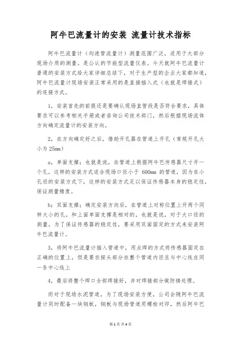
阿牛巴流量计的安装流量计技术指标阿牛巴流量计(均速管流量计)测量范围广泛,适用于大部分现场介质的测量。
是公认的节能型流量仪表。
今天就阿牛巴流量计普通的安装方式给大家详细总结下,对于生产型的企业大家都知道,阿牛巴流量计现场安装正常采用的是直接插入式(也就是焊接式)的连接方式。
1,安装首先的前提还是要确认现场直管段是否符合要求,具体要求可以参考相关手册或者咨询公司技术部门,然后根据现场流体方向确定流量计的安装方向。
2,在方向确定好之后,借助开孔器在管道上开孔(常规开孔大小为25mm)a,单面支撑;也就是说,在管道上根据阿牛巴传感器尺寸开一个孔,这样的安装方式适合现场口径小于600mm的管道,因为在小孔径的安装方式下,这样的安装方式足以保证传感器本身的稳定性,保证测量精度。
b;双面支撑;确定安装方向后,在管道上对称位置上开两个同样大小的孔,和上面单面支撑是相对的,也就是说,对于大口径的测量,为了保证传感器的稳定性,要采用双面固定的方式来安装阿牛巴流量计。
3,将阿牛巴流量计插入管道中,用点焊的方式将传感器固定在正确的位置上,但是要求探头部分在整个管道内径且与中心线在同一条中心线上4,最后将整个焊口全部焊接好,并对焊接部分做防锈处理。
而对于现场水泥管道,为了现场安装方便,公司会随阿牛巴流量计同时配备一块钢板,钢板与现场管道用螺栓对卯,然后阿牛巴流量计和钢板还是采取上述安装方式。
一、指针抖动:1.轻微指针抖动:一般由于介质波动引起。
可采用增加阻尼的方式来克服。
2.中度指针抖动:一般由于介质流动状态造成。
对于气体一般由于介质操作压力不稳造成。
可采用稳压或稳流装置来克服或加大浮子流量计气阻尼。
3.剧烈指针抖动:主要由于介质脉动,气压不稳或用户给出的气体操作状态的压力、温度、流量与浮子流量计实际的状态不符,有较大差异造成浮子流量计过量程。
二、指针停到某一位置不动主要原因是浮子流量计的浮子卡死一般由于金属管转子流量计使用时开启阀门过快,使得浮子飞快向上冲击止动器,造成止动器变形而将浮子卡死。
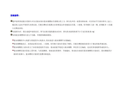
安装指导:
超声波明渠流量计的探头可以直接安装在量水堰槽水位观测点的上方。
探头发声的一面要对准水面。
可以用水平尺放在探头上盖上,通过校上盖水平使探头对准水面。
巴歇尔槽水位观测点在距喉道2/3收缩段长位置;三角堰、矩形堰在上游一侧,距堰板3~4倍最大过堰水深处。
安装探头时,要注意超声波的盲区。
即当出现可能的最高水位时,探头距水面的距离不小于盲区距离(0.4m)
安装量水堰槽须注意几个问题,否则影响测流精度:
量水堰槽的中心线要与渠道的中心线重合,使水流进入量水堰槽不出现偏流。
量水堰槽通水后,水的流态要自由流。
三角堰、矩形堰下游水位要低于堰坎;巴歇尔槽的淹没度要小于规定的临界淹没度。
量水堰槽的上游应有大于5倍渠道宽的平直段,使水流能平稳进入量水堰槽。
即没有左右偏流,也没有渠道坡降形成的冲力。
量水堰槽安装在渠道上要牢固。
与渠道侧壁、渠底连结要紧密,不能漏水。
使水流全部流经量水堰槽的计量部位。
量水堰板的计量部位是堰口;量水槽的计量部位是槽内喉道段。
FLOWMETER INSTRUCTIONSGENERAL INFORMATION Inspect instrument for possible visible damage resulting from shipping. Notify UPS or other carrier as well as the distributor where the flowmeter was purchased of any claims. Flowmeters always must be installed in a vertical position, any significant deviation from vertical will affect the readings. Valves should be closed before installation and opened gradually after all connections are carefully inspected. A leak test is highly recommended especially w hen hazardous fluids are involved. CAUTION: Excessive tightening of valves may damage the orifice. It is important that all lines to be connected to the flowmeter are purged of any dust or other residual contamination prior to installing the meter. All P and S style flowmeters are equipped with a filter in the inlet port. In some applications an additional filter should be installed at the inlet of the flowmeter. STICKING FLOATS Before installing open the valve of the flowmeter and check to make sure that the float or floats are moving freely in the flowtube. This is best done by slowly tilting the flowmeter from horizontal to vertical while observing if the float is rolling freely. All meters are thoroughly inspected at the factory prior to shipping and are sealed in polyethylene bags to prevent dirt from entering into the flow passages. Certain small bore flowtubes have a clearance between the float and the inside walls of the flowtube of only a few ten thousandths of an inch. In some cases these flowtubes are found to have floats that are sluggish of not moving due to condensation resulting from temperature changes during shipping. It is advisable to blow a dry clean gas through the meter to free float. SAFETY INFORMATION P and S style flowmeters are designed to be operated at pressures not exceeding 200 psig (13.6 bars), or temperatures not exceeding 250 degrees F (121deg.C). T style flowmeters are designed to be operated at pressures not exceeding 100 psig (6.8 bars), or temperatures not exceeding 150 degrees F (65.5deg.C). NOTE: When u sing a T style Teflon flowmeter, at a pressure and/or temperature greater than standard the leak integrity approaches 1x10. Standard conditions are considered to be 14.7 psia (1 bar) and 70 degrees F (21deg.C). All meters are factory tested for leakage prior to shipping. For hazardous fluids the flowmeter must be re-tested at the time of installation in the system, prior to usage. It is also important that a leak integrity test is performed periodically to maintain safe operating conditions. Flowmeters must be protected from breakage due to external conditions such as objects bumping into or hitting the instrument, extreme vibrations, or attack by corrosive materials. It is the responsibility of the customer to acquaint the operator(s) of this flowmeter with all appropriate safety information. VALVE ALIGNMENT The built-in needle valve may be positioned at either the inlet or the outlet of the flowmeter. Valves are factory installed at the inlet of the flowmeter unless otherwise requested. APPLICATION VALVE POSITION Exhaust pressure at Valve at Inlet Atmospheric conditions Exhaust pressure other that Valve at Outlet Atmospheric conditions * Vacuum Valve at Outlet Liquid flow Valve at Inlet or Outlet* When using a flowmeter with exhaust pressure greater than atmospheric conditions the standard calibrations can not be used. A calibration for the operating pressure must be obtained. OPERATING INSTRUCTIONS Close valve (if applicable) before initial use, then pressurize the system. Slowly open the valve until the float is at the desired flow rate. The flow rate is read at the center of the float. FLOWTUBE INSTALLATION OR REMOVAL Remove the Front Shield and Back Plate. Do not remove the side panels from the flowmeter. To remove the flowtube: P style meters: insert a 5/32” hex wrench into the Pressure Nut at the top of the flowmeter. While holding the flowtube between your thumb and forefinger, turn the wrench counter clockwise to release the flowtube. Carefully remove the flowtube as not to damage it. S and T style meters: insert a 3/32” diameter rod in the holes of the Lock Nut at the top of the flowtube. While holding the flowtube between your thumb and forefinger, turn the tool clockwise to release the flowtube. It may be necessary to push t h e Tube Adapter into the upper block to remove the flowtube. To reinstall the flowtube reverse the above procedure. Take care to assure that the flowtube is centered, in the meter, at the top and bottom before tightening. T style meters require additional tightening to insure proper sealing at the flowtube ends. The flowmeter should be tightened again 24 hours after the initial tightening. A leak integrity test is recommended after disassembling any flowmeter. FLOWTUBE CLEANING If necessary, remove the flowtube from the frame as explained above, and clean as follows: Insert a plastic rod that will fit into the flowtube with no obstruction, into the bottom of the flowtube and push the retaining plugs and float out of the flowtube. Use tweezers to handle the float and store the float and the plugs in a lint free container. Before removing note the position of the plugs for reference when reassembling. Using a suitable solvent clean all the parts including the flowtube, dry them by means of a clean stream of air or gas. To reassemble the flowtube use the push rod to first install the lower plug, next insert the float and then the upper plug. Test by slowly tilting the flowtube from horizontal to vertical to assure that the float is moving freely. If the float is free follow the instructions above to reinstall the flowtube in the frame. MAINTENANCE Under normal operating conditions no special maintenance is required. Dirt or contamination may create problems within the flowtube by causing a restriction in the flow passage. Such conditions can be diagnosed by examining the flowtube. The most obvious indication of obstruction is the float being stuck in the flowtube. If the existence of the contamination is determined the condition may be rectified in a number of ways. The easiest being (if possible), to disconnect the inlet and the outlet of the flowmeter and purge the instrument by using a clean and dry stream of gas. The action of the float within the bore of the flowtube very often causes particles to be dislodged through the outlet of the flowmeter.TDV0102SM。
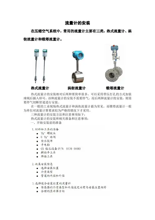
流量计的安装在压缩空气系统中,常用的流量计主要有三类,热式流量计、涡街流量计和锥塔流量计。
热式流量计涡街流量计锥塔流量计热式流量计的安装相对后两种要简单很多,可以采用带压打孔的方式加装球阀后插入即可,该种流量计的安装不需要停气,而后两种流量计的安装,则需要停气切断管道进行安装。
在一般的工业现场热式流量计和涡街流量计最为常见,而锥塔流量计一般为单位对流量计算要求较为严格的情况下才采用。
三种流量计的安装方法和注意事项如下:热式流量计的安装和相关准备和注意事项:一、开始安装前的准备二、选择合适的安装位置1、安装位置为何如此重要?2、合适安装位置的考虑三、安装步骤四、安装后的核查五、该种流量计安装常见的错误六、具体的实际操作请详见知道录像视频(播放文件)涡街流量计的安装和相关注意事项:一、安装要求:二、安装条件:三、安装步骤:四、注意事项:五、实际图片:锥塔流量计的安装和相关注意事项:对于塔形流量计,一次传感器部分是指流量计本体如何与工艺管道连接的工作、尽管流量计有多种结构形式,如:管道式、夹装式、对焊式等。
如果描述不作特殊说明,安装方法是等同的。
由于流量计具有对流体流动状态整流的功能,因此一次传感器部分的安装要求远不孔板等相对宽松的多。
由于流量计是管段式,它与工艺管道的同轴度、垂直度无严格的要求。
1、管道法兰式:是指流量计两端有安装法兰。
与工艺管道两端同规格的安装法兰(也称用户法兰)连接,是比较常用的结构形式,适用的口径(DN50mm~3000mm)。
此种形式适用于节流装置与差压变送器分体安装时选用,一般常用于测量蒸汽流量时使用,在测量其他高温介质时也可以使用。
2、法兰夹装式:用于小口经流量计的安装形式,每台流量计玉工艺管道只需2片法兰。
法兰与工艺管道焊接在一起,再把流量计夹装在两法兰之间。
此中安装方法与涡街流量计(≤300mm)安装方法相同。
3、管道对焊式:是指塔形流量计与工艺管道无法兰连接(流量计本体无法兰),安装时直接把流量计与工艺管道焊接在一起。
管道流量计安装的正确方法一、安装前的准备工作咱得先把要用的工具和材料都准备好。
像什么扳手啦,密封材料啦,可不能到时候安装一半才发现少东西,那就太抓瞎啦。
然后呢,要好好看看流量计的说明书,这就像是它的小自传一样,里面有好多关于它的秘密呢。
比如说它的型号规格,适用的管道尺寸范围,还有一些特殊的安装要求。
可别小看这个说明书,要是不看,就像不看地图就出门旅行,很容易走弯路的。
再就是要检查管道。
管道要是不干净,里面有杂质或者铁锈啥的,就像给流量计准备了一个布满陷阱的家。
所以得把管道清理得干干净净的,最好用专门的清洁工具把里面都擦一擦,这样流量计住进去才舒服。
二、选择合适的安装位置这安装位置可太关键啦。
就像咱们选房子,得找个风水好的地方。
对于流量计来说呢,要尽量安装在管道比较直的部分,要是安装在弯管或者阀门附近,那测量的数据就像调皮的小孩子一样,一点都不准确。
而且啊,安装的地方还得方便咱们平时去查看和维护。
要是把它装在一个特别隐蔽的角落,每次去检查都得费好大的劲儿,那可不行。
还有哦,要避免有强磁场或者震动特别大的地方。
强磁场就像一个小恶魔,会干扰流量计的正常工作。
震动大的话,就像让流量计在蹦床上工作,它能好好干活才怪呢。
三、安装的具体操作把流量计往管道上装的时候,可不能毛毛躁躁的。
要轻轻的,就像对待一个小宝贝一样。
密封一定要做好,如果密封不好,就像房子漏风一样,那测量的液体或者气体就会偷偷跑掉一部分,数据肯定就不对啦。
在连接管道和流量计的时候,螺栓要拧紧,但是也不能使太大的劲,不然把螺栓拧断了或者把流量计的接口弄坏了,那可就麻烦大了。
这就像是给一个小盒子盖盖子,要盖紧,但也不能把盒子压坏了。
四、安装后的检查安装完了可不能就拍拍屁股走人啦。
要检查一下整个安装是不是牢固,有没有松动的地方。
就像盖完房子要检查一下地基稳不稳一样。
然后呢,要给流量计通上电或者通上流体,看看它是不是正常工作。
要是数据显示不正常,那就得像医生看病一样,一点点排查问题出在哪。
流量仪表流量计安装技术要求
流量计安装地点应尽量避开震动源、电场、磁场等,如现场条件无法满足时,应采取管道加固、屏蔽等措施以避免外界对流量计的干扰。
流量计在安装时应注意流量计本体上的流向标示与工艺流体的流向一致。
流量计的入口(上游)与出口(下游)应保留足够长的直管段。
转子流量计要垂直安装,出口(下游)接头在流量计的顶端。
入口(上游)接头在流量计的底端,即最大刻度分度以及测量管的最大部分是在顶部,转子流量计在生产过程中既要拆开进行清扫又不希望停车,则需安装切断阀和旁路阀,旁路管的口径应与主管线一样。
涡轮流量计一般安装在水平管线上,条件受限的情况下可以安装在垂直管道上,但对这种位置必须进行校验。
涡轮流量计的精度和重复性与上游和下游的配管方案有关。
除此之外,涡轮流量计想要获得极高的精度就需要安装整流器,整流器应安装在流量计入口至少10倍管径的地方。
在带法兰的流量仪表安装中,应注意检查管线垫片不突出到流体流束之内而影响流线的形状。
对煤浆等固液混合介质,电磁流量计应考虑垂直安装,流体向上并且在流量计的进口侧有一段直管段。
因固液混合介质在流速比较低的时候,介质在管道中可能出现不满管,或出现固液两相分层现象,这种配置使磨损比较均匀。
更换安装流量计操作规程一、准备工作1.穿戴好劳保用品。
2.准备工具、用具、材料。
校对好的流量计一块,300mm活动扳手2把,F扳手一把,200mm螺丝刀1把,钢丝刷1把,三角刮刀1把,划规1把,300mm钢直尺1把,剪刀1把,10mm石棉板一张,润滑脂(黄油)一袋,棉纱、毛毡2张,放空桶一个,笔一只,纸一张。
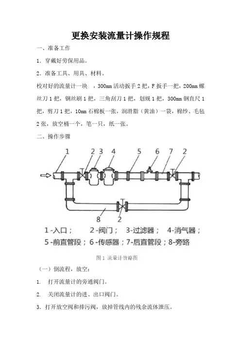
二、操作步骤(一)倒流程,放空:1. 打开流量计的旁通阀门。
2. 关闭流量计的进、出口阀门。
3.打开放空阀和排污阀,放掉管线内的残余流体泄压。
(二)记流量计底数4.把流量计底数记在纸上。
(三)拆卸流量计5.正确使用扳手拆卸螺栓,检查保养并摆放整齐。
6.拆下流量计放在毛毡上。
(四)安装流量计7.清理法兰,量尺寸,剪垫子,抹黄油,安装垫子。
8.按要求摆放流量计。
9.对角紧固螺栓,安装流量计。
(五)倒流程试压10.关放空阀,倒回原来生产流程。
11.依次开流量计的出口阀门、进口阀门,关旁通阀门,试压。
(六)清理现场12.清理现场,收回工具。
三、操作要点详解(一)各种工具的正确使用1.F扳手使用时开口方向正确,防止掉落伤人。
2.按要求使用活动扳手上卸螺栓。
3.要求使用钢直尺,读数准确。
(二)倒流程顺序1.拆卸流量计前:1)打开旁通,2)关流量计进口阀,3)关流量计出口阀。
2.安装好流量计试压前:1)关闭放空阀,2)开流量计出口阀,3)开流量计进口阀,4)关闭旁通阀。
(三)制作法兰垫片1.用钢直尺量出流量计连接法兰密封面的内、外圆直径,计算出半径,如图2(a)所示。
2.在石棉板上确定圆心,用划规分别在石棉板上划出法兰垫片内外圆和长约5cm的操作手柄,如图2(b)所示。
3.用剪刀剪出法兰垫片,并剪出操作手柄,如图2(c)所示。
1-法兰片;2-钢直尺;3-划规;4-石棉垫片;5-弯剪子;6-法兰垫片手柄(四)拆卸流量计1.拆卸流量计两侧法兰紧固螺栓时,先拆法兰下螺栓,再拆上螺栓。
2.用撬杠对称撬动流量计两侧法兰间隙,使流量计主体与两侧法兰活动,移开流量计主体,放在毛毡上。
阿牛巴流量计原理
阿牛巴流量计原理可以简单地解释为:将流量计安装在流体运行的管道中,利用流体的压力,运用某种工作原理来测量流体的流量,然后将流量数据转换成电信号输出,从而可以直观地显示流量大小。
阿牛巴流量计的工作原理可以分为三个步骤:首先,流量计的传感器将流体的压力信号转换为电信号;其次,通过放大器放大电信号;最后,将放大后的电信号发送到显示器,从而实现流量显示。
由于阿牛巴流量计在测量流量时不会改变流体特性和状态,因此在测量过程中不会发生污染。
此外,在测量流量时,可以根据流体的不同性质和特性来选择不同类型的流量计,从而更好地满足流量测量的要求。
阿牛巴流量计的应用非常广泛,可以用于各种流量测量的场合,如工业自动化、热能利用、水处理系统、化工科学、汽车行业等。
它可以用于测量各种流体的流量,如液体、气体、蒸汽等,并且能够实现高精确度的流量测量。
总之,阿牛巴流量计的原理是把流体的压力信号转换为电信号,然后由放大器放大,最后发送到显示器,从而实现流量显示,具有污染小、精度高、应用广泛等特点,是目前应用较为广泛的流量测量方法之一。
阿牛巴流量计技术标准一、引言阿牛巴流量计是一种用于测量液体或气体流体流量的设备,它能够准确地测量流体的流速和流量,对于工业生产、环保监测等领域有着重要的应用价值。
为了确保各种流量计在使用过程中能够达到准确、稳定的测量效果,我们制定了以下阿牛巴流量计技术标准,以指导生产、安装和维护过程中的操作。
二、类型与原理阿牛巴流量计根据测量原理的不同,可以分为多种类型,包括电磁流量计、涡轮流量计、超声波流量计等。
每种类型的流量计都有其独特的测量原理和适用范围,应根据具体的使用场景选择合适的类型。
电磁流量计通过测量导电液体在磁场中的运动情况来计算流体流速和流量,适用于各种导电液体的测量。
涡轮流量计基于旋转轴的转速来计算流体流速和流量,适用于干净的液体和气体。
超声波流量计则利用超声波在流体中的传播速度差来计算流速和流量,适用于各种液体和气体。
在选择具体类型的流量计时,需要根据测量介质的性质、流速范围、精度要求等因素进行综合考虑。
三、性能要求1. 测量范围:阿牛巴流量计应能够满足不同流速、流量范围的测量需求,能够适应各种工况下的测量要求。
2. 精度:流量计应具备较高的测量精度,能够在不同流量下保持稳定的测量准确度。
3. 反应速度:流量计的响应速度应快,能够及时准确地反映流体流速和流量的变化。
4. 稳定性:流量计在长时间使用过程中应具备良好的稳定性,不受外部环境干扰影响测量效果。
5. 温度、压力适应性:流量计应能够适应不同温度、压力下的工作环境,具有良好的适应性和稳定性。
6. 耐腐蚀性:流量计应具备一定的耐腐蚀性能,能够适用于不同介质的测量。
7. 可靠性:流量计应具备良好的可靠性和稳定性,能够在长时间使用过程中保持良好的测量性能。
四、安装与调试1. 安装要求:流量计的安装位置应考虑介质流动的稳定性和均匀性,避免受到外界扰动;同时应避开热源、振动源等可能影响测量的因素。
2. 导电介质测量:对于电磁流量计而言,测量介质必须具备一定的导电性能,且不应含有气泡、泥沙等杂质,以保证测量的准确性。
常用流量计的正确安装方式流量计指示被测流量和(或)在选定的时间间隔内流体总量的仪表,也是测量液体、气体流量必不可少的仪表,大家平时想必也都见过许多不同类型的流量计。
正确的安装方式对流量计来说十分重要。
下面通过本文跟随流程君来了解一下八类常用流量计的安装要点。
流量计的历史:流量测量的发展可追溯到古代的水利工程和城市供水系统。
古罗马凯撒时代已采用孔板测量居民的饮用水水量。
公元前1000年左右古埃及用堰法测量尼罗河的流量。
我国著名的都江堰水利工程应用宝瓶口的水位观测水量大小等等。
17世纪托里拆利奠定差压式流量计的理论基础,这是流量测量的里程碑。
自那以后,18、19世纪流量测量的许多类型仪表的雏形开始形成,如堰、示踪法、皮托管、文丘里管、容积、涡轮及靶式流量计等。
20世纪由于过程工业、能量计量、城市公用事业对流量测量的需求急剧增长,才促使仪表迅速发展,微电子技术和计算机技术的飞跃发展极大地推动仪表更新换代,新型流量计如雨后春笋般涌现出来。
至今,据称已有上百种流量计投向市场,现场使用中许多棘手的难题可望获得解决。
我国开展近代流量测量技术的工作比较晚,早期所需的流量仪表均从国外进口。
一、电磁流量计的正确安装方式电磁流量计的测量原理不依赖流量的特性,如果管路内有一定的湍流与漩涡产生在非测量区内则与测量无关。
安装要点A、安装地点不能有大的振动源,并应采取加固措施来稳定仪表附近的管道;B、不能安装在大型变压器、电动机、机泵等产生较大磁场的设备附近,以免受到电磁场的干扰;C、传感器与管道连接时应保证满管运行,最好垂直安装;D、变送器外壳接地与就近接地网连接即可;屏蔽电缆(分体式)按说明书连接,信号电缆(至系统)进行屏蔽层系统处单端接地;测量传感器与管道连接的短路环需要接地,接地电阻应小于10欧姆,不能与电气接地共用;E、流量计传感器上游也应该有一定的直管段,一般在5D~10D。
安装详解如下:如果在测量区内有稳态的涡流则会影响测量的稳定性和测量的精度,这时可以增加前后直管段的长度、采用一个流量稳定器或减少测量点的截面以稳定流速分布。
⼏种巴类流量计的安装使⽤注意事项什么是巴类流量计?巴流量计适⽤于⽓体、液体和蒸汽的⾼精度流量测量。
威⼒巴是⼀种差压式、速率平均式流量传感器,通过传感器在流体中所产⽣的差压进⾏流量测量。
威⼒巴反映流体真实的流速,其精度达到± 1.0%,重复性达± 0.1%。
在差压式流量计中,巴类(均速管)是近年⽐较流⾏的产品,进⼝阿⽜巴(阿纽巴),德尔塔巴,威⼒巴和依特巴,因为它们有着压损低,安装⽅便,重复性好等特点,特别是在⼤管径测量⽅⾯,有很⼤的优越性。
1、安装毕托巴流量计前,管道要清扫。
被测介质不洁净时,要加过滤器。
否则涡轮、轴承易被卡住,测不出流量来。
2、拆装流量计时,对磁感应部分不能碰撞。
3、投运前先进⾏仪表系数的设定。
仔细检查,确定仪表接线⽆误,接地良好,⽅可送电。
4、安装毕托巴流量计时,前后管道法兰要⽔平,否则管道应⼒对流量计影响很⼤。
5、流量计本体最好选区⽤316不锈钢材料以防腐,如是防爆区还必须是防爆结果。
6、轴承⼀般有炭化钨,聚四氟⼄烯,碳⽯墨三种规格:碳化钨的精度最⾼,它作为⼯业控制的标准件;聚四氟⼄烯,碳⽯墨能防腐,⼀般在化⼯场所优先考虑。
轴承的寿命流速的平⽅成正反⽐,故流速最好的在最⼤流速的1/3速度⽐较好。
7、感应探头是检测转动体的运动并把它转化为脉冲数字电信号,它电磁线圈电压输出值接近正弦曲线,脉冲信号的频率范围随测量的流量⼤⼩成线性变化,典型的范围为10:1,25:1 和100:1三种规格。
电磁线圈的电阻⼀般⼩于2000Ω,⼤于该值可能损坏。
毕托巴流量计的安装说明 1、变送器的电源线采⽤⾦属屏蔽线,接地要良好可靠。
电源为直流24V,650Ω阻抗。
2、变送器应⽔平安装,避免垂直安装,并保证其前后有适应的直管段,⼀般前10D,后5D。
3、保证流体的流动⽅向与仪表外壳的箭头⽅向⼀致,不得装反。
4、被测介质对涡轮不能有腐蚀,特别是轴承处,否则应采取措施。
阿纽巴流量计简明安装指南适用: 485 阿纽巴法兰式(Flanged Annubar) 液体和气体应用,步骤 1 : 确定正确的485阿纽巴 (485Annubar)的安装方向和直管段要求水平管线 垂直管线直管段要求安装法兰对面支持件安装法兰步骤 2 :在管线上钻孔注意: 管线上必须钻孔, 如果采用乙炔气体或其它烧蚀方法开孔, 安装后的最大流量误差可达10% !!!1.将管线泄压, 排出积存液体2.选择你将钻孔的位置针对垂直管线可在周线方向任意位置开孔.针对水平管线, 开孔的位置依据阿钮巴 (Annubar)测量流体的应用.∙测量液体 : 在管线的底部开孔∙测量气体 : 在管线的顶部开孔∙测量蒸汽 : 在管线的底部开孔3.依据上表, 确定开孔的尺寸.4.开孔后,去孔内毛刺.5.如果也需要安装对向支撑, 于第一个开孔的正对方向钻第二个孔,然后去孔内毛刺.步骤 3 : 将焊接连接件焊接到管线上1.将阿纽巴与工厂提供的焊接连接件组装好,然后插入钻好的孔内.2.以阿纽巴的安装头上平面(或变送器---如果是一体化仪表)对线定位, 使之平行地面.3.点焊, 将焊接连接固定到管线上,然后将阿纽巴传感器拆下.4.焊接之前,为防止焊渣飞溅损坏连接件螺纹, 用工厂提供的厚铝箔包裹螺纹部分,或拧上一个保护螺帽. 完成焊接. .步骤4 : 插入安装阿纽巴流量计1.安装连接件完全冷却后, 安装连接体.2.在密封压紧环和预焊接锁紧环之间装入第一个密封环(盘根);注意不要损坏密封环.3.将密封环压入连接体内部至预焊接锁紧环. 重复以上步骤将其余二个密封环装入,调整密封环开口的位置,使每个开口的位置交错成180度.4.调整阿纽巴方向,将阿纽巴头部上的箭头标记指向管线的流体方向,用手将 Pak-Lok压紧螺母与连接体拧紧. 以手拧不动为止.5.用扳手锁紧 Pak-Lok螺母,扳手每次旋转 90 度,直至压紧螺母共转动360度.Pak-Lok压紧螺母拧紧的程度可以避免泄漏即可. 不要过分用力旋紧压紧螺母, 否则会损坏安装部件.6.安装传感器过程中压紧螺母的旋转最多不可超过 1-1/4 圈(圈=360度).end.Welcome To Download !!!欢迎您的下载,资料仅供参考!。
iPFs-0XX iPFs-1XXTABLe OF cONTeNTs General information General Information, Features, Specifications .................................................................................................Page 1installationPiping, Positioning the Meter, Immersion, Depth Setting ................................................................................Page 2IPFS-0 Installation, IPFS-1 Installation .............................................................................................................Page 3Dimension C, Pipe Wall Thickness ....................................................................................................................Page 4Flow Rate ............................................................................................................................................................Page 4Straight Pipe Recommendations ......................................................................................................................Page 5Full Pipe Recommendations ..............................................................................................................................Page 6connectionCalibration ..........................................................................................................................................................Page 7Operation & repairTheory of Operation, Flow Range, Rotor Replacement ....................................................................................Page 8repair & PartsSignal, Parts Explosion, Parts List ....................................................................................................................Page 9TroubleshootingProblem, Probable Cause, To Try.......................................................................................................................Back TABLes AND DiAGrAMsFeatures ..............................................................................................................................................................Page 1Specifications Table ...........................................................................................................................................Page 1Piping ..................................................................................................................................................................Page 2Positioning the Meter .........................................................................................................................................Page 2Depth Setting .....................................................................................................................................................Page 2Meter Installation ...............................................................................................................................................Page 3Table 1 (Dimension 'C') ......................................................................................................................................Page 4Table 2 (Pipe Wall Thickness) ............................................................................................................................Page 4Straight Pipe Recommendations ......................................................................................................................Page 5Full Pipe Recommendations ..............................................................................................................................Page 6Connection Diagram ..........................................................................................................................................Page 7K factor ................................................................................................................................................................Page 7Rotor Replacement ............................................................................................................................................Page 8Parts Explosion ...................................................................................................................................................Page 9Parts List .............................................................................................................................................................Page 9Troubleshooting: Problem, Probable Cause, To Try ..........................................................................................BackPage 1GeNerAL iNFOrMATiONFeATUresAdapter fitting with 2” NPT threadsFull-port 2” ball valve for sensor removal 2” Adapterremoves to mount hot-tap machine 3/4” diameter tubing for low insertion force iPFs-1XXRotor18 Foot CableModular electronics (optional) • rate/total/pulse/4-20 mA • blind 4-20 transmitter • pulse dividerCompression nutAdapter fittingRotor housingRemovable jewel bearings for exceptional low flow performance iPFs-0XXsPeciFicATiONs*GeNerAL iNFOrMATiONThe IPFS Series are adjustable depth insertion paddlewheels that come in brass or 316 stainless models to fit 3” to 40” pipe. Installation fittings are standard 1-1/2" or 2” NPT. Fittings such as saddles and weldolets may be purchased either locally or from Dwyer Instruments Inc.Ruby bearings and a non-drag Hall-effect sensor give these meters the widest flow range of any of the paddlewheel types. A sensor detects the passage of miniature magnets in the six rotor blades. The resulting square-wave signal can be sent for hundreds of feet over unshielded cable without a transmitter and connected directly to many PLC’s and other controls without any additional electronics.If desired, a modular system of electronics can be installed directly on the flow sensor or mounted remotely. The Series RTI provides digital rate and total display, as well as programmable pulse output; the Series RTI also provides a 4 to 20 mA analog output. The Series BAT is a blind analog transmitter. Program-mable pulse for pump pacing is available with the Series PWD.The “hot-tap” models IPFS-1 can be installed or serviced without shutting down the line by means of a 2” full-port isolation valve that comes with a nipple for installation on the pipe fitting. In most circumstances, no special tool is required.s-size L-size3” to 12” (50 - 300mm) 12” to 40” (300 - 1000mm)Hall Effect sensor, 12 Vdc current sinking pulse Cast aluminum Brass or 316 SS PVDFNickel-bound tungsten carbide (zirconia ceramic optional)Ruby jeweli PFs-0 i PFs-1 None Bronze (316SS optional) 1.5” NPT 2” NPT0.3 - 30 feet/sec (0.1 - 9 meter/sec)+/- 1.5% of full scale 200˚ F (93˚ C)200 psi (14 bar)0.44 x pressure in pipe 5-24 Vdc, 1.5 mA#22 AWG 3-con, 18’ (6m); 2,000’ (650m) maximum cable runPipe size sensorMaterials Housing sensor Body rotor shaft Bearingsisolation ValveFitting size Flow range AccuracyMaximum Temperature Maximum Pressure insertion Force Power cable*Specifications subject to change.immersion. The IPFS Series standard sensors are not designed for continuous underwater operation. If this is a possibility, as in a flooded vault, a unit modified for immersion should be specified (Option -IMM)Depth setting. It is important for accuracy that the sensor be inserted to the correct depth into the pipe.1. In Table 1 (on page 4), find Dimension C for your sensor modeland pipe size.2. Subtract wall thickness of your pipe (Table 2 on page 4) to find Dimension D.3. Measuring from the outside of the pipe to the joint in the housing, as shown in the diagram, adjust the sensor to Dimension D and hand tighten compression nut.4. Align the conduit housing with the centerline of the pipe, as shown below. Be sure the arrow on the housing points in the direction of flow.5. Check Dimension D one more time.6. Tighten the compression nut fully.recOrD YOUr seTTiNGsOnce you have the meter set up and operational, it is im-portant to record your meter setttings and save them for future reference.K-FactorInsertion Depth (Dim. D)iNsTALLATiONPage 2POsiTiONiNG THe MeTerFair (unacceptable if air is present)Fair (unacceptable if fluid contains sediment)BestPiping. For best results, the IPFS sensor should be installed with at least ten diameters of straight pipe upstream and five downstream. Certain extreme situations such as partially-opened valves are particularly difficult and may require fifteen diameters upstream. (See Straight Pipe Recommendations.)Horizontal is the preferred installation orientation, since it improves low-flow performance slightly and avoids problems with trapped air. Bottom, top, and vertical pipe installations are all acceptable if required by the piping layout. (See Full Pipe Recommendations.)These flow sensors are not recommended for installation downstream of the boiler feedwater pump where installation fault may expose the meter to boiler pressure and temperature. Maximum recom-mended temperature is 200˚ F.iPFs-0XX iNsTALLATiONFitting installation. IPFS-0XX sensors come with a 1-1/2” male NPT pipe thread adapter fitting. Any fitting that provides the matching NPT female thread may be used. Installation procedure compensates for fitting height differences. Cut a minimum 1-3/4” hole in the pipe. If possible, measure the wall thickness and write it down for use in depth setting. Then install the threaded fitting (saddle, weldolet, etc.) on the pipe.Meter i nstallation. Loosen the compression nut so that the adapter slides freely. Pull the meter fully upward and finger-tighten the compres -sion nut. Using a thread sealant, install the adapter in the pipe fitting. Do not overtighten. Now loosen the compression nut, lower the meter to the appropriate depth setting (see diagram and instructions, preceding page). caution: Do not allow the meter to fall into the pipe uncontrolled, as this may damag the meter . Be sure flow is in the direction of the arrow on the housing. Tighten compression nut fully.iPFs-1XX iNsTALLATiON‘Hot tap’ meters are designed to be installed and serviced without depressurizing the pipe.Fitting i nstallation. The hot tap sensors have a 2” NPT thread for compatibility with the 2” isolation valve. Any fitting that provides matching NPT female thread may be used. The installation procedure compensates for differences in fitting height.If initial installation is performed on an unpressurized pipe, cut a minimum 1-3/4” hole in the pipe. If possible, measure the wall thickness and write it down for use in depth setting. Then install the threaded fitting (saddle, weldolet, etc.) on the pipe.If it is necessary to do the initial installation under pressure, any standard hot tap drilling machine with 2” NPT adapter, such as a Transmate or a Mueller, can be used. Ordinarily, it is not necessary to use an installation tool, since the small-diameter tube can be controlled by hand but not for higher pressures.Meter installation. Remove the sensor unit from the valve assembly. Using a thread sealant, install the valve assembly on the pipe fitting. If the initial installation is a pressure (“hot”) tap, remove the 1-1/2” x 2” adapter bushing at the back of the valve. Thread the tapping machine on, open the valve, and tap using a minimum of 1-3/4” or maximum 1-7/8” cutter. After retracting the machine and closing the valve, reinstall the flow sensor. When the sensor is secure, open the valve and adjust depth setting (see diagram and instructions, preceding page). Be sure flow is in the direction of the arrow on the housing. Tighten locking collar and compression nut fully.Compression nutAdapter fittingwithstandard NPT threadsFull-port 2” ball valve allows sensorremoval Standard 2” NPT threadsiPFs-1XX sensorremovaliNsTALLATiON Page 3FLOWstrain reliefPage 4iNsTALLATiON Page 5iNsTALLATiONsTrAiGHT PiPe recOMMeNDATiONs (X = diameter)5X10X5X10X 5X20X 5X20X30X50Xreduced PipeTwo elbows in Plane Two elbows, Out Of Planeexpanded Pipeswirling FlowPropeller MeterPartially OpenButterfly Valvespiral FlowiPFsiPFsiPFsiPFsiPFsiPFsiNsTALLATiON caution:These flow sensors arenotrecommended forinstallation down -stream of the boiler feedwater pump where installation fault may expose theflow sensor to boiler pressure and temperature. Maximum recommendedtemperature is 200°F.FULL PiPe recOMMeNDATiONs recOMMeNDeDNOT recOMMeNDeDrecOMMeNDeDNOT recOMMeNDeD Allows air pockets to form at sensorEnsures full pipePost-valve cavitation can create air pocketKeeps pipe full at sensorAir can be trapped Allows air to bleed offrecOMMeNDeDNOT recOMMeNDeDPage 7Page 6cONNecTiON cONNecTiONSensors are supplied with 18 ft. of cable. For sensors with no additional electronics, see diagram for color coding of connections. For sensors with on-board electronics, see the manual accompanying the electronic module.calibration (“K-Factor”). In order to properly process pulses fromthe flow sensor, a number must be entered into the control to which the sensor is connected. This number, called the K-factor, is the number of pulses the sensor puts out per unitoffluid passing through the pipe. It is normally provided for Seametricssensors in pulses per gallon, and is given on the chart “K-factors for Various Pipe Sizes.” These numbers are based on extensive testing, which has shown close agreement between different IPsensors in the same installation. Typically, most K-factor error can be attributed to installation variables, such as depth settingand fitting configuration.It is occasionally possible to field calibrate a sensor by catching the fluid in a measured container and comparing with the number of pulses recorded. (To record individual pulses, set the K-factor on the control to 1.00.) This is especially desirable if the instal-lation has less than the recommended length of straight pipe upstream of the sensor.rePAir & PArTssignalThe flow sensor has only one moving part, the rotor. If this is turning properly and there is no signal, the Hall-effect sensor is not operating properly. To check the signal, apply 12 Vdc regu-lated* power to the red (+) and black (-) leads. Set a multimeter to voltage reading. Put the positive multimeter lead on the red wire and the negative lead on the white wire. Slowly turn the rotor. Voltage reading should swing between +12 Volts and 0 Volts as the rotor turns. If it does not, the Hall effect sensor is not working properly. Checking for continuity is not a useful test of these sensors.*NOTe: An unregulated power supply can exceed max voltage of micro powered sensor (gray cable) and damage sensor..IPFS-0XX Parts1Upper housing assembly 2Gasket 3Lower housing 4Housing screw (4 req'd)5Plug, steel 6Plug, plastic 7Strain relief8Pickup, Standard (for RTI)9Tube10Compression nut 11Compression ferrule 12Adapter fitting13Rotor housing O-ring (EPDM)14Rotor housing 15Jewel bearings (2 req)16Rotor with shaft 17Rotor repair kit(includes of #15 & #16)Page 8Parts explosionIPFS-1XX (HOT-TAP) Parts (not shown)Adapter fitting Ball valve assembly Collar, locking Hex nipple, 2"Page 9rotor replacement. Rotors are easily field-replaced. Shaft and rotor are a single unit, and are not replaced separately. If replacement is due only to normal shaft wear, bearing re-placement is probably not necessary. If the rotor has been damaged by impact, the bearings should also be replaced. Rotor and bearings can be ordered as a kit. Follow these steps:1. Unscrew the threaded bearing housings to expose the shaft ends. If bearings are being replaced, back them completely out.2. Remove the rotor. Put the new rotor in its place.3. Thread in one bearing housing part way, then the other. Take care to start the end of the shaft into the bearing hole before tightening further.4. Screw in bearing housings until they bottom. Note : Do not use excessive force.5. Check for free spin. Blowing lightly on the rotor should result in it spinning rapidly and coasting to a smooth stop.rePAircaution! Never attempt to remove a flowsensor when there is pressure in the pipe unless it is specifically designed for hot tap installation and removal. Loosen thecompression nut slowly to release any trapped pres-sure. If fluid sprays out when removing the sensor, stop turning and depressurize the pipe. Failure to do so could result in the sensor being thrown from the pipe, resulting in damage or serious injury.OPerATiONTheory. In principle, an insertion flow sensor measures the velocity of flow at one point in the pipe, and flow rate and total can be inferred from this one point. Accuracy is decreased by any factor which makes the flow at the measured point unrepresentative of the entire flow stream. This includes distorted flow patterns caused by upstream fittings too close to the sensor. The worst offenders are fittings that increase the flow on one side of the pipe, such as partially-opened gate or butterfly valves. Fluid moving in a pipe does not all flow at the same velocity. Toward the center of the pipe, fluid moves faster than at the wall, and the relationship be -tween the two changes as overall flow rate increases. This change in the “velocity profile” can result in non-linearity, which means that the K-factor that is correct for one flow rate may be incorrect for another. The recommended depth settings have been carefully chosen to minimize this source of error, and should be followed carefully, especially in the smaller pipe sizes.Flow range. These sensors are designed to operate at flow velocities of 0.3 to 30 feet per second. If erratic readings are encountered at low flows, check the chart to see if flow is below minimum for the pipe size. The standard shaft and bearings should have a long life at continuous high flow.OPerATiON & rePAir Refer to "Terms and Conditions of Sale" in our catalog or on our website. Contact customer service to receive a Returns Goods Authorization number before shipping your product back for repair. Be sure to include a brief description of the problem plus any relevant applciation notes.WArrANTY/reTUrNPL-OM-65200389-0905129/5/2012Dwyer Instruments, Inc. • 102 Indiana Highway 212 • Michigan City, IN 46360 • USA(P ) 219.879.8868 • (F ) 219.872.9057 • 1.800.872.9141 • TrOUBLesHOOTiNG。
阿纽巴流量计简明安装指南
适用: 485 阿纽巴法兰式(Flanged Annubar) 液体和气体应用,
步骤 1 : 确定正确的485阿纽巴 (485Annubar)的安装方向和直管段要求水平管线垂直管线
直管段要求
安装法
兰
对面支持件
安装法兰
步骤 2 :在管线上钻孔
注意: 管线上必须钻孔, 如果采用乙炔气体或其它烧蚀方法开孔, 安装后的最大流量误差可达10% !!!
1.将管线泄压, 排出积存液体
2.选择你将钻孔的位置
针对垂直管线可在周线方向任意位置开孔.
针对水平管线, 开孔的位置依据阿钮巴 (Annubar)测量流体的应用.
•测量液体 : 在管线的底部开孔
•测量气体 : 在管线的顶部开孔
•测量蒸汽 : 在管线的底部开孔
3.依据上表, 确定开孔的尺寸.
4.开孔后,去孔内毛刺.
5.如果也需要安装对向支撑, 于第一个开孔的正对方向钻第二个孔,然后去孔内毛刺.
步骤 3 : 将焊接连接件焊接到管线上
1.将阿纽巴与工厂提供的焊接连接件组装好,然后插入钻好的孔内.
2.以阿纽巴的安装头上平面(或变送器---如果是一体化仪表)对线定位, 使之平行地面.
3.点焊, 将焊接连接固定到管线上,然后将阿纽巴传感器拆下.
4.焊接之前,为防止焊渣飞溅损坏连接件螺纹, 用工厂提供的厚铝箔包裹螺纹部分,
或拧上一个保护螺帽. 完成焊接. .
步骤4 : 插入安装阿纽巴流量计
1.安装连接件完全冷却后, 安装连接体.
2.在密封压紧环和预焊接锁紧环之间装入第一个密封环(盘根);注意不要损坏密封环.
3.将密封环压入连接体内部至预焊接锁紧环. 重复以上步骤将其余二个密封环装入,
调整密封环开口的位置,使每个开口的位置交错成180度.
4.调整阿纽巴方向,将阿纽巴头部上的箭头标记指向管线的流体方向,用手将 Pak-Lok
压紧螺母与连接体拧紧. 以手拧不动为止.
5.用扳手锁紧 Pak-Lok螺母,扳手每次旋转 90 度,直至压紧螺母共转动360度. Pak-
Lok压紧螺母拧紧的程度可以避免泄漏即可. 不要过分用力旋紧压紧螺母, 否则会损坏安装部件.
6.安装传感器过程中压紧螺母的旋转最多不可超过 1-1/4 圈(圈=360度).
end.。