CR0119 FPGA_STARTUPx Powerup Delay Unit
- 格式:pdf
- 大小:64.19 KB
- 文档页数:3

西安邮电大学FPGA课程设计报告题目:电风扇的自动定时开关控制器院系:电子工程学院专业班级:微电子0901学生姓名:李小斌导师姓名:黄海生起止时间: 2012-6-18 至 2012-6-29 2012 年6 月29 日目录1.任务 (2)2.目的 (2)3.使用环境 (2)4.FPGA课程设计详细内容 (2)4.1 技术规范 (2)4.1.1 总体描述 (2)4.1.2 结构框图.............................................................. 错误!未定义书签。
4.1.3 引脚描述.............................................................. 错误!未定义书签。
4.1.3 应用范围 (5)4.2 设计方案 (5)4.2.1 顶层方案设计 (5)4.2.2 顶层模块程序 (7)4.3 功能验证方案及源程序 (7)4.3.1按键输入控制模块方案设计及源程序 (7)4.3.2控制模块方案设计及源程序 (8)4.3.3LCD驱动模块方案设计及源程序 (11)4.4 电路设计及功能仿真报告............................................ 错误!未定义书签。
4.5 综合及布局布线报告和引脚分布报告 (21)4.6 硬件测试结果报告 (21)5.课程设计的心得体会 (22)6.参考资料 (22)1、任务题目:电风扇的自动定时开关控制器及FPGA功能验证设计;主要任务:运用FPGA(SPARTAN 3E)设计一个风扇定时开关控制器,能实现手动和自动模式之间的切换。
设计后能对设计进行功能上和时序上的验证和仿真测试。
2、目的(1)熟悉FPGA开发的环境和FPGA的结构,了解FPGA开发的流程,熟悉进行verilog设计时各种报告的格式;(2)能够更熟练地使用verilog设计FPGA;(3)增加把知识用于实践的实践能力。

彩星CT2119总线进入方法。
彩星CT2119总线进入方法:拆开用户遥控器,在IC9脚接一连线,再在IC14脚接二极管的另一端即二极管D704负极(不是IC14脚)接一连线,这样,用户的遥控器就改装成了工厂总线调整遥控器。
要进入总线,内需将二根线短接一下,在屏幕上右上角即可看到"D"字符,即已进入总线方式。
遥控芯片型号:9028-023,以上方法同样适用于厦华,海尔,乐华等采用东芝芯片的电视机,其解码芯片为TB1238。
乐华R25T88进入维修状态求助乐华R25T88如何进入维修状态。
CPU型号是LC863320A-5M06。
按用户遥控器左下角暗藏键即可进入维修状态不用拆开遥控也可进入维修状态,步骤是:按住面板“音量减”至音量为00后不放,再按一下遥控器的“召回”,松开“音量减”键;同时按下面板“音量减”键与摇控器的“召回”,再按一下遥控器的“召回”,同时按下面板“音量减”键与摇控器的“召回”即可进入亮暗平衡调节,再按一下遥控器的“召回”,同时按下面板“音量减”键与摇控器的“召回”即可进入维修状态,遥控关机后即可退出。
彩星CT2168进入总线方法机型:ct2168cpu:tmp87cm38n-tc48小信号处理:tb1238请各位大虾帮忙她的总线进入方法谢彩星2168彩电ic总线资料《转帖》一、进入方法:打开遥控器,在上方中间有一暗藏键,按一次为“s”壮态。
再按一次为“d”壮态。
节目键调整项目,音量键调整数据,遥控关机退出。
二、数据见下表:(下列数据是在我销售的多台新机上得到的,现整理出来供同行参考)项目工厂调试项目数据内容说明(说明内容是我补上的,可能会有误,仅供参考)01 rcut 85 红暗平衡02 gcut 7e 绿暗平衡03 bcut 99 兰暗平衡04 gdrv 40 绿亮平衡05 bdrv 43 兰亮平衡06 cntx 30 对比度最大值07 brtc 28 亮度最大值08 colc 30 n制色度中间值09 tntc 30 色度中间值10 colp 33 p制亮度中间值11 cols 2e s制色度中间值12 scnt 0e 副对比度13 cnct 1d 副对比度中间值14 cntn 06 副对比度最小值15 brtx 2f 副亮度最大值16 brtn 18 副亮度最小值17 colx 25 副色度最大值18 coln 00 副色度最小值19 tntx 42 副色调最大值20 tntn 35 副色调最小值21 st3 09 tv-3.58清晰度22 sv3 09 av-3.58清晰度23 st4 09 tv-4.43清晰度24 sv4 09 av-4.43清晰度25 shdx 16 清晰50hz帧中心度最大值26 shdn 05 清晰度最小值27 txcx 3a28 rgcn 2e29 vmo 2c vct数据030 vm1 2e vct数据131 hpos 08 50hz行中心32 vp50 04 50hz帧中心33 hit 18 50hz帧副度34 hps 05 50/60hz帧中心35 vp60 01 60hz帧中心36 hits 0037 viln 0c 50hz帧线性38 vsc 0a 帧s校正39 vlis(c) ff 50/60hz帧线性40 dpc 00 机行校正41 dpcs 0042 key 0043 keys 0044 wid 00 50hz行幅45 wids 0046 vcp 00 帧补偿47 cnr 00 顶角修正48 hcp 00 行补偿49 sby 08 secamb-y50 sry 08 secamr-y51 ragc 18 高放agc52 aft 23 中放aco53 hatc 00 afc增益54 v25 50 音量25%55 v50 56 音量50%56 brts 06 副亮度57 vm2 30 cts-763a58 modo 00 模式数据059 mod1 92 模式数据160 mod2 0a 模式数据261 self 00 自检62 self aco 80 自检aco63 self agc 69 自检agc64 self brtc 75 自检亮度中间值65 self cntc 23 自检对比度中间值66 self tntc 00 自检色度中间值67 self coc 2068 logo 0369 lang 0170 iffreq 04LA7688832A进工厂菜单方法按MENU键→返回键→睡眠键就进去了嘉华21W3彩电 I2C 总线进入方法!嘉华21W3 I2C 总线进入方法有谁愿赐教多谢!!!!。

UG0881User Guide PolarFire SoC FPGA Booting And ConfigurationMicrosemi HeadquartersOne Enterprise, Aliso Viejo,CA 92656 USAWithin the USA: +1 (800) 713-4113 Outside the USA: +1 (949) 380-6100 Sales: +1 (949) 380-6136Fax: +1 (949) 215-4996Email: *************************** ©2020 Microsemi, a wholly owned subsidiary of Microchip Technology Inc. All rights reserved. Microsemi and the Microsemi logo are registered trademarks of Microsemi Corporation. All other trademarks and service marks are the property of their respective owners. Microsemi makes no warranty, representation, or guarantee regarding the information contained herein or the suitability of its products and services for any particular purpose, nor does Microsemi assume any liability whatsoever arising out of the application or use of any product or circuit. The products sold hereunder and any other products sold by Microsemi have been subject to limited testing and should not be used in conjunction with mission-critical equipment or applications. Any performance specifications are believed to be reliable but are not verified, and Buyer must conduct and complete all performance and other testing of the products, alone and together with, or installed in, any end-products. Buyer shall not rely on any data and performance specifications or parameters provided by Microsemi. It is the Buyer’s responsibility to independently determine suitability of any products and to test and verify the same. The information provided by Microsemi hereunder is provided “as is, where is” and with all faults, and the entire risk associated with such information is entirely with the Buyer. Microsemi does not grant, explicitly or implicitly, to any party any patent rights, licenses, or any other IP rights, whether with regard to such information itself or anything described by such information. Information provided in this document is proprietary to Microsemi, and Microsemi reserves the right to make any changes to the information in this document or to any products and services at any time without notice.About MicrosemiMicrosemi, a wholly owned subsidiary of Microchip T echnology Inc. (Nasdaq: MCHP), offers a comprehensive portfolio of semiconductor and system solutions for aerospace & defense, communications, data center and industrial markets. Products include high-performance and radiation-hardened analog mixed-signal integrated circuits, FPGAs, SoCs and ASICs; power management products; timing and synchronization devices and precise time solutions, setting the world's standard for time; voice processing devices; RF solutions; discrete components; enterprise storage and communication solutions, security technologies and scalable anti-tamper products; Ethernet solutions; Power-over-Ethernet ICs andmidspans; as well as custom design capabilities and services. Learn more at .Contents1Booting And Configuration . . . . . . . . . . . . . . . . . . . . . . . . . . . . . . . . . . . . . . . . . . . . .11.1Boot-up Sequence . . . . . . . . . . . . . . . . . . . . . . . . . . . . . . . . . . . . . . . . . . . . . . . . . . . . . . . . . . . . . . . . . . 11.1.1MSS Pre-Boot . . . . . . . . . . . . . . . . . . . . . . . . . . . . . . . . . . . . . . . . . . . . . . . . . . . . . . . . . . . . . . 21.1.2MSS User Boot . . . . . . . . . . . . . . . . . . . . . . . . . . . . . . . . . . . . . . . . . . . . . . . . . . . . . . . . . . . . . 81.2Different Sources of Booting . . . . . . . . . . . . . . . . . . . . . . . . . . . . . . . . . . . . . . . . . . . . . . . . . . . . . . . . . . 91.3Boot Configuration . . . . . . . . . . . . . . . . . . . . . . . . . . . . . . . . . . . . . . . . . . . . . . . . . . . . . . . . . . . . . . . . . . 9 2Acronyms . . . . . . . . . . . . . . . . . . . . . . . . . . . . . . . . . . . . . . . . . . . . . . . . . . . . . . . . .10 3Revision History . . . . . . . . . . . . . . . . . . . . . . . . . . . . . . . . . . . . . . . . . . . . . . . . . . . .113.1Revision 2.0 . . . . . . . . . . . . . . . . . . . . . . . . . . . . . . . . . . . . . . . . . . . . . . . . . . . . . . . . . . . . . . . . . . . . . . 113.2Revision 1.0 . . . . . . . . . . . . . . . . . . . . . . . . . . . . . . . . . . . . . . . . . . . . . . . . . . . . . . . . . . . . . . . . . . . . . . 11FiguresFigure 1Boot-up Sequence . . . . . . . . . . . . . . . . . . . . . . . . . . . . . . . . . . . . . . . . . . . . . . . . . . . . . . . . . . . . . . 1 Figure 2MSS Pre-boot Flow . . . . . . . . . . . . . . . . . . . . . . . . . . . . . . . . . . . . . . . . . . . . . . . . . . . . . . . . . . . . . . 2 Figure 3Idle Boot Flow . . . . . . . . . . . . . . . . . . . . . . . . . . . . . . . . . . . . . . . . . . . . . . . . . . . . . . . . . . . . . . . . . . 3 Figure 4Non-secure Boot Flow . . . . . . . . . . . . . . . . . . . . . . . . . . . . . . . . . . . . . . . . . . . . . . . . . . . . . . . . . . . 4 Figure 5User Secure Boot Flow . . . . . . . . . . . . . . . . . . . . . . . . . . . . . . . . . . . . . . . . . . . . . . . . . . . . . . . . . . . 5 Figure 6Factory Secure Boot Flow . . . . . . . . . . . . . . . . . . . . . . . . . . . . . . . . . . . . . . . . . . . . . . . . . . . . . . . . 7 Figure 7SoftConsole Project . . . . . . . . . . . . . . . . . . . . . . . . . . . . . . . . . . . . . . . . . . . . . . . . . . . . . . . . . . . . . 8 Figure 8Typical Linux Boot Process Flow . . . . . . . . . . . . . . . . . . . . . . . . . . . . . . . . . . . . . . . . . . . . . . . . . . . 8TablesTable 1MSS Core Complex Boot Modes . . . . . . . . . . . . . . . . . . . . . . . . . . . . . . . . . . . . . . . . . . . . . . . . . . . 2 Table 2U_MSS_BOOTCFG Usage in Non-Secure Boot Mode 1 . . . . . . . . . . . . . . . . . . . . . . . . . . . . . . . . . 3 Table 3U_MSS_BOOTCFG Usage in User Secure Boot . . . . . . . . . . . . . . . . . . . . . . . . . . . . . . . . . . . . . . . 4 Table 4Secure Boot Image Certificate (SBIC) . . . . . . . . . . . . . . . . . . . . . . . . . . . . . . . . . . . . . . . . . . . . . . . 6 Table 5U_MSS_BOOTCFG Usage in Factory Boot Loader Mode . . . . . . . . . . . . . . . . . . . . . . . . . . . . . . . . 6 Table 6List of Acronyms . . . . . . . . . . . . . . . . . . . . . . . . . . . . . . . . . . . . . . . . . . . . . . . . . . . . . . . . . . . . . . . 101Booting And ConfigurationPolarFire SoC FPGAs use advanced power-up circuitry to ensure reliable power on at power-up andreset. At power-up and reset, PolarFire SoC FPGA boot-up sequence follows Power-on reset (POR),Device boot, Design initialization, Microcontroller Subsystem (MSS) pre-boot, and MSS user boot. Thisdocument describes MSS pre-boot and MSS User Boot. For information about POR, Device Boot andDesign initialization, see UG0890: PolarFire SoC FPGA Power-Up and Resets User Guide.For more information about MSS features, see UG0880: PolarFire SoC MSS User Guide.1.1Boot-up SequenceThe boot-up sequence starts when the PolarFire SoC FPGA is powered-up or reset. It ends when theprocessor is ready to execute an application program. This booting sequence runs through severalstages before it begins the execution of programs.A set of operations are performed during the Boot-up process that includes power-on reset of thehardware, peripheral initialization, memory initialization, and loading the user-defined application fromnon-volatile memory to the volatile memory for execution.The following figure shows different phases of the Boot-up sequence.Figure 1 • Boot-up Sequence1.1.1MSS Pre-BootUpon successful completion of Design Initialization, MSS Pre-boot starts its execution. The MSS isreleased from a reset after completion of all normal startup procedures. The system controller manages the programming, initialization, and configuration of the devices. MSS Pre-boot does not occur if the programmed device is configured for system controller suspend mode.The MSS pre-boot phase of initialization is coordinated by system controller firmware, although it may make use of the E51 in the MSS Core Complex to perform certain parts of the pre-boot sequence.The following events occur during the MSS pre-boot stage:•Power-up of the MSS embedded Non-Volatile Memory (eNVM)•Initialization of the redundancy repair associated with the MSS Core Complex L2 cache •Authentication of User boot code (if User Secure boot option is enabled) •Handover operational MSS to User Boot codeThe MSS Core Complex can be booted in one of four modes. The following table lists the MSS pre-boot options, which can be configured and programmed into the sNVM. The boot mode is defined by the user parameter U_MSS_BOOTMODE[1:0]. Additional boot configuration data is mode-dependent and is defined by the user parameter U_MSS_BOOTCFG (see Table 3, page 4 and Table 5, page 6).The boot option is selected as part of the Libero design flow. Changing the mode can only be achieved through the generation of a new FPGA programming file.Figure 2 • MSS Pre-boot FlowTable 1 • MSS Core Complex Boot ModesU_MSS_BOOTMODE[1:0]ModeDescription 0Idle bootMSS Core Complex boots from boot ROM if MSS is not configured 1Non-secure bootMSS Core Complex boots directly from address defined by the U_MSS_BOOTADDR 2User secure bootMSS Core Complex boots from sNVM 3Factory secure boot MSS Core Complex boots using the factory secure boot protocol1.1.1.1Idle BootIf the MSS is not configured (for example, blank device), then the MSS Core Complex executes a bootROM program which holds all the processors in an infinite loop until a debugger connects to the target.The boot vector registers maintains their value until the device is reset or a new boot mode configurationis programmed. For configured devices, this mode can be implemented using theU_MSS_BOOTMODE=0 boot option in the Libero configurator.Note:In this mode, U_MSS_BOOTCFG is not used.The following figure shows the Idle boot flow.Figure 3 • Idle Boot FlowIn this mode, the MSS Core Complex executes from a specified eNVM address without authentication. Itprovides the fastest boot option, but there is no authentication of the code image. The address can bespecified by setting U_MSS_BOOTADDR in the Libero Configurator. This mode can also be used to bootfrom any FPGA Fabric memory resource through FIC. This mode is implemented using theU_MSS_BOOTMODE=1 boot option.The MSS Core Complex is released from reset with boot vectors defined by U_MSS_BOOTCFG (aslisted in the following table).Table 2 • U_MSS_BOOTCFG Usage in Non-Secure Boot Mode 1Offset(bytes)Size (bytes)Name Description04BOOTVEC0Boot vector for E5144BOOTVEC1Boot vector for U54084BOOTVEC2Boot vector for U541164BOOTVEC3Boot vector for U542204BOOTVEC4Boot vector for U543Figure 4 • Non-secure Boot Flow1.1.1.3User Secure BootThis mode allows user to implement their own custom secure boot and the user secure boot code isplaced in the sNVM. The sNVM is a 56 KB non-volatile memory that can be protected by the built-inPhysically Unclonable Function (PUF). This boot method is considered secured because sNVM pagesmarked as ROM are immutable. On power up, the system controller copies the user secure boot codefrom sNVM to Data Tightly Integrated Memory (DTIM) of the E51 Monitor core. E51 starts executing theuser secure boot code.If the size of the user secure boot code is more than the size of the DTIM then user needs to split theboot code into two stages. The sNVM may contain the next stage of the user boot sequence, which mayperform authentication of the next boot stage using the user authentication/decryption algorithm.If authenticated or encrypted pages are used then the same USK key (that is,U_MSS_BOOT_SNVM_USK) must be used for all authenticated/encrypted pages.If authentication fails, the MSS Core Complex can be placed in reset and the BOOT_FAIL tamper flagcan be raised. This mode is implemented using the U_MSS_BOOTMODE=2 boot option.Table 3 • U_MSS_BOOTCFG Usage in User Secure BootOffset (bytes)Size (bytes)Name Description01U_MSS_BOOT_SNVM_PAGE Start page in SNVM13RESERVED For alignment412U_MSS_BOOT_SNVM_USK For authenticated/encrypted pagesFigure 5 • User Secure Boot Flow1.1.1.4Factory Secure BootIn this mode, the system controller reads the Secure Boot Image Certificate (SBIC) from eNVM andvalidates the SBIC. On successful validation, System Controller copies the factory secure boot code fromits private, secure memory area and loads it into the DTIM of the E51 Monitor core. The default secureboot performs a signature check on the eNVM image using SBIC which is stored in eNVM. If no errorsare reported, reset is released to the MSS Core Complex. If errors are reported, the MSS Core Complexis placed in reset and the BOOT_FAIL tamper flag is raised. Then, the system controller activates atamper flag which asserts a signal to the FPGA fabric for user action. This mode is implemented usingthe U_MSS_BOOTMODE=3 boot option.The SBIC contains the address, size, hash, and Elliptic Curve Digital Signature Algorithm (ECDSA) signature of the protected binary blob. ECDSA offers a variant of the Digital Signature Algorithm which uses elliptic curve cryptography. It also contains the reset vector for each Hardware thread/core/processor core (Hart) in the system. DSNIf the DSN field is non-zero, it is compared against the device's own serial number. If the comparison fails, then the boot_fail tamper flag is set and authentication is aborted.VERSIONIf SBIC revocation is enabled by U_MSS_REVOCATION_ENABLE, the SBIC is rejected unless the value of VERSION is greater than or equal to the revocation threshold. SBIC REVOCATION OPTIONIf SBIC revocation is enabled by U_MSS_REVOCATION_ENABLE and OPTIONS[0] is ‘1’, all the SBIC versions less than VERSION are revoked upon complete authentication of the SBIC. The revocation threshold remains at the new value until it increments again by a future SBIC with OPTIONS[0] = ‘1’ and a higher VERSION field. The revocation threshold may only be incremented using this mechanism and can only be reset by a bit-stream.When the revocation threshold is updated dynamically, the threshold is stored using the redundant storage scheme used for passcodes such that a power failure during device boot does not cause a subsequent device boot to fail. If the update of revocation threshold fails, it is guaranteed that the threshold value is either the new value or the previous one.Table 4 • Secure Boot Image Certificate (SBIC)Offset Size (bytes)Value Description04IMAGEADDR Address of UBL in MSS memory map44IMAGELEN Size of UBL in bytes 84BOOTVEC 0Boot vector in UBL for E51124BOOTVEC 1Boot vector in UBL for U540164BOOTVEC 2Boot vector in UBL for U541204BOOTVEC 3Boot vector in UBL for U542244BOOTVEC 4Boot vector in UBL for U543281OPTIONS[7:0]SBIC options283RESERVED 328VERSION SBIC/Image version 4016DSN Optional DSN binding 5648HUBL image SHA-384 hash 104104CODESIG DER-encoded ECDSA signature Total 208BytesTable 5 • U_MSS_BOOTCFG Usage in Factory Boot Loader Mode Offset (bytes)Size (bytes)NameDescription04U_MSS_SBIC_ADDRAddress of SBIC in MSS address space44U_MSS_REVOCATION_ENABLE Enable SBIC revocation if non-zeroThe following figure shows the factory secure boot flow. Figure 6 • Factory Secure Boot Flow1.1.2MSS User BootMSS user boot takes place when the control is given from System Controller to MSS Core Complex.Upon successful MSS pre-boot, system controller releases the reset to the MSS Core Complex. MSScan be booted up in one of the following ways:•Bare Metal Application•Linux Application•AMP Application1.1.2.1Bare Metal ApplicationThe bare metal applications for the PolarFire SoC can be developed using SoftConsole tool. This toolprovides the output files in the form of .hex which can be used in the Libero flow to include into theprogramming bitstream file. The same tool can be used to debug the Bare Metal applications using JTAGinterface.Th following figure shows the SoftConsole Bare Metal application which has five harts (Cores) includingE51 Monitor core.Figure 7 • SoftConsole ProjectThis section describes the boot sequence for Linux running on all U54 cores.A typical boot process consists of three stages. The first stage boot loader (FSBL) gets executed fromthe on-chip Boot flash (eNVM). The FSBL loads the second stage boot loader (SSBL) from a boot deviceto external RAM or Cache. The boot device can be eNVM or embedded memory microcontroller (eMMC)or external SPI Flash. The SSBL loads the Linux operating system from boot device to external RAM. Inthe third stage, Linux is executed from the external RAM.The following figure shows the Linux Boot Process flow.Figure 8 • Typical Linux Boot Process FlowDetails of FSBL, Device tree, Linux, and YOCTO build, how to build and configure Linux will be providedin the future release of this document.1.1.2.3AMP ApplicationDetailed description of Libero MSS Configurator and how to debug multi-processor applications usingSoftConsole will be provided in the future release of this document.1.2Different Sources of BootingTo be updated in future versions of this document.1.3Boot ConfigurationTo be updated in future versions of this document.Acronyms2AcronymsThe following acronyms are used in this document.Table 1 • List of AcronymsAcronym ExpandedAMP Asymmetric Multi-processingDTIM Data Tightly Integrated Memory (also called as SRAM)ECDSA Elliptic Curve Digital Signature AlgorithmeNVM embedded Non-Volatile MemoryFSBL First Stage Boot LoaderHart Hardware thread/core/processor coreMSS Microprocessor SubsystemPOR Power on ResetPUF Physically Unclonable FunctionROM Read-only MemorySCB System Controller BridgesNVM Secure Non-volatile MemoryRevision History3Revision HistoryThe revision history describes the changes that were implemented in the document. The changes arelisted by revision, starting with the current publication.3.1Revision 2.0The following is a summary of the changes made in this revision.•Information about Factory Secure Boot was updated.•Information about Bare Metal Application was updated.3.2Revision 1.0The first publication of this document.。
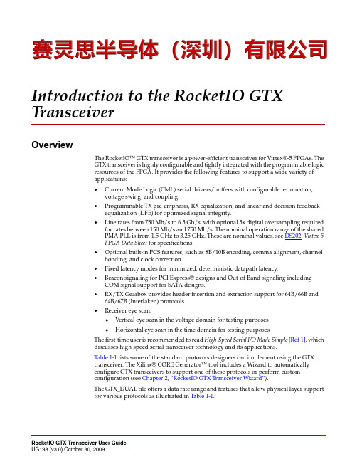
Introduction to the RocketIO GTX TransceiverOverviewThe RocketIO™ GTX transceiver is a power-efficient transceiver for Virtex®-5 FPGAs. TheGTX transceiver is highly configurable and tightly integrated with the programmable logicresources of the FPGA. It provides the following features to support a wide variety ofapplications:•Current Mode Logic (CML) serial drivers/buffers with configurable termination,voltage swing, and coupling.•Programmable TX pre-emphasis, RX equalization, and linear and decision feedbackequalization (DFE) for optimized signal integrity.•Line rates from 750Mb/s to 6.5Gb/s, with optional 5x digital oversampling requiredfor rates between 150Mb/s and 750Mb/s. The nominal operation range of the sharedPMA PLL is from 1.5GHz to 3.25GHz. These are nominal values, see DS202: Virtex-5FPGA Data Sheet for specifications.•Optional built-in PCS features, such as 8B/10B encoding, comma alignment, channelbonding, and clock correction.•Fixed latency modes for minimized, deterministic datapath latency.•Beacon signaling for PCI Express® designs and Out-of-Band signaling includingCOM signal support for SATA designs.•RX/TX Gearbox provides header insertion and extraction support for 64B/66B and64B/67B (Interlaken) protocols.•Receiver eye scan:♦Vertical eye scan in the voltage domain for testing purposes♦Horizontal eye scan in the time domain for testing purposesThe first-time user is recommended to read High-Speed Serial I/O Made Simple[Ref1], whichdiscusses high-speed serial transceiver technology and its applications.Table1-1 lists some of the standard protocols designers can implement using the GTXtransceiver. The Xilinx® CORE Generator™ tool includes a Wizard to automaticallyconfigure GTX transceivers to support one of these protocols or perform customconfiguration (see Chapter2, “RocketIO GTX Transceiver Wizard”).The GTX_DUAL tile offers a data rate range and features that allow physical layer supportfor various protocols as illustrated in Table1-1.Chapter 6:GTX Transmitter (TX)TX GearboxOverviewSome high-speed data rate protocols use 64B/66B encoding to reduce the overhead of8B/10B encoding while retaining the benefits of an encoding scheme. The TX Gearboxprovides support for 64B/66B and 64B/67B header and payload combining. TheInterlaken interface protocol specification uses the 64B/67B encoding scheme. Refer to theInterlaken specification for further information. The Interlaken specification can bedownloaded . The TX Gearbox only supports 2-byte and 4-byte interfaces. A 1-byteinterface is not supported.Scrambling of the data is done in the FPGA logic. The RocketIO™ GTX Transceiver Wizardhas example code for the scrambler.Ports and AttributesTable6-6 defines the TX Gearbox ports.Table 6-6:TX Gearbox PortsPort Direction Clock Domain DescriptionTXGEARBOXREADY0 TXGEARBOXREADY1Out TXUSRCLK2Output indicating how data is applied to TX Gearbox.0: No data can be applied1: Data must be appliedUse with attributes GEARBOX_ENCDEC_0 andGEARBOX_ENCDEC_1.TXHEADER0[2:0] TXHEADER1[2:0]In TXUSRCLK2Input for header bits.Bit[2]: Indicates data inverted for 64B/67B encodingBit[1:0]: The encoding for these bits is:01: Data header10: Control headerTXSEQUENCE0[6:0] TXSEQUENCE1[6:0]In TXUSRCLK2Input from 7-bit/6-bit counter in FPGA logic to the TXGearbox. Time to data for 64B/67B and 64B/66B.TXSTARTSEQ0 TXSTARTSEQ1In TXUSRCLK2Input to TX Gearbox indicating the first character in the datasequence for 64B/67B and 64B/66B encoding.TX GearboxInternal Sequence Counter Operating ModeAs shown in Figure6-15, the internal sequence counter operating mode uses the TXSTARTSEQ input and the TXGEARBOXREADY output in addition to the TXDATA data inputs and the TXHEADER header inputs. In this use model, the TXSEQUENCE inputs are not used. The use model is similar to the previous use model except that the TXGEARBOXREADY output is not used.Chapter 6:GTX Transmitter (TX)Table 6-10 defines the TX buffering and phase-alignment attributes.DescriptionUsing the TX BufferTo use the TX buffer to resolve phase differences between the domains, TX_BUFFER_USEmust be set to TRUE. The buffer should be reset whenever TXBUFSTATUS indicates anoverflow or an underflow. The buffer can be reset using GTXRESET (see “Reset,” page 101)Table 6-10:TX Buffering and Phase-Alignment Attributes Attribute Type DescriptionOVERSAMPLE_MODE Boolean This shared attribute activates the built-in 5x digital oversampling circuits inboth GTX_DUAL transceivers. Oversampling is supported between 1/10th ofthe lower border of the shared PMA PLL operating range and 4/10th of theupper border of the shared PMA PLL operating range. For data rates that needa PLL clock without oversampling that is below one-half of the lower borderof the shared PMA PLL, oversampling is mandatory to ensure that the sharedPMA PLL operates in its frequency range.TRUE: Built-in 5x digital oversampling enabled for both GTX transceiverson the tileFALSE: Digital oversampling disabledSee “Oversampling,” page 185 for more details about 5x digital oversampling.PLL_TXDIVSEL_OUT_0PLL_TXDIVSEL_OUT_1Integer Divides the PLL clock to produce a high-speed TX clock. Because both edges of the clock are used, the divided clock must run at one-half the desired TX line rate. Available divider settings are 1, 2, and 4. Each GTX transceiver has a separate PLL_TXDIVSEL_OUT. See “Parallel In to Serial Out,” page 149.PMA_TX_CFG_0PMA_TX_CFG_120-bit Hex TX channel specific settings. The default value is 20'h80082.TX_BUFFER_USE_0TX_BUFFER_USE_1Boolean This attribute must be set to TRUE when the TX buffer is used.TRUE: Use the TX buffer.FALSE: Bypass the TX buffer. The phase-alignment circuit must be usedwhen TX_BUFFER_USE is FALSE.(1)TX_XCLK_SEL0TX_XCLK_SEL1String Selects the clock used to drive the clock domain in the PCS following the TXbuffer. When using the TX buffer, this attribute is set to TXOUT .The attribute must be set as follows:TXOUT: Use when TX_BUFFER_USE = TRUETXUSR: Use when TX_BUFFER_USE = FALSE (1)TXRX_INVERT0TXRX_INVERT13-bit BinaryControls inverters that optimize the clock paths within the GTX transceiverfor different modes of operation. When using the TX buffer, this attribute mustbe set to 3'b011.The attribute must be set as follows:011: Use when TX_BUFFER_USE =TRUE111: Use when TX_BUFFER_USE =FALSE (1)Notes:1.Bypassing the TX buffer is an advanced feature and is not recommended for normal operation. TX buffer bypass operation can be guaranteed only under certain system-level conditions and data rates.TX Buffering, Phase Alignment, and TX Skew Reductionor TXRESET (see “FPGA TX Interface,” page 120). Assertion of GTXRESET triggers a sequence that resets the entire GTX_DUAL tile.Using the TX Phase-Alignment Circuit to Minimize TX SkewTo use the phase-alignment circuit to force the XCLK phase of multiple lanes to match the common TXUSRCLK phase, follow these steps.Initial conditions when TX_BUFFER_USE is TRUE:♦Set TX_BUFFER_USE_0 and TX_BUFFER_USE_1 to TRUE.♦Set TXRX_INVERT0 and TXRX_INVERT1 to 011.♦Set TX_XCLK_SEL0 and TX_XCLK_SEL1 to TXOUT.♦Set PMA_TX_CFG0 and PMA_TX_CFG1 to 20'h80082.1.Set TX_XCLK_SEL0 and TX_XCLK_SEL1 to TXUSR .2.Wait for all clocks to stabilize, then drive TXENPMAPHASEALIGN High.Keep TXENPMAPHASEALIGN High unless the phase-alignment procedure must be repeated. Driving TXENPMAPHASEALIGN Low causes phase alignment to be lost.3.Wait 32 TXUSRCLK2 clock cycles, and then drive TXPMASETPHASE High.4.Wait the number of required TXUSRCLK2 clock cycles as specified in Table 6-11, andthen drive TXPMASETPHASE Low. The phase of the PMACLK is now aligned with TXUSRCLK.5.Set TX_XCLK_SEL0 and TX_XCLK_SEL1 back to TXOUT.6.Assert and deassert TXRESET synchronously to TXUSRCLK. In this use mode,TXRESET must be deasserted simultaneously to all GTX Transceivers on which the deskew operation is being performed.The phase-alignment procedure must be redone if any of the following conditions occur:•GTXRESET is asserted •PLLPOWERDOWN is deasserted •The clocking source changedFigure 6-20 shows the TX phase-alignment procedure. TXENPMAPHASEALIGN(0/1) and TXPMASETPHASE(0/1) are independent for each GTX transceiver. Thisimplementation is different from the GTP_DUAL tile where TXENPHASEALIGN and TXPMASETPHASE are shared tile pins. The procedure is always applied to each GTX transceiver’s TXENPMAPHASEALIGN(0/1) signal on the tile. TXOUTCLK cannot be the source for TXUSRCLK when the TX phase-alignment circuit is used. See “FPGA TX Interface,” page 120 for details.Table 6-11:Number of Required TXUSRCLK2 Clock Cycles PLL_DIVSEL_OUT_0PLL_DIVSEL_OUT_1TXUSRCLK2 Wait Cycles18,192216,384432,767。
一、LAB内部资源Cyclone III 每个LAB包括16个LE ,每个LAB 还包括LAB control signals、LE carry chains、Register chains、Local interconnect,需要对LAB control signals 有所了解。
每个LAB 的LAB control signals 包括Two Clocks、Two clock enables、Two asynchronous clears、One synchronous clear、one synchronous load,这些信号都是LAB-wide 作用的。
LAB-wide: 比如某个LE的register 使用的时钟是clk1,那么这个clk1 的作用域是整个LAB,此LAB 内任何一个register都连接了此clk1,或者说clk1走的是LAB内的时钟网络,注意,虽然作用域是整个LAB,但是任意某个LE 可以选择不用此时钟。
这就像,家里的水龙头,整栋楼使用的是同一个供水管道(作用域:整栋楼),但是对于各家各户,提供给你们家的只是一个水龙头(接口),你可以选择打开或者不用。
对于Cyclone III 每个LAB 有Two clocks ,这就是说这个楼有两个供水管道,每户人家可以选择打开水龙头A 或者水龙头B ,或者不用水。
但是,想打开水龙头C ,对不起,这栋楼只有两个供水管道(假设每个管道只提供给各户一个接口)。
有了上边的概念,一切就简单了。
Two clocks :两个时钟域的不同LEs,可以位于同一个LAB模块内,但是三个时钟域的不同LEs,绝对不同位于同一个LAB中,编译时,布局布线时,编译器会自动把这些LEs分配到不同的LAB内,如果通过Chip Planner ECO 改动不同时钟域(三个以上)的LEs 到同一个LAB 编译时会报错;One synchronous clear :同一个LAB 只有一个同步复位线,不同同步复位的LEs 不能位于一个LAB 内!其它LAB内控制信号亦如此!二、谈一谈复位的问题1、在assignment -setting -Device and Pins -General 中Enable device-wide reset(DEV_CLRn) ,打勾,使能全局清零管脚,不打勾,这个脚就是普通IO 脚,这个脚只能chip-wide 寄存器清零,不能置 1 ,一般不用此脚当复位脚!因为复位后有些初值不希望是0 ,而且这个复位脚只能对寄存器清0 ,对组合逻辑无效。
WUHAN WINNINGCHINA MICROSYSTEM TECHNOLOGIES CO., LTD编号:单芯片方案介绍(内部资料请勿外传)武汉盛华微系统技术股份有限公司WUHAN WINNINGCHINA MICROSYSTEM TECHNOLOGIES CO.LTD(内部资料禁止外传)更改履历表目录1、1x9数字光模块简介 (3)2、常规解决方案 (3)3、单芯片解决方案 (5)4、常规方案和单芯片方案比较 (6)5、单芯片方案的优势 (7)1、1x9数字光模块简介1X9封装的光模块产品最早产生于1999年,是固定的光模块产品,通常直接固化(焊接)在通讯设备的电路板上,作为固定的光模块使用,有时候也叫9针或9PIN光模块。
顾名思义,这种光纤模块有九个PIN角,是早期光模块的最常见的一种封装形式,也是市场需求量非常大的一种类型,主要用在光纤收发器,PDH光端机,光纤交换机,单多模转换器以及一些工业控制领域。
简单的说,1x9光模块就是以光波为载波,已光纤为传输媒介的通信设备,使用光源将电信号变成光信号,输入于光纤传输,使用光探测器把来自光纤的光信号还原成电信号,经放大、整形、再生恢复到原来的电信号。
功能原理如下图所示:图1:光模块功能原理框图2、常规解决方案1x9封装光收发一体模块由光电子器件、功能电路和光接口等组成,包括发射和接收两部分。
常规的解决方案如下:发射部分是:输入一定码率的电信号经内部的驱动芯片(LDD)处理后驱动半导体激光器(LD)或发光二极管(LED)发射出相应速率的调制光信号。
需要采用独立的驱动芯片(LDD)及激光器共同实现发射部分的功能,LDD常用MAXIM和MindSspeed厂家,同时需要配备发光检测电路、光功率控制电路、温度补偿电路等。
也有部分型号的芯片集成了这些功能,如MAX3738等。
使用用背光二极管将激光二极管的光输出转换为相应的光电流,经APC环路反馈来控制激光二析管LD的偏置电流,从而维持光输出功率恒定。
正点原子fpga例程-回复「正点原子FPGA例程」,一步一步解读正点原子是一家专注于FPGA(现场可编程门阵列)开发板及相关技术的公司。
他们提供了一系列例程,让用户能够快速上手并学习使用FPGA。
本文将以「正点原子FPGA例程」为主题,一步一步地解读这些例程。
一、介绍FPGA是一种基于可编程硬件逻辑的芯片,可以根据用户的需求重新配置其内部电路。
正点原子开发的FPGA例程旨在帮助用户了解和掌握FPGA编程的基本概念和技能。
每个例程都包含了详细的说明和可运行的代码,以及对应的硬件开发板。
二、例程列表1. LedBlink:这个例程演示了如何使用FPGA控制开发板上的LED灯进行闪烁。
它介绍了FPGA编程的基本语法和流程,并提供了一个简单的示例代码。
通过跟随这个例程,用户能够快速上手并理解FPGA的基本原理。
2. ButtonInterrupt:在这个例程中,用户将学习如何使用中断处理器来实现按键的响应。
当按下开发板上的按钮时,FPGA将发出中断信号,并执行对应的处理程序。
这个例程展示了如何将硬件和软件结合起来,实现一些简单的交互功能。
3. SevenSegmentDisplay:开发板上的七段数码管是一种常见的输出设备。
这个例程展示了如何使用FPGA控制七段数码管显示数字。
它介绍了数码管的基本原理,以及如何将数字转换为对应的信号控制。
4. VGAOutput:这个例程演示了如何使用FPGA进行VGA图像输出。
用户可以学习到如何生成VGA信号,并将图像数据传输到开发板上的显示器。
这个例程需要一些高级的FPGA编程技巧,但对于有一定经验的用户来说,是一个很好的学习资源。
5. UARTCommunication:这个例程涉及到FPGA的串行通信功能。
用户将学习如何使用FPGA与其他设备进行通信,例如PC或其他开发板。
它介绍了UART协议的基本原理,以及如何在FPGA中实现相应的功能。
三、学习路径正点原子的FPGA例程按照难度和知识点分为不同的学习路径,用户可以根据自己的需求和水平选择合适的路径。
FPGA_STARTUPx Powerup Delay UnitSummaryCore ReferenceCR0119 (v2.0) March 17, 2008This document provides detailed reference information with respect to the powerupdelay unit peripheral device.The FPGA_STARTUPx Powerup Delay Unit is used to provide a delay of specified length, after the physical FPGA device has completed its powerup initialization sequence. This would enable, for example, a microcontroller within a design to be heldwithin the reset state for a specific number of system clock cycles (after FPGA initialization) before entering the normal 'running' state. The design running within the FPGA device would therefore be started explicitly in the reset state.Available DevicesThe following three versions of the unit are available:• FPGA_STARTUP8 – Delay unit with a specified 8-bit delay• FPGA_STARTUP16 – Delay unit with a specified 16-bit delay• FPGA_STARTUP32 – Delay unit with a specified 32-bit delayAll devices in the FPGA_STARTUPx family can be found in the FPGA Peripherals integrated library (FPGAPeripherals.IntLib ), located in the \Library\Fpga folder of the installation.Functional DescriptionSymbolFigure 1. FPGA_STARTUPx SymbolsFPGA_STARTUPx Powerup Delay UnitPin DescriptionTable 1. FPGA_STARTUPx Pin description NameType Polarity/ Bus sizeDescription CLKI Rise External clock signal DELAY I 811632The value assigned to this input determines the length of the delay generated, interms of the number of cycles of the external clock signal wired to CLK. INIT O Level This signal remains High until the end of the specified delay, after which it goesLow and stays Low until the FPGA device is reinitialized.Placing an FPGA_STARTUPx Device in a DesignThe FPGA_STARTUPx family of devices provide a simple method of delaying the operation of a block of logic within a design. This is achieved by holding the design (or part thereof) in the reset state for a specified length of time, after the physical FPGA device has completed its initialization sequence. Figure 2 shows an example of how a Powerup Delay Unit is wired into a design.Figure 2. Using an FPGA_STARTUPx device to hold a design in the reset state for a specified time .In the example circuit above, the Powerup Delay Unit used is the FPGA_STARTUP8. The output of the device has been ORed with the signal from the Test/Reset button on the NanoBoard and wired into the RST inputs of the various blocks within the design. In this example, the two sub-sheets involve TSK165B_D and TSK51A_D microcontrollers respectively.After the physical FPGA device has been programmed with the design it will commence its initialization sequence. Once this has completed, both microcontrollers and the LCD Controller are held in the reset state for a duration specified by the DELAY input of the Powerup Delay Unit.The DELAY bus in this case has been wired to a VCC bus power port. All eight bits are therefore set and the specified delay is 256. The design is therefore held in reset state for 256 cycles of the CLK signal, which in the example of Figure 2 is the NanoBoard clock.After the 256 cycles have completed, the INIT output will go Low. Providing the Test/Reset button on the NanoBoard is not held down, the design will enter normal running operational mode.1 8 = FPGA_STARTUP8; 16 = FPGA_STARTUP16; 32 = FPGA_STARTUP32.FPGA_STARTUPx Powerup Delay UnitUsing Bus Constants to Determine the DelayAny value for delay can be entered, up to the maximum supported for each device. Specification of a length for the delay that is not the maximum can be most easily achieved through the use of Bus Constants.The constant value is specified in the net label for the bus and can be either decimal, binary or hexadecimal. Considering an FPGA_STARTUP16 device and a required delay of 342, the following entries for the bus net label could be used to define the constant:•Decimal: DELAY[15..0] <= 342•Binary: DELAY[15..0] <= b101010110•Hexadecimal: DELAY[15..0] <= $156Figure 3 illustrates the use of a bus constant to define the value for the DELAY input to an FPGA_STARTUP16 device.Figure 3. Specifying the value for DELAY using a bus constant.Revision HistoryDate Version No.Revision30-Jan-2004 1.0 New product release26-May-2005 1.1 Updated for Altium Designer SP412-Dec-2005 1.2 Path references updated for Altium Designer 617-Mar-2008 2.0 Updated for Altium Designer Summer 08Software, hardware, documentation and related materials:Copyright © 2008 Altium Limited.All rights reserved. You are permitted to print this document provided that (1) the use of such is for personal use only and will not be copied or posted on any network computer or broadcast in any media, and (2) no modifications of the document is made. Unauthorized duplication, in whole or part, of this document by any means, mechanical or electronic, including translation into another language, except for brief excerpts in published reviews, is prohibited without the express written permission of Altium Limited. Unauthorized duplication of this work may also be prohibited by local statute. Violators may be subject to both criminal and civil penalties, including fines and/or imprisonment. Altium, Altium Designer, Board Insight, Design Explorer, DXP, LiveDesign, NanoBoard, NanoTalk, P-CAD, SimCode, Situs, TASKING, and Topological Autorouting and their respective logos are trademarks or registered trademarks of Altium Limited or its subsidiaries. All other registered or unregistered trademarks referenced herein are the property of their respective owners and no trademark rights to the same are claimed.。