静电电压表说明书
- 格式:doc
- 大小:159.08 KB
- 文档页数:6
静电电压表一、概述本产品是阻容等电位屏蔽分压式高压测量装置。
主要用于脉冲高压,雷电高压,工频高压的测量。
是代替高压静电电压表的首选。
具有操作简便,显示直观,精度高、体积小、重量轻等特点,适应于发电厂、变电站、高压电器设备制造厂和高电压试验室等部门作为高电压测量之理想装备。
本静电电压表通过仪表线与高压测量端相连,可实现远距离清晰读数,使用安全、方便。
该系列交直流静电电压表输入阻抗高,线性度好,采用特殊的屏蔽技术,减少高压对示值的影响,从而实现高稳定度,高线性度。
采用进口填充材料,使结构更小,重量更轻,可靠性更高,内部局部放电量降到最低。
体积小,重量轻,便于携带,为现场工地的检测工作带来极大的便利。
二、技术参数交流测量方式:真有效值测量精度:AC:1.0% DC: 0.5%绝缘介质:干式介质材料环境条件:温度: -25℃~40℃湿度:<85%分压比:1000:1其他技术参数见附录。
三、使用方法1.将静电电压表接地端安全接地。
2.将高压线接在均压球上方,用接线螺旋栓将高压线拧紧。
3.将仪表底座上的输入端插入静电电压表测量端,测量直流时将钮子开关切换到“DC”档,测量交流时将钮子开关切换到“AC”档。
4.所测电压为小于20kV时选择“LOW”档,当超过20kV时请选择“HIGH”档,从而获取更高精度的测试值。
5.打开“Power”开关,选择合适档位,此时静电电压表上将显示“000.0”或“00.00”,此时即可开始测量。
6.待测试完毕后,切断高压,等交直流静电电压表上读数为“000.0”或“00.00”时方才进入现场(交流试验时,仪表会缓慢回零,但高压电源已经没有电了,故在这种情况下请注意交流和直流试验的区别)。
7.在测量直流时,若有滤波电容,应先对滤波电容充分放电,使静电电压表指示的读数为“000.0”时,才可以做相关操作。
8.在使用和保养中,均应注意静电电压表表面的清洁,防止污秽,此仪器应置于干燥处,妥善保管。
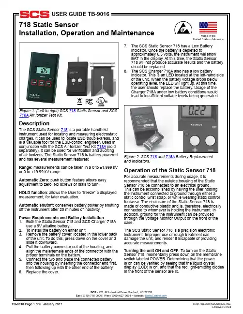
Figure 1. (Left to right) SCS 718 Static Sensor and SCS 718A Air Ionizer Test Kit.718 is a portable handheld instrument used for locating and measuring electrostatic charges. It can be used to locate ESD trouble-areas, and is a valuable tool for the ESD-control engineer. Used in conjunction with the SCS Air Ionizer Test Kit 718A (sold separately), it can be used for verification and auditing of air ionizers. The Static Sensor 718 is battery-powered and has several measurement features:measurements can be taken in a 0 to ±1.999 kVThe SCS Static Sensor 718 has a Low Batteryindicator. Once the battery is depleted toapproximately 6.5 volts, the instrument will showBAT in the display. At this time, the Static Sensor718 will not produce accurate results and the batteryOperation of the Static Sensor 718For accurate measurements during usage, it is recommended that the outside housing of the Static Sensor 718 be connected to an electrical ground.This can be accomplished by having the user holding Figure 2. SCS 718 and 718A Battery Replacementand Indicators.Made in theUnited States of AmericaTo shut off the Static Sensor 718, momentarily press down on the membrane switch labeled POWER. Determining that the power is off can be verified by seeing that the liquid-crystal display (LCD) is off. Making Electrostatic Voltage Measurements: hold the instrument 1-inch (2.54 cm) away from the object being measured. The display will update with the voltage measurement in kilovolts. If the measured voltage is greater than the measurement range of the instrument, a -1. Will be displayed. At this time, switch to a greater range. If over-ranging occurs even with the high range activated, the static charge on the object cannot be measured with the Static Sensor 718.Measurement Range: all measurements are in kilovolts (kV) as stated on the front label of the unit. The StaticSensor 718 has two measurement ranges: 0 to ±1.999kV and 0 to ±19.99 kV. The unit’s current measurementrange mode can be verified by checking the display.Three digits following the decimal point indicate that theunit is in 0 to ±1.999 kV range. Two digits following thedecimal point indicate that the sensor is in 0 to ±19.99kV range. To change between measurement ranges, press the RANGE/HOLD button once, momentarily.HOLD Function: in the event that the user wishes to freeze the current measurement, the HOLD function of the Static Sensor 718 may be used. Simply press the HOLD switch momentarily and the currently displayed voltage will be frozen. A HOLD notice will also bedisplayed to alert the user that the instrument is currently in HOLD status. To unfreeze the display and return tofloating measurement, momentarily press the HOLDswitch once again.Note: During HOLD condition the distance indicatingLED’s are turned off.Zero Adjustment: the SCS Static Sensor 718 has azero adjustment function, which sets a zero referencepoint for all subsequent measurements. This zeroreference can be set by pointing the instrument at aknown zero-voltage surface, and holding down the RANGE/ZERO button for longer than 3 seconds. After 3 seconds, the display will flash and adjust to zero. Repeat this step for both the low and the high ranges. The zero adjustment should be performed every time the unit is turned on.Measurement Accuracy: Distance Indicator: theStatic Sensor 718 is factory calibrated to give accurate measurements when it is placed one inch (2.54 cm) away from the object to be measured. To assist the user in gauging this distance, two light-emitting diodes (LED’s) are present on the front face of the instrument. These LED’s emit two red, bull’s-eye targets on thesurface of the object being measured. As the instrument gets closer to the one inch measurement distance, the bull’s-eyes begin to converge. When they converge and become one, the instrument is approximately one inch away, and the measurement can be made. For more accurate measurements, it is recommended that the user manually measure the distance between the front housing of the instrument and the object being measured.Accuracy and Size of Object to be Measured: the minimum surface area on an electrostatically chargedobject which can be accurately measured is a 5 squareinch (32.3 cm 2) area.Measurements from Greater than One Inch (2.54 cm) Away: in the event that a one inch separation between object-to-be measured and the Static Sensor 718 cannot be achieved, it is possible to get approximate readings.Continuous Output: an output jack is provided on the front of the SCS Static Sensor 718. This output can be used to feed a continuous signal into a data storage device for continuous monitoring of measured voltages. Please use a 3/32 inch (2.5 mm) mono-phone plug to connect into the output jack. The output signal is dependent on the measurement range currently selected. For the low range, the output signal is 1/1000 of the measured electrostatic voltage. For the high range, the output signal is 1/10,000 of the measured voltage.Figure 4. 718 Static Sensor showing hold function and Figure 5. 718 Static Sensor has a continuos output range.Figure 3. Using 718 Static Sensor to take measurements.Automatic Shut-Off: the Static Sensor 718 willautomatically shut-off 20 minutes after the last switch activity. This is done in order to conserve battery power. In the event that the user needs to have the unit stay ON continuously, when turning the unit on press the POWER AND RANGE switches simultaneously. This deactivates the Automatic Shut-Off feature. The BAT indicator will then flash three times to indicate that the automatic shut-off features has been disabled. The Automatic Shut-Off feature will reset itself the next time the instrument is turned on.Operation and Use of SCS Air Ionizer Kit 718A It is recommended that the user be familiar with ionizer test standards ANSI/ESD S3.1 and draft standard ANSI/ESD SP3.3 if the Air Ionizer Test Kit 718A is used to perform verification testing on ionizer performance.Assembly: slide the charge plate over the Static Sensor 718 until it stops. The charge plate slides onto the lower groove, on the sides of the Static Sensor 718.Charging the Plate: holding the Static Sensor 718 (with charge plate attached) in one hand, use the other handto touch the probe of the SCS Air Ionizer Test Kit 718Ato the charge plate. Press either the + button (for apositive voltage) or the – button (for a negative voltage), then remove the probe from the charge plate. Be sureto keep the button pressed while removing the probefrom the charge plate. The display on the Static Sensor 718 will indicate a positive or negative charging voltage (1.1kV minimum). If a voltage of less than ±1.1kV is displayed, check to see if the low battery indicator on the SCS Charger 718A is illuminated. If illuminated, replace the battery in the charger. If the unit continues to supply an incorrect voltage to the charge plate, please contact SCS for additional instructions.Testing ionizer discharge time: after charging the plate, hold the SCS Static Sensor 718 approximately one foot (30.5 cm) away from the ionizer. Monitor the display to see how quickly the 1.1 kV charge is dissipated to 0.1 kV. The speed at which this occurs (the discharge time) indicates how well the ionizer is operating. Please referto the specific ionizer’s operating manual or consultwith the ionizer manufacturer to determine what thisdischarge time should be. Repeat this procedure for both a positively and a negatively charged plate.Testing Ionizer Discharge Time: after charging theplate, hold the SCS Static Sensor 718 approximately onefoot (30.5 cm) away from the ionizer. Monitor the displayto see how quickly the 1.1 kV charge is dissipated to 0.1 kV. The speed at which this occurs (the discharge time) indicates how well the ionizer is operating. Please refer to the specific ionizer’s operating manual or consult with the ionizer manufacturer to determine what thisdischarge time should be. Repeat this procedure for botha positively and a negatively charged plate.Testing ionizer offset balance: zero the charge plateby touching it with a grounded object. This can either be the finger of a grounded person or some other item which is connected to electrical ground. In either case, zeroing the charge plate should make the display on the Static Sensor 718 read zero. Hold the Static Sensor 718 approximately one foot (30.5 cm) in front of the ionizer. Monitor the display. The value displayed is the offset balance of the ionizer, which is the difference between the number of positive and negative ions being emitted. Please refer to the specific ionizer’s operating manual or consult with the ionizer manufacturer to determine what this offset balance should be.Service/Calibration Service and Repair: in the event that you believe the Static Sensor 718 or the SCS Air Ionizer Test Kit 718Ais in need of repair, please contact your local SCS representative for troubleshooting help, and, as needed, repair information. There are no user-serviceable parts on either product. Figure 6. 718 Static Sensor charging plate in use.Figure 7. Testing Ionizer Offset Balance.Figure 8. 718 Static Sensor on test fixture.Static Sensor adjustable screw for display.。
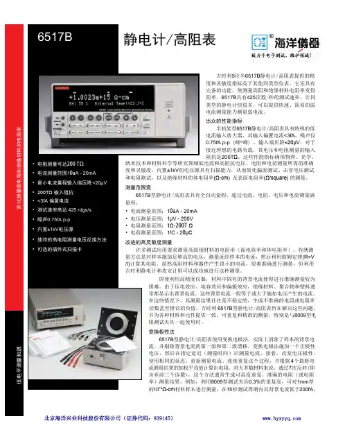
吉时利5位半6517B 静电计/高阻表提供的精度和灵敏度指标高于其他同类型仪表。
它还具有完备的功能,使测量高阻和绝缘材料电阻率变得简单。
6517B 具有425读数/秒的测试速率,比同类型的静电计快很多,可以提供快速、简易的弱电流测量能力测量弱电流。
出众的性能指标半机架型6517B 静电计/高阻表具有特殊的低电流输入放大器,其输入偏置电流<3fA ,噪声仅0.75fA p-p (峰-峰) ,输入端压降<20μV 。
对于接近理想的电路负载,其电压和电阻测量的输入阻抗是200T Ω。
这些性能指标确保物理、光学、(R=V . 6517B 型静电计/高阻表旨在解决这些问题,8009型电4个最新电7次反转(即8009型测试夹具0.3%的重复度,可对1mm 厚15秒测试周期内其背景电流低于200fA 。
(Ω-cm) 及表面电阻率(Ω/square) 的测量。
低电平测量和源静电计/高阻表与数字多用表类似的简单操作6517B 型静电计/高阻表采用与数字多用表类似的简易操作,可通过前面板,利用单一按钮控制电阻测量等重要功能。
还可以通过内置IEEE-488接口实施控制,因此,可利用计算机控制器通过总线对所有功能进行编程。
高精度高阻测量6517B 型静电计/高阻表的诸多特性和能力有助于确保高阻测量应用的准确度。
例如,其内置电压源简化了绝缘器电阻率和所用电源电压电平之间关系的确定。
它还非常适合电容器泄漏和绝缘电阻测量、印刷电路板表面绝缘电阻测试、电阻器电压系数测试以及二极管泄漏特性分析。
温度和湿度测试湿度和温度可能严重影响材料的电阻率值。
为了帮助您准确比较在不同情况下测得的读数,6517B 型静电计/高阻表提供内置K 型热电偶和一个可选的6517-RH 型相对湿度探头。
其内置数据存储缓冲器允许记录和调用具有时间、温度和相对湿度Stamping 的读数。
附件扩展测量能力利用多种可选附件,可以扩展6517B 型静电计/高阻表的应用,并改进其性能。
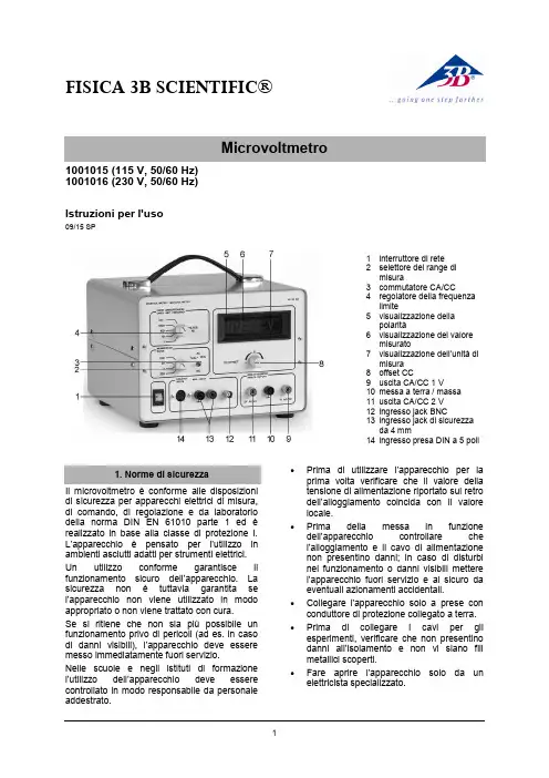
FISICA 3B SCIENTIFIC®11001015 (115 V, 50/60 Hz) 1001016 (230 V, 50/60 Hz)Istruzioni per l'uso09/15 SP1 interruttore di rete2 selettore del range dimisura3 commutatore CA/CC4 regolatore della frequenzalimite5 visualizzazione dellapolarità6 visualizzazione del valoremisurato7 visualizzazione dell’unità dimisura 8 offset CC9 uscita CA/CC 1 V10 messa a terra / massa 11 uscita CA/CC 2 V 12 ingresso jack BNC13 ingresso jack di sicurezzada 4 mm14 ingresso presa DIN a 5 poliIl microvoltmetro è conforme alle disposizioni di sicurezza per apparecchi elettrici di misura, di comando, di regolazione e da laboratorio della norma DIN EN 61010 parte 1 ed è realizzato in base alla classe di protezione I. L’apparecchio è pensato per l’utilizzo in ambienti asciutti adatti per strumenti elettrici. Un utilizzo conforme garantisce il funzionamento sicuro dell’apparecchio. La sicurezza non è tuttavia garantita se l’apparecchio non viene utilizzato in modo appropriato o non viene trattato con cura.Se si ritiene che non sia più possibile un funzionamento privo di pericoli (ad es. in caso di danni visibili), l’apparecchio deve essere messo immediatamente fuori servizio.Nelle scuole e negli istituti di formazione l’utilizzo dell’apparec chio deve essere controllato in modo responsabile da personale addestrato.∙Prima di utilizzare l’apparecchio per la prima volta verificare che il valore della tensione di alimentazione riportato sul retro dell’alloggiamento coincida con il valore locale.∙Prima della messa in funzione dell’apparecchio controllare che l’alloggiamento e il cavo di alimentazione non presentino danni; in caso di disturbi nel funzionamento o danni visibili mettere l’apparecchio fuori servizio e al sicuro da eventuali azionamenti accidentali.∙ Collegare l'apparecchio solo a prese con conduttore di protezione collegato a terra. ∙Prima di collegare i cavi per gli esperimenti, verificare che non presentino danni all’isolamento e non vi siano fili metallici scoperti.∙Fare aprire l’appa recchio solo da un elettricista specializzato.3B Scientific GmbH ▪ Rudorffweg 8 ▪ 21031 Hamburgo ▪ Germania ▪ Con riserva di modifiche tecniche © Copyright 2015 3B Scientific GmbHL'apparecchio consente di misurare e amplificare tensioni continue e alternate estremamente piccole (max. 2 V), come ad es. tensioni a induzione, termiche e ottiche. La misurazione viene indicata su un display a LED. Inoltre è possibile collegare anche un misuratore dimostrativo. Il segnale di misura viene alimentato mediante un jack BNC o un jack di sicurezza da 4 mm. Un commutatore consente di eseguire misurazioni in CA o CC. Nell'ingresso di misura è possibile collegare un filtro per il livellamento del segnale o per la limitazione superiore della frequenza di misura. Si possono impostare 4 frequenze fisse. Il filtro consente di ridurre le tensioni di disturbo durante le misurazioni di tensioni continue e alternate. Una presa DIN supplementare permette di collegare facilmente delle sonde di Hall.L’apparecchio 1001015 è progettato per una tensione di rete di 115 V (±10 %), 1001016 per 230 V (±10 %).Tensione di uscita: 0 – ±2 V Corrente di uscita:max. 1 mAResistenza d'entrata: range CC: 100 k Ω range CA: 900 k ΩVisualizzazione misura: display LED a 3,5 cifre Collegamenti in ingresso: 2 jack di sicurezzada 4 mm ,jack BNC presa DIN a 5 poliCollegamenti in uscita: 3 jack di sicurezza da4 mmTensione di alimentazione: vedere sul retrodell’alloggiamentoFusibile primario: vedere sul retrodell’alloggiamentoDimensioni: 235 × 250 × 180 mm³ Peso: ca. 3,3 kg4.1 Funzionamento come misuratore CC ∙ Applicare la tensione di esercizio. ∙ Impostare il commutatore su CC.∙Impostare il range di misura (200 μV –200 mV).∙ Mettere in cortocircuito l’ingresso e regolare il punto zero con l’offset CC.∙ Rimuovere il cortocircuito e collegare ilcarico all’ingresso.4.2 Funzionamento come misuratore CA ∙ Applicare la tensione di esercizio. ∙ Impostare il commutatore su CA.∙ Impostare il range di misura (200 μV –200 mV).∙Collegare il carico all’ingresso.4.3 Funzionamento come amplificatore dimisura CC∙ Applicare la tensione di esercizio. ∙ Impostare il commutatore su CC.∙ Impostare il range di misura (200 μV –200 mV).∙ Mettere i n cortocircuito l’ingresso e regolare il punto zero con l’offset CC.∙Rimuovere il cortocircuito e collegare il misuratore dimostrativo (visualizzazione analogica, range di misura fino a 2 V) all’uscita.∙Collegare il carico all’ingresso.4.4 Funzionamento come amplificatore dimisura CA∙ Applicare la tensione di esercizio. ∙ Impostare il commutatore su CA.∙ Impostare il range di misura (200 μV –200 mV).∙Collegare il misuratore dimostrativo (visualizzazione analogica, range di misura fino a 2 V) all’uscita.∙Collegare il carico all’ingresso.∙ Smaltire l'imballo presso i centri di raccolta e riciclaggio locali. ∙Non gettare l'apparecchio nei rifiuti domestici. Perlo smaltimento delle appare- cchiature elettriche, rispet- tare le disposizioni vigenti a livello locale.∙Non gettare le batterie esaurite nei rifiuti domestici. Rispettare le disposizioni legali locali (D: BattG; EU: 2006/66/EG).。
防爆型静电电压表一、工作原理静电主要是指不同物体紧密接触并迅速分离,由于两种物体对电子约束能力不同,物体间发生电子转移,从而使物体分别带上不同种电荷的现象。
产生静电的原因既有物体内部原因,又有外界作用。
从而又分成摩擦带电、附着带电、感应带电、极化带电等情况。
本仪器使用大规模集成电路将模拟量转化为数字量在液晶显示器上显示。
二、应用范围可能存在静电的作业有:1)石油、化工、粮食加工、粉末加工、管道输送气体、液体、粉尘等。
2)气体、液体、粉尘的喷射(冲洗、喷漆、泄露)。
3)皮带输送。
4)物料搅拌、混合、过滤等。
5)高速行驶的交通工具。
6)人体静电(行走、脱衣、梳理毛发、用有机溶剂洗衣等)。
在一些具有可燃性气体或粉尘的场所,静电是绝对要禁止的,而静电又往往无法发现和感觉到,对于管道或皮带的输送、物料的搅拌或人体上产生的静电,是我们日常检查的重点之一。
另外,在怀疑是静电火灾时,也需要对怀疑可以产生静电的同类物质进行测量,以便确认产生静电的可能性。
三、静电火灾产生的条件1)现场要有能够产生静电的条件。
2)静电的积累足以产生放电的能量。
3)具有带电体放电的条件如放电对象、放电距离。
4)放电能量大于被引燃物的最小点火能量。
5)放电点周围存在处于爆炸极限范围内的混合性气体或粉尘。
上述静电火灾判定条件中,有的又取决于许多因素,故要分别进行讨论。
四、仪器特性量程:0~±30KV(测量距离2cm)●精度:±10%●分辨率:10V●功耗:≤30mw五、仪器使用方法1)打开电源开关,接通电源;2)距离带电体30cm以上处按调零开关调零,消除感应屏上的静电。
3)将电压表探头由30cm处靠近被测物体规定的距离处,读取电压值(为液晶显示值×10);4)不要用手去触摸感应屏,以免损坏输入器件。
5)液晶显示器数字暗淡,显示不稳定或测试数据不准确,应检查9V积层电池,当电压低于8.8V或使用半年以上时应更换电池。
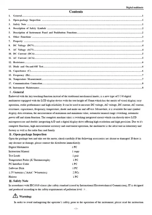
Contents1. General (1)2. Open-package Inspection (1)3. Safety Note (1)4. Description of Safety Symbols (2)5. Description of Instrument Panel and Pushbutton Functions (2)6. Other Functions (3)7. Property (3)8. DC Voltage (DCV) (4)9. AC Voltage (ACV) (4)10. DC Current (DCA) (5)11. AC Current (ACA) (5)12. Resistance (6)13. Diode and On-and-Off Test (6)14. Capacitance (C) (6)15. Frequency (Hz) (7)16. Temperature Measurement (7)17. Communication Connection (8)18. Instrument Maintenance (8)Ⅰ. GeneralEndowed with the key touching function instead of the traditional mechanical knobs, is a new type of 3 5/6 digital multimeter equipped with the LCD display device with the text height of 33mm which has the merits of visual display, easy operation, stable performance and high reliability. It can be used to measure DC voltage, AC voltage, DC current, AC current, resistance, capacitance, frequency, temperature, diode and make on-and-off test. Meanwhile, it is available for unit symbol display, data retention, the measurement of maximum and minimum value, automatic/manual range switching, automatic power off and alarm function. The complete machine takes a switching integrated circuit which can directly drive LCD microprocessor and double-integrating A/D and a digital display drive offering high resolution and high precision. Due to it's complete functions, high measurement accuracy and convenient operation, the multimeter is the ideal tool in laboratory and factory as well as for radio fans and family.Ⅱ. Open-package InspectionOpen the package box and take out the meter, check carefully if the following accessories are absent or damaged. If there is any absence or damage, please contact the distributor immediately.Digital Multimeter 1 PCInstruction Manual 1 copyTest Leads 1 pairTemperature Probe (K-Thermocouple) 1 PCPC Interface Cable 1 PCSoftware Disk 1 PC1.5V batteries ("AAA" 7# batteries) 2 PCsHolster 1 PCⅢ. Safety NoteIn accordance with IEC1010 clause (the safety standard issued by International Electrotechnical Commission), IT is designed and produced according to the safety requirements of pollution level Ⅱ.Warning:In order to avoid endangering the operator’s safety, prior to the operation of the instrument, please read the instructionmanual carefully, and conform to the safety warning information and operation instruction strictly to use the instrument.1.When voltage above 30V, current above 10mA, AC power line with inductive load or power line during electricfluctuation is measured, please beware of electric shock.2.Prior to measurement, check if the measurement function is in conformity with the LCD display, and if thepushbutton switch is at the trigger position. Check if the meter pen is contacted reliably, connected correctly, and grounded well and etc. in order to avoid electric shock.3.Only if the meter is used with the matched meter pen, can it meet the requirement of safety standard. When the lineof the meter pen is damaged, it is necessary to replace another one of the same model or the same electrical specification.4.Don’t use other unconfirmed or disapproved protector tube to replace the protector tube inside the meter. Only theprotector tube of the same model or same specification can be replaced. Before the replacement, the meter pen must leave the measuring point and ensure there is no any signal at the input terminal.5.Don’t use other unconfirmed or disapproved battery to replace the battery inside the meter. Only the battery of thesame model or same electrical specification can be replaced. Before the replacement, the meter pen must leave the measuring point and ensure there is no any signal at the input terminal.6.When the electrical measurement is made, never let your body get in touch with the ground directly, and don’t touchuncovered metal terminal, output port, lead clamp and etc. where earth potential may exist. Dry clothes, rubber shoes, rubber cushion and other insulating material are usually used to keep your body insulated against the ground.7.Don’t store and use it in the high-temperature, high-humidity, inflammable and strong magnetic field environment.8.It may do damage to the meter and endanger the operator’s safety if the voltage value beyond the permitted ultimatevoltage value is measured. The ultimate voltage value permitted for measurement is marked on the instrument panel, and never measure the value exceeding the standard. Don’t input the ultimate value out of regulation in order to avoid electric shock and the damage to the meter.9.When the meter pen is inserted into the current socket, don’t measure any voltage for fear that the meter should bedamaged and the operator’s safety be endangered.10.Don’t try calibrating or repairing the meter. When it is indeed necessary for that, only the qualified professionalpersonnel who have had special training or gained approval can make it.11.During measurement, the requirement of measurement function must be in accordance with LCD display. Please besure to disconnect the line of the meter pen with the measured object first and ensure there is no any input signal. It is forbidden to switch the function/range selection switch during measurement12.When “””is shown on LCD display, please replace battery immediately to ensure the measurement precision.13.It is not allowed to insert the meter pen into the current terminal to measure voltage!14.Please don’t change the circuits of the meter freely for fear that the meter be damaged and the safety be endangered.Ⅳ. Description of Safety SymbolsⅤ. Description of Instrument Panel and Pushbutton Functions1.Instrument model.2.LCD display area.3.Function button: Used to select various measurement functions.3-1“Hold” backlight switch and reading-keeping switch. If the switch is pressed over 2 seconds, the backlight turns on.Further press the switch over 2 seconds, the backlight turns off or automatically turns off after 10 seconds. Pressing theswitch within 2 seconds could lock or unlock the data retention. Press the switch once to lock and press it again to unlock.between the frequency and the Duty Cycle.Press the key in thegear of AC Voltage or AC Curren can switch among the voltage,current, frequency and duty cycle.3-3 MAX/MIN: The maximum value and minimum value.Press thefunction button and enter MAX mode, in which the maximumvalue is held; press the button again to enter MIN mode, in whichthe minimum value is held. After the MAX/MIN mode is entered,the display device indicates the MAX/MIN value. No analog bardisplay and auto power off function in this working environment.Pressdown MAX/MIN button for 2 seconds, and then exit from MAX or MIN test.3-4 Range: Automatic/Manual Range Switch. Pre-set it to automatic range when the device starts up, then switch it to manual range. In the mode of manual range, press the “RANGE” button once, it will skip to the previous shift. When it goes to the highest shift, it goes back to the lowest shift when the button is pressed again. The procedure repeats again in the same order. Press the button over 2 seconds, it will exit from manual range and enter the state of automatic range measurement.3-5 REL: Relative Value Measurement. Press this key to show the relative value measurement, press again to cancel the relative value measurement. The procedure repeats in the same order. Press this key over 2 seconds, it will switch to RS232, which can be showed on the LCD screen and the RS232 data transmission is thus open. Further press the key over 2 seconds, the RS232 icon diappears on the LCD screen. Now the RS232 data transmission terminates. The procedure repeats.4. “POWER”is the power switch.5. Function Selection Button.7. 10A current input jack: Measure the positive input terminal of 10A shift AC/DC current, and insert red meter pen.8. mA input port: Measure the positive input terminal of AC/DC.9. COM input port: Measure the negative input terminal, and insert black meter pen.Ⅵ. Other Functions1.Automatic power offAfter the meter is stopped for 15 minutes, it will cut off power automatically (power off), and then enter the dormant(power off) state. The built-in buzzer will send out warning tone in one minute before it powers off. If you want to restartpower(power on), please press the power switch. If you want to cancel antomatic power-off, please press “REL” key over 2seconds until the RS232 symbol appears. Meanwhile the “APO” symbol will be also turned off..ⅦProperty1. General features1-1 Display mode: LCD1-2. Maximum display: 5999.3 5/6 display automatic polarity display and unit display.1-3. Analog bar. 30 times/sec, display of 61analog bars.1-4. Measurement mode: dual integration A/D conversion.1-5. Sampling rate: About 3 time/s.1-6. Over range: Display “OL”1-7. Low voltage display: about 2.4v, the symbol displayed.1-8. Working temperature: :0~40℃1-9 Storage temperature: -10~50℃, relative humidity <80%1-10. Power: Two 1.5v batteries ("AAA" 7# batteries)1-11 V olume (Dimensions): 185mm×91mm×49mm(Length*width *height)1-12 Weight: About 410g (including battery )2.Technical features.2-1. Accuracy: ±(a% reading + d digits), the ambient temperature for ensuring accuracy: 23±5℃, relative humidity <75%. 2-2. The warranty period of calibration is one year from ex-factory date.. DC Voltage (DCV)Ⅷ1.Press "AC/DC", select automatic measurement of DC voltge., and respectively plug in the red and black meter pens into the terminals of “VΩHz”and“COM”, as shown in the following diagram.2.The initial state of the meter is the DC voltage automatic measurement mode, which shows the symbols of “DC”“AUTO”“APO”. Press “RANGE” is to select manual range mode; Press “MAX/MIN” once to show the Max measurement value. Press “MAX/MIN” again to show the Min measurement value. Press “MAX/MIN” over 2 seconds is to cancel the measurement of the MAX/MIN value.3.Touch the measuring point with the meter measuring pen and connect it in parallel to the circuit being tested, and the polarity of the red meter pen wire and the tested voltage value are spontaneously displayed on the display.Caution:a)Voltages over DC1000V or AC750V cannot be tested.b) When measuring high voltages, special precautions must be taken to avoid electrical shock.When measurement is completed, immediately disconnectthe meter pen and the measured circuit.c) In case “OL” is displayed for manual range mode, it indicated the range has beenRange Accuracy Resolution600mV±(0.5%+4d) 0.1mV6V 1mV60V 10mV600V 100mV1000V ±(1.0%+4d) 1VInput impedance: 600mV range>60MΩ,the others are 10MΩ. Overload protection: 1000VDC or 750V alternative peak. IX. AC Voltage (ACV)1.Circularly press the “AC/DC”key until it selects the AC Voltage automatic measurement mode. Meanwhile, the symbol “AC”,“AUTO”,“APO”will appear on the LCD. Respectively plug in the red and black meter pens into the terminals " and "com". See the picture below.2.The initial state of the meter is automatic range, which shows "AUTO" symbol.Press the "Range" key and switch it to manual range mode. In the AC mode ofautomatic/manual range, the frequency/ duty cycle can be measured bypressing “Hz/DUTY”. However, the frequency response now is low ,which is suitable for the measurement of high voltage and low frequencyin the environment of magnetic field interference such as 220V/50Hz-400Hz,380V/50Hz-400Hz.Caution:it indicated the range has been exceeded and it is necessary to select higher range mode to complete this measurement.Range Accuracy Resolution6V±(0.8%+10d) 1mV60V 10mV600V100mV 750V ±(1.0%+6d) 1VInput impedance: 10MΩ.Overload protection :1000VDC or 750V alternating peak.Display :Mean value response(calibrated with sine wave).Frequency response :(40-400)Hz.Duty Cycle Display: (0.1%-99.9%).X. DC Current (DCA)1. Press the ““ button. Plug the black meter pen into the terminal of “COM” and the red meter pen nto the terminal of “mA” or “10A”. See the picture below.2. Circularly press thebutton or button. Selectautomatic DC 600aA and 10A current to test. The “DC ”、“AUTO ”、“APO ”symbols will appear on the LCD screen. 3.In case “OL” is displayed on the display, it indicates the current beingmeasured has exceed the current range, and please select higher rangesfor measurements.Caution:a )At the 10A mode, current bigger than 10A cannot be measured, and at mA mode, the current bigger than 600 mA cannotbe measured. Otherwise this will lead to the burning of the fuse or damage the instrument.b) When the meter pen is plugged in the input terminal of the current, it is strictly prohibited to have the meter pen connected in parallel on any circuits.RangeAccuracy Resolution 60mA±(1.0%+10d) 10μA 600mA100μA 6A±(1.2%+10d) 1mA10A 10mA The maximum input current: 10A (not exceeding 15s))Overload protection: 0.6A/250V fuse; 10A/250V fuse.XI. AC Current (ACA)1. Press the ““ button. Plug the black meter pen into the hole of “COM” and the red meter pen into the hole of “mA” or “10A”. See the picture below.2. Circularly press thebutton or “ button. Select automatic AC 600aA and 10A current to test. The “AC ”、“AUTO ”、“APO ” symbols will appear on the LCD screen.3. In case “OL” is displayed on the display, it indicates the current being measured has exceed the current range, and please select higher ranges for measurements.Caution:a )At the 10A mode, current bigger than 10A cannot be measured, and at mA mode, the current bigger than 600 mA cannotbe measured. Otherwise this will lead to the burning of the fuse or damage the instrument.b) When the meter penis plugged in the input terminal of the current, it is strictly prohibited to have the meter pen connectedin parallel on any circuits.RangeAccuracy Resolution 60mA±(1.5%+10d) 10μA 600mA100μA 6A±(2.5%+15d) 1mA10A 10mA The maximum input current: 10A (not exceeding 15s))Overload protection: 0.6A/250V fuse; 10A/250V fuse.Frequency response: 40-400Hz. Duty Cycle Display: (0.1%-99.9%).”and “COM”.“ button and select resistance measurement.In automatic resistance measurement mode, you could select manualmeasurement by pressing "Range".Caution:a) When measuring the capacity, all the powers within the tested circuits must be disconnected and the capacitance shall be sufficiently discharged.b) When measuring the resistance, any occurrence of voltage may Lead to inaccurate readings, and if the 250V protectionvoltage is exceeded, it may damage the meter or threaten the safety of the user.c) When the range of 600Ω is in use, first sort-circuit the meter pens and measure the resistance of the lead wires and then deduct it in the actual measurement.Range Accuracy Resolution600Ω±(0.8%+5d) 0.1Ω6kΩ±(0.8%+4d)1Ω60kΩ10Ω600kΩ100Ω6MΩ1kΩ60MΩ±(1.2%+10d) 10kΩOpen circuit voltage: 600mV.Overload protection: 250V DC or AC peak values.” button to select the diode or buzzer measurement. In Diode mode, LDC screen displays " " and voltage symbol, and the buzzer symbol " " is also displayed on the screen.3. Connect the red meter pen to the positive of the diode, the black meter pen to the negative of the diode.Caution:a) In case the diode is open circuit or the polarities are connected reversely, “OL” will be displayed on the screen.b) When checking the diode, all the powers within the tested circuits must be disconnected and the capacitance shall be sufficiently discharged.c) When the measurement is completed, immediately disconnect the meter and the measured circuit.Overload protection: 250V DC or AC peak value.XIV" button and respectively plug in the red and black meter pens into “ ”and“COM”.2. Circularly press "symbol will appear on the LCD screen. No manual measurement range and analog bar will be displayed in Capacity mode.Range Display valueMeasurementconditionDiode forwardvoltage dropForward DC currentis about 1.0mA, andbackward voltage isabout 3.0V.If Buzzer emits along sound and theresistance of thetwo points ismeasured as 30ΩOpen circuit voltageis about 1.2VCaution :a) When measuring the capacity, all the powers within the tested circuits must be disconnected and the capacitance shall be sufficiently dischargedb)When measuring big capacitors, it takes a longer time, about 100uF per 15 seconds. c) When the measurement is completed, immediately disconnect the meter and the measured circuit.RangeAccuracy Resolution 40nF±(5.0%+30d) 10pF 400nF±(3.5%+8d) 100pF 4μF1nF 40μF10nF 200μF ±(5.0%+10d) 100nF Overload protection: 250V DC or AC peak value.XV . Frequency (Hz)Respectively plug in the meter pen into “VΩHz”and“COM”.2. Have the testing end of the meter pen connected in parallel with the signal sources to be measured and read the results from the display. (Note: No analog bar will displayed in this mode)3. When testing frequency, press "Hz/DUTY" once to conduct duty cycle measurement. Press "Hz/DUTY" once more to enter the frequency status.4. Read the current results from the display.Caution :a) Do not input signals higher than 60V, otherwise it maydamage the instrument and pose dangers to human safety.b) After all the measurements are completed, it is necessaryto disconnect the meter pen and the tested circuit.RangeAccuracy Resolution 10Hz±(0.3%+2d) 0.001Hz 100Hz0.01Hz 1000Hz1Hz 10kHz10Hz 100kHz100Hz 1MHz1kHz 20MHz 10kHz Input sensitivity: 1.5V effective value. Overload protection: 250VDC or alternating peak symbol will be displayed. Further press ", it will be displayed as Fahrenheit. The procedure repeats in the" and " COM ".3. Put the induction end of temperature probe on the surface of the tested object.See the picture on the right.4. Read the current testing results from the display.Caution :a) When the input end is open circuit, it indicates normal temperature.b) Do not change the temperature sensor at random, otherwise the accuracy ofmeasurement can not be guaranteed.c) Do not input voltage in temprature mode, otherwise the meter may be damaged.。
声明武汉市华天电力自动化有限责任公司版权所有,保留所有权利。
本使用说明书所提及的商标与名称,均属于其合法注册公司所有。
本使用说明书受著作权保护,所撰写的内容均为公司所有。
本使用说明书所提及的产品规格或相关信息,未经许可,任何单位或个人不得擅自仿制、复制、修改、传播或出版。
本说明书所提到的产品规格和资讯仅供参考,如有内容更新,恕不另行通知。
可随时查阅我公司官网:除非有特殊约定,本说明书仅作为使用指导,本说明书中所有陈述、信息等均不构成任何形式的担保。
销售热线:027-********/87497907/87455189E-mail:*****************服务承诺感谢您使用本公司的产品SGB-C系列交直流数字高压表。
在初次使用该仪器前,请您详细阅读使用说明书,将可帮助您正确使用该仪器。
我们深信优质、系统、全面、快捷的服务是事业发展的基础。
经过多年的不断探索和进取,我们形成了"以客户为核心、以质量为企业第一生命"的服务理念。
立足现代电测高科技,以更好的产品质量,更完善的售后服务,全力打造技术领先、质量领先、服务领先的知名电测品牌企业。
坚持"用户第一"的原则,构建良好的销售服务体系,为客户提供优质的售前、售后服务!清单导读本说明书装箱清单是标准配置,如有差异请核对供销合同,武汉市华天电力自动化有限责任公司保留修改的权利。
注:详细清单见本说明书最后一页“装箱清单”。
销售热线:027-********/87497907/87455189E-mail:*****************销售热线:027-********/87497907/87455189E-mail:*****************为了避免可能发生的危险,请阅读下列安全注意事项。
本产品只可使用我公司产品专用并且符合本产品规格配套要求的附件。
防止电击和火灾及人身伤害!只有经过专业培训的人员才能操作此仪器/仪表。
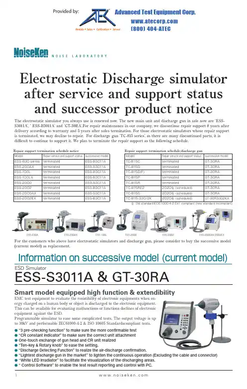
1w w w.n o i s e k e n.c o mThe electrostatic simulator you always use is renewed now. The new main unit and discharge gun in sale now are `ESS-S3011A`, ` ESS-B3011A` and `GT-30RA`.For repair maintenance in our company, we discontinue repair support 8 years after delivery according to warranty and 5 years after sales termination. For those electrostatic simulators whose repair support is terminated, we may decline to repair. For discharge gun 'TC-815 series', as there are many discontinued parts, it is difficult to continue to support it. We plan to terminate the repair support as the following schedule.ESD SimulatorESS-S3011A & GT-30RASmart model equipped high function & extendibilityInformation on successive model (current model)Repair support termination schedule:discharge gunModelRepair service and support statussuccessive modelTC-815C terminated GT-30RA TC-815D terminated GT-30RA TC-815D(F)terminated GT-30RA TC-815P terminated GT-30RA TC-815R terminatedGT-30RA TC-815RE22020年(scheduled)GT-30RA TC-815S2020年(scheduled)GT-30RA TC-815-330/2K2020年(scheduled)GT-30R3302KA※Old standard:IEC61000-4-2 Ed1 compliant (new standard incompliant)Repair support termination schedule noticeModelRepair service and support status successive modelESS-630 series terminated ESS-B3011A ESS-200AX terminated ESS-S3011A ESS-100L terminated ESS-B3011A ESS-100LA terminated ESS-B3011A ESS-2000terminated ESS-S3011A ESS-2002terminated ESS-B3011A ESS-2000AX terminated ESS-S3011A ESS-2002EXterminatedESS-B3011AFor the customers who above have electrostatic simulators and discharge gun, please consider to buy the successive model(current model) as replacement.ESS-630A ESS-200AX ESS-100L ESS-2000ESS-2002ESS-2000AX/2002EXEMC test equipment to evaluate the resistibility of electronic equipments when en-ergy charged on a human body or object is discharged to the electronic equipment.This can be available for evaluating malfunctions or functions declines of electronic equipment against the ESD.Programmable simulator to ease some complicated tests. The output voltage is up to 30kV and performable IEC61000-4-2 & ISO 10605 Standardscompliant tests.●“3 pre-checking function” to make sure the more confirmable test ●“CR constant indicator” to make sure the correct unit attachment ●One-touch exchange of gun head and CR unit realized ●“Ten-key & Rotary knob” to ease the setting.●“Discharge Detecting Function” to realize the air-discharge confirmation.●“Lightest discharge gun in the market” to lighten the continuous operation (Excluding the cable and connector)●“White LED Irradiator” to facilitate the visualization of the discharging areas.●“ Control Software” to enable the test result reporting and control with PC.Provided by:Advanced Test Equipment Corp .® (800) 404-ATECRentals • Sales • Calibration • ServiceESD SimulatorESS-B3011A & GT-30RACost-oriented basic model ESD Simulator the light weight discharge gun attach-able.The output voltage can be selected either max. 30kV (B3011A) or max.16kV (L1611A) and compliant to both EN/IEC61000-4-2 Standard (both B3011A and L1611A) and ISO10605 Standard (only B3011A).Cost-oriented Basic modelsESS-S3011A & GT-30RAParameter Specification Polarity Positive / Negative Output voltage 0.20kV ~ 30.0kV±5% (30.5kVmax) ~10.0kV : 0.01kV step ~30.0kV : 0.1kV step Repetition cycle 0.05s ~ 600s±10% / Manual Set step : 0.01s (0.05 ~ 9.99s), 0.10s (10.0 ~ 600.0s)No. of time of discharge 1~60,000 times, Preset 1 time step or continuous preset Discharge mode Contact discharge / Air discharge Radiation level mode NORMAL mode / EXTRA mode Trigger mode Gun trigger / Main trigger / External trigger Operation panel Color LCD / Push-buttons (Partially lighting)Gun holder Standard attached (to hold the discharge gun Model GT-30RA)Radiation mode select switch Extra / Normal switching function built-inDischarge detection Discharge detection function in air-discharge equipped Pre-checking function Following 3 steps function equipped (by user operation. Not the calibration but just checking) SETP1 : High voltage output checking STEP2 : Withstanding voltage checking STEP3 : Discharge relay operation checking CR & Gun head checking CR constant and gun head recognizable (with an indicator to prevent the wrong combination)Parameter Specification"IEC STANDARD" Contact discharge mode : 2.0kV, 4.0kV, 6.0kV and 8.0kV step test mode Air discharge mode : 2.0kV, 4.0kV, 8.0kV and 15.0kV step "MANUAL" Contact / Air discharge mode, Arbitrary setting during 0.2kV~30.0kV test mode Sweeping function built-in, Recordable up to 99 units "SEQUENCE" Enables to operate units set in MANUAL mode continuously.test mode Max. 22 steps / 1 program and the programs recordable up to 20.Warning lamp Lighting at voltage output from the generator. Blinking at electro-static dischargingCharge capacitor / resistor 150pF±10%, 330Ω±10%(Built-in CR unit for discharge gun GT-30RA)Charge resistor in generator 10MΩ(Totally 53Ω in combination with 43MΩ in discharge gun)*AUX connector D-SUB 15pins female connector (for connecting to patolight, automated ESD eliminator, external interlock input, external trigger input terminal)Optical communication Optical connector (serial interface) for connecting to PC connector Power supply / consumption AC100V~AC240V 50Hz / 60Hz ±10% 75VA Dimension Generator : (W)392mm X (H)312mm X (D)295.3mm (including gun holder) Discharge gun : (W)83.3mm X (H)217.2mm X (D)229.3mm Mass Generator : Approx. 7.5kg Discharge gun : Approx. 800g (excluding cable and connector)* The constant depends on combination with CR unit for the discharge gun● “Pre-checking function” taking the confirmable test into the account ● “Discharge Detecting Function” to realize the air-discharge confirmation.● “Lightest Discharge Gun in the market” to lighten the continual operation"● “White LED Irradiator” to facilitate the visualization of the discharging area.● “CR constant checking function” (No indicator) to make the correct unit attachment sure"● One-touch exchange of gun head and CR unit realizedParameter Specification Output voltage 0.20kV~30.0kV±5%(30.5kVmax) ESS-L1611A is 16kVmax Polarity Positive / Negative Repetition cycle 0.05s~9.99s±10%, 0.01s step / ManualNo. of time of discharge 1~999 times, Preset 1 time step or continuous preset Discharge mode Contact discharge / Air discharge Trigger mode Gun trigger / Main trigger Operation panel Indicator : 5X7 Dot matrix LED / Operation : Push buttons Radiation mode select switch Extra / Normal switching function built-inDischarge detection Discharge detection function in air-discharge equipped.Pre-checking function High voltage output checking function (by user operation. Not the calibration but just checking)CR & Gun head CR constant and gun head recognizable checking (to prevent the wrong combination without indicator)IEC LEVELContact discharge mode : 2.0kV, 4.0kV, 6.0kV and 8.0kV step Switching function Air discharge mode : 2.0kV, 4.0kV, 8.0kV and 15.0kV step)Parameter SpecificationWarning lamp Lighting at voltage output from the generator. Blinking at electro-static discharging Charge capacitor / resistor 150pF±10%, 330Ω±10% (Built-in CR unit for discharge gun GT-30RA)Charge resistor in generator 10MΩ (Totally 53Ω in combination with 43MΩ in discharge gun)*Power supply / consumption AC100V~AC240V ±10% 50Hz / 60Hz 62VA Dimension Generator : (W)270 X (H)263 X (D)200mm Discharge gun : (W)83.3 X (H)217.2 X (D)229.3mm Mass Generator : Approx. 4.8kg Discharge gun : Approx. 800g (excluding cable and connector)* Remote control function not built-in.* The constant depends on combination with CR unit for the discharge gun。
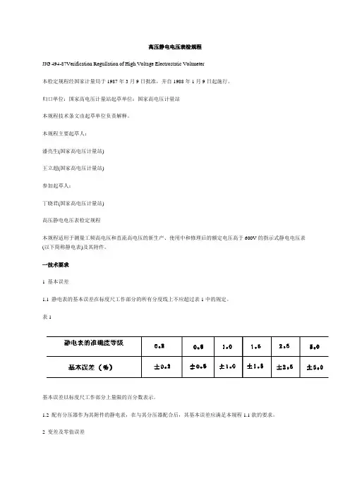
高压静电电压表检规程JJG 494-87Verification Regullation of High Voltage Electrostatic Voltmeter本检定规程经国家计量局于1987年3月9日批准,并自1988年1月9日起施行。
归口单位:国家高电压计量站起草单位:国家高电压计量站本规程技术条文由起草单位负责解释。
本规程主要起草人:潘亮生(国家高电压计量站)王立超(国家高电压计量站)参加起草人:丁晓君(国家高电压计量站)高压静电电压表检定规程本规程适用于测量工频高电压和直流高电压的新生产、使用中和修理后的额定电压高于600V的指示式静电电压表(以下简称静电表)及其附件。
一技术要求1 基本误差1.1 静电表的基本误差在标度尺工作部分的所有分度线上不应超过表1中的规定。
表1基本误差以标度尺工作部分上量限的百分数表示。
1.2 配有分压器作为其附件的静电表,在与其分压器配合后,其基本误差应满足本规程1.1款的要求。
2 变差及零值误差2.1 微型、小型和能耐受机械力作用的静电表,其指示值的变差不应超过其允许的基本误差绝对值的1.5倍。
其他静电表指示值的变差不应超过其基本误差的绝对值。
2.2 静电表的零值误差不应超过如下的规定:2.2.1 能耐受机械力作用的静电表、微型和小型的静电表、标度尺角度大于120°的静电表和张丝式静电表用公式⑴确定允许的零值误差:式中:K--静电表准确度等级的数值;L--标度尺的长度(mm)。
2.2.2 其他静电表为按⑴式确定的数值的一半。
2.3 通过改变电极距离转移量程的0.5级和0.2级的静电表,由于转移量程的操作造成任一个量程读数的分散性(以下简称分散性)不得大于其基本误差绝对值的40%。
3 倾斜误差将静电表自规定的工作位置,按表2所规定的角度向任一方面倾斜,其指标值的改变不应超过表1中的规定值。
指示值改变的表示方法与基本误差表示方法相同。
如静电表上未注明工作位置,则在垂直与水平两个位置都应符合本条要求。
·本安防爆,安全性好!·数字保持,读数方便!·数字显示,分辨率高!·测量准确,显示迅速!·体积小,重量轻!·欠压指示,确保准确!·用途广泛,携带方便!·耗电极小,使用方便!·可靠性高,保修两年!EST101型防爆静电电压表(使用说明书)北京市劳动保护科学研究所一. 概述EST101型防爆静电电压表是在吸收国内外先进静电仪表的基础上,经广大用户多年使用并多次改进的新型高性能、低价格静电电压表(静电电位计)。
本仪表防爆性能好,防爆标志为iaⅡCT6。
能在各类爆炸性气体(如汽油、二硫化碳、市用煤气、乙烯、乙炔、氢、苯等)中使用。
防爆合格证编号为:CJEx02.4.031。
符合国家标准要求。
本仪表适用于测量带电物体的静电电压(电位),如导体、绝缘体、及人体等的静电电位。
还可测量液面电位及检测防静电产品性能等。
广泛适用于石油、化工、油库、消防、电子、国防、航天、天然气、印刷、纺织、印染、橡胶、塑料、喷涂、医药等科研、生产、储运安全管理部门中有关静电的测量。
是现场静电检测的理想仪表二、特点●能在各类爆炸性环境中使用,防爆性能好,防爆标志为ExiaⅡCT6.防爆合格证编号为:CJEx02.4.031●数字显示,分辨率高。
●有读数保持功能。
读数准确方便。
●非接触式旧子测量,对被测物体影响小。
●测量准确迅速。
测量速率约3次/秒。
●体积小,重量轻,携带方便。
●耗电省,一节电池能连续工作达200小时,或间断约一年。
•有电池欠压显示,确保测量准确。
•使用大规模集成电路,可靠性高。
•用途范围广。
使用方便。
•保修两年,用户使用放心。
三。
主要技术指标1. 本质安全防爆型, 防爆标志:ExiaⅡCT6。
2.非接触式测量。
输入阻抗>1016Ω.输入电容<1PF。
3. 测量范围: ±100V - ±50KV。
(测量范围可以扩展)。
目录第一章概述----------------------------------------------------------------------------------- ------2 第二章规格和技术特性---------------------------------------------------------------------------2 第三章仪器结构及工作原理--------------------------------------------------------------------3 第四章安全注意事项------------------------------------------------------------------------------5 第五章使用与操作--------------------------------------------------------------------------------6第六章常见故障及其排除方法----------------------------------------------------------------10第七章检准方法----------------------------------------------------------------------------------10第八章配件----------------------------------------------------------------------------------------11第九章其他-----------------------------------------------------------------------------------------11附录-----------------------------------------------------------------------------------------------12第一章概述YH-8200型高绝缘电阻测量仪(高阻计)适用于测量绝缘材料、电工产品、各类元器件的绝缘电阻,与恒温水浴配套后,还能测量在不同温度下的塑料电线电缆(无屏蔽层)的绝缘电阻。
静电电压表静电电压表是静电测量仪表测量施加电压的两板上的静电力的大小或由该静电力产生的某一极板的偏移(或偏转)该静电力产生的某一极板的偏移(或偏转)来放映所加电压的大小的表计。
用于测量用于电力系统及电气、电子设备制造部门测量工频交流高电压和直流高电压。
静电电压表测量工频高电压时,测得的是电压的有效值。
静电电压表的几种结构静电电压测量仪表有接触式和非接触式,一般接触式静电电压表如FS3静电计的测量精度高些,但只能适用于测量金属体的静电电压或电位,而非接触式测量时勿需同带电体接触,不但能测量金属体的静电,也能测量绝缘体的静电,且对被测量物体影响小。
非接触式静电测量仪主要有振动电容式、直接感应式、旋转叶片式等几种结构。
1、振动电容式这种仪表如EST102振动电容静电计主要由测量探头、交流放大器、振荡器、相敏检波器、显示仪表、调零电源、稳压电源等组成。
探极是一可振动的金属片,由于机械振动,探极与被测带电体之间的电容周期性地变化,于是,在被测带电体静电感应的作用下,在探极上产生一个周期性变化的电压讯号。
因为交流讯号非常微弱,采用高输入阻抗的阻抗变换器接受汛号,经阻抗变换后输入给量程转换器。
交流放大器接受量程转换器的输出讯号,予以放大后还原成直流信号。
振动电容式仪表的探极上的交流讯号决定于被测带电体的电压和探极的振动,不随时间衰减,因此,这种仪表除可用作测量仪表外,还可用作固定接入的监测仪表。
而采用国际先进技术设计的振动电容式仪表还能在有带电粒子或离子如高压放电、离子风消电器产生的环境中稳定工作,也能在尘土较多,湿度较大的环境中稳定工作。
不会像直接感应式仪表那样产生漂移,也没有旋转叶片式仪表那样因电动机转动造成磨损而影响寿命和产生“反常”误差,更不会像集电式仪表测量电压那样对人体产生有害的心理作用和受空气流动的影响。
这种仪表是目前国际上技术先进的静电测量仪表,但成本高因而价格也高。
旋转叶片式这种仪表由测量探头,放大器、显示仪表等环节组成。
3B SCIENTIFIC ® PHYSICSElektrometer (230 V, 50/60 Hz) 1001025 Elektrometer (115 V, 50/60 Hz) 1001024Bedienungsanleitung02/15 Hh1 Steckplatz für SEG-Elemente2 Eingangsbuchse IN für Faraday-Becher3 Eingangsbuchse IN für SEG-Elemente4 Massebuchse (Bezugspunkt) für den Eingang 5Anschlussbuchse für Haltestab mit 4-mm Boh-rung6 Hohlbuchse für 12 V AC-Steckernetzgerät7 Betriebsanzeige 8 Offset-Einsteller des Elektrometers9 Massebuchse (Bezugspunkt) für den Ausgang 10 Ausgangsbuchse OUT 11 Steckernetzgerät1. SicherheitshinweiseElektrometer mit extrem hochohmigem, überspan-nungs-gefährdetem Spannungseingang:•Maximalwert der Eingangsspannung von ± 10 Vnicht überschreiten!Eine höhere Spannung ist nur dann zulässig, wennsicher gestellt ist, dass sie bei Berührung span-nungsführender Teile unverzögert auf den oben angegebenen Wert oder auf niedrigere Werte her-abgesetzt wird. Dies ist bei den im Text genannten Spannungsquellen gewährleistet.•Keine Fremdspannungen an die Ausgangs-buchse (10) anschließen! •Spannungsteilerschaltungen zur Messung von Spannungen über 10 V nur mit SEG-Kondensatoren bestücken, deren Spannungs-festigkeit für die anliegende Spannung aus-reicht!2. BeschreibungImpedanzwandler mit extrem hohem Eingangswi-derstand zur Messung kleinster Ladungen undkleinster Ströme.Geeignet zur quasistatischen Messung von Span-nungen bis ± 10 V, zur hochohmigen Messung von Spannungen über ± 10 V mit ohmschem Span-nungsteiler, zur quasistatischen Messung von Spannungen über ± 10 V mit kapazitivem Span-nungsteiler, zur Messung sehr kleiner Ströme mit hochohmigem Shuntwiderstand und zur Messungvon Ladungen.3. Technische DatenVerstärkung: 1,00 Eingangswiderstand: >1012ΩAusgangswiderstand: < 1 kΩEingangsstrom: < 10 pAEingangskapazität: < 50 pFMax. Ausgangsspannung: ± 10 VVersorgungsspannung: 12 V AC / 50-69 Hz/100 mAÜberspannungsfestigkeitfür nicht berührungs-gefährliche Spannungen: 1 kV (aus niederohmigenQuellen)10 kV (aus hochohmigenQuellen) Anschlüsse: 4-mm-Sicherheitsbuchsen Abmessungen: 110x170x30mm3 Masse: ca. 1 kg 4. Bedienung•12 V AC-Steckernetzgerät am Elektrometer anstecken, hiermit das Gerät einschalten. •Geeigneten Spannungsmesser mit Skalennull-punkt Mitte-Funktion an der Ausgangsbuchseanschließen, z.B. Analog-Multimeter AM50 (1003073), Vielfach-Messgerät ESCOLA2 (1006811), Vielfach-Messgerät ESCOLA10 (1006810).•Messbereich 10 V DC und Nullpunkt Mitte aus-wählen.•Eingangsbuchse IN (3) mit 19-mm-Brückenstecker gegen Massebuchse (4) kurz-schließen, oder•Faraday-Becher (1000972) in Eingangsbuchse(2) mit dem an der Erdungsbuchse (5) einge-steckten Haltestab mit 4-mm-Bohrung entladen(kurzschließen).•Bei bestehendem Kurzschluss den Offset der Ausgangsspannung an Buchse (10) minimie-ren.•Ausgewähltes Experiment zügig durchführen, bevor sich vagabundierende Ladungen auf demMesseingang ansammeln.•Vor Start eines neuen Experimentes wiederum Eingang kurzschließen und gegebenenfalls dieOffseteinstellung korrigieren.5. ExperimentierbeispielMessung von Ladungen in der ElektrostatikBenötigte Geräte:1 Elektrometer 1001024 / 10010251 Analog-Multimeter AM50 10030731 Faraday-Becher 10009721 Kondensator 10 nF aus 10068132 Reibstäbe 10027091 Exp.-Kabel, 75 cm 10028431 Haltestab mit 4-mm-Bohrung aus 10068131 Tuch, zum Reiben der Stäbe•Versuchsaufbau gemäß Fig. 1.•Den Faraday-Becher und den 10 nF-Kondensator in die hierfür vorgesehenen 4-mm-Buchsen einstecken.•Das Multimeter an der Ausgangsbuchse OUT(10) und der korrespondierenden Massebuchse(9) anschließen.•Am Multimeter den Messbereich 10 V DC wäh-len.3B Scientific GmbH ▪ Rudorffweg 8 ▪ 21031 Hamburg ▪ Deutschland ▪ Technische Änderungen vorbehalten •Das Experimentierkabel in die Anschlussbuch-se für den Haltestab (5) und in die 4-mm-Bohrung des Haltestabs einstecken.• Den Haltestab in der einen Hand halten undhiermit – ohne ihn los zu lassen – den Faraday-Becher entladen.• Mit der anderen Hand den Versuchskörper (z.B.den geriebenen Stab) zur Erfassung seiner ge-samten Ladung in den feldfreien Innenraum des Faraday-Bechers eintauchen und die Ladung an der Innenseite des Bechers …abstreifen“. • Die abgegebene Ladung gemäß der nachfol-genden Beziehungen und Gleichungen berech-nen.Zwischen der Ladung Q und der Spannung U eines Kondensators mit der Kapazität C besteht der Zu-sammenhang:U C Q =Wegen U OUT = U IN ist die Ausgangsspannung des Elektrometers ein Maß für die Ladung Q :C U Q OUT=•Mit der bekannten Kapazität C = 10 nF des Kondensators kann nunmehr die Ladung aus-gerechnet werden.Fig. 1Versuchsaufbau zur Messung von Ladungen in der Elektrostatik。
使用说明书OPERATIONMANUALTH2690静电计/高阻计/飞安表/皮安表TH2690 Electrometer/High Resistance Meter************目录第1章概述 ......................................................................................................................... 1-11.1同惠TH2690系列简介............................................................................................ 1-11.2检查货运物品........................................................................................................... 1-11.3使用条件 .................................................................................................................. 1-21.3.1电源 .............................................................................................................. 1-21.3.2环境温度与湿度................................................................................................ 1-21.3.3预热 .................................................................................................................. 1-21.4检查同惠TH2690的运行状况 ................................................................................. 1-21.5检查错误信息........................................................................................................... 1-3第2章几点注意问题........................................................................................................... 2-12.1安全要求 .................................................................................................................. 2-12.1.1电源和测量安全................................................................................................ 2-22.1.2高电压电击危险................................................................................................ 2-32.1.3绝缘电阻........................................................................................................... 2-32.1.4绝缘强度........................................................................................................... 2-42.1.5泄漏电流........................................................................................................... 2-42.2电磁兼容 .................................................................................................................. 2-4第3章面板说明 .................................................................................................................. 3-13.1前面板说明 .............................................................................................................. 3-13.2后面板说明 .............................................................................................................. 3-4第4章操作说明 .................................................................................................................. 4-64.1主界面说明 .............................................................................................................. 4-64.2测量设定 .................................................................................................................. 4-74.2.1电流表设定 ....................................................................................................... 4-74.2.2电压表设定 ....................................................................................................... 4-84.2.3高阻仪设定 ..................................................................................................... 4-104.2.4静电仪设定 ..................................................................................................... 4-114.2.5电压源设定 ..................................................................................................... 4-134.3测量配置 ................................................................................................................ 4-144.3.1滤波模式......................................................................................................... 4-144.3.2MATH ............................................................................................................. 4-154.4波形设定 ................................................................................................................ 4-154.4.1曲线图 ............................................................................................................ 4-164.4.2直方图 ............................................................................................................ 4-174.5BIN设定 ................................................................................................................ 4-184.6源设定.................................................................................................................... 4-194.6.1单阶梯波......................................................................................................... 4-204.6.2双阶梯波......................................................................................................... 4-214.6.3方波 ................................................................................................................ 4-224.6.4列表 ................................................................................................................ 4-234.7系统环境 ................................................................................................................ 4-244.8系统通讯 ................................................................................................................ 4-254.8.1RS232 ............................................................................................................ 4-254.9系统设置 ................................................................................................................ 4-274.10Handler .................................................................................................................. 4-284.11文件 ....................................................................................................................... 4-294.12工具 ....................................................................................................................... 4-29第5章仪器使用及说明 ..................................................................................................... 5-315.1电流测量 ................................................................................................................ 5-315.1.1要求 ................................................................................................................ 5-315.1.2流程 ................................................................................................................ 5-335.1.3设置参数......................................................................................................... 5-335.1.4公共端(Common)的连接 ........................................................................... 5-335.2电压测量 ................................................................................................................ 5-355.2.1要求 ................................................................................................................ 5-355.2.2流程 ................................................................................................................ 5-375.2.3设置参数......................................................................................................... 5-375.2.4受保护与无保护的连接................................................................................... 5-375.2.5保护 ................................................................................................................ 5-385.3电阻测量 ................................................................................................................ 5-405.3.1要求 ................................................................................................................ 5-405.3.2流程 ................................................................................................................ 5-425.3.3电阻计算模式.................................................................................................. 5-435.3.4高阻仪量程选择.............................................................................................. 5-435.3.5接地模式......................................................................................................... 5-435.4电荷测量 ................................................................................................................ 5-445.4.1要求 ................................................................................................................ 5-445.4.2流程 ................................................................................................................ 5-455.4.3关于电荷测量.................................................................................................. 5-455.4.4自动放电......................................................................................................... 5-465.4.5放电等级......................................................................................................... 5-465.5电压源.................................................................................................................... 5-465.5.1流程 ................................................................................................................ 5-475.6温度和湿度测量 ..................................................................................................... 5-485.6.1要求 ................................................................................................................ 5-485.6.2连接温湿度传感器的准备工作........................................................................ 5-485.7安装联锁电路......................................................................................................... 5-495.8BIN极限测试 ......................................................................................................... 5-515.8.1极限模式......................................................................................................... 5-515.9HANDLER输出 ..................................................................................................... 5-545.9.1设置输入......................................................................................................... 5-545.9.2设置输出......................................................................................................... 5-545.10使用TRIG IN/OUT ................................................................................................ 5-555.10.1连接方式.................................................................................................. 5-555.10.2TRIG IN .......................................................................................................... 5-555.10.3TRIG OUT ...................................................................................................... 5-555.11电压源波形输出 ..................................................................................................... 5-565.11.1单阶梯波......................................................................................................... 5-565.11.3方波 ................................................................................................................ 5-565.11.4列表 ................................................................................................................ 5-575.12零位校正与清零 ..................................................................................................... 5-575.12.1零位校正.................................................................................................. 5-575.12.2清零......................................................................................................... 5-575.13测量注意事项......................................................................................................... 5-585.13.1绝缘材料.................................................................................................. 5-585.13.2连接组件上的漏电................................................................................... 5-585.13.3湿度和温度.............................................................................................. 5-585.13.4失调......................................................................................................... 5-585.13.5电缆噪声.................................................................................................. 5-585.13.6外部噪声.................................................................................................. 5-595.13.7电介质吸收.............................................................................................. 5-595.13.8容性耦合.................................................................................................. 5-605.13.9光照......................................................................................................... 5-60第6章接口与通讯 ............................................................................................................ 6-616.1RS232 .................................................................................................................... 6-616.1.1RS232接口说明............................................................................................. 6-616.1.2RS232接口简介............................................................................................. 6-616.1.3与计算机通讯.................................................................................................. 6-626.2LAN ........................................................................................................................ 6-636.2.1LAN远程控制系统.......................................................................................... 6-636.2.2系统配置......................................................................................................... 6-636.3USBTMC ............................................................................................................... 6-636.3.1USBTMC远程控制系统 ................................................................................. 6-636.3.2系统配置......................................................................................................... 6-636.4USBCDC ............................................................................................................... 6-646.4.1USBCDC虚拟串口......................................................................................... 6-646.4.2系统配置......................................................................................................... 6-646.5GPIB ...................................................................................................................... 6-646.5.1GPIB远程控制系统........................................................................................ 6-646.5.2系统配置......................................................................................................... 6-646.6通讯指令SCPI ...................................................................................................... 6-646.6.1仪器的子系统命令 .......................................................................................... 6-656.6.2公共指令......................................................................................................... 6-656.6.3DISP显示命令集............................................................................................ 6-656.6.4FUNC功能命令集 .......................................................................................... 6-666.6.5VOLT电压表命令集 ....................................................................................... 6-686.6.6CURR电流表命令集 ...................................................................................... 6-706.6.7RES高阻仪命令集 ......................................................................................... 6-726.6.8CHAR静电计命令集 ...................................................................................... 6-746.6.9SRC电压源命令集......................................................................................... 6-776.6.10FILT滤波器命令集 ......................................................................................... 6-796.6.11MATH数学公式命令集................................................................................... 6-796.6.12WAVE波形设定命令集................................................................................... 6-816.6.14VSFUNC源波形输出命令集 .......................................................................... 6-906.6.15SYS系统命令集............................................................................................. 6-966.6.16HANDLER设定命令集................................................................................. 6-1006.6.17FETCH查询命令集 ...................................................................................... 6-1026.7通讯指令MODBUS ............................................................................................. 6-1036.7.1写指令 .......................................................................................................... 6-1036.7.2读指令 .......................................................................................................... 6-1036.7.3DISP显示命令集.......................................................................................... 6-1046.7.4FUNC功能命令集 ........................................................................................ 6-1046.7.5VOLT电压表命令集 ..................................................................................... 6-1056.7.6CURR电流表命令集 .................................................................................... 6-1056.7.7RES高阻仪命令集 ....................................................................................... 6-1066.7.8CHAR静电计命令集 .................................................................................... 6-1076.7.9SRC电压源命令集....................................................................................... 6-1086.7.10FILT滤波器命令集 ....................................................................................... 6-1086.7.11MATH数学公式命令集................................................................................. 6-1096.7.12WAVE波形设定命令集................................................................................. 6-1096.7.13BIN极限设定命令集..................................................................................... 6-1106.7.14VSFUNC源波形输出命令集 .........................................................................6-1116.7.15SYS系统命令集........................................................................................... 6-1136.7.16HANDLER设定命令集................................................................................. 6-1146.7.17FETCH查询命令集 ...................................................................................... 6-114第7章技术参数指标....................................................................................................... 7-1167.1主要技术指标....................................................................................................... 7-1167.2详细技术指标....................................................................................................... 7-116电流测量精度: .......................................................................................................... 7-116电阻测量精度: .......................................................................................................... 7-117电压测量精度: .......................................................................................................... 7-117电荷测量精度: .......................................................................................................... 7-117电压源精度: .............................................................................................................. 7-117第8章保修 ..................................................................................................................... 8-118第9章附录 ..................................................................................................................... 9-119第1章概述感谢您购买和使用我公司产品,在您使用本仪器前首先请根据说明书第8章“保修”的事项进行确认,若有不符,请尽快与我公司联系,以维护您的权益。
6514静电计使用说明6514静电计使用说明6514静电计是一种用于测量静电电压和表面电荷密度的仪器。
它主要由一个测量头、一个读数器和一个接地线组成。
以下是使用该仪器的详细说明。
1. 仪器准备在使用6514静电计之前,需要进行以下准备工作:1.1 确认仪器是否处于正常工作状态,检查所有连接是否牢固。
1.2 确认接地线已连接到合适的接地点,以确保测量结果的准确性。
1.3 检查读数器是否已经打开,并确认其显示屏幕上无任何错误信息。
2. 测量静电电压2.1 将测量头放置在待测物体表面上,并确保它与待测物体表面紧密贴合。
2.2 等待一段时间,直到读数器稳定显示出当前的静电电压值。
2.3 记录下当前的静电电压值,并根据需要进行多次重复测量以提高结果的精确度。
3. 测量表面电荷密度3.1 将待测物体放置在平坦的水平表面上,并将接地线连接到该表面上的合适位置。
3.2 将测量头放置在待测物体表面上,并确保它与待测物体表面紧密贴合。
3.3 等待一段时间,直到读数器稳定显示出当前的表面电荷密度值。
3.4 记录下当前的表面电荷密度值,并根据需要进行多次重复测量以提高结果的精确度。
4. 注意事项4.1 在使用6514静电计进行测量时,应注意避免触碰测量头,以免影响测试结果的准确性。
4.2 在进行多次重复测量时,应注意避免在同一位置反复测试,以免影响测试结果的准确性。
4.3 在进行表面电荷密度测量时,应尽可能使用平坦、水平的表面,并保持接地线连接到该表面上的合适位置。
总之,6514静电计是一种简单易用且精度高的仪器,在科研、工业生产等领域得到广泛应用。
在使用该仪器时,应注意遵守相关安全规范和操作说明,以保证测试结果的准确性和实验人员的安全。
静电电压表说明书
由于输入输出端子、测试柱等均有可能带电
压,在插拔测试线、电源插座时,会产生电火花,
小心电击,避免触电危险,注意人身安全!
安全要求
请阅读下列安全注意事项,以免人身伤害,为了避免可能发生的危险,只可在规定的范围内使用。
只有合格的技术人员才可执行维修。
—防止火灾或人身伤害
使用适当的电源线。
只可使用专用并且符合规格的电源线。
注意所有终端的额定值。
为了防止火灾或电击危险,请注意所有额定值和标记。
在进行连接之前,请阅读使用说明书,以便进一步了解有关额定值的信息。
正确地连接和断开。
当测试导线与带电端子连接时,请勿随意连接或断开测试导线。
使用适当的保险丝。
只可使用符合规定类型和额定值的保险丝。
避免接触裸露电路和带电金属。
有电时,请勿触摸裸露的接点和部位。
请勿在潮湿环境下操作。
请勿在易爆环境中操作。
-安全术语
警告:警告字句指出可能造成人身伤亡的状况或做法。
目录
一、介绍 (5)
二、技术指标 (6)
三、使用说明 (6)
四、注意事项 (7)
一.介绍
SGB-C系列交直流数字高压表是一种通用型高压测量仪表,可用于电力系统、电器、电子设备制造部门测量工频交流高电压和直流高电压。
2、外形尺寸及重量
三.使用说明
SGB-C系列交直流数字高压表,由高压分压器和低压显示表构成,用专用电缆连接为一套完整的高压测量装置。
1、接线
SGB-C系列交直流数字高压表上端均压罩为高压端,可直接输入被测高压,下端有专用接地端,供接地使用。
用专用电缆连接高压分压器和低压显示表,并选择相应的电压和量限即可开始测量。
2、工频高电压测量
连接测量线路后,将低压显示表功能开关切换至AC档,选择High档,直接测量工频高压,读数即为kV数。
如测量电压低于20kV时,可将功能开关切换至Low档,以获得更高精度的读数。
3、直流高电压测量
连接测量线路后,将低压显示表功能开关切换至DC档,选择High档,可直接测量直流高压,读数即为kV数。
如测量电压低于20kV时,可将功能开关切换至Low档,以获得更高精度的读数。
4、接地
高压分压器下端装有专用金属接地端,每次使用前都必须将接地端可靠接地。
注意:使用前必须检查接地。
1、高压分压器显示仪表面板下部的可调电位器是供校准时调整误差使用。
校准时,将面板取出,加压后调整电位器即可。
2、校准:
每年至少应送上级计量检定部门校准一次。