48V3A汽车功放电源
- 格式:pdf
- 大小:138.93 KB
- 文档页数:1

XC-SP-DC48V/20A-W通信电源整流器使用说明书北京福源立达电子科技有限公司目 录一、概述 (1)二、主要特点 (1)三、产品规格 (1)四、技术指标 (2)五、功能 (2)六、结构尺寸 (4)七、使用说明 (5)八、自动均充电功能详细说明 (6)九、简单故障维修 (8)十、保证条款 (8)产品保修登记单 (9)一.概述XC-SP-DC48/20-W型开关电源是本公司集多年生产经验,为电力控制、通信及其它需要直流供电场所开发的电源产品。
特别适合于与备用电池一起组合成为大容量电源系统,也可作为独立供电电源使用。
采用目前国际上先进的有源功率因数校正技术(PFC)和软开关脉宽调制式开关技术(PWM),并采用国外先进的专用元件、器件和组件生产。
先进的技术、严格的管理和多年的生产经验,保证了产品的可靠性,估算MTBF≥100000小时。
满载效率 ≥88%。
无噪声、电磁兼容性好,可装于机房内。
二、主要特点* 交直流两用输入。
* 模块化设计,可多台并机,均流。
* LED显示,RS-485通信接口,具备三遥功能,可实现集中监控。
* 自然冷却设计,提高了电源的可靠性。
* 完善的电池管理功能,使用于分散的中、小容量场所供电。
三、产品规格输出电压:48V 输出电流:20A额定输出功率:600W交流电压:180V~250V 交流频率:50Hz /60Hz输出电压出厂设定值:52.8V直流标称输出电压:48V 直流额定输出电流:20A浮充电压调节范围:43V-56.7V均充电压调节范围:48V-57.6V工作环境温度:0~55℃,高于45℃须降额使用工作环境湿度:≤95%PH无结露工作环境高度:≤2000m海拔负载性质:阻性、容性、感性均可-1-四、技术指标工作输出电压出厂整定值: 52.8V充电输出电压出厂整定值: 56.4V源变化率(180V~250V): ≤±0.1%负载变化率(0%~100%): ≤±0.5%温度系数 : 150PPM/℃尖峰纹波电压: VPP≤100mV开关频率纹波电压: VPP≤60mV工频纹波电压: VPP≤10mV电话衡重噪声: ≤1mV输出电压保护点: 62V±1V输出过流保护点: 20A±10%输入过压保护点: 265V±5V输入欠压保护点: 165V±5V输出短路保护: 有电源转换效率: ≥88%开机输出电压建立时间: ≤0.5S安全耐压 输入端对机壳、对输出: DC2500V一分钟无击穿。

新能源车dcdc工作原理全文共四篇示例,供您参考第一篇示例:随着环保意识的增强和能源资源的日益枯竭,新能源车已经成为人们重视的交通方式。
而新能源车中的DCDC(直流电-直流电转换器)是新能源车的一个重要部件,它起到了重要的作用。
本文将介绍新能源车DCDC的工作原理及其重要性。
DCDC工作原理:新能源车通常使用高压直流电池作为动力源,而车载设备(如车载灯光、音响、空调等)需要使用低压直流电,这就需要一种转换器来将高压直流电转换为低压直流电。
这就是DCDC所要完成的工作。
DCDC可以将高压直流电源转换为各种低压电源,供给车辆中各种设备的使用。
DCDC通常由功率器件、控制电路和滤波电路组成。
功率器件通常是MOSFETやIGBT,它通过开关控制来改变输入电压输出电压,同时能够实现能量的转换。
控制电路负责控制功率器件的开关,并根据负载变化来调节输出电压和电流。
滤波电路用于滤除输入和输出端的杂散信号,保证电路的稳定工作。
新能源车DCDC的重要性:1. 电能转换效率高:DCDC可以根据实际需要调整输出电压和电流,从而使得能量转换的效率更高,降低了能源消耗。
2. 电路保护作用:DCDC内部通常设计有多重保护功能,包括过流保护、过热保护、短路保护等,能够有效保护电路和设备的安全运行。
3. 适应性强:新能源车的工作环境和负载变化较大,DCDC能够根据实际情况灵活调整电压和电流输出,适应不同的使用情况。
4. 降低成本:通过DCDC的功率转换作用,减少了对电池的额外压力,降低了电池的损耗和使用寿命,从而减少了整车的成本。
DCDC在新能源车中发挥着重要的作用,它不仅能够有效降低车载设备对高压电池的影响,还能够提高能源利用效率,降低能源消耗,对于新能源车的性能和安全性都起到了非常重要的作用。
希望随着科技的不断进步和创新,DCDC技术也能够不断提升,为新能源车的发展做出更大的贡献。
第二篇示例:新能源车(New Energy Vehicle,NEV)是指采用新能源技术的汽车,主要包括纯电动汽车、插电式混合动力汽车和燃料电池汽车。
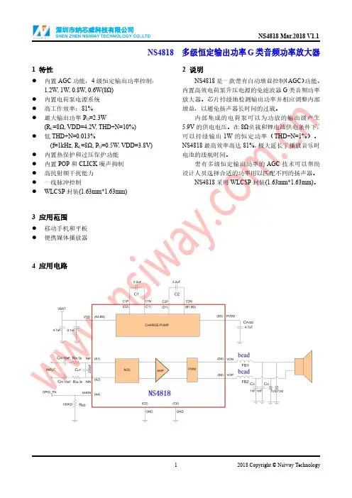
NS4818多级恒定输出功率G类音频功率放大器1特性●内置AGC功能,4级恒定输出功率控制:1.2W,1W,0.8W,0.6W(8Ω)●内置电荷泵电源系统●高工作效率:81%●最大输出功率P O=2.3W(R L=8Ω,VDD=4.2V,THD+N=10%)●低THD+N=0.013%(f=1kHz,R L=8Ω,P O=0.5W,VDD=3.8V)●内置热保护和过压保护功能●内置POP和CLICK噪声抑制●高抗射频干扰能力●一线脉冲控制●WLCSP封装(1.63mm*1.63mm)3应用范围●移动手机和平板●便携媒体播放器2说明NS4818是一款带有自动增益控制(AGC)功能、内置高效电荷泵升压电源的免滤波器G类音频功率放大器。
芯片持续地检测输出功率并相应调整内部增益,以避免扬声器长时间的过载。
内部集成的电荷泵可以为功放的输出级产生5.9V的供电电压。
在8Ω负载和锂电池供电条件下,可以持续输出1W的恒定功率(THD+N=1%)。
NS4818最高效率高达81%,极大延长了播放音乐时电池的续航时间。
带有多级恒定输出功率的AGC技术可以帮助设计人员选择合适的功率用以匹配不同的扬声器。
NS4818采用WLCSP封装(1.63mm*1.63mm)。
4应用电路5管脚配置NS4818WLCSP的俯视图如下图所示:NS4818管脚说明:管脚编号管脚名称管脚说明A1INP音频信号输入正端A2INN音频信号输入负端A3,B3VDD电源A4SHDN一线脉冲控制端B1,B2C2N电荷泵C2电容负端B4VOP音频放大器输出正端C1C1N电荷泵C1负端C2,C4GND地D1C2P电荷泵C2正端D2C1P电荷泵C1正端D3PVDD音频功放级电源D4VON音频放大器输出负端6极限工作参数参数最小最大单位供电电压范围VDD-0.3 5.2V输入电压范围INP.INN.SHDN-0.3VDD+0.3V工作温度范围-4085℃工作结温范围-40150℃储存温度范围-65150℃最小负载阻抗4ΩHBM ESD8000VMM ESD200VθJA15-ball WLCSP 1.63x1.63mm70℃/W注:如果器件工作条件超过上述极限值,可能对器件造成永久性损坏。
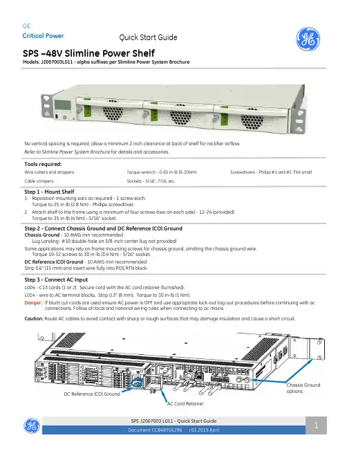
Document CC848916296r03 2015 AprilSPS J2007003 L011 - Quick Start Guide 1Tools required:Wire cutters and strippers Torque wrench - 0-65 in-lb (0-10Nm) Cable crimpersSockets - 5/16”, 7/16, etc.Screwdrivers - Philips #1 and #2, Flat smallNo vertical spacing is required, allow a minimum 2 inch clearance at back of shelf for rectifier airflow. Refer to Slimline Power System Brochurefor details and accessories.Quick Start GuideGECritical PowerSPS –48V Slimline Power ShelfModels: J2007003L011 - alpha suffixes per Slimline Power System BrochureAC Cord RetainerChassis Ground optionsDC Reference (CO) GroundStep 2 - Connect Chassis Ground and DC Reference (CO) GroundChassis Ground - 10 AWG min recommendedLug Landing: #10 double-hole on 5/8-inch center (lug not provided)Some applications may rely on frame mounting screws for chassis ground, omitting the chassis ground wire. Torque 10-32 screws to 30 in-lb (3.4 Nm) - 5/16” socket. DC Reference (CO) Ground - 10 AWG min recommended Strip 0.6” (15 mm) and insert wire fully into POS RTN block.Step 3 - Connect AC InputL004 - C13 cords (1 or 2). Secure cord with the AC cord retainer (furnished). L014 - wire to AC terminal blocks. Strip 0.3” (8 mm). Torque to 10 in-lb (1 Nm).Danger: If blunt cut cords are used ensure AC power is OFF and use appropriate lock-out tag-out procedures before continuing with acconnections. Follow all local and national wiring rules when connecting to ac mains. Caution: Route AC cables to avoid contact with sharp or rough surfaces that may damage insulation and cause a short circuit.Step 1 - Mount Shelf1. Reposition mounting ears as required - 1 screw each. Torque to 25 in-lb (2.8 Nm) - Phillips screwdriver.2. Attach shelf to the frame using a minimum of four screws (two on each side) - 12-24 (provided). Torque to 35 in-lb (4 Nm) - 5/16” socket.Document CC848916296r03 2015 AprilSPS J2007003 L011 - Quick Start Guide 2Step 4 - Connect DC Output and Battery, and DC Reference (CO) GroundUSB Craft PortJ2 Alarm inputsJ1 Alarm outputsJ3 1-Wire Battery Temp MonitorJ5 LAN PortStep 5 - Set Jumpers - LAN Port and Relay per Galaxy Pulsar Edge Controller Quick Start Guide Signal ConnectionsDC Outputs - GMT style fused (15A max fuses)Connect outputs and returns to the terminal blocks. 12 AWG max Strip 0.35” (9 mm) Torque to 4 in-lb (0.45 Nm)DC Aux Output - optionalConnect Aux output and return to the terminal blocks. 8 AWG max Strip 0.6” (15 mm) Insert wires fully into blockInsert small flat screwdriver to open clamp..BatteryConnect outputs and returns to the terminal blocks. 8 AWG max Strip 0.6” (15 mm) Insert wires fully into blockInsert small flat screwdriver to open clamp..CAUTION : Verify battery voltage and polarity with a voltmeterbefore proceeding.BatteryDC Outputs 1-6 GMT style fused15A max fusesDC Outputs 7-12 GMT style fusedDC Aux OutputDC Reference (CO) GroundConnectors are on rear.1. J1-2 Alarms and Inputs - Connect to office alarms and signals. See Information: Alarm Connections for Details2. J5 LAN - Connect to Ethernet network.Step 6 - Install Controller per Galaxy Pulsar Edge Controller Quick Start Guide Step 7 - Install Signal and Communications Cables1. Connect 1-Wire Battery Temp and Voltage Monitor to J3Step 8 - Install 1-Wire Battery Temp and Voltage Monitor per Galaxy Pulsar Edge Controller Quick Start Guide - OptionalFirmly push the rectifier into the rectifier slot.Tighten the thumb screw until the rectifier is seated.NOTE: When installing a rectifier in a powered system the RUN LED on the rectifier will blinkuntil communication with the controller is established.Step 9 - Install RectifiersStep 10 - Initial Start UpVerify that all AC, DC and Alarm connections are complete and secure. Turn on AC input breakers. If there are no alarms, make required adjustments to the default settings on the controller for this installation.Document CC848916296r03 2015 AprilSPS J2007003 L011 - Quick Start Guide 1Step 11 - Configure Controller per Galaxy Pulsar Edge Controller Quick Start GuideVerify and edit controller basic configuration parameters per site engineering instructions.Information: Rectifier Options1Output Current at 54.5V. Outputs are power limited, not current limited.Information: Alarm ConnectionsSee the Slimline Power System Brochure for details.Alarm connections are on the rear of the shelf - J1 is Alarm Outputs and J2 is Alarm Inputs. Change alarm descriptions via LAN port (Web pages) or Craft port (EasyView2) when required.Specifications and Application∙ Specifications and ordering information are in the Slimline Power System Brochure available at ∙ External Surge Protective Devices (SPDs) - are required on all AC inputs.Equipment Safety is Approved in IEC 60664-1 Installation Category II environments.∙ Equipment and subassembly ports: 1. are suitable for connection to intra-building or unexposed wiring or cabling;2. can be connected to shielded intra-building cabling grounded at both ends.∙ Grounding / Bonding Network – Connect to an Isolated Ground Plane (Isolated Bonding Network) or an Integrated Ground Plane(Mesh-Bonding Network or Common Bonding Network).∙ Installation Environment - Install in Network Telecommunication Facilities, OSP, or where NEC applies. ∙ Battery return may be either Isolated DC return (DC-I) or Common DC return (DC-C).Reference DocumentsThese documents are available at .Document Title850035894Galaxy Pulsar Edge Quick Start GuideCC848815341 Pulsar Edge Controller Family Product ManualSlimline Power System Brochure3SPS J2007003 L011 - Quick Start Guide2Precautions∙ Install, service, and operate equipment only by professional, skilled and qualified personnel who have the necessary knowledge andpractical experience with electrical equipment and who understand the hazards that can arise when working on this type of equipment.∙ Disconnect batteries from outputs and/or follow safety procedures while working on equipment. Batteries may be connected in parallel with the output of the rectifiers. Turning off the rectifiers will not necessarily remove power from the bus.∙ Do not disconnect permanent bonding connections unless all power inputs are disconnected.∙ Verify that equipment is properly safety earth grounded before connecting power. High leakage currents may be possible.∙ Exercise care and follow all safety warnings and practices when servicing this equipment. Hazardous energy and voltages are present inthe unit and on the interface cables that can shock or cause serious injury. When equipped with ringer modules, hazardous voltages will be present on the ringer output connectors.∙ Use the following precautions in addition to proper job training and safety procedures: ∙ Use only properly insulated tools.∙ Remove all metallic objects (key chains, glasses, rings, watches, or other jewelry).∙ Follow Lock Out Tag Out (LOTO) procedures: customer specified, site specific, or general as appropriate.Disconnect all power input before servicing the equipment. Check for multiple power inputs.∙ Wear safety glasses.∙ Follow Personal Protective Equipment requirements: customer specified, site specific, or general as appropriate. ∙ Test circuits before touching.∙ Be aware of potential hazards before servicing equipment.∙ Identify exposed hazardous electrical potentials on connectors, wiring, etc. ∙ Avoid contacting circuits when removing or replacing covers;.∙ Use a personal ESD strap when accessing or removing electronic components.∙ Personnel with electronic medical devices need to be aware that proximity to DC power and distribution systems, including batteries andcables, typically found in telecommunications utility rooms, can affect medical electronic devices, such as pacemakers. Effects decrease with distance.4 Safety Statements∙ ∙ Do not install this equipment over combustible surfaces.∙ ∙ Rules and Regulations - Follow all national and local rules and regulations when making field connections. ∙ ∙ Compression Connectors∙ ∙ U. S. or Canada installations - use Listed/Certified compression connectors to terminate Listed/Certified field-wire conductors.∙ ∙ All installations - apply the appropriate connector to the correct size conductor as specified by the connector manufacturer, using onlythe connector manufacturer’s recommended or approved tooling for that connector.∙ ∙ Electrical Connection Securing: Torque to the values specified on labels or in the product documentation. ∙ ∙ Cable Dress - dress to avoid damage to the conductors and undue stress on the connectors. ∙ ∙ Circuit Breakers and Fuses∙ ∙ Use only those specified in the equipment ordering guide.∙ ∙ Size as required by the National Electric Code (NEC) and/or local codes.Safety Tested Limits - Refer to the equipment ratings to assure current does not exceed: Continuous Load (List 1) - 60% of protector rating Maximum Load (List 2 - typically end of discharge) - 80% of protector rating.∙ ∙ GMT Style Fuses - Use only fuses provided with safety caps.∙ ∙ Field-wired Conductors - Follow all National Electric Code (NEC) and local rules and regulations. ∙ ∙ Insulation rating: 90°C minimum; 105°C (minimum) if internal to enclosed equipment cabinets.∙ ∙ Size AC field-wired conductors with 75°C ampacity (NEC) equal to or greater than their panel board circuit breaker rating. ∙ ∙ AC and DC input disconnect/protection - Provide accessible devices to remove input power in an emergency. ∙ ∙ Alarm Signals - Provide external current limiting protection. Rating 60V, 0.5A unless otherwise noted.∙ ∙ Grounding - Connect the equipment chassis directly to ground. In enclosed equipment cabinets connect to the cabinet AC service ground bus. In huts, vaults, and central offices connect to the system bonding network.。
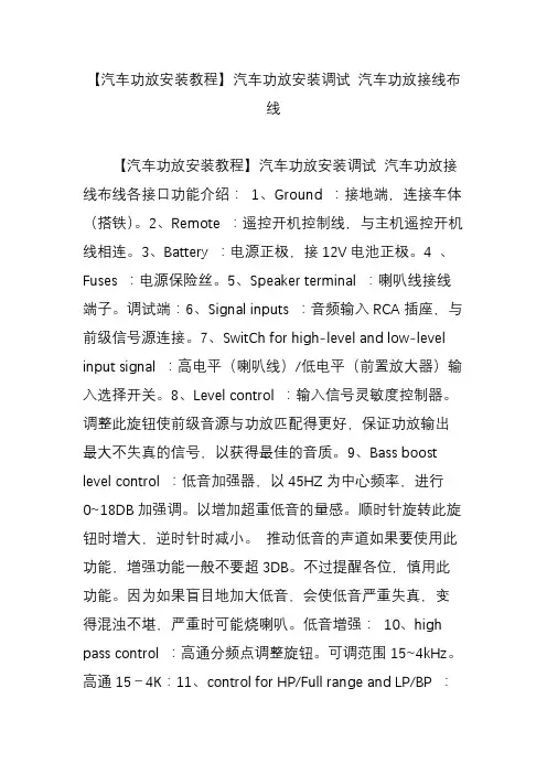
【汽车功放安装教程】汽车功放安装调试汽车功放接线布线【汽车功放安装教程】汽车功放安装调试汽车功放接线布线各接口功能介绍:1、Ground :接地端,连接车体(搭铁)。
2、Remote :遥控开机控制线,与主机遥控开机线相连。
3、Battery :电源正极,接12V电池正极。
4 、Fuses :电源保险丝。
5、Speaker terminal :喇叭线接线端子。
调试端:6、Signal inputs :音频输入RCA插座,与前级信号源连接。
7、SwitCh for high-level and low-level input signal :高电平(喇叭线)/低电平(前置放大器)输入选择开关。
8、Level control :输入信号灵敏度控制器。
调整此旋钮使前级音源与功放匹配得更好,保证功放输出最大不失真的信号,以获得最佳的音质。
9、Bass boost level control :低音加强器,以45HZ为中心频率,进行0~18DB加强调。
以增加超重低音的量感。
顺时针旋转此旋钮时增大,逆时针时减小。
推动低音的声道如果要使用此功能,增强功能一般不要超3DB。
不过提醒各位,慎用此功能。
因为如果盲目地加大低音,会使低音严重失真,变得混浊不堪,严重时可能烧喇叭。
低音增强:10、high pass control :高通分频点调整旋钮。
可调范围15~4kHz。
高通15-4K:11、control for HP/Full range and LP/BP :全通、低通/带通、高通滤波器选择开关。
全通时,全频带的音频信号将不做任何处理直接输送到后级电路。
低通/带通时,全频带的音频信号通过低通/带通波器后,再输送到后级电路。
通过旋钮10和12可以分别调整高通、低通的分频点,以适应相应的喇叭单元,获得最佳的音质。
高通时,全频带的音频信号通过高通波器后,再输送到后级电路。
通过旋钮10可调整高通分频点,以适应相应的喇叭单元,获得最佳的音质。
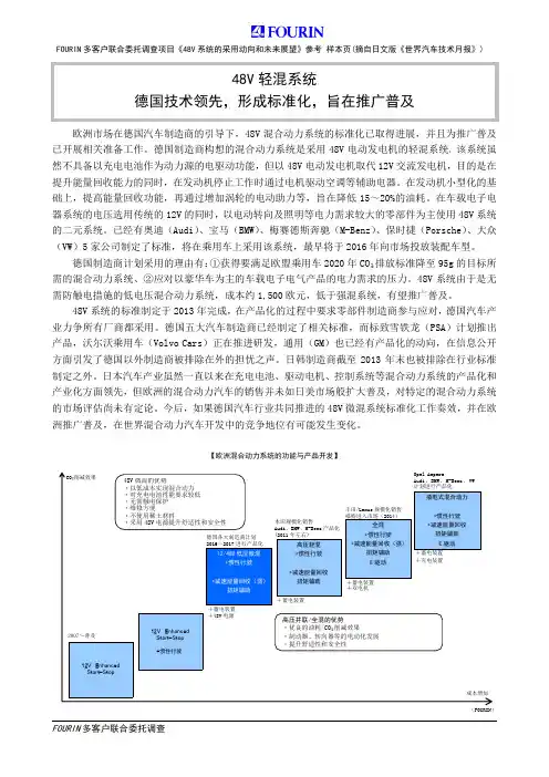
欧洲市场在德国汽车制造商的引导下,48V混合动力系统的标准化已取得进展,并且为推广普及已开展相关准备工作。
德国制造商构想的混合动力系统是采用48V电动发电机的轻混系统,该系统虽然不具备以充电电池作为动力源的电驱动功能,但以48V电动发电机取代12V交流发电机,目的是在提升能量回收能力的同时,在发动机停止工作时通过电机驱动空调等辅助电器。
在发动机小型化的基础上,提高能量回收功能,再通过增加涡轮的电动助力等,旨在降低15~20%的油耗。
在车载电子电器系统的电压选用传统的12V的同时,以电动转向及照明等电力需求较大的零部件为主使用48V系统的二元系统。
已经有奥迪(Audi)、宝马(BMW)、梅赛德斯奔驰(M-Benz)、保时捷(Porsche)、大众(VW)5家公司制定了标准,将在乘用车上采用该系统,最早将于2016年向市场投放装配车型。
德国制造商计划采用的理由有:①获得要满足欧盟乘用车2020年CO₂排放标准降至95g的目标所需的混合动力系统、②应对以豪华车为主的车载电子电气产品的电力需求的压力。
48V系统由于是无需防触电措施的低电压混合动力系统,成本约1,500欧元,低于强混系统,有望推广普及。
48V系统的标准制定于2013年完成,在产品化的过程中要求零部件制造商参与应对,德国汽车产业力争所有厂商都采用。
德国五大汽车制造商已经制定了相关标准,而标致雪铁龙(PSA)计划推出产品,沃尔沃乘用车(Volvo Cars)正在推进研发,通用(GM)也已经有产品化的动向,在信息公开方面引发了德国以外制造商被排除在外的担忧之声。
日韩制造商截至2013年末也被排除在行业标准制定之外。
日本汽车产业虽然一直以来在充电电池、驱动电机、控制系统等混合动力系统的产品化和产业化方面领先,但欧洲的混合动力汽车的销售并未如日美市场般扩大普及,对特定的混合动力系统的市场评估尚未有定论。
今后,如果德国汽车行业共同推进的48V微混系统标准化工作奏效,并在欧洲推广普及,在世界混合动力汽车开发中的竞争地位有可能发生变化。
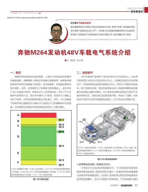
2020/07·汽车维修与保养57◆文/福建 林宇清奔驰M264发动机48V车载电气系统介绍一、概述随着科技的发展和生活的提高,人类对汽车舒适品质的要求也越来越高。
梅赛德斯-奔驰近年来通过按摩座椅、座椅加热器和电热杯座等功能增强了舒适性,但功能越多,对电能的需求也随之增加。
这样,在传统的12V车载电气系统基础上,成功开发了48V车载电气系统,其电压比12V系统高四倍,弥补了12V车载电气系统的不足,但它并未替代12V系统,而是在12V基础上进行了延伸,从而实现更高的输出功率(图1)。
另外,48V车载电气系统的电压直接定位为最大60V直流(DC)的接触保护法定限值,它无需高压车载电气系统的高安全性和个人保护措施。
二、组成部件48V车载电气系统除了首先应用在M256发动机上,还应用于新型四缸火花点火式发动机M264上,在装配发动机M264的情况下,采用皮带驱动启动机发电机(BSA),而非12V发电机和启动机。
除了发电机功能,其也可使用来自48V车载电网蓄电池的能量生成扭矩以辅助内燃机。
48V系统与内燃机的相互作用可产生更好的响应性,使发动机启动更快更平顺,并减少了油耗。
该系统由不同的48V部件和线路构成(图2),以下对此进行简要介绍。
M75/11.电动冷却液泵;F153/2.发动机舱48V 熔丝盒;N83/1.直流/直流转换器控制单元;G1.车载电网蓄电池;G1/3.48V 车载电网蓄电池;M1/10.启动机发电机。
图2 48V系统组成部件1.皮带驱动启动机-发电机(BSA)在有些M264发动机的电源版本中,12V的启动机和发电机被皮带驱动启动机-发电机所取代(图3),标准的皮带张紧器替换为回转皮带张紧器(图4)。
启动机-发电机通过刚性皮带轮集成在皮带驱动装置中,为48V车载电气系统发电,产生的电能可通过图1 48V电压范围A.60V 接触保护范围;B.58V 过压范围;C.52~54V 带功能性限值的较高工作范围;D.48V(36~52V)不带功能性限值的工作范围;E.36~24V 带功能性限值的较低工作范围;F.24~20V 低电压范围。

汽车音响怎么接线音响主机一般有:四组喇叭线、常电(B+)、ACC、地线;功放那里有:常电、功放控制线、四组音频输入和四组音频输出端口。
两个高音喇叭一定要同前门两个6寸扬声器并连接,白色线接前面右边喇叭,灰色线接前面左边喇叭。
索尼的CD不能直接推动低音炮,你那个低音炮里面有功放就可以加低频线到RAC接口,主机后面有的,跟家里的音响一样,你这个有功放的低音炮还要加电源线和控制线。
绿色线接右边后面的6*9喇叭,紫色线接后面6*9左边喇叭。
电源接口的接法是红+为正极常火.黄+为正极开关电源(接钥匙门).黑-为负极(接打铁).蓝+显示屏小背光电源(接小灯).棕色+电动天线控制电源线.还有很多车的线束都不一样,请说明种类要是汽车喇叭的话就比较简单,连接CD的线束有四组线是在一起的,其中白色和白黑是接汽车左前喇叭,棕色和棕黑是接右前喇叭,紫色和紫黑接左后喇叭,绿色和绿黑接接右后喇叭。
其实音响上面也是有接线图的,按照它的接法接就可以了。
如果自己实在搞不定,那自己比较好不要装,找个好点的店安装。
2汽车音响喇叭线的选择关于汽车音响喇叭线的选择,下面介绍了几种1、单晶铜喇叭线只合适低音音频的频率越低,信号的传输越接近导体的中心,单晶铜就是一个非常有利于中心传输的材料,在高档的音响改装中可以合计这样的材料,因为喇叭线不像电源线必须要非常多的导体材料,所以值得合计。
2、中音喇叭单个导体规格建议在0.10-0.15之间这个也是和传输频率的凹凸有关系,因为中音的频率不算高也不算低,所以导体规格也不必须要太粗也不必须要太细。
3、高喇叭单个导体规格建议在0.10以下,越细越好。
高音的频率比较高,信号的传输越接近导体的表面,所以同样的平方数我们通过增加条数来就可以增加导体的表面积,以达到高频的传输效果。
4、镀银喇叭线只合适高音同样的道理,因为银的传输速度快,所以在高频传输能起到很好的作用,但银有发热快的特点,生产过程必须要特别绝缘材料和工艺制定才干达到很好的效果,所以如果生产不当效果反而还不如很一般喇叭线。
基于半桥电路的48V/3A电动自行车充电器设计摘要在如今这个提倡绿色可持续发展的社会,因为电动自行车的广泛应用,其充电器的市场也越来越大,性价比高的电动车充电器在这个大舞台上,是很有竞争力的。
所以我们根据半桥电路的特点设计了一个48V/3A的电动自行车充电器。
这个充电器是根据电流模式的开关电源原理而设计的,其主电路采用了半桥电路,控制电路以SG3525芯片为核心,驱动电路使用IR2104为核心,结合稳压器等芯片,实现了对蓄电池的充电和控制,以达到在充电时对蓄电池进行保护的目的。
本设计中介绍了使用到的相关的芯片,而且给出了完整的电路图,具体地分析了主电路的工作原理、各部分电路的工作原理和各种相关芯片的介绍,这其中包括了主电路、控制电路、驱动电路和电压、电流反馈电路的工作原理。
并且还使用了MATLAB进行仿真,结果表明,该电动车充电器性能优良,能较好的保护蓄电池,稳定性非常强,而且成本比较低,非常有前景。
关键词:半桥电路,SG3525,电流模式,充电器DESIGN OF 48V/3A ELECTRIC BICYCLE CHARGERBASED ON HALF BRIDGE CIRCUIT FOR 48V/3AELECTEIC BICYCLE CHARGER BASED ON HALFBRIDGE CIRCUITABSTRACTIn this advocate green and sustainable development of the society, because of the widespread use of electric bicycle charger, the market is more and more big, high performance electric car charger in this big stage, is very competitive. So we design a 48V/3A electric bicycle charger based on half bridge circuit. This charger is designed according to the principle of the current mode switching power supply, the main circuit adopts half bridge circuit, the control circuit based on SG3525 chip as the core, drive circuit using IR2104 as the core, combined with the regulator chip, realizes the charging and control of the battery, in order to protect the battery during charging to. This design describes the use of related chips, and presents the design of integrated circuit, a detailed analysis of the working principle and circuit design, each part of the circuit chip is introduced, including the working principle of the main circuit, control circuit, drive circuit and voltage and current feedback circuit. The simulation results show that the charger has good performance and can protect the storage battery better. The stability of the MATLAB charger is very strong, and the cost is low. It is very promising.KEYWARDS:The half bridge circuit, SG3525, current mode ,charger目录1绪论 (5)1.1 研究背景 (5)1.2 研究现状 (5)1.3 充电器的结构与分类 (6)1.3.1 充电器的分类 (6)1.3.2 充电器的结构 (7)1.4 本文设计内容及要求 (7)1.4.1设计内容 (7)1.4.2设计要求 (7)2电动车自行车蓄电池及其充电方式介绍 (9)2.1 电动车的蓄电池 (9)2.2 电动车蓄电池充电方式 (9)2.2.1 恒流充电 (9)2.2.2 恒压充电 (10)2.2.3 浮充法 (11)2.2.4 涓流充电 (11)2.3 分阶段充电法 (12)3芯片和电路原理介绍 (14)3.1芯片介绍 (14)3.1.1 SG3525芯片 (14)3.1.2 IR2104芯片 (16)3.1.3 TL341芯片 (17)3.2电路原理介绍 (20)3.2.1主电路电路原理 (20)3.2.2 整流电路 (21)3.2.3 滤波电路 (23)3.2.4 半桥电路 (24)3.2.5 半桥电路的驱动电路 (25)3.2.6电压反馈电路 (26)3.2.7 电流反馈电路 (27)3.2.8辅助供电电路 (28)4变压器的选择和元器件参数计算 (29)4.1变压器的设计 (29)4.2 输出滤波电感选择 (31)4.3 SG3525确定频率的电容和电阻参数计算 (31)4.4 SG3525的软启动电阻说明 (32)4.5 输入输出滤波电容选择 (32)4.5.1输入滤波电容选择 (32)4.5.2输出滤波电容选择 (32)4.6 一次侧整流二极管的选择 (32)4.7 开关管、续流二级管和二次侧整流二极管的选择 (32)5 MATLAB仿真 (34)6结论 (37)致谢 (38)1绪论1.1 研究背景随着工业产业的发展,我们生活的环境正在一天天的变坏,而造成这样后果的原因,就是大气被严重污染。
大功率工业直流开关电源型号:TTC2.4K 48V50A可调稳压恒流电源使用说明书感谢您选购本公司产品,我们将会给您提供优异的产品质量保障,竭诚为您服务好每台电源的售后!本机型最大输出功率:2400W,最高输出电压48V,最大输出电流:50A具有交、直流兼容输入、输入输出全隔离应用开关电源技术和无主均流法,体积小、效率高、重量轻,可多台机并联扩流。
主要特点●该电源广泛应用于工控设备、电镀电解、污水处理、电力直流屏系统、通信、科研、蓄电池充电等设备。
●采用无工频变压器的开关电源电路,具有交、直流兼容输入,体积小、重量轻、效率高。
●开关电源控制芯片采用进口军用级IC,功率逆变管采用进口快速IGBT模块,其余元件则采用进口工业等级器件,电路设计优化合理,生产工艺严格完善,保证机器的可靠性和稳定性;●输入电压范围宽,输入输出全隔离。
●作为稳压电源使用时,当负载电流<电流设定值时,本电源的输出电压稳定在所设定值,输出电流随负载的实际电流变化。
●作为恒流电源使用时,当负载电流>电流设定值时,本电源的输出电流恒定在所设定值,输出电压随负载的实际大小而变化。
●并机扩流功能,采用输出并联无主均流法,所谓无主均流法------无需由一个主控单元对各个电源模块进行控制,即参与并联的各个电源模块的输出电流的份额是平等的,若其中一个因故退出,不会影响负载的正常工作,免去了像由一个主控单元控制那样,再重新设置的麻烦。
无主均流的使用简单,每个电源模块输出由2条均流母线,只需将参与并联的各个电源模块的均流母线并联连接就行。
操作方法如下:●完善的保护功能:输入过流、过压、欠压保护;输出短路,过流,过压保护;开机延时软启动,避免输出电压过冲;整机过热关机保护。
●智能温控风扇散热,延长风扇的使用寿命。
●面板设有2个数显表,独立显示输出电压和输出电流,。
●面板设有2个电位器分别调节输出电压和输出电流,使用方便。
工作原理简述交流输入电压经“输入陷波”电路后到“整流滤波”电路,得到高压(约300V)直流电压。
我的旅行床车(48V)方案分享一、用电思路:两组车载220V电源,大功率逆变器48V3000W(预留1000W功率,避免过热),使用功率2000W,使用微波炉、电压力锅、开水壶等常规电器,以备大风等恶劣环境下使用;小功率逆变器12V600W,主要用于对小容量电瓶充电和日常小功率用电,比如手机、对讲机充电,电脑用电等。
逆变器:组装的工频逆变器。
电瓶选择:使用的是48V共四个副电瓶,大电瓶使用12V 300Ah,三个小容量电瓶12V100Ah。
12V大电瓶为车载冰箱供电和驻车时对小逆变器供电,48V为大功率逆变器供电。
充电方式:大电瓶采用同口方式充电,小电瓶用小逆变器(12V600W)的220V充电器充电。
导线选择:副电瓶之间的连线和与大功率逆变器的连接线都使用16平方(60A)的铜线。
起动电瓶与副电瓶的连接线用10平方(40A)的铜线,双电瓶管理器与副电瓶的连接线用10平方(40A)的铜线,与小功率逆变器的连线采用10平方(40A)的铜线。
电路设计:1、大功率逆变器只采用48V供电,小功率逆变器在汽车启动后用发动机供电,驻车后用12V大副电瓶供电。
2、大副电瓶充电管理电路采用过欠压控制电路、延时电路和继电器组成。
3、电路原理图:原理简介:汽车启动后,过欠压控制器通电,(设置为低于13.5V保护,这样,当启动电瓶的电压低于这个值时,不输出电压,这个一般是熄火后),电压高于13.5V后,输出电压进入下一级延时控制器,经约25s延时,输出电压接通继电器J1,J1常开端闭合,启动电瓶的12V电压通过J2的常闭触头与副电瓶接通,给副电瓶同口充电。
如果此时接通小功率逆变器开关,J2吸合,J2的常开触头接通(与副电瓶断开),发动机供电小逆变器,供行车时的充电和对小容量副电瓶充电(此时J1和J3是同时接通的,J3的常开端闭合,可以对小容量副电瓶供电)。
如果汽车熄火,则点烟器接口断电,此时J1和J3都断开,常闭端接通,主电瓶与副电瓶是断开的,不对副电瓶充电。
SAE Audio renowned Regulated SMPS power supply unit.High efficiency Class I™ power modules.Highly sensitive CMRR balanced inputs for improved noise rejection.Top electronic elements for a superior sonic quality.Maximum stability even with continuous full-power on 2Ω loads.XLR input and signal link connectors.SpeakON NL4 and binding post output connectors.Input sensitivity selector on the back panel (26dB / 28dB / 32dB / 1.4v / 1v / 0.775v).Routing mode selector on the back panel (stereo / bridge-parallel).Channel independent temperature, protection, VHF and clip warning indicators on the front panel.Channel independent -5dB/-10dB/-15dB/-20dB/signal presence and mute indicators on the front panel.Power and bridge/parallel indicators on the front panel. Low unit weight (16kg on the highest power model PQM13).Class I™SAE Audio patented Class I™ is the most advanced technology on high power audio amplification. The output signal amplified through a Class I™ power module accurately tracks the input signal waveform, achieving a much greater efficiency and sonic quality than on other standard amplifier classes. Class I™ amplification is capable to deliver extremely high power density with an unprecedented audio fidelity.R-SMPSToo often, on several sound reinforcement applications, mains voltage fluctuations due to poorly designed power distribution networks or non-stable power generators are an inconvenient for sound reinforcement equipment performance. In the case of amplifiers it causes undesired output sound level variations according to the mains input power. The PQM series of power amplifiers feature a Regulated Switching Mode Power Supply to keep a stable output signal level disregarding the mains stability. With the R-SMPS power supply a good sound performance is guaranteed even with the less convenient power conditions.TechnologyMid and big world-class pro-touring applications.Mid and big sized clubs and installations with high power density requirements.Multi-way speakers power amplification.Line array and big sized systems power amplification.Professional rental industry.HS-CMRR Balanced InputsThe best signal quality at an amplifier output can only be achieved with the best signal quality at its input. With the PQM series is not a problem to have long signal input cables along with power lines or other induced noise sources. The balanced signal inputs on the PQM amplifiers implement a High Sensitivity CMRR (Common Mode Rejection Ratio) design in order to reject even the slightest added distortion on the signal, thus assuring the best possible audio signal at the input.Top Electronic ElementsBeing the 4-channel SMPS flagship series of SAE Audio power amplifiers the PQM series solely mount the best premium quality audio-specific electronic elements with the highest proven durability available on the market. Any sound performance influential parts inside the PQM amplifiers, including the operational amplifiers, power supply capacitors or power module bipolar junction transistors, are thoroughly selected among the best available audio-specific components in order to reach the best possible audio quality.PQM seriesPQM rear panel20Hz - 20kHz,+0/-1.5dB≥ 80dB ≤ 0.05%≥ 80040.3dB42.3dB0.775v / 1v / 1.4v / 38dB / 32dB / 26dB 20kΩ / 10kΩAir flow from front to rear595 x 565 x 170483 x 451 x 8915.5kg15.7kg2100W x42500W x44200W x21400W x41600W x42800W x23200W x25000W x2SAE reserves the right to make any changes to the product specifications without prior notice. Final specifications to be found in the user manual.*Power tested under the condition of 40ms burst, 1KHz sine wave and 1% THD. **Power tested under the condition of 20ms burst, 1KHz sine wave and 1% THD.4Ω Stereo**2Ω Stereo**8Ω Bridge**4Ω Bridge**No. 39 WenJiao Road East, HeShun, NanHai, FoShan, GD, China.TEL: +86 - 757 - 8512 - 9007FAX: +86 - 757 - 8568 - 8191Dimension (mm)Other specificationS/N rateFrequency response THD+N Damping factor Input sensitivityInput impedance (bal/unbal)Voltage gain CoolingDimension / Weight G.W.Product dimensions (mm)Packing dimensions (mm)Specifications。