功放电路图.ppt
- 格式:ppt
- 大小:495.01 KB
- 文档页数:15


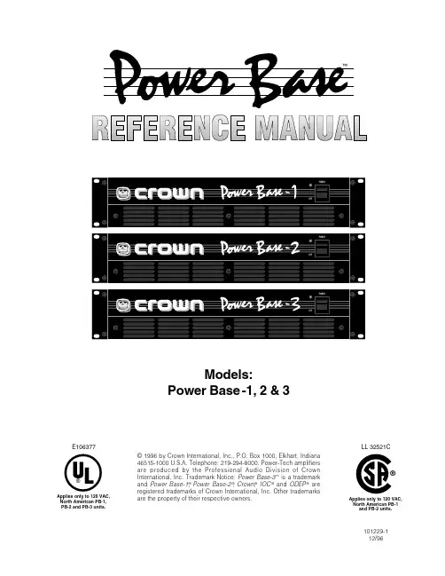
Models:Power Base-1, 2 & 3© 1996 by Crown International, Inc., P.O. Box 1000, Elkhart, Indiana46515-1000 U.S.A. Telephone: 219-294-8000. Power-Tech amplifiersare produced by the Professional Audio Division of CrownInternational, Inc. Trademark Notice: Power Base-3™ is a trademarkand Power Base-1®, Power Base-2®, Crown,®IOC® and ODEP® areregistered trademarks of Crown International, Inc. Other trademarksare the property of their respective owners.®E106377Applies only to 120 VAC,North American PB-1,PB-2 and PB-3 units.101229-112/96Applies only to 120 VAC,North American PB-1and PB-2 units.®LL 32521CThe lightning bolt triangle is used to alert the user to the risk of electric shock.The exclamation pointtriangle is used to alert the user to important operatingor maintenance instructions.The information furnished in this manual does not include all of the details of design, production, or variations of the equipment. Nor does it cover every possible situation which may arise during installation, operation or mainte-nance. If you need special assistance beyond the scope of this manual, please contact our T echnical Support Group.Crown Audio Division Technical Support GroupPlant 2 SW, 1718 W. Mishawaka Rd., Elkhart, Indiana 46517 U.S.A.Phone: 800-342-6939 (North America, Puerto Rico and Virgin Islands) or 219-294-8200Fax: 219-294-8301 Fax Back: 800-294-4094 (North America only) or 219-293-9200Internet: Power Base Series Power AmplifiersPage 41Welcome 71.1Unpacking 71.2Features 72Installation 92.1Stereo 92.2Mono 92.3102.4.......................................102.5103Operation 113.1113.2113.3113.3.1ODEP 113.3.2113.3.3Drive Protection 113.3.4.....................123.3.5123.4Controls 123.5124135Accessories 195.1195.2MT-BB 196Service 206.1Worldwide Service 206.2206.2.1206.2.220Power Base Series Power AmplifiersPage 51.17.......................................892.3Power Base Input Wiring 92.4Input Sensitivity Switch 1010121516161718185.1The MT-XLR 1919Power Base Series Power AmplifiersPage 7Power Base ODEP ®)MT-BB ac-Power PowerPower Base Series Power AmplifiersPage 8Power Base Series Power AmplifiersPage 92 InstallationAlways remove power from the unit and turn the level controls off (fully counterclockwise) when making or breaking connections. This reduces the chance of blasts that can cause loudspeaker damage.The guidelines below are provided to help you quickly get your amplifier installed and ready to go. Be sure to follow the instructions in Sections 2.1 and 2.2 for the selected mode of operation. Additional information on input sensitivity, load protection and required AC mains is provided in Sections 2.3, 2.4 and 2.5.1.Install the amplifier in a standard 19 inch (48.3 cm) rack or place it on a stable surface. The mounting dimensions are 19 inches (48.3 cm) wide, 3.5 inches (8.9 cm) tall and 16 inches (40.6 cm) deep behind the mounting sur-face. IMPORTANT! Allow for adequate ventilation.2.1 Stereo1.Turn down the level controls (fully counterclockwise) and turn off the amplifier.2.Set the back panel stereo/mono switch to Stereo.3.If present, remove the Parallel-Mono jumper.4.Connect the input and output cables as shown in the first example in Figure 2.1.5.Turn on the amplifier and adjust the level for each chan-nel using the back panel level controls.CAUTION: Never parallel the two outputs by di-rectly tying them together, and never parallel them with the output of another amplifier.2.2 MonoYour amplifier’s mono modes provide double the power of Stereo mode in a single channel. In Bridge-Mono mode, the outputs are wired in series for twice the output voltage. In Parallel-Mono mode, the outputs are paralleled for twice the current capacity.Bridge-Mono mode is provided for loads with an im-pedance greater than 4 ohms. Parallel-Mono mode should be used with loads of 4 ohms or less.B R I D G E - M O N O1.Turn down the level controls (fully counterclockwise) and turn off the amplifier.2.Set the back panel stereo/mono switch to Bridge-Mono.3.If present, remove the Parallel-Mono jumper.4.Connect the input and output cables as shown in the sec-ond example in Figure 2.1. Only use the channel 1 input.5.Make sure the load is balanced (neither side shorted to ground) and do not use the black (–) binding posts.6.Turn on the amplifier and adjust the level. Only use thechannel 1 level control.P A R A L L E L - M O N O1.Turn down the level controls (fully counterclockwise) and turn off the amplifier.2.Set the back panel stereo/mono switch to Parallel-Mono.3.Install a solid, 14-gauge (2 mm 2) or heavier jumper wire across the two red (+) binding post outputs.4.Connect the input and output cables as shown in the third example in Figure 2.1. Only use the channel 1 input.5.Turn on the amplifier and adjust the level. Only use the channel 1 level control.CAUTION: With Parallel-Mono wiring, do not switch to Stereo or Bridge-Mono mode until the output jumper wire is removed.AIR FLOWFig. 2.3 Power Base Input Wiringe high-quality loudspeaker cables to connect the load to the amplifier’s outputs. Do not use shielded cable.e shielded cables to connect audio sources to the amplifier inputs. Either balanced or unbalanced wiring can be used as shown below. (XLR connectors are avail-able with the MT-XLR accessory. See Section 5.)Fig. 2.2 Do NOT Block Air FlowPower Base Series Power AmplifiersPage 10Page 113.3.1 ODEPCrown invented ODEP to keep the amplifier working under demanding conditions and to increase output efficiency. To do this, Crown established a rigorous pro-gram to measure each transistor’s safe operating area (SOA). Intelligent circuitry was then designed to simu-late the instantaneous conditions of the output transis-tors. Its name describes what it does: Output Device Emulation Protection, or ODEP . In simple terms, ODEP compares transistor conditions to their known SOA. If more power will be asked of them than they can deliver under the existing conditions, ODEP limits the drive until conditions fall within the SOA. Limiting is propor-tional and kept to an absolute minimum—only what is required to prevent output transistor damage. Under normal conditions, no limiting is required and ODEP is transparent to the audio signal.ODEP makes possible a quantum leap in output effi-ciency and reliability—with ODEP , the show goes on.3.3.2 Ultrasonic and Radio Frequency ProtectionAn amplifier’s slew rate only needs to be large enough to deliver the maximum voltage at the highest required frequency. Higher slew rates actually allow undesirable ultrasonic and radio frequencies to be reproduced. By design, Power Base amplifiers have a controlled slew rate to limit the highest frequencies that they reproduce.Limiting occurs well above 20 kHz so there is no au-dible effect on performance. This approach protects the amplifier from radio frequencies and can even pro-tect some sensitive loads (including some tweeters).3.3.3 Drive ProtectionThe drive protection system temporarily removes output drive to protect the amplifier and its loads. Drive protec-tion can be activated in two situations. First, if dangerous subsonic frequencies or direct current (DC) is detected in the amplifier’s output, the unit will activate its DC/low-frequency protection circuitry which puts the amplifier in drive protection mode. This protects the loads and pre-vents oscillations. The unit resumes normal operation as soon as the amplifier no longer detects dangerous out-put. Although it is extremely unlikely that you will ever activate the amplifier’s DC/low frequency protection system, improper source materials like subsonic square waves or input overloads that excessively clip the input signal can activate this system.The amplifier’s fault protection system will put the am-plifier in drive protection mode in rare situations whereheavy common-mode current is detected in the output.3 Operation3.1 PrecautionsAlthough your amplifier is protected from external faults,the following safety precautions are recommended:1.There are important differences among the Stereo,Bridge-Mono and Parallel-Mono operating modes.Please refer to Sections 2 for additional information.2.WARNI NG: Do not change the position of the stereo/mono switch unless the amplifier is first turned off.3.CAUTI ON: I n Parallel-Mono mode, a jumper is used to connect the red binding post outputs.Be sure to remove this jumper for Bridge-Mono or Stereo mode, or high distortion and excessive heating will occur. Also, make sure the stereo/mono switch is set to the proper e care when making connections, selecting sig-nal sources and controlling the output level. The load you save may be your own!5.Do not short the ground lead of an output cable to the input signal ground. This will form a ground loop and may cause oscillations.6.Operate the amplifier from AC mains of not more than 10% variation above or below the selected line voltage and only at the specified line frequency.7.Never connect the output to a power supply out-put, battery or power main. Such connections may result in electrical shock.8.Tampering with the circuitry by unqualified person-nel or making unauthorized circuit changes may be hazardous and invalidates all agency listings.Remember: Crown is not liable for any damage that re-sults from overdriving other system components.3.2 Power IndicatorWhen lit, the amber power indicator (to the left of the power switch) shows that the amplifier has been turned on. It is driven only by the low-voltage power supply and does not indicate the status of the high-voltage supplies.3.3 Protection SystemsPower Base amplifiers have extensive protection sys-tems, including ODEP , ultrasonic/RF protection, drive protection, transformer thermal protection and fuses or circuit breakers that protect the power supplies.The unit should never output heavy common-mode cur-rent unless its circuitry is damaged. Activating drive protection helps prevent further damage.3.3.4 Transformer Thermal ProtectionAll Power Base amplifiers have transformer thermal protection. This protection circuitry is activated in un-usual situations where the unit’s transformer tempera-ture rises to unsafe levels. Under these abnormal conditions, the unit removes power to the high-voltage transformer. The fan will continue to run in all units ex-cept those with 220/240 VAC transformers. The ampli-fier will return to normal after it cools to a safe temperature.It is very unlikely that your Power Base amplifier will ever activate transformer thermal protection as long as it is operated within rated conditions. Your amplifier is designed to continue operating under conditions where other amplifiers would fail. But even when you exceed the limits of a Power Base amplifier, it still pro-tects itself—and your investment—from damage.3.3.5 Fuses and Circuit BreakersAll 120 VAC, 60 Hz units and all Power Base-3 units have a fuse that protects the low-voltage power supply and cooling fan. The Power Base-1 and Power Base-2 high-voltage power supplies are protected by fuses, while the Power Base-3 high-voltage power supplies are protected by a circuit breaker. With rated loads and output levels, these fuses (or the circuit breaker) should only shut down the amplifier in the incredibly rare instance of a catastrophic amplifier failure. The ODEP protection system keeps the amplifier opera-tional under most other severe conditions. The fuses (or breaker) can also shut down the amplifier in situa-tions where extremely low-impedance loads and high output levels result in excessive current draw.A Power Base amplifier will not blow its fuses or trip its breaker unless something is wrong. In the rare event that an internal fuse blows, please refer the unit to a qualified technician. If the breaker in a Power Base-3 trips, try to identify and correct the problem before re-setting it with the back panel Circuit Breaker Reset. If the problem persists, refer the unit to a qualified techni-cian.3.4 ControlsThe Power switch is th only control located on the front panel. All others are located on the rear, including the level controls.When making any setup or wiring changes, don’t forget to turn off the amplifier, turn down the level controls and disconnect the power cord. Be sure to turn down (full counterclockwise) the channel 2 level control when us-ing either mono mode. The Parallell Mono/Stereo/ Bridge Mono switch is used to select Stereo, Bridge-Mono or Parallel-Mono operating modes. The Input Ground Lift switch isolates the phone jack input grounds from the chassis ground to help prevent ground loops. It does not affect any installed input ac-cessories. The Input Sensitivity Switch, located inside the back cover plate, sets the amplifier’s input sensitiv-ity (refer to subsection 2.3 for information on changing this switch). And the Power Base-3 has a back panel Circuit Breaker Reset button that resets the circuit breaker (refer to subsection 3.3.5).CHANNEL 2CHANNEL 13.5 Filter CleaningA dust filter is provided on the unit’s air intake. If it be-comes clogged, the unit will cool less efficiently and may produce lower output levels. To clean the filter, use a phillips screwdriver to remove the three screws the secure the front grille. Use mild dishwashing deter-gent and warm water for best cleaning results. Be sure the filter is dry before you reinstall it. Replacement fil-ters may be ordered from the factory.Dust filters are not 100% efficient—long term this may require internal heat-sink cleaning by a qualified tech-nician. Internal cleaning information is available from our Technical Support Group.Fig. 3.1 Back Panel Level ControlsPage 124 Specificationsand an input sensitivity of 26 dB unless otherwise specified. Standard 1 kHz Power:watts at 1 kHz with 0.1% THD+noise.Full Bandwidth Power:watts from 20 Hz to 20 kHz with 0.1% THD+noise.120 VAC, 60 Hz Units:formers for 120 VAC, 60 Hz power mains.PerformanceFrequency Response:at 1 watt.Phase Response:at 1 watt.Signal-to-Noise:bandwidth power from 20 Hz to 20 kHz.Total Harmonic Distortion (THD):ing linearly to 0.1% at 20 kHz.Intermodulation Distortion (IMD):bandwidth power.Damping Factor:CrosstalkPower Base-1: Greater than 75 dB below full band-greater than 60 dB at 20 kHz.Power Base-2: Greater than 90 dB below full band-greater than 66 dB at 20 kHz.Power Base-3: Greater than 90 dB below full band-greater than 70 dB at 20 kHz.Common Mode Rejection (CMR):falling linearly to better than 50 dB at 20 kHz.Controlled Slew Rate: Greater than 13 volts/ms.Voltage Gain:dB position).Power Base-1: 51:1 ±12% or 34.3 dB ±1 dB at 0.775 sensitivity.Power Base-2: 64:1 ±12% or 36.2 dB ±1 dB at 0.775 volt sensitivity; 35:1 ±12% or 31.0 dB ±1 dB at 1.4 volt sensitivity.Power Base-3: 83:1 ±12% or 38.4 dB ±1 dB at 0.775 volt sensitivity; 46:1 ±12% or 33.3 dB ±1 dB at 1.4 volt sensitivity.The following specifications are guaran-Power Base-1Stereo mode (both channels driven):240watts into 4 ohms.200watts into 8 ohms.Bridge-Mono mode:455watts into 8 ohms.395watts into 16 ohms.Parallel-Mono mode:455watts into 2 ohms.400watts into 4 ohms.Power Base-2Stereo mode (both channels driven):460watts into 4 ohms.325watts into 8 ohms.Bridge-Mono mode:910watts into 8 ohms.660watts into 16 ohms.Parallel-Mono mode:920watts into 2 ohms.655watts into 4 ohms.Power Base-3Stereo mode (both channels driven):760watts into 4 ohms.540watts into 8 ohms.Bridge-Mono mode:1525watts into 8 ohms.1090watts into 16 ohms.Parallel-Mono mode:1530watts into 2 ohms.1080watts into 4 ohms.Safe with all types of loads. RatedPage 13Required AC Mains: Current, frequency and voltage requirements are provided on each unit’s back panel. All models draw 90 watts or less at idle.Power Base-1: Draws up to 6 amps of current.Power Base-2: Draws up to 10 amps of current.Power Base-3: Draws up to 15 amps of current.Low-Voltage Power Supply: A ±24 VDC fanformer supply (fan motor winding) regulated to ±15 VDC.AC Connector: An appropriate AC line cord and plug are provided. 120 VAC, 60 Hz units have a standard 3-wire, 15-amp grounded connector (NEMA 5-15P). ControlsPower: A front panel rocker switch used to turn the amplifier on and off.Level: A back panel rotary potentiometer for each chan-nel used to control the output level.Stereo/Mono: A three-position back panel switch used to select Stereo, Bridge-Mono or Parallel-Mono mode.Sensitivity: A three-position switch inside the back cover plate used to select the input sensitivity for both channels: 0.775 volts or 1.4 volts for standard 1 kHz power, or 26 dB voltage gain (see Section 2.3).Input Ground Lift: A two-position back panel switch used to isolate the phone jack and chassis grounds. Reset (Power Base-3 only): A back panel push but-ton used to reset the circuit breaker that protects the power supplies.IndicatorsPower: This amber indicator shows the on/off status of the low voltage power supply.Input/OutputInput Connector: Balanced ¼ inch phone jacks. See Section 5 for XLR and barrier block accessories.I nput I mpedance: Nominally 20 K ohms, balanced;10 K ohms, unbalanced.Output C onnector:T wo s ets o f c olor-coded 5-way b binding posts (for banana plugs, spade lugs or bare wire). Output Impedance: Less than 10 milliohms in series with less than 2 microhenries.DC Output Offset:Less than 10 millivolts.Output SignalStereo: Unbalanced, two-channel.Bridge-Mono: Balanced, single-channel. Channel 1 controls are active; Channel 2 controls should be turned down and not used.Parallel-Mono: Unbalanced, single-channel. Channel 1 controls are active; Channel 2 controls should be turned down and not used.ProtectionPower Base amplifiers are protected against shorted, open or mismatched loads; overloaded power supplies; excessive temperature, chain destruction phenomena, input overload and high-frequency blowups. They also protect loudspeakers from input and output DC, as well as providing protection from turn-on/turn-off transients.If operating conditions are unreasonable, the patented ODEP circuitry proportionally limits the drive level to pro-tect the output transistors, particularly in the case of el-evated temperature. A thermal switch imbedded in the transformer protects the power supplies from overload. In the rare event that a transformer overheats, the ther-mal switch removes power, waits until the unit has cooled to a safe temperature and then resets itself.Turn On: Four second delay with no dangerous tran-sients. Contact us if you need to change the delay. ConstructionDurable black finish on steel chassis with special “flow-through” ventilation from front to side panels.Cooling: Internal heat sinks with forced-air cooling for rapid, uniform heat dissipation.Dimensions: Standard 19-inch (48.3 cm) rack mount width (EIA RS-310-B), 3.5-inch (8.9 cm) height and 16-inch (40.6 cm) depth behind the mounting surface. Approximate Weight: Center of gravity is 6 inches (15.2 cm) behind front mounting surface.120 VAC, 60 Hz Units:Power Base-1: 30 pounds (13.6 kg) net; 34 pounds(15.4 kg) shipping weight.Power Base-2: 34 pounds (15.4 kg) net; 38 pounds(17.2 kg) shipping weight.Power Base-3: 36 pounds (16.3 kg) net; 40 pounds(18.2 kg) shipping weight.Page 14” Each ofguaranteed to meet or exceed their specifications for three years. Further, because our published specs are set below our “in-house” measurements, you can expect everyPage 15Page 16Page 17Page 185 AccessoriesThere are two accessories available at the time of this printing: the MT-XLR and the MT-BB. Important: The MT-XLR and MT-BB must be installed at a Crown Factory Service Center or the Crown factory.5.1 MT-XLRThe MT-XLR is an accessory panel that provides two standard 3-pin female XLR input connectors. The MT-XLR accessory makes it easy to quickly change connections in a system that uses standard XLR con-nectors. It can also be used in systems that need to daisy chain an input signal from one amplifier to an-other. Because the MT-XLR connectors are wired in parallel with the amplifier’s built in phone jack connec-tors, an input signal fed to either input can be fed to another amplifier from the unused connector for that channel.5.2 MT-BBThe MT-BB is an accessory panel that provides barrier strip input connectors. An MT-BB accessory might be desirable in applications requiring bare wire connec-tions. It can also be used to daisy chain an input signal from one amplifier to another just like the MT-XLR.Fig. 5.1 The MT-XLRFig. 5.2 The MT-BBPage 196 ServiceThis unit has very sophisticated circuitry which should only be serviced by a fully trained technician. This is one reason why each unit bears the following label: CAUTI ON: To prevent electric shock, do not re-move covers. No user serviceable parts inside. Re-fer servicing to a qualified technician.6.1 Worldwide ServiceService may be obtained from an authorized service center. (Contact your local Crown/Amcron representa-tive or our office for a list of authorized service centers.) To obtain service, simply present the bill of sale as proof of purchase along with the defective unit to an authorized service center. They will handle the neces-sary paperwork and repair.Remember to transport your unit in the original factory pack. We will pay the surface shipping costs both ways for warranty service to the authorized service center nearest you after receiving copies of all ship-ping receipts. You must bear the expense of all taxes, duties, and customs fees when transporting the unit.6.2 North American ServiceService may be obtained in one of two ways: from an authorized service center or from the factory. You may choose either. It is important that you have your copy of the bill of sale as your proof of purchase.6.2.1 Service at a North American Service CenterThis method usually saves the most time and effort. Simply present your bill of sale along with the defective unit to an authorized service center to obtain service. They will handle the necessary paperwork and repair. Remember to transport the unit in the original factory pack. A list of authorized service centers in your area can be obtained from our Technical Support Group. 6.2.2 Factory ServiceTo obtain factory service, fill out the service informa-tion page that follows and send it along with your proof of purchase and the defective unit to the Crown factory. For warranty service, we will pay for ground shipping both ways in the United States after receiving copies of the shipping receipts. Shipments should be sent “UPS ground.” (If the unit is under warranty, you may send it C.O.D. for the cost of freight via UPS ground.) The fac-1.When sending a Crown product to the factory forservice, be sure to fill out the service informationform that follows and enclose it inside your unit’sshipping pack. Do not send the service informa-tion form separately.2.T o ensure the safe transportation of your unit tothe factory, ship it in an original factory packingcontainer. If you don’t have one, call or writeCrown’s Parts Department. With the exception ofpolyurethane or wooden crates, any other pack-ing material will not be sufficient to withstand thestress of shipping. Do not use loose, small sizepacking materials.3.Do not ship the unit in any kind of cabinet (woodor metal). Ignoring this warning may result in ex-tensive damage to the unit and the cabinet. Ac-cessories are not needed—do not send theinstruction manual, cables and other hardware.Always use theoriginal factory packto transport the unit. Crown Audio DivisionT echnical Support / Factory ServicePlant 2 SW, 1718 W. Mishawaka Rd., Elkhart,Indiana 46517 U.S.A.T elephone:219-294-8200800-342-6939 (North America,Puerto Rico, and Virgin Islands only)Facsimile:219-294-8301 (Technical Support)219-294-8124 (Factory Service)Fax Back:219-293-9200800-294-4094 (North America only) Internet:Page 20。