LM220WE1-TLA1 General CAS Ver[1][1]. 0.1(060619)
- 格式:pdf
- 大小:240.96 KB
- 文档页数:29

220V 11kW 二代单轴驱动器 硬体操作说明书(SPD-22C1-110)匯出日期:2023-05-11修改日期:2022-04-202023/05/11, 01:121 序言感谢您长期对本公司产品的使用与支持。
本公司伺服团队不断致力於各项产品的研发,期许本公司产品与服务能给使用者带来最大的效益。
新代高性能驱动器系列产品为本公司最新推出之伺服驱动器,本产品使用高品质之元件与材料,并经过严格测试,采用精密向量控制,具有高精确度、高稳定性、高效率之特性。
本使用说明内容包括驱动器的硬体规格、安装、配线与讯号,能提供给使用者最正确的指引与操作,为充分发挥产品应有的优异性能与维护人员及设备的安全,在使用前请详细阅读本使用手册,并且妥善保存,以备日後调校与保养时使用,若有任何疑虑,请与本公司联络,本公司专业人员将竭诚为您服务。
2 适用机型本单轴操作手册适用於新代 220V 11kW 二代单轴驱动器。
3 硬体规格3.1 说明每部驱动器在出厂前均经过详细品管检查与防撞包装处理,请使用者收到产品後应先检查外观有无撞击损伤,并将外盒与产品上之序号做比对是否一致,若有不符,请第一时间与本公司联络。
型号说明3.2 外观介绍3.3 外形尺寸SPD-22C1-110驱动器规格新代驱动器SPD-22C1-110电源额定电源电压三相 200~230V 50/60Hz电源电压容许范围-15 ~ +10%新代驱动器SPD-22C1-110电源频率变±5%动范围输出 额定输出电42A流过电流能力150% 60s、200% 1s控制方式 三相全波整流,SVPWM-VVVF控制回生电阻 外接,请参考回生电阻选用章节反馈编码器 支援串列介面:Tamagawa、SYNNET、NIKON、FeeDAT、EnDAT、Panasonic、Mitsubishi选配扩充编码器模组:支援Tamagawa、SYNNET、NIKON、ABZ、串列、SSI、BiSS (不支援UVW省配线型编码器)(若要使用扩充编码器模组,请参考伺服10PX1/10PX3扩充模组操作文件) PC通讯介面 MINI-USB控制器串列通Mechatrolink III讯介面输出入信号数位输入2点,可规划数位输出1点,可规划STO双通道安全扭矩停止开关(2I 1O)冷却方式 风扇冷却环境 温度0℃ ~ 55℃(若环境温度超过45℃以上时,请强制周边空气循环)、储存:-20~65℃ (非冻结)湿度最大90% RH (非结露)、储存:90%RH以下 (非结露)安装地点室内(避免阳光直射);无腐蚀性气体、易燃性气体、油雾或尘埃海拔1000公尺以下至海平面•••••••••••••••••••••新代驱动器SPD-22C1-110振动最大 5.9 m/s 2重量6.8 kg搬运与安装3.4 搬运搬运时必须拿取驱动器的机身,不能只拿取上盖或其中部分,否则可能造成掉落的危险。
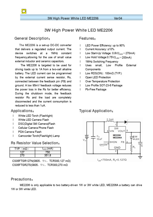
3W High Power White LED ME2206General Description : Features :Applications :Typical Application :Rs Resistor Value Selection :CS05FTGR127N(0805,1%,TCR300,127 m Ω) CS05FTGR270(0805,1%,TCR300,270 mΩPrecautions :ME2206 is only applicable to two battery-driven 1W or 3W white LED, ME2206A a battery can drive1W or 3W white LED.TYP .(mΩ)I LED (mA) 127 750 270351.8The ME2206 is a set-up DC-DC converter that delivers a regulated output current. The device switches at a 1MHz constantfrequency,allowing for the use of small value external inductor and ceramic capacitors.The ME2206 is targeted to be used fordriving loads up to 1A from a two-cell alkalinebattery. The LED current can be programmed by the external current sense resistor, Rs,connected between the feedback pin (FB) and ground. A low 95mV feedback voltage reducesthe power loss in the Rs for better efficiency. During the shutdown mode, the feedbackresistor Rs and the load are completelydisconnected and the current consumption is reduced to less than 1uA.l LED Power Efficiency: up to 90% l Current Accuracy: ±10%l Low Start-Up Voltage: 0.9V(I LED =270mA) l Low Hold Voltage:0.75V(I LED =200mA) l 1MHz Switching Frequencyl Uses small, Low Profile External Componentsl Low RDS(ON) : 100mΩ (TYP .) l Open LED Protectionl Over T emperature Protection l Low Profile SOT-23-6 Package l Pb-Free Packagel White LED Torch (Flashlight) l White LED Camera Flashl DSC(Digital Still Camera)Flash l Cellular Camera Phone Flash l PDA Camera FlashlCamcorder T orch(Flashlight) LampPin Configuration& Marking Information:SOT23-6Pin information:Pin Number Name Function1 SW Switch2 GND Ground3 FB Feedback4 SHDN Shut Down5 V OUT Output6 V IN InputAbsolute Maximum Ratings:Parameter Symbol Ratings UnitsInput Voltage V IN-0.3V~6V VSW Pin Voltage SW -0.3V~6V V SHDN, FB Pin Voltage SHDN/FB -0.3V~6V V Operating Temperature Range T OPR -40℃~85℃℃Storage Temperature Range T STG -65℃~125℃℃Lead Temperature (Soldering, 10 sec)T L 260℃℃Internal Power Dissipatio(SOT23-6)P D 400 mWElectrical CharacteristicT=25℃,Vin=2.4V,I LED =750mA,V SHDN =Vin,L=2.2uH,Cin=Cout=10uF,unless otherwise noted. Parameter Symbol Condition Min Typ Max Unit Input VoltageRangeVin 0.9 V F-0.2 V FeedbackVoltageV FB 85 95 105 mVStart-up Voltage V START Vin:0V~3VI LED =270mA0.9 VHold Voltage V HOLD Vin:3V~0VI LED =750mA~200mA0.75 VOscillatorFrequencyF OSC 1 MHz SHDN InputHighV SH Vin=1.8V 1.0 V SHDN InputLowV SL Vin=1.8V 0.4 V OverT emperature Shutdown OTS 150℃OverT emperature Hysteresis OTH 15℃MaximumOutput CurrentRangeI MAX 750 mAQuiescent Current I QI LED =0mA,Vout=3.4V,Device Switch at 1MHz 1 3mAShutdownCurrentI SD Shutdown mode 1 uASwitch onResistanceR DSON Vout=3.4V0.1 Ω Current Limit I LIM Vout=3.4V 2 A Efficiency η I LED =750mA90 % Note1:V F---LED Forward VoltageTypical Performance CharacteristicsT=25℃,L=2.2uH,Cin=Cout=10uF,unless otherwise noted.Outline Dimension。

Description:Bussmann™ series E-Rated, current-limiting, medium voltage fuses for feeder circuit, switchgear and transformer protection.Features and benefits• Current-limiting E-Rated medium voltagefuses are defined by their melting time-current characteristic that permit their electrical interchangeability with other fuses of the same E Rating.• E-Rated fuses must have a defined current response time specified by ANSI C37.46.E-Rated fuse of 100 amps and below must melt in 300 seconds at an RMS current within the range of 200% to 240% of the fuse’s nameplate current rating. E-Rated fuses greater than 100 amps must melt in 600 seconds at an RMS current within the range of 220% to 264% of the fuse’s nameplate current rating.• E-Rated fuses are physically dimensioned for easy installation in existing hardware.• Current-limiting fuses provide positive interruption even on low fault currents. The fuse limits the magnitude of electromechanical stresses in the protected apparatus.• Constructions available in ferrule, bolt-onand clip-lock, and specialty mount fuses for AMPGARD motor starters.• Outdoor rating available on select catalog numbers (requires installation in a suitable enclosure).• Open fuse indicator easily integratesinto automation schemes and speeds troubleshooting by providing a positive visual indication of fuse operation.• Optional remote contact signaling microswitch available.• 50/60Hz operating frequency for worldwide application.• Mountings are available in disconnect and non-disconnect versions with porcelain or glass poly-ester insulators.• Live parts and end fittings available.T ypical applications:• Medium voltage transformer primaryprotection• Medium voltage feeder circuit protection • Medium voltage switches• Medium voltage metal-enclosed switchgear5.5kV E-Rated medium voltage fuses for feedercircuit, switchgear and transformer protection2Technical Data 10351Effective September 2018 5.5kV E-Rated medium voltage fuses forfeeder circuit, switchgear and transformer protectionE-Rated medium voltage ferrule fusesCatalog symbols:•General purpose:• 5CLE-_E-D (10-25A)• 5CLE-_E (10-1350A)• 5HLE-_E (10-450A)•JCY-_E (1-25A)•Full range (per ANSI C37.40)•MV055F_ (10-450A)Ratings*:• Volts — 5.5kV • Amps — 1 to 1350A•Interrupting ratings — 40 to 65 kA RMS Sym* See catalog number tables for voltages, ampacities and interrupting ratings by catalog number.Agency information:•E-Rated fuses meet the performance characteristics of ANSI C37.46•UL Listed, Guide JEEG, File E240398. See catalog numbers.Dimensions (see catalog number tables for values)Recommended CLE and HLE holders:10E-D–250E Single barrel 3.0 (76.2)12.0 (304.8)15.9 (403.9)Disconnect 605HLE-PDM-D 5HLE-GDM-D CLE-DL-D CLE-DF-D300E–450E Double barrelNon-disconnect 60 3.0 (76.2)12.0 (304.8)15.9 (403.9)5HLE-PNM-E 5HLE-GNM-E CLE-NL-E —Disconnect605HLE-PDM-E5HLE-GDM-ECLE-DL-ECLE-DF-E* See page 12 for illustrations and dimensions** End fittings supplied only when required.† Disconnect mountings provide a means for fuse extraction only. Do not use a disconnect mounting for load switching or fuse removal while energized.3Technical Data 10351Effective September 20185.5kV E-Rated medium voltage fuses forfeeder circuit, switchgear and transformer protectionCLE, HLE and JCY general purpose11.2 (284) 2 (51)9 (229)401Indoor/outdoor2JCY-2E 3JCY-3E 5JCY-5E 7JCY-7E 10JCY-10E 1017.9 (455) 3 (76)14 (356)635CLE-10E-D 1015.9 (404)12 (305)5HLE-10E 1511.2 (284) 2 (51)9 (229)40JCY-15E 1512.9 (328)11.5 (292)50Indoor 5CLE-15E*1517.9 (455) 3 (76)14 (356)63Indoor/outdoor5CLE-15E-D 1515.9 (404)12 (305)5HLE-15E 2011.2 (284) 2 (51)9 (229)40JCY-20E 2012.9 (328)11.5 (292)50Indoor 5CLE-20E*2017.9 (455) 3 (76)14 (356)63Indoor/outdoor5CLE-20E-D 2015.9 (404)12 (305)5HLE-20E 2511.2 (284) 2 (51)2 (51)9 (229)40JCY-25E 2512.9 (328)11.5 (292)50Indoor5CLE-25E*2517.9 (455) 3 (76)14 (356)63Indoor/outdoor5CLE-25E-D 2515.9 (404)12 (305)5HLE-25E 3017.9 (455)14 (356)5CLE-30E 3015.9 (404)12 (305)5HLE-30E 4017.9 (455)14 (356)655CLE-40E †4015.9 (404)12 (305)5HLE-40E †5017.9 (455)14 (356)5CLE-50E †5015.9 (404)12 (305)5HLE-50E †6517.9 (455)14 (356)5CLE-65E †6515.9 (404)12 (305)5HLE-65E †8017.9 (455)14 (356)5CLE-80E †8015.9 (404)12 (305)5HLE-80E †10017.9 (455)14 (356)5CLE-100E †10015.9 (404)12 (305)5HLE-100E †12517.9 (455)14 (356)5CLE-125E †12515.9 (404)12 (305)5HLE-125E †15017.9 (455)14 (356)5CLE-150E †15015.9 (404)12 (305)5HLE-150E †17517.9 (455)14 (356)5CLE-175E †17515.9 (404)12 (305)5HLE-175E †20017.9 (455)14 (356)5CLE-200E †20015.9 (404)12 (305)5HLE-200E †25017.9 (455)14 (356)5CLE-250E †25015.9 (404)12 (305)5HLE-250E †30017.9 (455)14 (356)25CLE-300E †30015.9 (404)12 (305)5HLE-300E †35017.9 (455)14 (356)5CLE-350E †35015.9 (404)12 (305)5HLE-350E †40017.9 (455)14 (356)5CLE-400E †40015.9 (404)12 (305)5HLE-400E †45017.9 (455)14 (356)5CLE-450E †45015.9 (404)12 (305)5HLE-450E †* Fuses conform to dimensional standards established by Westinghouse.† UL Listed, Guide JEEG, File E240398.4Technical Data 10351Effective September 2018 5.5kV E-Rated medium voltage fuses forfeeder circuit, switchgear and transformer protection5.5kV Time-current curves — minimum melt for JCY-_E fuses5Technical Data 10351Effective September 20185.5kV E-Rated medium voltage fuses forfeeder circuit, switchgear and transformer protection 5.5kV Time-current curves — total clear for JCY-_E fuses6Technical Data 10351Effective September 2018 5.5kV E-Rated medium voltage fuses forfeeder circuit, switchgear and transformer protectionFigure 2Figure 3Figure 1MV055 full range15.7 (399)2 (51)12 (305)501Indoor7MV055F1CAX7E 10MV055F1CAX10E 10 3 (76)MV055F1DAX10E 15 2 (51)MV055F1CAX15E 15 3 (76)MV055F1DAX15E 20 2 (51)MV055F1CAX20E 20 3 (76)MV055F1DAX20E 25 2 (51)MV055F1CAX25E 25 3 (76)MV055F1DAX25E 30 2 (51)MV055F1CAX30E 30 3 (76)MV055F1DAX30E 40 2 (51)MV055F1CAX40E 40 3 (76)MV055F1DAX40E 50 2 (51)MV055F1CAX50E 50 3 (76)MV055F1DAX50E 65 2 (51)MV055F1CAX65E 65 3 (76)MV055F1DAX65E 80MV055F1DAX80E 100MV055F1DAX100E 125MV055F1DAX125E 150MV055F1DAX150E 175MV055F1DAX175E 200MV055F1DAX200E 2502MV055F2DAX250E 300MV055F2DAX300E 350MV055F2DAX350E 400MV055F2DAX400E 450MV055F2DAX450ERecommended CLE, HLE and MV055 fuseclips1Enclosed fuseclip 3 (76)4.14 (105)2.45 (62)3.01 (76)1.19 (30)5.64 (143)1.51 (38)0.4 (10)A3354730*Open fuseclip2See dimensions drawing1A0065Spring loaded open fuseclip39078A67G04*For single barrel applications only. Not sold in pairs.7Technical Data 10351Effective September 20185.5kV E-Rated medium voltage fuses forfeeder circuit, switchgear and transformer protection 5.5kV Time-current curves — minimum melt for MV055_ 2 inch diameter fuses.1101001000100010100.0111000005A 07A65A50A40A 30A 25A 20A 15A10AT I M E I N S E C O N D SCURRENT IN AMPERESMV055_ (2 inch diameter)8Technical Data 10351Effective September 2018 5.5kV E-Rated medium voltage fuses forfeeder circuit, switchgear and transformer protection5.5kV Time-current curves — total clear for MV055_ 2 inch diameter fuses1.01100101000100010010.110000CURRENT IN AMPEREST I M E I N S E C O N D S07A 05A65A50A40A 30A25A 20A 15A 10A MV055_ (2 inch diameter)9Technical Data 10351Effective September 20185.5kV E-Rated medium voltage fuses forfeeder circuit, switchgear and transformer protection 5.5kV Time-current curves — minimum melt for MV055_ 3 inch diameter fusesT I M E I N S E C O N D SCURRENT IN AMPERES.1101001000.0111000001000010001010010A15A20A 25A 30A40A 50A65A 80A 100A125A 150A 175A 200A 250A 300A 350A 400A 450AMV055_ (3 inch diameter)10Technical Data 10351Effective September 2018 5.5kV E-Rated medium voltage fuses forfeeder circuit, switchgear and transformer protection5.5kV Time-current curves — total clear for MV055_ 3 inch diameter fusesT I M E I N S E C O N D SCURRENT IN AMPERES.1101001000.0111000001000010001001010A15A20A25A 30A40A50A65A80A100A125A 150A 175A 200A 250A 300A 350A 400A 450AMV055_ (3 inch diameter)11Technical Data 10351Effective September 20185.5kV E-Rated medium voltage fuses forfeeder circuit, switchgear and transformer protection 5.5kV Peak let-through for MV055_ 2 and 3 inch diameter fuses1AVAILABLE CURRENT IN KILOAMPERES (RMS Symmetrical)M A X I M U M L E T -T H R U (P e a k K i l o a m p e r e s )10010.1.1110015A 20A 25A 40A 50A 65A 80A 100A 07&10A 05A125A 175A 450A 400A 300A 150A350A30A 200A 250A ABMV055_ (2 and 3 inch diameter)12Technical Data 10351Effective September 2018 5.5kV E-Rated medium voltage fuses forfeeder circuit, switchgear and transformer protectionCLE and HLE Type mountings - in (mm)5CLE-PDM-C 12.74 (323.6) 6 (152.4)25.5 (647.7)0.75 (19)1.75 (44.4) 4.5 (114.3)9.75 (247.6)605CLE-GDM-D 15.24 (387.1) 6 (152.4)25 (635)0.62 (15.7)1.75 (44.4) 4.5 (114.3)11.72 (297.7)605CLE-PDM-D 15.24 (387.1) 6 (152.4)25 (635)0.62 (15.7)1.75 (44.4) 4.5 (114.3)11.72 (297.7)605HLE-GDM-D 16.25 (412.8) 6 (152.4)23 (584.2)0.62 (15.7)1.75 (44.4) 4.5 (114.3)11.72 (297.7)605CLE-PNM-E 15.24 (387.1) 6 (152.4)25 (635)0.62 (15.7)1.42 (36.1) 4.5 (114.3)12.48 (317)605HLE-GNM-E 16.25 (412.7) 6 (152.4)23 (584.2)0.62 (15.7)1.75 (44.4) 4.5 (114.3)12.48 (317)605HLE-PNM-E16.25 (412.7)6 (152.4)23 (584.2)0.62 (15.7)1.75 (44.4)4.5 (114.3)12.48 (317)60CLE and HLE T ype disconnect mounting †CLE and HLE Type non-disconnect mounting† Disconnect mountings provide a means for fuse extraction only. Do not use a disconnect mounting for load switching or fuse removal while energized.13Technical Data 10351Effective September 20185.5kV E-Rated medium voltage fuses forfeeder circuit, switchgear and transformer protection• • •• • Amps — 10 to 900A•Interrupting ratings — 31 to 65 kA RMS Sym•0.250.38X.XX (XX.X)HCL clip-lockIndicator to be (53.8)Indicator to be (53.8)CLE four barrel bolt-onNote: 1100E and 1350E fuses require two double barrel fuses (4 total barrels) customer to parallel.14Technical Data 10351Effective September 2018 5.5kV E-Rated medium voltage fuses forfeeder circuit, switchgear and transformer protectionAHLE for Eaton AMPGARD motor starting assemblies651155AHLE-15E 205AHLE-20E 255AHLE-25E 305AHLE-30E 405AHLE-40E †505AHLE-50E †655AHLE-65E †805AHLE-80E †1005AHLE-100E †1255AHLE-125E †1505AHLE-150E †1755AHLE-175E †2005AHLE-200E †2505AHLE-250E †30025AHLE-300E †3505AHLE-350E †4005AHLE-400E †4505AHLE-450E †† UL Listed, Guide JEEG, File E240398.HCL clip-lock versions16.8 (427)3 (76)N/A651Indoor155HCL-15E 205HCL-20E 255HCL-25E 305HCL-30E 405HCL-40E †505HCL-50E †655HCL-65E †805HCL-80E †1005HCL-100E †1255HCL-125E †1505HCL-150E †20022.8 (579)5HCL-200E †2505HCL-250E †30025HCL-300E †4005HCL-400E †4505HCL-450E †5005HCL-500E 6005HCL-600E† UL Listed, Guide JEEG, File E240398.15Technical Data 10351Effective September 20185.5kV E-Rated medium voltage fuses forfeeder circuit, switchgear and transformer protectionCLE, BHLE and BHCL bolt-on versions19.2 (488) 3 (76)17.9 (455)651Indoor155BHLE-15E 205BHLE-20E 255BHLE-25E 305BHLE-30E 405BHLE-40E †505BHLE-50E †655BHLE-65E †805BHLE-80E †1005BHLE-100E †1255BHLE-125E †1505BHLE-150E †1755BHLE-175E †2005BHLE-200E †20025.1 (637)23.7 (602)5BHCL-200E 25019.2 (488)17.9 (455)5BHLE-250E †25025.1 (637)23.7 (602)5BHCL-250E 30019.2 (488)17.9 (455)25BHLE-300E †30025.1 (637)23.7 (602)5BHCL-300E 35019.2 (488)17.9 (455)5BHLE-350E †4005BHLE-400E †40025.1 (637)23.7 (602)5BHCL-400E 45019.2 (488)17.9 (455)5BHLE-450E †45025.1 (637)23.7 (602)5BHCL-450E 5005BHCL-500E 6005BHCL-600E 60028.9 (734) 4 (102)18.4 (467)405CLE-600E 75025.1 (637) 3 (76)23.7 (602)6335BHCL-750E 75028.9 (734) 4 (102)18.4 (467)4025CLE-750E 90025.1 (637) 3 (76)23.7 (602)6335BHCL-900E 110019.8 (503)4 (102)18.4 (467)3145CLE-1100E 13505CLE-1350E† UL Listed, Guide JEEG, File E240398.16Technical Data 10351Effective September 2018 5.5kV E-Rated medium voltage fuses forfeeder circuit, switchgear and transformer protection5.5kV Time-current curves — minimum melt for 5CLE-_E and 5CLE-_-D5CLE-_Curve 70548501April 16, 1999Reference # 563532Curve 70545801April 16, 1999Reference # 705458Curve 70546001April 20, 1999Reference # 705460Curve 62908902April 1999Reference # 62908917Technical Data 10351Effective September 20185.5kV E-Rated medium voltage fuses forfeeder circuit, switchgear and transformer protection5.5kV Time-current curves — total clear for 5CLE-_E and 5CLE-_-D5CLE-_Curve 70548702April 16, 1999Reference # 563533Curve 70545901April 20, 1999Reference # 705459Curve 70546101April 20, 1999Reference # 705461Curve 62908903April 1999Reference # 62908918Technical Data 10351Effective September 2018 5.5kV E-Rated medium voltage fuses forfeeder circuit, switchgear and transformer protection5.5kV Peak let-through for 5CLE-_E and 5CLE-_-D5CLE-_Curve 70548701April 1999Reference # 705487Curve 70547601April 1999Reference # 705476Curve 62908904April 1999Reference # 62908919Technical Data 10351Effective September 20185.5kV E-Rated medium voltage fuses forfeeder circuit, switchgear and transformer protection5.5kV Time-current curves — minimum melt for 5HLE-_E, 5AHLE-_E and 5BHLE-_E5HLE-_, 5BHLE-_, 5AHLE-_Curve 70548507April 16, 1999Reference # 563532Curve 70545805April 16, 1999Reference # 705458Curve 70546005April 20, 1999Reference # 70546020Technical Data 10351Effective September 2018 5.5kV E-Rated medium voltage fuses forfeeder circuit, switchgear and transformer protection5.5kV Time-current curves — total clear for 5HLE-_E, 5AHLE-_E and 5BHLE-_E5HLE-_, 5BHLE-_, 5AHLE-_Curve 70548607April 16, 1999Reference # 563533Curve 70545905April 20, 1999Reference # 705459Curve 70546105April 20, 1999Reference # 7054615.5kV Peak let-through for 5HLE-_E, 5AHLE-_E and 5BHLE-_E5HLE-_, 5BHLE-_, 5AHLE-_Curve 70548703 April 1999Reference # 705487Curve 70547603April 1999Reference # 70547621 5.5kV Time-current curves — minimum melt for 5HCL-_E5HCL-_Curve 70548505Janaury 2001Curve 70545803January 2001Curve 70546003April 2001Curve 66703401 Janaury 20015.5kV Time-current curves — total clear for 5HCL-_E5HCL-_Curve 70548605Janaury 2001Curve 70545903Janaury 2001Curve 70516103Janaury 2001Curve 66703501Janaury 200123 Effective September 201824The only controlled copy of this Data Sheet is the electronic read-only version located on the Bussmann Network Drive. All other copies of this document are by definition uncontrolled. This bulletin is intended to clearly present comprehensive product data and provide technical information that will help the end user with design applications. Bussmann reserves the right, without notice, to change design or construction of any products and to discontinue or limit distribution of any products. Bussmann also reserves the right to change or update, without notice, any technical information contained in this bulletin. Once a product has been selected, it should be tested by the user in all possible applications.Eaton and Bussmann are valuable trademarks of Eaton in the U.S. and other countries. Y ou are not permitted to use the Eaton trademarks without prior written consent of Eaton.ANSI is a registered trademark of the American National Standards AssociationIEEE is a registered trademark of the Institute of Electrical and Electronics Engineers NEMA is a registered trademark of the National Electrical Mfgrs. AssociationNFPA is a registered trademark of the National Fire Protection AssociationUL is a registered trademark of the Underwriters Laboratories, Inc.Eaton1000 Eaton Boulevard Cleveland, OH Bussmann Division 114 Old State Road Ellisville, MO 63021United States/bussmannseries © 2018 EatonAll Rights Reserved Printed in USAPublication No. 10351 - BU-SB15151September 20185.5kV Peak let-through for 5HCL -_E5HCL-_Curve 70548702January 2001Curve 70547602January 2001Curve 66703701January 2001。

T h e i n f o r m a t i o n p r o v i d e d i n t h i s d o c u m e n t a t i o n c o n t a i n s g e n e r a l d e s c r i p t i o n s a n d /o r t e c h n i c a l c h a r a c t e r i s t i c s o f t h e p e r f o r m a n c e o f t h e p r o d u c t s c o n t a i n e d h e r e i n .T h i s d o c u m e n t a t i o n i s n o t i n t e n d e d a s a s u b s t i t u t e f o r a n d i s n o t t o b e u s e d f o r d e t e r m i n i n g s u i t a b i l i t y o r r e l i a b i l i t y o f t h e s e p r o d u c t s f o r s p e c i f i c u s e r a p p l i c a t i o n s .I t i s t h e d u t y o f a n y s u c h u s e r o r i n t e g r a t o r t o p e r f o r m t h e a p p r o p r i a t e a n d c o m p l e t e r i s k a n a l y s i s , e v a l u a t i o n a n d t e s t i n g o f t h e p r o d u c t s w i t h r e s p e c t t o t h e r e l e v a n t s p e c i f i c a p p l i c a t i o n o r u s e t h e r e o f .N e i t h e r S c h n e i d e r E l e c t r i c I n d u s t r i e s S A S n o r a n y o f i t s a f f i l i a t e s o r s u b s i d i a r i e s s h a l l b e r e s p o n s i b l e o r l i a b l e f o r m i s u s e o f t h e i n f o r m a t i o n c o n t a i n e d h e r e i n .Product data sheetCharacteristicsABLM1A12021Regulated Power Supply, 100-240 V AC, 12 V2.1 A, single phase, ModularMainRange of product Modicon Power Supply Product or component typePower supplyPower supply type Regulated switch mode Variant option ModularNominal input voltage 100...240 V AC single phase 100...240 V AC 2 phases Input voltage limits 90...264 V AC Kw Rating 25 W Output voltage 12 V DC Power supply output current2.1 AComplementaryNominal network frequency 50…60 Hz Network system compatibilityTN TT ITMaximum leakage current 0.25 mA 240 V ACInput protection typeIntegrated fuse (not interchangeable) 3.15 A External protection (recommended) 20 A B External protection (recommended) 20 A C External protection (recommended) 4 A B External protection (recommended) 4 A C Inrush current25 A 115 V 50 A 230 V [Ue] rated operational voltage 115 V AC 0.48230 V AC 0.38Efficiency85 % 115 V AC 85 % 230 V AC Output voltage adjustment 12...15 V Power dissipation in W 4.6 WCurrent consumption < 0.8 A 115 V AC < 0.6 A 230 V AC Turn-on time < 2 sHolding time> 20 ms 115 V AC > 60 ms 230 V AC Startup with capacitive loads 3000 µF Residual ripple< 100 mV Expected capacitor life time 10 year(s)Meantime between failure [MTBF]5000000 H at 77 °F (25 °C), full load 1000000 h at 131 °F (55 °C), 80 % loadOutput protection typeAgainst overload and short-circuits automatic reset Against over temperature manual reset Against overvoltage manual resetConnections - terminals Screw connection 0.5...1.5 mm², AWG 20...AWG 16) without wire end ferrule Screw connection 0.5...1 mm², AWG 20...AWG 18) with wire end ferrule Line and load regulation < 0.5 %line < 1 %loadStatus LED Output voltage 1 LED Green)Depth2.19 in (55.6 mm)Maximum Height3.58 in (91 mm)Width1.42 in (36 mm)Net weight0.37 lb(US) (0.170 kg)Output coupling SerialMounting support Top hat type TH35-15 rail IEC 60715Top hat type TH35-7.5 rail IEC 60715Double-profile DIN railPanel mountingEnvironmentStandards EN 62368-1EN/IEC 61010-1EN 61010-2-201EN/IEC 61204-3EN 61000-6-1EN 61000-6-2EN 61000-6-3EN 61000-6-4EN 61000-3-2EN 61000-3-3EN 61000-4-3UL 1310UL 62368-1UL 61010-2-201UL 61010-1-201CSA C22.2 No 62368-1CSA C22.2 No 61010-2-201CSA C22.2 No 61010-1-201Product certifications CECUL ListedCUL RecognizedRCMCB SchemeOperating altitude< 6561.68 ft (2000 m) overvoltage category III2000 m...5000 m overvoltage category IIShock resistance100 m/s² 11 msIP degree of protection IP20Ambient air temperature for operation-13…131 °F (-25…55 °C) without current derating)131…158 °F (55…70 °C) with current derating of 2.67 % per °C)Ambient air temperature for storage-40…185 °F (-40…85 °C)Relative humidity0…95 % without condensationElectrical shock protection class Class II without PE connectionPollution degree2Vibration resistance 3 mm 2…9 Hz)IEC 60721-3-310 m/s² 9…200 Hz)IEC 60721-3-3Electromagnetic immunity Immunity to electrostatic discharge 6 kV contact discharge) EN/IEC 61000-4-2Immunity to electrostatic discharge 9 kV air discharge) EN/IEC 61000-4-2Electromagnetic field immunity test 10 V/m 80 MHz...2 GHz) EN/IEC 61000-4-3Electromagnetic field immunity test 5 V/m 2...2.7 GHz) EN/IEC 61000-4-3Electromagnetic field immunity test 3 V/m 2.7...6 GHz) EN/IEC 61000-4-3Immunity to fast transients 4 kV on input-output) EN/IEC 61000-4-4Surge immunity test 3 kV between power supply and earth) EN/IEC 61000-4-5Surge immunity test 1.5 kV between phases) EN/IEC 61000-4-5Immunity to conducted disturbances 10 Vrms 0.15...80 MHz) EN/IEC 61000-4-6Immunity to magnetic fields 30 A/m 50...60 Hz) EN/IEC 61000-4-8Immunity to voltage dips 100 % 1 cycle) EN/IEC 61000-4-11Immunity to voltage dips 60 % 10 cycles) EN/IEC 61000-4-11Immunity to voltage dips 30 % 25 cycles) EN/IEC 61000-4-11Disturbing field emission IEC 55016-2-3Limits for harmonic current emissions IEC 61000-3-3Micro-cuts and voltage fluctuation IEC 55016-1-2Micro-cuts and voltage fluctuation IEC 55016-2-1Electromagnetic emission Conducted emissions EN 61000-6-3Radiated emissions EN 61000-6-4Dielectric strength3000 V AC input/outputOffer SustainabilityREACh free of SVHC YesEU RoHS Directive Pro-active compliance (Product out of EU RoHS legal scope)EU RoHSDeclarationMercury free YesRoHS exemption information YesChina RoHS Regulation China RoHS DeclarationWEEE The product must be disposed on European Union markets following specificwaste collection and never end up in rubbish bins.Dimensions DrawingsElectrical Safety●If the unit is use in a manner not specified by the manufacturer, the protection provided by the equipment may be impaired.●For means of disconnection a switch or circuit breaker, located near the product, must be included in the installation. A marking asdisconnecting device for the product is required.●The device has an internal fuse. The unit is tested and approved with branch circuit protective device up to 20A. This circuit breaker canbe used as disconnecting device.DimensionsSide and Rear ViewConnections and SchemaRegulated Switch Mode Power Supplies Correct Parallel Connection(1) :LoadIncorrect Parallel Connection(1) :LoadABLx1Axxxxx-1 = ABLx1Axxxxx-2max 2 x ABLx1AxxxxxL1 = L2∆V max 25 mVL Load < 90% 2 x L nomSeries Connection(1) :V out1(2) :V out2(3) : 2 x Diode, V RPM> 2 x V out1/2, L F > 2 x L nom1/2(4) :V Load = 2 x V out(5) :LoadOutput Voltage Balancing(1) :R Load1(2) :R Load2R Load1= R Load2L1= L 2= ~ L nomPerformance Curves Performance CurveX :Ambient Temperature (ºC) Y :Percentage of Max Load (%)1 :Mounting A2 :Mounting BMounting and Clearance Mounting(1) :Mounting A(2) :Mounting BIncorrect Mounting。
主流显示器的工程模式选购LCD时,你是否想了解它们采用的是什么面板;交易二手LCD成交前,你是不是应该查看一下机器的出厂日期和使用时间;你是否还想更深入地调节LCD,以便达到满意的显示效果。
如果你不知道该怎样做,没关系,当我们破解了LCD的“摩斯密码”——工程模式之后,自然就能找到它们了。
一直以来,大家都或多或少地对显示器的工程模式抱有一颗好奇心,而随着各品牌旗下LCD系列的升级,它们在调用工程模式的方法以及工程模式所具有的功能方面都有了一些变化,所以系统地对目前主流品牌产品的工程模式进行一些介绍,就显得很有必要了。
接下来,我们就从目前主流LCD品牌中选取它们具有代表性的产品,通过分析个例的工程模式,尽可能地让读者对该品牌显示器的工程模式有更多的了解,并能应用在其它型号的显示器上,使他们能更好地利用工程模式来调节显示器或为他们的选购提供参考。
什么是LCD的工程模式LCD的工程模式,也可称为工厂模式,它是显示器厂家在设计电路时预留在LCD中的一些功能,但一般情况下这些功能并不对用户开放,用户需要通过特殊的方式才能进入工程模式。
飞利浦开门“密码”以飞利浦最新的产品220X1为例,首先关闭它的电源开关,然后同时按住“OK/MEMU”键与“AUTO”键,再按下电源开关启动显示器。
这时,220X1的工程模式就被打开了。
工程模式解析按照以上的方法开启220X1的工程模式后,要如何进入控制菜单呢?这时我们只需要按下“OK/MEMU”键,调出主菜单,在“输入”选项中,除了“VGA”和“DVI”之外,多出了“Factory”选项,这就是工程模式。
另外,我们也可通过“INP UT”键一键调出工程模式菜单。
飞利浦220X1的工程模式菜单进入工程模式菜单后,就能看到产品的出厂日期、面板型号以及序列号。
除此之外,菜单下面提供了亮度、对比度的调整。
值得一提的是,飞利浦的色温调节选项很丰富,包括了5000K、6500K、7500K 、8200K 、9300K、11500K等不同色温值下的调节项目,在各品牌中是最多的。
深圳市众显创新科技有限公司首页 产品展示 公司介绍 联系方式公司首页 > 产品展示 > LED 升压板 > ZX-L0702LED 升压板 奇美,群创,AUO ,LG 等屏用众显创新科技,专业生产LED 升压板,LED 背光驱动电源,LED 恒流板,性能稳定,价格一流,广泛应用于目前市面上常用的LED 液晶屏,奇美,群创,LG,AUO,夏普等等LED背光的液晶屏。
产品名称:LED 升压板 奇美,群创,AUO ,LG 等屏用产品型号:ZX-L0702产品品牌:众显最少订量: 5 pcs ; 13CNY (不含税)立即询价加入询价篮查看询价篮 (0个产品)发邮件向朋友推荐加入到站内收藏夹ZX-L0702 产品描述ZX-L0704输入电压:5.5-25V 输出电压:20-58V输出电流:20MA-60MA/每组 ON:5V OFF:0V 调亮电压:0-5V 尺寸:80*35mm以上电气参数根据所用屏不同而改变。
适用范围:7-25寸LED 背光液晶屏,包括群创,奇美,LG,三星,AU,夏普,,,, 可按照客户要求开发!适用屏型号群创 M230WA01-ED MT230DW01 V.2T236H1-P01-L01-VER C1 MT190AW02 MT185GW01 AT102TN03 M215HW01 MT215DWO1M236H3-L01 ver 0.0 M236H3-L05 ver 2.0 奇美M185B3-LA1M185B3-L01 VER1.0 V185B1-LE1M215H3-L01 VER2.0 M215H3-LA1M236H3-L01 VER0.0 M236H3-LA2 VER1.0 M240HW01 V6 M236ID1WF1-1M156B3-L01 VER2.1 LM215WF4 M236ID1WF1-1M156B3-LA1 2.1(LED) V236H1-LE2LGLM215WF3-SLA1 LC215EUE-TCA1LM220WE5-TLA1 .10p LP154WP3-TLA1 LP154WP3-TLA2 LM230WF3-SL-B1 LM230WF5-TLA1 AUOM185XW01_V6 M185XW01 VD M215HW01 V6 M215HW01 VB M240HW01 V6夏普LQ215M1LGN2 LQ185K1Lxxx_LED 升压板 [7] 液晶高压板 [4] LED 背光驱动板 [1] 产品展示公司信息深圳市众显创新科技有限公司[ 已验证 ]成立时间:2009-10-19 VIP 会员:第二个月您好,roger [退出]© 2011 全球液晶屏交易中心 - 屏库 版权所有三星LTM185AT04 LTM200KT07 LTM230HT05 中华CALL185WA01 CALL215FA04-KZX-L0702 产品图片图片1ZX-L0702 配屏型号 (57个)M215HW01 V6 M215HW01 V8 M215HW01 VB M215HW01 VE M215HW02 V0 M240HW01 V1 M240HW01 V6 M240HW01 VB M240HW02 V1 T240HW01 V0 T260XW06 V0 MT185GW01 V.1 MT185GW01 V.3 MT190AW02 V.3 MT190AW02 V.W MT190EN02 V.W MT215DW01 V.1 MT215DW01 V.3 MT220WW01 V.T MT230DW01 V.1 MT230DW01 V.2 M185B3-L01 M185B3-LA1 M200O3-L01 M200O3-LA1 M215H3-L01 M215H3-LA1 M220Z3-L03 M220Z3-L07 M220Z3-LA1 M236H3-L01 M236H3-L02 M236H3-LA2 V185B1-LE1 V216B1-LE1 V236H1-DE01 V260B2-LE1 CLAA215FA04 CLAA220UA01 LC215EUE-TCA1 LC216EXN-SCA1 LC260EUN-SCA1 LM200WD3-TLA1 LM215WF4-TLA1 LM215WF4-TLA4 LM220WE5-TLA1 LM230WF5-TLA1 LM240WU6-SDA1 LQ185T1LGN3 LQ190E1LX51 LQ230M1LW11 LQ231U1LW31 LQ231U1LW32 M236H3-L05 TT260GW01 V.0V236H1-LE2V215H1-LE1联系方式公司名称:深圳市众显创新科技有限公司营业地址:中国广东省深圳市布吉西环路布吉一村工业区11栋4楼联 系 人:幸卓新 先生 销售电话号码:86-755-89672134传真号码:86-755-89672132移动电话:86-134********公司网址:△ 返回本页顶部。
T h e i n f o r m a t i o n p r o v i d e d i n t h i s d o c u m e n t a t i o n c o n t a i n s g e n e r a l d e s c r i p t i o n s a n d /o r t e c h n i c a l c h a r a c t e r i s t i c s o f t h e p e r f o r m a n c e o f t h e p r o d u c t s c o n t a i n e d h e r e i n .T h i s d o c u m e n t a t i o n i s n o t i n t e n d e d a s a s u b s t i t u t e f o r a n d i s n o t t o b e u s e d f o r d e t e r m i n i n g s u i t a b i l i t y o r r e l i a b i l i t y o f t h e s e p r o d u c t s f o r s p e c i f i c u s e r a p p l i c a t i o n s .I t i s t h e d u t y o f a n y s u c h u s e r o r i n t e g r a t o r t o p e r f o r m t h e a p p r o p r i a t e a n d c o m p l e t e r i s k a n a l y s i s , e v a l u a t i o n a n d t e s t i n g o f t h e p r o d u c t s w i t h r e s p e c t t o t h e r e l e v a n t s p e c i f i c a p p l i c a t i o n o r u s e t h e r e o f .N e i t h e r S c h n e i d e r E l e c t r i c I n d u s t r i e s S A S n o r a n y o f i t s a f f i l i a t e s o r s u b s i d i a r i e s s h a l l b e r e s p o n s i b l e o r l i a b l e f o r m i s u s e o f t h e i n f o r m a t i o n c o n t a i n e d h e r e i n .Product data sheetCharacteristicsMETSEPM2220EasyLogic PM2220, Power & Energy meter,up to the 15th harmonic, LCD display, RS485,class 1MainRange EasyLogic Product name EasyLogic PM2200Device short name PM2220Product or component typePower meterComplementaryDevice application Power monitoring Sub billingPower quality analysis Total harmonic distortion Up to the 15th harmonicType of measurementApparent power min/max, totalActive and reactive power min/max, total Current min/max, avg Voltage min/max, avg Frequency min/max, avgTotal current harmonic distortion THD (I) per phase Total voltage harmonic distortion THD (U) per phase Power factor min/max, avg Apparent energy totalActive and reactive energy totalMetering typeActive, reactive, apparent energy (signed, four quadrant)Current I, I1, I2, I3Peak demand currentsPeak demand power PM, QM, SM Unbalance currentActive power P, P1, P2, P3Reactive power Q, Q1, Q2, Q3Demand power P, Q, SVoltage U, U21, U32, U13, V, V1, V2, V3Apparent power S, S1, S2, S3Calculated neutral currentAccuracy classClass 1 active energy conforming to IEC 62053-21Class 1 reactive energy conforming to IEC 62053-24Class 5 harmonic distorsion (I THD & U THD)Measurement accuracyApparent power +/- 1 %Active energy +/- 1 %Reactive energy +/- 1 %Active power +/- 1 %Voltage +/- 0.5 %Power factor +/- 0.01Current +/- 0.5 %Frequency +/- 0.05 %Measurement current 5…6000 mAMeasurement voltage35…480 V AC 50/60 Hz between phases20…277 V AC 50/60 Hz between phase and neutral 480…999000 V AC 50/60 Hz with external VT Frequency measurement range 45…65 Hz[Us] rated supply voltage44...277 V AC 45...65 Hz +/- 10 %44...277 V DC +/- 10 %Network frequency50 Hz60 HzRide-through time100 Ms 120 V AC typical400 Ms 230 V AC typical50 ms 125 V DC typicalLine Rated Current1 A5 AMaximum power consumption in VA6 VA 277 V ACMaximum power consumption in W 3.3 W (power lines (AC))2 W at 277 V (power lines (DC))Input impedance Current (impedance <= 0.3 mOhm)Voltage (impedance > 5 MOhm)Tamperproof of settings Protected by access codeDisplay type Backlit LCDDisplay colour MonochromeDisplay resolution128 x 128 pixelsDemand intervals Configurable from 1 to 60 minInformation displayed Demand current (past value)Demand current (present value)Demand power (past value)Demand power (present value)VoltageCurrentFrequencyEnergy consumptionHarmonic distortionPower factorActive powerApparent powerReactive powerUnbalanced in %Harmonic amplitudeControl type 4 x buttonLocal signalling Red LED: output signal 1...9999000 pulse/ k_h (kWh, kVAh, kVARh)Green LED: module operation and integrated communicationNumber of inputs0Number of outputs0Communication port protocol Modbus RTU 4800 bps, 9600 bps, 19200 bps, 38.4 Kbps even/odd or none - 2wires 2500 VCommunication port support Screw terminal block: RS485Data recording Time stampingMin/max for 8 parametersFunction available Real time clockSampling rate64 samples/cycleCybersecurity Enable/disable communication portsCommunication service Remote monitoringLanguage SpanishFrenchEnglishRussianPortugueseGermanChineseProduct certifications CE IEC 61010-1CULus UL 61010-1CULus conforming to CSA C22.2 No 61010-1RCMEACC-TickMounting mode Clip-onMounting position VerticalMounting support FrameworkProvided equipment 1 x Installation guideMeasurement category Category III 480 VCategory II 480…600 VElectrical insulation class Double insulationClass IIFlame retardance V-0 conforming to UL 94Connections - terminals Current transformer screw connection bottom) 6Voltage inputs screw connection top) 4Material PolycarbonateWidth 3.78 in (96 mm)Depth Total 3.00 in (76.09 mm)Embedded 2.43 in (61.64 mm)Height 3.78 in (96 mm)Net Weight10.58 oz (300 g)Compatibility code PM2220EnvironmentService life7 year(s)IP degree of protection IP54 front: conforming to IEC 60529Body IP30 IEC 60529Relative humidity5…95 % 122 °F (50 °C)Pollution degree2Ambient air temperature for operation14…140 °F (-10…60 °C)Ambient air temperature for storage-13…158 °F (-25…70 °C)Operating altitude<= 6561.68 ft (2000 m)Electromagnetic compatibility Electrostatic discharge conforming to IEC 61000-4-2Radiated radio-frequency electromagnetic field immunity test IEC 61000-4-3Electrical fast transient/burst immunity test conforming to IEC 61000-4-4Surge immunity test IEC 61000-4-5Conducted RF disturbances conforming to IEC 61000-4-6Magnetic field at power frequency conforming to IEC 61000-4-8Voltage dips and interruptions immunity test IEC 61000-4-11Emission tests conforming to FCC part 15 class AOvervoltage category IIIOrdering and shipping detailsGTIN03606480800177Nbr. of units in pkg.1Package weight(Lbs)9.52 oz (270 g)Packing UnitsUnit Type of Package 1PCEPackage 1 Height 3.78 in (9.6 cm)Package 1 width 2.65 in (6.72 cm)Package 1 Length 4.00 in (10.16 cm)Unit Type of Package 2BB1Number of Units in Package 21Package 2 Weight12.80 oz (363 g)Package 2 Height 4.53 in (11.5 cm)Package 2 width 3.43 in (8.7 cm)Package 2 Length 4.72 in (12 cm)Unit Type of Package 3S03Number of Units in Package 318Package 3 Weight15.48 lb(US) (7.02 kg)Package 3 Height11.81 in (30 cm)Package 3 width11.81 in (30 cm)Package 3 Length15.75 in (40 cm)Offer SustainabilitySustainable offer status Green Premium productREACh Regulation REACh DeclarationEU RoHS Directive Compliant EU RoHS DeclarationMercury free YesRoHS exemption information YesChina RoHS Regulation China RoHS Declaration Circularity Profile End Of Life Information。
SPECIFICATIONFOR APPROVALTitle22”WSXGA+ TFT LCDBUYER DellMODEL))((Final SpecificationPreliminary Specification APPROVED BYSIGNATUREDATE///Please return 1 copy for your confirmation withyour signature and comments.*When you obtain standard approval,please use the above model name without suffixLM220WE1*MODEL TLA1SUFFIXLG.Philips LCD Co., Ltd.SUPPLIER MNT Products Engineering Dept.LG. Philips LCD Co., LtdD.Y.Lee / EngineerPREPARED BYJohn.Kim / Manager REVIEWED BYS.G.Hong / G.ManagerSIGNATUREDATEAPPROVED BYContentsNoITEM PageCOVER 13-2INTERFACE CONNECTIONS 9159PRECAUTIONS283-5COLOR INPUT DATA REFERNECE 7-2EMC 268PACKING278-1DESIGNATION OF LOT MARK 278-2PACKING FORM 27CONTENTS2RECORD OF REVISIONS31GENERAL DESCRIPTION 42ABSOLUTE MAXIMUM RATINGS 53ELECTRICAL SPECIFICATIONS 63-1ELECTRICAL CHARACTREISTICS 63-3SIGNAL TIMING SPECIFICATIONS 133-4SIGNAL TIMING WAVEFORMS 143-6POWER SEQUENCE 164OPTICAL SFECIFICATIONS 175MECHANICAL CHARACTERISTICS 226RELIABILITY257INTERNATIONAL STANDARDS 267-1SAFETY 26RECORD OF REVISIONSRevision No Revision Date Page DESCRIPTION0.0May. 20. 2006-Preliminary Specification of LM220WE1-TLA1(Draft)0.1Jun. 19. 2006-Preliminary Specification of LM220WE1-TLA11. General DescriptionLM220WE1 is a Color Active Matrix Liquid Crystal Display with an integral Cold Cathode Fluorescent Lamp(CCFL) backlight system. The matrix employs a-Si Thin Film Transistor as the active element.It is a transmissive type display operating in the normally black mode. It has a 22 inch diagonally measured active display area with WSXGA+ resolution (1050 vertical by 1680 horizontal pixel array)Each pixel is divided into Red, Green and Blue sub-pixels or dots which are arranged in vertical stripes.Gray scale or the brightness of the sub-pixel color is determined with a 8-bit gray scale signal for each dot,thus, presenting a palette of more than 16,7M colors with A-FRC(Advanced Frame Rate Control).It has been designed to apply the 8Bit 2 port LVDS interface.I t i s in te nded to support displays where high brightness, super wide viewing angle,high color saturation, and high color are important.General FeaturesActive Screen Size 21.995 inches(558.673mm) diagonal (Aspect ratio 16:10)Outline Dimension 493.7(H) x 320.1 (V) x 16.5(D) mm (Typ.)Pixel Pitch 0.282mm x 0.282mmPixel Format 1680 horiz. By 1050 vert. Pixels RGB strip arrangement Color Depth 16,7 M colorsViewing Angle (CR>10)Viewing Angle Free ( R/L 160(Typ.), U/D 160(Typ) )Luminance, White 300 cd/m 2 (Center 1 point, Typ.)Power Consumption Total 28.755 Watt(Typ.) (3.875 Watt@V LCD , 24.88 Watt@300cd/[LAMP=7.5mA])Weight2,800 g (Typ.)Display Operating Mode Transmissive mode, Normally WhiteSurface Treatment Hard coating(3H) & Anti-glare (Haze 25%) treatment of the front polarizerTFT-LCD Panel (1680 ×1050 pixels)Source Driver CircuitTiming ControlBlockPower Circuit BlockCN1(30pin)Backlight Assembly(4 CCFL)RGB, Dclk, DE Hsync, Vsync (LVDS 2 port)V LCD (+5V)G1050G1S1680S1Gate Driver circuitCN2, 3(2PIN)CN4, 5(2PIN)V Lamp V Lamp2. Absolute Maximum RatingsThe following are maximum values which, if exceeded, may cause faulty operation or damage to the unit.Table 1. ABSOLUTE MAXIMUM RATINGSNote : 1. Temperature and relative humidity range are shown in the figure below.Wet bulb temperature should be 39 C Max, and no condensation of water.Values Parameter Min Max Units Power Input Voltage V LCD -0.3+5.5Vdc±Operating Temperature T OP 050C1Storage Temperature TST-2060 C1Operating Ambient Humidity H OP 1090%RH 1Storage HumidityH ST1090%RH1Notes Symbol3. Electrical Specifications 3-1. Electrical CharacteristicsIt requires two power inputs. One is employed to power the LCD electronics and to drive the TFT array and liquid crystal. The second input power for the CCFL, is typically generated by an inverter. The inverter is an external unit to the LCDs.Table 2_1. ELECTRICAL CHARACTERISTICSNote :1. The specified current and power consumption are under the V LCD =5.0V, 25 ±2 C,f V =60Hz condition whereas mosaic pattern(8 x 6) is displayed and f V is the frame frequency.2. The current is specified at the maximum current pattern.3. The duration of rush current is about 2ms and rising time of power Input is 500us ±20%.(min.).ValuesParameter Symbol MinTypMaxMODULE :Power Supply Input Voltage V LCD 4.5 5.0 5.5Vdc -775891mA 1Power Consumption P LCD - 3.875 4.455Watt 1Rush currentI RUSH--3A3Power Supply Input Current I LCD -9591103mA 2UnitNotesMosaic Pattern(8 x 6)White : 255Gray Black : 0GrayMaximum current patternBlack PatternTable 2_2. ELECTRICAL CHARACTERISTICSNote : The design of the inverter must have specifications for the lamp in LCD Assembly .The performance of the Lamp in LCM, for example life time or brightness, is extremely influenced by the characteristics of the DC-AC inverter. So all the parameters of an inverter should be carefully designed so as not to produce too much leakage current from high-voltage output of the inverter.When you design or order the inverter, please make sure unwanted lighting caused by the mismatch of the lamp and the inverter (no lighting, flicker, etc) never occurs. When you confirm it, the LCD–Assembly should be operated in the same condition as installed in you instrument. Do not attach a conducting tape to lamp connecting wire.If the lamp wire attach to a conducting tape, TFT-LCD Module has a low luminance and the inverter has abnormal action. Because leakage current is occurred between lamp wire and conducting tape.1. Specified values are for a single lamp.2. Operating voltage is measured at 25 ±2 C. The variance of the voltage is ±10%.3. The voltage above V S should be applied to the lamps for more than 1 second for start-up.(Inverter open voltage must be more than lamp starting voltage.)Otherwise, the lamps may not be turned on. The used lamp current is the lamp typical current.4. Lamp frequency may produce interface with horizontal synchronous frequency and as a result this may cause beat on the display. Therefore lamp frequency shall be as away possible from the horizontal synchronous frequency and from its harmonics in order to prevent interference.5. Let’s define the brightness of the lamp after being lighted for 5 minutes as 100%.T S is the time required for the brightness of the center of the lamp to be not less than 95%.6. The lamp power consumption shown above does not include loss of external inverter.The used lamp current is the lamp typical current. (P BL = V BL x I BL x N Lamp )7. The life is determined as the time at which brightness of the lamp is 50% compared to that of initial value at the typical lamp current on condition of continuous operating at 25 ±2 C.ValuesParameterSymbol Min Typ Max LAMP :Operating Voltage V BL -TBD -V RMS 1, 2Established Starting VoltageVs1, 3at 25 C at 0 CDischarge Stabilization Time Ts 3Min 1, 5Power Consumption P BL24.8827.37Watt 61,550V RMS Operating Frequency f BL 406080kHz 41,250V RMS Operating CurrentI BL 3.07.58.0mA RMS 1Life Time50,000Hrs1, 7Unit NotesI pI -p * Asymmetry rate:| Ip–I–p| / Irmsx 100% * Distortion rateIp(or I–p) / Irms8. The output of the inverter must have symmetrical(negative and positive) voltage waveform andsymmetrical current waveform (Unsymmetrical ratio is less than 10%). Please do not use the inverter which has unsymmetrical voltage and unsymmetrical current and spike wave.Requirements for a system inverter design, which is intended to have a better display performance, a better power efficiency and a more reliable lamp, are following.It shall help increase the lamp lifetime and reduce leakage current.a. The asymmetry rate of the inverter waveform should be less than 10%.b. The distortion rate of the waveform should be within 2 10%.* Inverter output waveform had better be more similar to ideal sine wave.9. The inverter which is combined with this LCM, is highly recommended to connect coupling(ballast)condenser at the high voltage output side. When you use the inverter which has not coupling(ballast) condenser, it may cause abnormal lamp lighting because of biased mercury as time goes.10.In case of edgy type back light with over 4 parallel lamps, input current and voltage wave form shouldbe synchronized3-2. Interface ConnectionsTable 3. MODULE CONNECTOR(CN1) PIN CONFIGURATION LCD Connector(CN1) : FI-XB30SRL-HF11 (Manufactured by JAE) or Equivalent Mating Connector : FI-XC30C2L (Manufactured by JAE) or Equivalent 123456789101112131415161718192021222324252627282930Pin NoFR0M FR0P FR1M FR1P FR2M FR2P GNDFCLKINM FCLKINP FR3M FR3P SR0M SR0P GND SR1M SR1P GND SR2M SR2P SCLKINM SCLKINP SR3M SR3P GND NC NCPWM_OUT V LCD V LCD V LCDMinus signal of odd channel 0 (LVDS)Plus signal of odd channel 0 (LVDS)Minus signal of odd channel 1 (LVDS)Plus signal of odd channel 1 (LVDS)Minus signal of odd channel 2 (LVDS)Plus signal of odd channel 2 (LVDS)GroundMinus signal of odd clock channel (LVDS)Plus signal of odd clock channel (LVDS)Minus signal of odd channel 3 (LVDS)Plus signal of odd channel 3 (LVDS)Minus signal of even channel 0 (LVDS)Plus signal of even channel 0 (LVDS)GroundMinus signal of even channel 1 (LVDS)Plus signal of even channel 1 (LVDS)GroundMinus signal of even channel 2 (LVDS)Plus signal of even channel 2 (LVDS)Minus signal of even clock channel (LVDS)Plus signal of even clock channel (LVDS)Minus signal of even channel 3 (LVDS)Plus signal of even channel 3 (LVDS)GroundNo Connection (I2C Serial interface for P-VCOM)No Connection (I2C Serial interface for P-VCOM)PWM_OUT signal for control burst frequency of Inverter Power Supply +5.0V Power Supply +5.0V Power Supply +5.0VSecond dataFirst dataNote: 1. NC: No Connection.2. All GND(ground) pins should be connected together and to Vss which should also be connected to the LCD’s metal frame.3. All V LCD (power input) pins should be connected together.4. Input Level of LVDS signal is based on the IEA 664 Standard.5. RWM_OUT signal is synchronized with vertical frequency.It’s frequency is 3 times of vertical frequency, and it’s duty ratio is 50%.If you don’t use this pin, it is no connection.User Connector Diagram120#30#1FI-XB30SRL-HF11 (JAE)Rear view of LCM#1#30Input connectorComponentsPCBBack LightTable 4. REQUIRED SIGNAL ASSIGNMENT FOR Flat Link (TI:SN75LVDS83) Transmitter Notes : Refer to LVDS Transmitter Data Sheet for detail descriptions.Pin #Require SignalPin NamePin #Require SignalPin Name1Power Supply for TTL Input V CC 29Ground pin for TTL GND 2TTL Input (R7)D530TTL Input (DE)D263TTL Input (R5)D631TTL Level clock Input T X CLKIN 4TTL Input (G0)D732Power Down Input PWR DWN 5Ground pin for TTL GND 33Ground pin for PLL PLL GND 6TTL Input (G1)D834Power Supply for PLL PLL V CC 7TTL Input (G2)D935Ground pin for PLL PLL GND 8TTL Input (G6)D1036Ground pin for LVDSLVDS GND 9Power Supply for TTL Input V CC 37Positive LVDS differential data output 3TxOUT3 10TTL Input (G7)D1138Negative LVDS differential data output 3TxOUT3 11TTL Input (G3)D1239Positive LVDS differential clock output T X CLKOUT 12TTL Input (G4)D1340Negative LVDS differential clock output T X CLKOUT 13Ground pin for TTL GND 41Positive LVDS differential data output 2T X OUT2 14TTL Input (G5)D1442Negative LVDS differential data output 2T X OUT2 15TTL Input (B0)D1543Ground pin for LVDS LVDS GND 16TTL Input (B6)D1644Power Supply for LVDSLVDS V CC 17Power Supply for TTL Input V CC 45Positive LVDS differential data output 1T X OUT1 46Negative LVDS differential data output 1T X OUT1 18TTL Input (B7)D1747Positive LVDS differential data output 0T X OUT0 48Negative LVDS differential data output 0T X OUT0 19TTL Input (B1)D1820TTL Input (B2)D1949Ground pin for LVDS LVDS GND21Ground pin for TTL Input GND 22TTL Input (B3)D2023TTL Input (B4)D2150TTL Input (R6)D2751TTL Input (R0)D024TTL Input (B5)D2225TTL Input (RSVD)D2352TTL Input (R1)D153Ground pin for TTL GND 26Power Supply for TTL Input V CC 54TTL Input (R2)D255TTL Input (R3)D327TTL Input (HSYNC)D2456TTL Input (R4)D428TTL Input (VSYNC)D25Table 5. BACKLIGHT CONNECTOR PIN CONFIGURATION(CN2,CN3,CN4,CN5)<BACKLIGHT CONNECTOR DIAGRAM>The backlight interface connector is a model BHSR-02VS-2(or 1674817-1:manufactured by AMP)(CN2/CN3/CN4/CN5) manufactured by JST. The mating connector part number are SM02B-BHSS-1-TB(2pin) or equivalent. The pin configuration for the connector is shown in the table below.Up SideDown SideCN2CN3CN4CN5Lamp1Lamp2Lamp3Lamp4Pin Symbol Description NOTES High Voltage for Lamp 12Low Voltage for LampHV LV12Notes: Hsync period and Hsync width-active should be even number times of t CLK . If the value is odd numbertimes of t CLK , display control signal can be asynchronous.In order to operate this LCM a Hsync, Vsyn, and DE(data enable) signals should be used.1. The performance of the electro-optical characteristics may be influenced by variance of the verticalrefresh rates.2. Vsync and Hsync should be keep the above specification.3. Hsync Period, Hsync Width, and Horizontal Back Porch should be any times of of characternumber(8).4. The polarity of Hsync, Vsync is not restricted.3-3. Signal Timing SpecificationsTable 6. Timing TableThis is the signal timing required at the input of the User connector. All of the interface signal timing should be satisfied with the following specifications for it’s proper operation.ITEMSymbolMinTypMaxUnitNotePeriodt CLK13.316.821.1nsFrequency -47.37559.575MHz Periodt HP 8809201200t CLKFrequency f H 51.49564.67481.522KHzWidth t WH 81616t CLK t HPFrequency f V 486077Hz Horizontal Back Porch t HBP 1640200Horizontal Blank -4080360Vertical Blank-1030250t CLKVertical Back Porch t VBP52139t HPHorizontal Front Porcht HFP164096Vertical Valid t VV 105010501050Vertical Front Porch t VFP 236Widtht WV 36205HsyncPeriodt VP 106010801300t HP VsyncHorizontal Valid t HV 840840840DE (Data Enable)2pixel/clkDCLK3-4. Signal Timing Waveforms0.7V CC0.3V CCt CLKInvalid dataValid dataInvalid dataInvalid dataInvalid dataPixel 0,0Pixel 2,0Pixel 1,0Pixel 3,0DE(Data Enable)Valid data0.5 V CCt HPt HBPt HVt HFPt VPt WVt VBPt VVt VFPHSyncVSyncDE(Data Enable)DE(Data Enable)DCLKFirst dataSecond dataHsync, Vsync, DE, Datat WH3-5. Color Data ReferenceThe Brightness of each primary color(red,green,blue) is based on the 8-bit gray scale data input for the color;the higher the binary input, the brighter the color. The table below provides a reference for color versus data input.Table 7. COLOR DATA REFERENCEInput Color DataRED MSB LSB GREEN MSB LSB BLUEMSB LSBBlack 0 0 0 0 0 0 0 00 0 0 0 0 0 0 00 0 0 0 0 0 0 0Red (255)Green (255)Blue (255)Cyan Magenta Yellow WhiteRED (000) Dark 0 0 0 0 0 0 0 00 0 0 0 0 0 0 00 0 0 0 0 0 0 0GREEN (000) Dark 0 0 0 0 0 0 0 00 0 0 0 0 0 0 00 0 0 0 0 0 0 0GREEN (001)0 0 0 0 0 0 0 00 0 0 0 0 0 0 10 0 0 0 0 0 0 0GREEN............GREEN (254)0 0 0 0 0 0 0 01 1 1 1 1 1 1 00 0 0 0 0 0 0 0GREEN (255)0 0 0 0 0 0 0 01 1 1 1 1 1 1 10 0 0 0 0 0 0 0RED (001)0 0 0 0 0 0 0 10 0 0 0 0 0 0 00 0 0 0 0 0 0 0RED ............RED (254)1 1 1 1 1 1 1 00 0 0 0 0 0 0 00 0 0 0 0 0 0 0RED (255)1 1 1 1 1 1 1 10 0 0 0 0 0 0 00 0 0 0 0 0 0 0BLUE (000) Dark BLUE (001)0 0 0 0 0 0 0 00 0 0 0 0 0 0 00 0 0 0 0 0 0 1............BLUE (254)0 0 0 0 0 0 0 00 0 0 0 0 0 0 01 1 1 1 1 1 1 0BLUE (255)0 0 0 0 0 0 0 00 0 0 0 0 0 0 01 1 1 1 1 1 1 11 1 1 1 1 1 1 10 0 0 0 0 0 0 00 0 0 0 0 0 0 0Basic Color0 0 0 0 0 0 0 01 1 1 1 1 1 1 10 0 0 0 0 0 0 00 0 0 0 0 0 0 00 0 0 0 0 0 0 01 1 1 1 1 1 1 10 0 0 0 0 0 0 01 1 1 1 1 1 1 11 1 1 1 1 1 1 11 1 1 1 1 1 1 10 0 0 0 0 0 0 01 1 1 1 1 1 1 11 1 1 1 1 1 1 11 1 1 1 1 1 1 10 0 0 0 0 0 0 01 1 1 1 1 1 1 11 1 1 1 1 1 1 11 1 1 1 1 1 1 1ColorR7 R6 R5 R4 R3 R2 R1 R0G7 G6 G5 G4 G3 G2 G1 G0B7 B6 B5 B4 B3 B2 B1 B00 0 0 0 0 0 0 00 0 0 0 0 0 0 00 0 0 0 0 0 0 0BLUE3-6. Power SequenceInterface Signal, Vi (Digital RGB signal, SCDT ,Vsync, Hsync, DE, Clock to PanelLink Transmitter)Power Supply for Backlight InverterPower Supply, V LCD10%90%90%10%T1T2T5T6T7T3T4Valid data LAMP ON0VLAMP OFFLAMP OFF10%10%0VV LCDNotes : 1. Please avoid floating state of interface signal at invalid period.2. When the interface signal is invalid, be sure to pull down the power supply for LCD V LCD to 0V.3. Lamp power must be turn on after power supply for LCD an interface signal are valid.ValuesParameterMin Typ Max T10.5-10ms T20.01-50ms T60.01-10ms T71--sT3200--ms ms T4200--T50.01-50ms Units Table 8. POWER SEQUENCE3-6. V LCD Power Dip Condition1) Dip condition3.5V V LCD4.5V , t d 20ms2) V LCD 3.5VV LCD -dip conditions should also follow the Power On/Off conditions for supply voltage.4.5V3.5VV LCDt d4. Optical SpecificationOptical characteristics are determined after the unit has been ‘ON’and stable for approximately 30 minutes in a dark environment at 25 2 C. The values specified are at an approximate distance 50cm from the LCD surface at a viewing angle of Φand θequal to 0 .FIG. 1 presents additional information concerning the measurement equipment and method.LCD Module Optical Stage(x,y)Pritchard 880 orequivalent50cmFIG. 1 Optical Characteristic Measurement Equipment and MethodTable 9. OPTICAL CHARACTERISTICSTa=25 C, V LCD =5.0V, f V =60Hz Dclk=119MHz, I BL =7.5mAValuesParameterSymbol Min Typ Max Units Notes 1Surface Luminance, white L WH250300-cd/m 22Luminance Variation δWHITE9P75%3Rise Time Tr R - 1.3TBD ms 4Decay Time RED Gx 0.292GREEN BLUE WHITEViewing Angle (CR>10)x axis, right(φ=0 )x axis, left (φ=180 )y axis, up (φ=90 )y axis, down (φ=270 )θr 7080Degree5θl 7080θu 6075θd7085Gray Scale-6Gy 0.611Bx 0.147By 0.070Wx 0.313Wy0.329Tr D - 3.7TBDms4Rx 0.635Ry 0.342Typ +0.03Typ -0.03Color Coordinates [CIE1931]Response TimeContrast RatioCR 7001000-Notes 1.Contrast Ratio(CR)is defined mathematically as :Surface Luminance with all white pixelsContrast Ratio =Surface Luminance with all black pixels2. Surface luminance is luminance value at No.1 point across the LCD surface 50cm from the surface with all pixels displaying white. For more information see FIG 2.3. The variation in surface luminance , δWHITE is defined as :Measuring point for surface luminance & measuring point for luminance variationFIG. 2 Measure Point for Luminance(%)100)L .... ,L ,(L Maximum )L .. ,L ,Minimum(L on9on2on1on9on2on1×…=WHITE δ1H AB VActive AreaA : H/4 mmB : V/4 mm@ H,V : Active AreaH/10V/1023478956FIG. 3 Response Time4. The response time is defined as the following figure and shall be measured by switching the input signal for “black”and “white”.Response time is the time required for the display to transition from white to black (Rise Time,T rR) and from black to white (Decay Time, T rD ).10090100%Optical responsewhiteblackwhiteTr R Tr D5. Viewing angle is the angle at which the contrast ratio is greater than 10 or 5. The angles are determined for the horizontal or x axis and the vertical or y axis with respect to the z axis which is normal to the LCD surface. For more information see FIG. 10 .FIG. 10 Viewing angle<Dimension of viewing angle range>NormalYEφθφ = 0°, Rightφ = 180°, Leftφ = 270°, Downφ = 90°, UpTable 10. Gray Scale Specification6. Gray scale specificationGamma Value is approximately 2.2. For more information see Table 10.Gray LevelRelative Luminance [%] (Typ.)00.1431 1.2363 4.9812.3023.5840.0361.3084.03100951271591912232555. Mechanical CharacteristicsThe contents provide general mechanical characteristics. In addition the figures in the next page are detailed mechanical drawing of the LCD.Horizontal493.7mm Vertical 320.1mm Vertical 300.1mm Vertical296.1mmWeight 2800g (Typ.), 2950 g (Max.)Surface TreatmentHard coating(3H)Anti-glare(25%) treatment of the front polarizerDepth 16.5mm Horizontal477.7mm Horizontal473.76mm Active Display AreaBezel AreaOutline DimensionNotes : Please refer to a mechanic drawing in terms of tolerance at the next page.<FRONT VIEW><REAR VIEW>6. ReliabilityEnvironment test conditionWave form : randomVibration level : 1.0G RMS Bandwidth : 10-500Hz Duration : X,Y,Z, 10 minOne time each direction Vibration test (non-operating)50 -10,000 feet(3048m)0 -40,000 feet(12,192m)Altitudeoperatingstorage / shipment7Shock level : 100GWaveform : half sine wave, 2ms Direction : X, Y, ZOne time each direction Shock test(non-operating)6Ta= 0 C 240hLow temperature operation test4Ta= 50 C 50%RH 240h High temperature operation test 3Ta= -20 C 240hLow temperature storage test 2Ta= 60 C 240h High temperature storage test 1No Test ItemCondition7. International Standards7-1. Safetya) UL 60950-1:2003, First Edition, Underwriters Laboratories, Inc.,Standard for Safety of Information Technology Equipment.b) CAN/CSA C22.2, No. 60950-1-03 1st Ed. April 1, 2003, Canadian Standards Association,Standard for Safety of Information Technology Equipment.c) EN 60950-1:2001, First Edition,European Committee for Electrotechnical Standardization(CENELEC)European Standard for Safety of Information Technology Equipment.7-2. EMCa) ANSI C63.4 “Methods of Measurement of Radio-Noise Emissions from Low-Voltage Electrical andElectrical Equipment in the Range of 9kHZ to 40GHz. “American National Standards Institute(ANSI), 1992b) C.I.S.P.R “Limits and Methods of Measurement of Radio Interface Characteristics of InformationTechnology Equipment.“International Special Committee on Radio Interference.c) EN 55022 “Limits and Methods of Measurement of Radio Interface Characteristics of InformationTechnology Equipment.“European Committee for Electrotechnical Standardization.(CENELEC), 1998 ( Including A1: 2000 )a) Package quantity in one box : 7pcs b) Box Size : 550mm 314mm 401mm8-2. Packing Form8. Packing8-1. Designation of Lot Marka) Lot MarkABCDEFGHIJKLMA,B,C : SIZE(INCH) D : YEARE : MONTHF ~ M : SERIAL NO.Note1. YEAR2. MONTHMarkYear 02010620067200782008920094200452005321200320022001BNov MarkMonth AOct 6Jun 7Jul 8Aug 9Sep 4Apr 5May C321Dec Mar Feb Jan b) Location of Lot MarkSerial No. is printed on the label. The label is attached to the backside of the LCD module.This is subject to change without prior notice.9. PRECAUTIONSPlease pay attention to the followings when you use this TFT LCD module.9-1. MOUNTING PRECAUTIONS(1) You must mount a module using holes arranged in four corners or four sides.(2) You should consider the mounting structure so that uneven force (ex. Twisted stress) is not applied to themodule. And the case on which a module is mounted should have sufficient strength so that external force is not transmitted directly to the module.(3) Please attach the surface transparent protective plate to the surface in order to protect the polarizer.Transparent protective plate should have sufficient strength in order to the resist external force.(4) You should adopt radiation structure to satisfy the temperature specification.(5) Acetic acid type and chlorine type materials for the cover case are not desirable because the formergenerates corrosive gas of attacking the polarizer at high temperature and the latter causes circuit break by electro-chemical reaction.(6) Do not touch, push or rub the exposed polarizers with glass, tweezers or anything harder than HBpencil lead. And please do not rub with dust clothes with chemical treatment.Do not touch the surface of polarizer for bare hand or greasy cloth.(Some cosmetics are detrimental to the polarizer.)(7) When the surface becomes dusty, please wipe gently with absorbent cotton or other soft materials likechamois soaks with petroleum benzene. Normal-hexane is recommended for cleaning the adhesives used to attach front / rear polarizers. Do not use acetone, toluene and alcohol because they cause chemical damage to the polarizer.(8) Wipe off saliva or water drops as soon as possible. Their long time contact with polarizer causesdeformations and color fading.(9) Do not open the case because inside circuits do not have sufficient strength.9-2. OPERATING PRECAUTIONS(1) The spike noise causes the mis-operation of circuits. It should be lower than following voltage:V= 200mV(Over and under shoot voltage)(2) Response time depends on the temperature.(In lower temperature, it becomes longer.)(3) Brightness depends on the temperature. (In lower temperature, it becomes lower.)And in lower temperature, response time(required time that brightness is stable after turned on) becomes longer.(4) Be careful for condensation at sudden temperature change. Condensation makes damage to polarizer orelectrical contacted parts. And after fading condensation, smear or spot will occur.(5) When fixed patterns are displayed for a long time, remnant image is likely to occur.(6) Module has high frequency circuits. Sufficient suppression to the electromagnetic interference shall bedone by system manufacturers. Grounding and shielding methods may be important to minimized the interference.(7) Please do not give any mechanical and/or acoustical impact to LCM. Otherwise, LCM can not beoperated its full characteristics perfectly.(8) A screw which is fastened up the steels should be a machine screw (if not, it causes metallic foreignmaterial and deal LCM a fatal blow)(9)Please do not set LCD on its edge.9-3. ELECTROSTATIC DISCHARGE CONTROLSince a module is composed of electronic circuits, it is not strong to electrostatic discharge. Make certain that treatment persons are connected to ground through wrist band etc. And don’t touch interface pin directly.9-4. PRECAUTIONS FOR STRONG LIGHT EXPOSUREStrong light exposure causes degradation of polarizer and color filter.9-5. STORAGEWhen storing modules as spares for a long time, the following precautions are necessary.(1) Store them in a dark place. Do not expose the module to sunlight or fluorescent light. Keep thetemperature between 5 C and 35 C at normal humidity.(2) The polarizer surface should not come in contact with any other object.It is recommended that they be stored in the container in which they were shipped.9-6. HANDLING PRECAUTIONS FOR PROTECTION FILM(1) The protection film is attached to the bezel with a small masking tape.When the protection film is peeled off, static electricity is generated between the film and polarizer.This should be peeled off slowly and carefully by people who are electrically grounded and with wellion-blown equipment or in such a condition, etc.(2) When the module with protection film attached is stored for a long time, sometimes there remains avery small amount of glue still on the bezel after the protection film is peeled off.(3) You can remove the glue easily. When the glue remains on the bezel surface or its vestige isrecognized, please wipe them off with absorbent cotton waste or other soft material like chamoissoaked with normal-hexane.。