omega最常用的标准连接器玻璃纤维填充尼龙
- 格式:pdf
- 大小:502.95 KB
- 文档页数:2

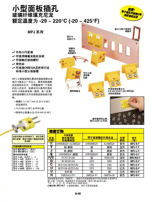
小型面板插孔
玻璃纤维填充尼龙
额定温度为 -29 ~ 220°C (-20 ~ 425°F)
U 外形小巧紧凑
U 可使用弹簧夹轻松安装U 可接触式接线螺钉U 带色标U 可连接OMEGA 及所有行业 标准小型公连接器
K 型母连接器。
MPJ 小型面板插孔要求的面板面积比标准尺寸版本小一半以上。
要将连接器固定在矩形开孔中,只需要使用一个简单的压入式夹子,或者也可以使用可选的MSS 卡装条来安装一整排。
成一定角度的接线螺钉允许在面板组装后进行接G-45
免
费! 每个插孔均附
赠I D 号
标签和防尘罩
在技术进步允许的条件下,我们不断MPJ 系列
可与小型 连接器 匹配
图片为 实际尺寸。
随附弹簧夹
图片为易于使用的
弹簧夹
弹簧夹
随附在 连接器中
可连接直径最大为
0.8 mm (0.03") (20 AWG)的 多股或单股线。
OmniSeal®圣戈班能密封圈弹簧蓄圣戈班集团总部,法国Les Miroirs美国加利福尼亚州GardenGrove比利时Kontich中国上海闵行波兰Kolo日本Suwa德国Willich巴西Vinhedo过去的可靠证明...弹簧蓄能系统压力弹簧蓄能工作条件下的OmniSeal®400A密封圈密封圈夹套材料用在密封夹套上圣戈班F l u o r o l o y®复合材料由高性能聚合物树脂制成,此类树脂经过复合加工之后可在各种密封环境中获得最佳性能。
以下为我们最常推荐使用的合成物,并适用于大多数情况。
多年来,圣戈班密封圈已经开发了500多种用于各种独特密封应用的密封材料,我们仍将继续不断配置和开发新型材料。
材料代码颜色说明及推荐用途温度范围摩擦系数磨损系数*拉伸强度(psi/MPa)延伸率(%)硬度(邵氏D)°F°CA01白色纯P TF E。
特别适合用于轻型到中等动态服务以及静态应用。
有限的耐磨损和耐热性。
低气体渗透率。
良好的低温特性。
中等到极端的真空应用。
符合FDA标准要求。
-346 至+500-210 至+2600.097,5004,000(27.6)30058A02白色改性P TF E。
特别适合用于轻型到中等动态和静态应用。
有限的耐磨损和耐热性。
低气体渗透率。
良好的低温特性。
中等到极端的真空应用。
符合FDA标准要求较高的抗蠕变和抗咬合性能。
-346 至+572-210 至+3000.096,0004,800(33.1)45058A05黑色聚合物填充P TF E。
在高温高压和高转速下具有卓越的耐磨性。
特别适合用于水和水基溶液。
在干燥或恶劣润滑条件下表现较好。
对软金属有研磨作用。
-346 至+572-210 至+3000.0912,000(13.8)17064A08棕褐色聚合物填充P TF E。
卓越的耐热性和耐磨性。
无研磨性。
建议用于软金属上的中速到高速动态应用。
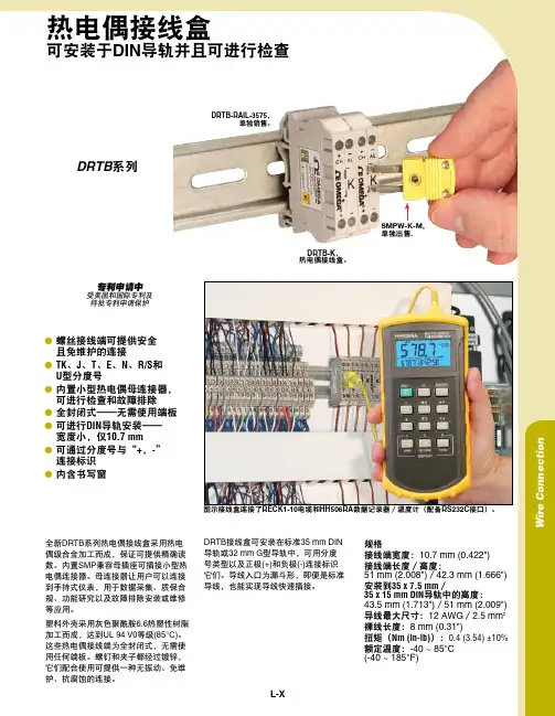
热电偶接线盒可安装于DIN 导轨并且可进行检查图示接线盒连接了RECK1-10电缆和HH506RA 数据记录器/温度计(配备RS232C 接口)。
DRTB 系列全新DRTB 系列热电偶接线盒采用热电偶级合金加工而成,保证可提供精确读数。
内置SMP 兼容母插座可插接小型热电偶连接器。
母连接器让用户可以连接到手持式仪表,用于数据采集、质保合规、功能研究以及故障排除安装或维修等应用。
塑料外壳采用灰色聚酰胺6.6热塑性树脂加工而成,达到UL 94 V0等级(85°C)。
这些热电偶接线端为全封闭式,无需使用任何端板。
螺钉和夹子都经过镀锌,它们配合使用可提供一种无振动、免维护、抗腐蚀的连接。
规格接线端宽度:10.7 mm (0.422")接线端长度/高度:51 mm (2.008")/42.3 mm (1.666")安装到35 x 7.5 mm /35 x 15 mm DIN 导轨中的高度: 43.5 mm (1.713")/51 mm (2.009")导线最大尺寸:12 AWG /2.5 mm 2裸线长度:8 mm (0.31")扭矩(Nm (in-lb)):0.4 (3.54) ±10%额定温度:-40 ~ 85°C (-40 ~ 185°F)DRTB-K , 热电偶接线盒。
DRTB-RAIL-3575,单独销售。
受美国和国际专利及待批专利申请保护专利申请中DRTB 接线盒可安装在标准35 mm DIN 导轨或32 mm G 型导轨中,可用分度号类型以及正极(+)和负极(-)连接标识它们。
导线入口为漏斗形,即便是标准导线,也能实现导线快速插接。
W i r e C o n n e c t i o nL-Xl 螺丝接线端可提供安全 且免维护的连接lT K 、J 、T 、E 、N 、R/S 和 U 型分度号l 内置小型热电偶母连接器,可进行检查和故障排除l 全封闭式——无需使用端板l可进行DIN 导轨安装—— 宽度小,仅10.7 mm l可通过分度号与“+,-” 连接标识l 内含书写窗SMPW-K-M, 单独出售.2配件订购示例:DDRTB-K ,K 型热电偶接线盒,可安装于DIN 导轨,配备RECK1-10,K 型0.3 m (1')可伸缩延长电缆。
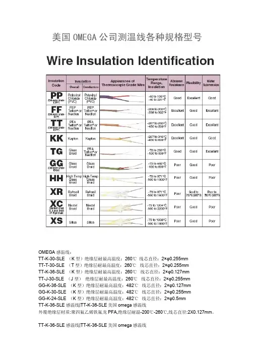
美国OMEGA公司测温线各种规格型号OMEGA感温线:TT-K-30-SLE (K型)绝缘层耐最高温度:260℃线芯直径:2×φ0.255mmTT-T-30-SLE (T型)绝缘层耐最高温度:260℃线芯直径:2×φ0.255mmTT-K-36-SLE (K型)绝缘层耐最高温度:260℃线芯直径:2×φ0.127mmTT-J-30-SLE (J型)绝缘层耐最高温度:260℃线芯直径:2×φ0.255mmGG-K-36-SLE (K型)绝缘层耐最高温度:482℃线芯直径:2×φ0.127mmGG-K-30-SLE (K型)绝缘层耐最高温度:482℃线芯直径:2×φ0.255mmGG-K-24-SLE (K型)绝缘层耐最高温度:482℃线芯直径:2×φ0.5mmTT-K-36-SLE感温线|TT-K-36-SLE美国omega感温线外覆绝缘层材质:聚四氟乙烯铁氟龙PFA,绝缘层耐温-200℃-260℃,线芯直径:2X0.127mm。
TT-K-36-SLE感温线|TT-K-36-SLE美国omega感温线图片仅供参考,以实物为准外覆绝缘层分析:种类适用温度不燃性耐磨性耐油性耐酸性耐湿性可绕性PFA铁氟龙-267至260度良优优优优良TT-K-36-SLE感温线|TT-K-36-SLE美国omega感温线详细参数分度号K型外覆绝缘层材质聚四氟乙烯铁氟龙PFA外敷绝缘层耐温-200℃-260℃线芯材质镍-铬合金/镍铝合金线芯直径2X0.127m线芯绝缘层标记红为负极/黄为正极线长度每卷1000英尺/305米。
可按客户需要剪断,焊接,加插头或绕线轴零售用途此TT-K-36-SLE感温线可适合任何K型进口及国产的温度记录仪表使用另有更多OMEGA感温线的型号:TT-K-24SLE、TT-K-30SLE、TT-K-36SLE、GG-K-24SLE、GG-K-30SLE-GG-K-36SLE、HH-K-24SLE、GG-J-30SLE、TT-J-30SLE、TT-T-30SLE、SMPW-K-F、SMPW-J-F、SMPW-T-F等等。

连接器常用材质及性能介绍1、连接器绝缘体常用材质通常有:PBT、NYLON、ABS、PC、LCP等材料,但原则上采用耐燃性较佳之材质。
a.PBT料:一般常用PBT料加20-30%玻璃纤维,具有抗裂防冲击、防电能力,其耐磨性好,磨擦系数较低,自身润滑效果好,耐油耐化学药品性好。
在高温高湿下伋有很好的介电强度。
其缩水率0.6%-3.0%之间,其耐温为230℃左右。
成型性好,具耐燃性。
其为连接器产品常用胶料。
b.NYLON66、NYLON6T、PC、LCP料:其缩水率1.0%-0.3%,耐温比PBT高,常用NYLON66耐温260℃--280℃,NYLON6T 耐温280℃--300℃,LCP耐温290℃--320℃。
但其吸水性较大,一般用于耐高温与PITCH 较少的产品(如SMD、HOUSING、PLCC等产品)C.ABS料:具有良好抗冲击韧性、耐油性、耐磨性、容易成型、硬质性好、刚性好,耐温100℃左右,一般用于连接器中辅助产品上。
2、注塑成形常见之缺陷及其原因常见成型缺陷有以下几种:塑件有黑斑或黑液、表面不光洁、溢料、塑料成形不完整、气泡或烧焦、瘪形、拼缝线或塑件紧缩在模具内等等缺陷。
其主要原因分三部分:注塑机之因素、模具之因素、胶料之因素。
3、连接器接触件组成及性能接合体材质:插头用金属接合体材质,一般原则上以黄铜为主,但特别要求插拔次数极高,且长寿命期限时磷青铜,铍铜等弈可采用。
以下对目前行业上铜材种类及性作介绍1.黄铜---铜及锌之合金,共颜色因锌之含量而异。
a.黄铜-----含锌25~35%者,最适常温加工。
b.黄铜-----含锡35%~45%者,最适常温加工,市面上贩卖之铜板,铜棒均属之。
2.青铜----铜及锡之合金,其颜色因锡之含量而异。
一般广义之称呼除黄铜以外之铜合金称为青铜。
磷青铜-----在青铜中加以磷,耐摩性有之,但磷过多,则铸造困难,其成分为锡8~12%,磷0.5~1.5%.接触件材料选用接触件可用几种合金中的任何一种材料制成,具体选择则要根据接触件的类型,插拔的频度以及连接器所工作的电气条件和环境条件而定。
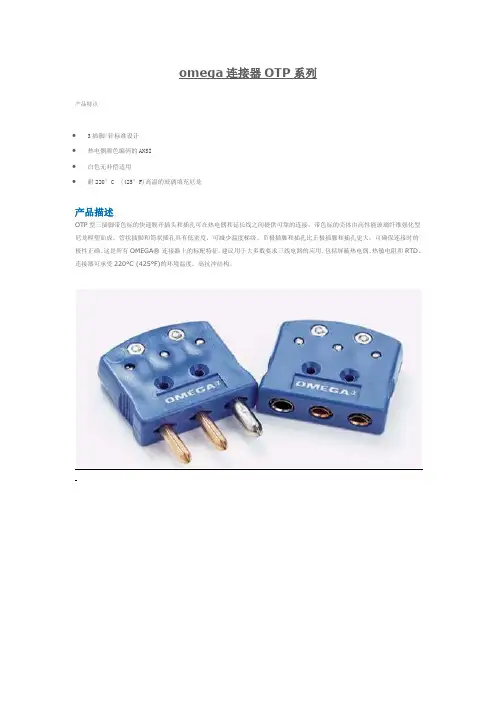
omega连接器OTP系列
产品特点
∙3插脚/针标准设计
∙热电偶颜色编码的ANSI
∙白色无补偿适用
∙耐220°C (425°F)高温的玻璃填充尼龙
产品描述
OTP型三插脚带色标的快速脱开插头和插孔可在热电偶和延长线之间提供可靠的连接。
带色标的壳体由高性能玻璃纤维强化型尼龙模塑而成。
管状插脚和筒状插孔具有低密度,可减少温度梯级。
负极插脚和插孔比正极插脚和插孔更大,可确保连接时的极性正确。
这是所有OMEGA® 连接器上的标配特征。
建议用于大多数要求三线电路的应用,包括屏蔽热电偶、热敏电阻和RTD。
连接器可承受220°C (425°F)的环境温度。
高抗冲结构。
e-mail:**************User’s GuidePT SERIESElectrical ConnectorsTwist Lock TypeShop online atIntroductionThe OMEGA ®PT Series Connectors are miniature, quick-disconnect and environment-resisting, designed for operation between -55 and 125°C (-67 and 257°F). Solder contacts are provided. Designed to accommodate both power and signal circuitry, these connectors are available in a great variety of sizes and contact configurations. Solder type contact connectors are pressure-tight and immersion proof. Crimp contact connectors provide a pressure tight seal when mated. Refer to Table 1.Table 1Features• Rugged Aluminum Shells • Rated to 125°C (257°F)• Strain Relief Cable Clamp • Secure Solder Contacts • #20 AWG Wire Size• High Conductivity Gold Plated ContactsPin AssignmentsNo. of Part No.ContactsPT01F8-4P4PT01F10-6P 6PT06F8-4S 4PT06F10-6S62SpecificationsInsulation Resistance at 25°C:5000 megohms min.(77°F)Voltage Drop:#20 contact, #20 wire, at 7.5 A, 55 mV max.Air Pressure:30 psi at -55°C (-67°F)Water Immersion: 1.8 m (6'), 48 hoursDurability:500 cycles of coupling and uncoupling Shells:Aluminum alloy, 0.0003 cadmium plate with olive drab chromate Insulators:NeopreneContacts:High conductivity copper alloy, 0.000050 gold over copper Dimensions:See Figure 1MaleFemaleFigure 1. Dimensions for PT01F and PT06F3M0262/0902It is the policy of OMEGA Engineering, Inc. to comply with all worldwide safety and EMC/EMI regulations that apply. OMEGA is constantly pursuing certification of its products to the European New Approach Directives. OMEGA will add the CE mark to every appropriate device upon certification.The information contained in this document is believed to be correct, but OMEGA accepts no liability for any errors it contains, and reserves the right to alter specifications without notice.WARNING: These products are not designed for use in, and should not be used for, human applications.Direct all warranty and repair requests/inquiries to the OMEGA Customer Service Department. BEFORE RET URNING ANY PRODUCT (S) T O OMEGA, PURCHASER MUST OBT AIN AN AUT HORIZED RET URN (AR) NUMBER FROM OMEGA’S CUST OMER SERVICE DEPART MENT (IN ORDER T O AVOID PROCESSING DELAYS). T he assigned AR number should then be marked on the outside of the return package and on any correspondence.The purchaser is responsible for shipping charges, freight, insurance and proper packaging to prevent breakage in transit. FOR WARRANTY RETURNS, please have the following informa-tion available BEFORE contacting OMEGA:1.Purchase Order number under which the product was PURCHASED,2.Model and serial number of the product under warranty, and3.Repair instructions and/or specific problems relative to theproduct.FOR NON-WARRANTY REPAIRS,consult OMEGA for cur-rent repair charges. Have the following information avail-able BEFORE contacting OMEGA:1. Purchase Order number to cover the COST of the repair,2.Model and serial number of the product, and3.Repair instructions and/or specific problems relative to the product.OMEGA’s policy is to make running changes, not model changes, whenever an improvement is possible. This affords our customers the latest in technology and engineering.OMEGA is a registered trademark of OMEGA ENGINEERING, INC.© Copyright 2006 OMEGA ENGINEERING, INC. All rights reserved. T his document may not be copied, photocopied, reproduced, translated, or reduced to any electronic medium or machine-readable form, in whole or in part, without the prior written consent of OMEGA ENGINEERING, INC.Servicing North America:U.S.A.:One Omega Drive, Box 4047ISO 9001 Certified Stamford, CT 06907-0047Tel: (203) 359-1660FAX: (203) 359-7700e-mail:**************Canada:976 BergarLaval (Quebec) H7L 5A1, Canada Tel: (514) 856-6928FAX: (514) 856-6886e-mail:*************For immediate technical or application assistance:U.S.A. andSales Service: 1-800-826-6342/1-800-TC-OMEGA Canada:Customer Service: 1-800-622-2378/1-800-622-BEST Engineering Service: 1-800-872-9436/1-800-USA-WHEN Mexico:En Espan ˜ol: (001) 203-359-7803e-mail:*****************FAX: (001) 203-359-7807**************.mxServicing Europe:Czech Frystatska 184, 733 01 Karviná, Czech Republic Republic:TEL: +420 (0)59 6311899FAX: +420 (0)59 6311114Tol Free: 0800-1-66342e-mail:*****************Germany/Daimlerstrasse 26, D-75392 Deckenpfronn, Germany Austria:Tel: +49 (0)7056 9398-0FAX: +49 (0)7056 9398-29TollFreeinGermany************e-mail:*************United One Omega Drive, River Bend Technology Centre Kingdom:Northbank, Irlam, ManchesterISO 9002 Certified M44 5BD United KingdomTel: +44 (0)161 777 6611FAX: +44 (0)161 777 6622Toll Free in United Kingdom: 0800-488-488e-mail:**************.uk。
A-157** 填上焊结点类型:G (接地),E (外露),U (非接地)。
导线长度超过2 m (80"),则需每300 mm (12")收取额外费用,并修改型号。
订购示例:TC-K-NPT-G-72,管塞式K 型接地端热电偶,带 1⁄4 NPT 螺纹和72"延长导线。
TC-K-NPT-U-72,管塞探头带有非接地端、裸端导线和不锈钢编织护套,图片为实际尺寸。
TC-(*)-NPT 系列坚固耐用的管塞式 热电偶探头
弹簧耐扭电缆固定装置防止电缆“扭坏”。
TC-K-1/8NPT-U-72-DUAL ,双感温元件管
单感温元件热电偶。
U 坚固的304不锈钢外壳,配有耐扭电缆固定弹簧
U 可选单感温元件和双感温元件U 1⁄4 或 1⁄8 NPT 安装螺纹U 2
m (80") 玻璃纤维编织层外裹不锈钢编织护套的导线U 20 AWG ,1⁄4 NPT 24 AWG 的尺寸是绞合的,1⁄8 NPT 编织护套绞合——耐磨、 抗剪、柔韧
U 环境温度条件下可以承受 2500 psi 压力
U 接地端和非接地端探头是容器、压力舱和管线应用的 理想之选
U 外露端设计用于空气温度测量和气流监测U 标配裸端导线,可选SMPW 连接器U 可选择J 、K 、T 或E 型热电偶U 接地、非接地或外露端U 特殊定制设计,具有多种NPT 螺纹,尖端直径或尖端长度可
选择
U 平端探头可供选择,请咨询定制产品工程部门U 探头温度范围可达650°C (1200°F)U 过渡接插件/线缆温度范围达480°C (900°F)标配裸端导线。
尼龙加玻纤标准
尼龙加玻璃纤维是一种常见的复合材料,广泛应用于汽车、电子、建筑和航空航天等领域。
其制造和应用需要遵循一些标准,以保证产品的质量和安全性。
尼龙加玻璃纤维的制造应符合国际标准ISO 1043-1,ISO 1874-1和ASTM D4066。
其中,ISO 1043-1规定了塑料材料的命名和缩写方法;ISO 1874-1规定了尼龙的物理和机械性能的测量方法;ASTM D4066规定了塑料材料的分类和标记方法。
在应用领域方面,汽车行业应遵循SAE J1639和J1887标准,电子行业应遵循UL 94V-0标准,建筑行业应遵循ASTM E84标准,航空航天行业应遵循MIL-I-25537和MIL-I-24768标准。
这些标准规定了尼龙加玻璃纤维在特定领域内的性能和安全要求,以确保其可靠性和持久性。
总之,尼龙加玻璃纤维的制造和应用需要遵循一些标准,以确保其质量和安全性。
各行业应根据自身领域的需要选择适合的标准进行生产和检测。
- 1 -。
SRFGA-106/2SRFGA-624/2SRFGA-218/2-P SRFGA-411/2SRFRA-6/10-P SRFGA-110/10-P SRFGA-305/10-23SRFGA-306/2-P SRFGA-307/2-PSRFRA/SRFGAFlexable Silicone Rubber HeatersDESCRIPTIONSilicone Rubber Fiberglass Insulated Heaters can improve heat transfer and speed warm-ups where controlled heating is required in confined areas. Two circuit designs are available: etched foil or wire wound. Heaters with etched foil designed elements are available where the lengthor width dimension is less than254 mm (10"). All other heaters where both the length and the width dimensions exceed 254 mm (10") use the wire-wound element design. Effect of wattage density (at 115V): gentle warming is best done with2.5 W/in2. A good all-purpose unit is the 5 W/in2. Rapid warm-up and high temperature are achieved with the10 W/in2; however, temperature must be controlled as the safe maximum operating temperature limit of232°C (450°F).Two general styles are covered in this manual. Round silicone rubber heaters and rectangular silicone rubber heaters. All part numbers and total wattage for each heater are listed in specification sheet of SRFRA/ SRFGA Series.ROUND SILICONE RUBBER HEATERSStyles are available from 3 to 12" diameters. The part number scheme is as follows:• SRFRA-[ ]/* for those heaters with-out the pressure sensitive adhesive.• SRFRA-[ ]/*-P for those heaters with the pressure sensitive adhesive. Where [ ] is the diameter of the heater and * is the watt density.NOTES: Heaters with pressure sensitive adhesive are not available at 10 W/in2. Maximum operating temperature is 149ºC (300º F). Examples:6" round heater with 2.5 W/in2 wattage density, without pressure sensitive adhesive has the part number SRFRA-6/2. wattage density, with pressuresensitive adhesive has the partnumber SRFRA-8/5-P.RECTANGULAR SILICONERUBBER HEATERSStyles are available from 1" widthby 1" length to 12" width by 48"length. More specifically, the lengthvaries from the smallest widthdimension increasing by 1 inch to12", and jumps to 18", 24", 30",36", 42", and 48".NOTES: Some sizes of heatersdo not come in all lengths listedabove. For details, refer to TheSpecification sheet of SRFRA/SRFGA Series lists the totalwattage for each heater. The partnumber scheme is as follows:• SRFRGA-[X) []/* for thoseheaters without the pressuresensitive adhesive.• SRFRGA-[X] [ ]/*-P for thoseheaters with the pressure sensitiveadhesive.where [X] is the width of theheater, [ ] is the length of theheater, and * is the watt density.NOTES: Heaters with pressuresensitive adhesive are notavailable at 10 W/in2.The maximum operatingtemperature is 149ºC (300ºF).Examples:Smallest heater 1" wide x 5" longwith a wattage density of 10 W/in2and no pressure sensitiveadhesive (not available in 2.5 W/in2or 5 W/in2) has the part number ofSRFGA-105/10.1" W x 48" L heater with 5 W/in2wattage density with pressuresensitive adhesive has the partnumber of SRFG-148/5-P.2" W x 8" L heater with 10 W/in2wattage density without pressuresensitive adhesive has the partnumber of SRFG-208/10.2sensitive adhesive has the partnumber of SRFGA-642/2-P.INSTALLATION ANDOPERATION CAUTION!Use a method of temperaturecontrol (e.g., thermostat,thermocouple and temperaturecontroller, or variable voltagetransformer) to prevent heatersfrom exceeding maximumoperating temperature ratings.Place temperature sensor closeenough to the heater to senseheater temperature.1. D O NOT immerse heaters inliquids.2. D O NOT operate heaters at avoltage higher than the specifiedor rated voltage.Heaters CAN be operated at therated voltage of 115 VAC or lower.In order to determine the actualwattage developed at appliedvoltages lower than the ratedvoltage, use the following formula:P A= P R x V A2V R2where: PR = rated wattage; PA =actual wattage; VR = rated voltageand VA = actual voltage3. DO NOT cut, punch holes in orotherwise mishandle heaters.4. AVOID exposing heaters tochemicals, acids, alkalies, oils,fluids or other substances thatcould ignite or cause damage tothe heater.5. DO NOT insulate heaters unlessadequate measures are taken tocontrol heater temperature.6. DO NOT leave heater operatingunattended unless adequatecontrols are installed to insuresafety.7. Heaters can be bent aroundcurved surfaces; however,DO NOT exceed minimumbending radius.8. Exercise care in attaching heaters to flat or curved surfaces. Heaters can be attached by mechanicalclamping, by using factory applied pressure sensitive adhesive (PSA), or with a thin layer of RTV. Makesure that the entire heater is in contact with the surface with no air pockets trappedunderneath. This is especially important for high watt density heaters, i.e., heaters with a watt density of 10 watts/square inch, to prevent heater failure. DO NOT overlap heaters.9. Heaters must be attached to an appropriate heat sink and should NOT be mounted free standing in air.10. Make sure heaters are installed and used by qualified personnel. DO NOT attempt to repair damaged heaters.SPECIFICATIONSHEATING ELEMENT DESIGN: etched foil designed elements are available where the length or width dimension is less than 254 mm (10"). All other heaters are wire wound.MAXIMUM OPERATINGTEMPERATURE: Heaters with-out Pressure Sensitive Adhesive (PSA), 232°C (450°F). Heaters with Pressure Sensitive Adhesive (PSA), 120°C (250°F). VOLTAGE: 115 VoltsWATT DENSITY: 2.5, 5 or 10 watts/in2WATTAGE: 5 to 1440 wattsPRESSURE SENSITIVEADHESIVE (PSA): optional, not available at 10 watts/square inch watt densityLEAD WIRE: 305 mm (12") UL1180 PTFE Insulated DIELECTRIC STRENGTH: 1250 VACMINIMUM BENDING RADIUS: 2.00" typicalHEATER THICKNESS:0.040", except at lead wire exit (thickness varies with heater) DIMENSIONS: Refer to the other.***********************The information contained in this document is believed to be correct, but OMEGA accepts no liability for any errors it contains, and reserves the right to alter specifications without notice.Servicing North America:U.S.A.Omega Engineering, Inc.Headquarters: 800 Connecticut Ave. Suite 5N01, Norwalk, CT. 06854Toll-Free: 1-800-826-6342 (USA & Canada only)Customer Service: 1-800-622-2378 (USA & Canada only) Engineering Service: 1-800-872-9436 (USA & Canada only) Tel: (203) 359-1660 Fax: (203) 359-7700 e-mail:**************For Other Locations Visit /worldwideWARRANTY/DISCLAIMEROMEGA ENGINEERING, INC. warrants this unit to be free of defects in materials and workmanship for a period of 13 months from date of purchase. OMEGA’s WARRANT Y adds an additional one (1) month grace period to the normal one (1) year product warranty to cover handling and shipping time. This ensures that OMEGA’s customers receive maximum coverage on each product.If the unit malfunctions, it must be returned to the factory for evaluation. OMEGA’s Customer Service Department will issue an Authorized Return (AR) number immediately upon phone or written request. Upon examination by OMEGA, if the unit is found to be defective, it will be repaired or replaced at no charge. OMEGA’s WARRANTY does not apply to defects resulting from any action of the purchaser, including but not limited to mishandling, improper interfacing, operation outside of design limits, improper repair, or unauthorized modification. This WARRANTY is VOID if the unit shows evidence of having been tampered with or shows evidence of having been damaged as a result of excessive corrosion; or current, heat, moisture or vibration; improper specification; misapplication; misuse or other operating conditions outside of OMEGA’s control. Components in which wear is not warranted, include but are not limited to contact points, fuses, and triacs.OMEGA is pleased to offer suggestions on the use of its various products. However, OMEGA neither assumes responsibility for any omissions or errors nor assumes liability for any damages that result from the use of its products in accordance with information provided by OMEGA, either verbal or written. OMEGA warrants only that the parts manufactured by the company will be as specified and free of defects. OMEGA MAKES NO OTHER W ARRANTIES OR REPRESENTATIONS OF ANY KIND W HATSOEVER, EXPRESSED OR IMPLIED, EXCEPT THAT OF TITLE, AND ALL IMPLIED W ARRANTIES INCLUDING ANY W ARRANTY OF MERCHANTABILITY AND FITNESS FOR A PARTICULAR PURPOSE ARE HEREBY DISCLAIMED. LIMITATION OF LIABILITY: The remedies of purchaser set forth herein are exclusive, and the total liability of OMEGA with respect to this order, whether based on contract, warranty, negligence, indemnification, strict liability or otherwise, shall not exceed the purchase price of the component upon which liability is based. In no event shall OMEGA be liable for consequential, incidental or special damages.CONDITIONS: Equipment sold by OMEGA is not intended to be used, nor shall it be used: (1) as a “Basic Component” under 10 CFR 21 (NRC), used in or with any nuclear installation or activity; or (2) in medical applications or used on humans. Should any Product(s) be used in or with any nuclear installation or activity, medical application, used on humans, or misused in any way, OMEGA assumes no responsibility as set forth in our basic WARRANTY / DISCLAIMER language, and, additionally, purchaser will indemnify OMEGA and hold OMEGA harmless from any liability or damagewhatsoever arising out of the use of the Product(s) in such a manner.RETURN REQUESTS / INQUIRIESDirect all warranty and repair requests/inquiries to the OMEGA Customer Service Department. BEFORE RET URNING ANY PRODUCT(S) TO OMEGA, PURCHASER MUST OBTAIN AN AUTHORIZED RETURN (AR) NUMBER FROM OMEGA’S CUST OMER SERVICE DEPART MENT (IN ORDER T O AVOID PROCESSING DELAYS). T he assigned AR number should then be marked on the outside of the return package and on any correspondence.T he purchaser is responsible for shipping charges, freight, insurance and proper packaging to prevent breakage in transit.FOR WARRANTY RETURNS, please have the following information available BEFORE contacting OMEGA:1. P urchase Order number under which the product was PURCHASED,2. M odel and serial number of the product under warranty, and 3. R epair instructions and/or specific problems relative to the product.FOR NON-WARRANTY REPAIRS, consult OMEGA for current repair charges. Have the following information available BEFORE contacting OMEGA:1. Purchase Order number to cover the COST of the repair,2. Model and serial number of the product, and3. R epair instructions and/or specific problems relative to the product.OMEGA’s policy is to make running changes, not model changes, whenever an improvement is possible. T his affords our customers the latest in technology and engineering. OMEGA is a trademark of OMEGA ENGINEERING, INC.© Copyright 2019 OMEGA ENGINEERING, INC. All rights reserved. This document may not be copied, photocopied, reproduced, translated, or reduced to any electronic medium or machine-readable form, in whole or in part, without the prior written consent of OMEGA ENGINEERING, INC.0VSRFGA-106/2SRFGA-624/2SRFGA-218/2-P SRFGA-411/2SRFRA-6/10-P SRFGA-110/10-P SRFGA-305/10-23SRFGA-306/2-P SRFGA-307/2-P。
热电偶套管
信息参考来源:美国OMEGA工业测量热电偶套管、头部和套管组件
头部和套管配置器
设计用于热电偶和RTD 的头部和套管组件
头部和套管组件- 常规信息
热电偶头部和套管组件的选型以不与过程发生直接接触的工作要求为依据。
金属和塑料保护头
热电偶头可选用各种材料和样式,能够符合大多数恶劣环境应用的需求。
连接头接线端子
用于单双工元件的OMEGA 头部组件接线端子
陶瓷纤维绝缘热电偶元件
高温Nextel 绝缘热电偶元件
头部和套管热电偶元件
用于头部和套管配件的陶瓷珠裸线热电偶元件
PFA 涂层/实心热电偶套管
PFA 可承受恶劣的化学环境,因此此类套管非常适用于腐蚀性工业应用中的某些领域。
热电偶套管
OMEGA 热电偶套管可选用的各种材质包括黄铜(ASTM B-16) 和碳钢(C-1018) 等。
不锈钢OMEGA 热电偶套管可选用的各种材质包括黄铜(ASTM B-16)、碳钢(C-1018)、不锈钢.I.S.I. 304 和A.I.S.I. 316、蒙乃尔合金等。
另外还提供特殊材质的套管。