模具教材注塑成型中文
- 格式:ppt
- 大小:1.91 MB
- 文档页数:10

注塑模具工艺中英文对照资料外文翻译文献附录2Integrated simulation of the injection molding process withstereolithography moldsAbstract Functional parts are needed for design verification testing, field trials, customer evaluation, and production planning. By eliminating multiple steps, the creation of the injection mold directly by a rapid prototyping (RP) process holds the best promise of reducing the time and cost needed to mold low-volume quantities of parts. The potential of this integration of injection molding with RP has been demonstrated many times. What is missing is the fundamental understanding of how the modifications to the mold material and RP manufacturing process impact both the mold design and the injection molding process. In addition, numerical simulation techniques have now become helpful tools of mold designers and process engineers for traditional injection molding. But all current simulation packages for conventional injection molding are no longer applicable to this new type of injection molds, mainly because the property of the mold material changes greatly. In this paper, an integrated approach to accomplish a numerical simulation of injection molding into rapid-prototyped molds is established and a corresponding simulation system is developed. Comparisons with experimental results are employed for verification, which show that the present scheme is well suited to handle RP fabricated stereolithography (SL) molds.Keywords Injection molding Numerical simulation Rapid prototyping1 IntroductionIn injection molding, the polymer melt at high temperature is injected into the mold under high pressure [1]. Thus, the mold material needs to have thermal and mechanical properties capable of withstanding the temperatures and pressures of the molding cycle. The focus of many studies has been to create theinjection mold directly by a rapid prototyping (RP) process. By eliminating multiple steps, this method of tooling holds the best promise of reducing the time and cost needed to createlow-volume quantities of parts in a production material. The potential of integrating injection molding with RP technologies has been demonstrated many times. The properties of RP molds are very different from those of traditional metal molds. The key differences are the properties of thermal conductivity and elastic modulus (rigidity). For example, the polymers used in RP-fabricated stereolithography (SL) molds have a thermal conductivity that is less than one thousandth that of an aluminum tool. In using RP technologies to create molds, the entire mold design and injection-molding process parameters need to be modified and optimized from traditional methodologies due to the completely different tool material. However, there is still not a fundamental understanding of h ow the modifications to the mold tooling method and material impact both the mold design and the injection molding process parameters. One cannot obtain reasonable results by simply changing a few material properties in current models. Also, using traditional approaches when making actual parts may be generating sub-optimal results. So there is a dire need to study the interaction between the rapid tooling (RT) process and material and injection molding, so as to establish the mold design criteria and techniques for an RT-oriented injection molding process.In addition, computer simulation is an effective approach for predicting the quality of molded parts. Commercially available simulation packages of the traditional injection molding process have now become routine tools of the mold designer and process engineer [2]. Unfortunately, current simulation programs for conventional injection molding are no longer applicable to RP molds, because of the dramatically dissimilar tool material. For instance, in using the existing simulation software with aluminum and SL molds and comparing with experimental results, though the simulation values of part distortion are reasonable for the aluminum mold, results are unacceptable, with the error exceeding 50%. The distortion during injection molding is due to shrinkage and warpage of the plastic part, as well as the mold. For ordinarily molds, the main factor is the shrinkage and warpage of the plastic part, which is modeled accurately in current simulations. But for RP molds, the distortion of the mold has potentially more influence, which have been neglected in current models. For instance, [3] used a simple three-step simulation process to consider the mold distortion, which had too much deviation.In this paper, based on the above analysis, a new simulation system for RP molds is developed. The proposed system focuses on predicting part distortion, which is dominating defect in RP-molded parts. The developed simulation can be applied as an evaluation tool for RP mold design and process opti mization. Our simulation system is verified by an experimental example.Although many materials are available for use in RP technologies, we concentrate on usingstereolithography (SL), the original RP technology, to create polymer molds. The SL process uses photopolymer and laser energy to build a part layer by layer. Using SL takes advantage of both the commercial dominance of SL in the RP industry and the subsequent expertise base that has been developed for creating accurate, high-quality parts. Until recently, SL was primarily used to create physical models for visual inspection and form-fit studies with very limited func-tional applications. However, the newer generation stereolithographic photopolymers have improved dimensional, mechanical and thermal properties making it possible to use them for actual functional molds.2 Integrated simulation of the molding process2.1 MethodologyIn order to simulate the use of an SL mold in the injection molding process, an iterative method is proposed. Different software modules have been developed and used to accomplish this task. The main assumption is that temperature and load boundary conditions cause significant distortions in the SL mold. The simulation steps are as follows:1T he part geometry is modeled as a solid model, which is translated to a file readable by the flow analysis package.2Simulate the mold-filling process of the melt into a pho topolymer mold, which will output the resulting temperature and pressure profiles.3Structural analysis is then performed on the photopolymer mold model using the thermal and load boundary conditions obtained from the previous step, which calculates the distortion that the mold undergo during the injection process.4If the distortion of the mold converges, move to the next step. Otherwise, the distorted mold cavity is then modeled (changes in the dimensions of the cavity after distortion), and returns to the second step to simulate the melt injection into the distorted mold.5The shrinkage and warpage simulation of the injection molded part is then applied, which calculates the final distor tions of the molded part.In above simulation flow, there are three basic simulation mod ules.2. 2 Filling simulation of the melt2.2.1 Mathematical modelingIn order to simulate the use of an SL mold in the injection molding process, an iterativemethod is proposed. Different software modules have been developed and used to accomplish this task. The main assumption is that temperature and load boundary conditions cause significant distortions in the SL mold. The simulation steps are as follows:1. The part geometry is modeled as a solid model, which is translated to a file readable by the flow analysis package.2. Simulate the mold-filling process of the melt into a photopolymer mold, which will output the resulting temperature and pressure profiles.3. Structural analysis is then performed on the photopolymer mold model using the thermal and load boundary conditions obtained from the previous step, which calculates the distortion that the mold undergo during the injection process.4. If the distortion of the mold converges, move to the next step. Otherwise, the distorted mold cavity is then modeled (changes in the dimensions of the cavity after distortion), and returns to the second step to simulate the melt injection into the distorted mold.5. The shrinkage and warpage simulation of the injection molded part is then applied, which calculates the final distortions of the molded part.In above simulation flow, there are three basic simulation modules.2.2 Filling simulation of the melt2.2.1 Mathematical modelingComputer simulation techniques have had success in predicting filling behavior in extremely complicated geometries. However, most of the current numerical implementation is based on a hybrid finite-element/finite-difference solution with the middleplane model. The application process of simulation packages based on this model is illustrated in Fig. 2-1. However, unlike the surface/solid model in mold-design CAD systems, the so-called middle-plane (as shown in Fig. 2-1b) is an imaginary arbitrary planar geometry at the middle of the cavity in the gap-wise direction, which should bring about great inconvenience in applications. For example, surface models are commonly used in current RP systems (generally STL file format), so secondary modeling is unavoidable when using simulation packages because the models in the RP and simulation systems are different. Considering these defects, the surface model of the cavity is introduced as datum planes in the simulation, instead of the middle-plane.According to the previous investigations [4–6], fillinggoverning equations for the flow and temperature field can be written as:where x, y are the planar coordinates in the middle-plane, and z is the gap-wise coordinate; u, v,w are the velocity components in the x, y, z directions; u, v are the average whole-gap thicknesses; and η, ρ,CP (T), K(T) represent viscosity, density, specific heat and thermal conductivity of polymer melt, respectively.Fig.2-1 a–d. Schematic procedure of the simulation with middle-plane model. a The 3-D surface model b The middle-plane model c The meshed middle-plane model d The display of the simulation result In addition, boundary conditions in the gap-wise direction can be defined as:where TW is the constant wall temperature (shown in Fig. 2a).Combining Eqs. 1–4 with Eqs. 5–6, it follows that the distributions of the u, v, T, P at z coordinates should be symmetrical, with the mirror axis being z = 0, and consequently the u, v averaged in half-gap thickness is equal to that averaged in wholegap thickness. Based on this characteristic, we can divide the whole cavity into two equal parts in the gap-wise direction, as described by Part I and Part II in Fig. 2b. At the same time, triangular finite elements are generated in the surface(s) of the cavity (at z = 0 in Fig. 2b), instead of the middle-plane (at z = 0 in Fig. 2a). Accordingly, finite-difference increments in the gapwise direction are employed only in the inside of the surface(s) (wall to middle/center-line), which, in Fig. 2b, means from z = 0 to z = b. This is single-sided instead of two-sided with respect to the middle-plane (i.e. from the middle-line to two walls). In addition, the coordinate system is changed from Fig. 2a to Fig. 2b to alter the finite-element/finite-difference scheme, as shown in Fig. 2b. With the above adjustment, governing equations are still Eqs. 1–4. However, the original boundary conditions inthe gapwise direction are rewritten as:Meanwhile, additional boundary conditions must be employed at z = b in order to keep the flows at the juncture of the two parts at the same section coordinate [7]:where subscripts I, II represent the parameters of Part I and Part II, respectively, and Cm-I and Cm-II indicate the moving free melt-fronts of the surfaces of the divided two parts in the filling stage.It should be noted that, unlike conditions Eqs. 7 and 8, ensuring conditions Eqs. 9 and 10 are upheld in numerical implementations becomes more difficult due to the following reasons:1. The surfaces at the same section have been meshed respectively, which leads to a distinctive pattern of finite elements at the same section. Thus, an interpolation operation should be employed for u, v, T, P during the comparison between the two parts at the juncture.2. Because the two parts have respective flow fields with respect to the nodes at point A and point C (as shown in Fig. 2b) at the same section, it is possible to have either both filled or one filled (and one empty). These two cases should be handled separately, averaging the operation for the former, whereas assigning operation for the latter.3. It follows that a small difference between the melt-fronts is permissible. That allowance can be implemented by time allowance control or preferable location allowance control of the melt-front nodes.4. The boundaries of the flow field expand by each melt-front advancement, so it is necessary to check the condition Eq. 10 after each change in the melt-front.5. In view of above-mentioned analysis, the physical parameters at the nodes of the same section should be compared and adjusted, so the information describing finite elements of the same section should be prepared before simulation, that is, the matching operation among the elements should be preformed.Fig. 2a,b. Illustrative of boundary conditions in the gap-wise direction a of the middle-plane model b of thesurface model2.2.2 Numerical implementationPressure field. In modeling viscosity η, which is a function of shear rate, temperature and pressure of melt, the shear-thinning behavior can be well represented by a cross-type model such as:where n corresponds to the power-law index, and τ∗ characterizes the shear stress level of the transition region between the Newtonian and power-law asymptotic limits. In terms of an Arrhenius-type temperature sensitivity and exponential pressure dependence, η0(T, P) can be represented with reasonable accuracy as follows:Equations 11 and 12 constitute a five-constant (n, τ∗, B, Tb, β) representation for viscosity. The shear rate for viscosity calculation is obtained by:Based on the above, we can infer the following filling pressure equation from the governing Eqs. 1–4:where S is calculated by S = b0/(b−z)2η d z. Applying the Galerkin method, the pressure finite-element equation is deduced as:where l_ traverses all elements, including node N, and where I and j represent the local node number in element l_ corresponding to the node number N and N_ in the whole, respectively. The D(l_) ij is calculated as follows:where A(l_) represents triangular finite elements, and L(l_) i is the pressure trial function in finite elements.Temperature field. To determine the temperature profile across the gap, each triangular finite element at the surface is further divided into NZ layers for the finite-difference grid.The left item of the energy equation (Eq. 4) can be expressed as:where TN, j,t represents the temperature of the j layer of node N at time t.The heat conduction item is calculated by:where l traverses all elements, including node N, and i and j represent the local node number in element l corresponding to the node number N and N_ in the whole, respectively.The heat convection item is calculated by:For viscous heat, it follows that:Substituting Eqs. 17–20 into the energy equation (Eq. 4), the temperature equation becomes:2.3 Structural analysis of the moldThe purpose of structural analysis is to predict the deformation occurring in the photopolymer mold due to the thermal and mechanical loads of the filling process. This model is based on a three-dimensional thermoelastic boundary element method (BEM). The BEM is ideally suited for this application because only the deformation of the mold surfaces is of interest. Moreover, the BEM has an advantage over other techniques in that computing effort is not wasted on calculating deformation within the mold.The stresses resulting from the process loads are well within the elastic range of the mold material. Therefore, the mold deformation model is based on a thermoelastic formulation. The thermal and mechanical properties of the mold are assumed to be isotropic and temperature independent.Although the process is cyclic, time-averaged values of temperature and heat flux are used for calculating the mold deformation. Typically, transient temperature variations within a mold have been restricted to regions local to the cavity surface and the nozzle tip [8]. The transients decay sharply with distance from the cavity surface and generally little variation is observed beyond distances as small as 2.5 mm. This suggests that the contribution from the transients to the deformation at the mold block interface is small, and therefore it is reasonable to neglect the transient effects. The steady state temperature field satisfies Laplace’s equation 2T = 0 and the time-averaged boundary conditions. The boundary conditions on the mold surfaces are described in detail by Tang et al. [9]. As for the mechanical boundary conditions, the cavity surface is subjected to the melt pressure, the surfaces of the mold connected to the worktable are fixed in space, and other external surfaces are assumed to be stress free.The derivation of the thermoelastic boundary integral formulation is well known [10]. It is given by:where uk, pk and T are the displacement, traction and temperature,α, ν represent the thermal expansion coefficient and Poisson’s ratio of the material, and r = |y−x|. clk(x) is the surfacecoefficient which depends on the local geometry at x, the orientation of the coordinate frame and Poisson’s ratio for the domain [11]. The fundamental displacement ˜ulk at a point y in the xk direction, in a three-dimensional infinite isotropic elastic domain, results from a unit load concentrated at a point x acting in the xl direction and is of the form:where δlk is the Kronecker delta function and μ is the shear modulus of the mold material.The fundamental traction ˜plk , measured at the point y on a surface with unit normal n, is:Discretizing the surface of the mold into a total of N elements transforms Eq. 22 to:where Γn refers to the n th surface element on the domain.Substituting the appropriate linear shape functions into Eq. 25, the linear boundary element formulation for the mold deformation model is obtained. The equation is applied at each node on the discretized mold surface, thus giving a system of 3N linear equations, where N is the total number of nodes. Each node has eight associated quantities: three components of displacement, three components of traction, a temperature and a heat flux. The steady state thermal model supplies temperature and flux values as known quantities for each node, and of the remaining six quantities, three must be specified. Moreover, the displacement values specified at a certain number of nodes must eliminate the possibility of a rigid-body motion or rigid-body rotation to ensure a non-singular system of equations. The resulting system of equations is assembled into a integrated matrix, which is solved with an iterative solver.2.4 Shrinkage and warpage simulation of the molded partInternal stresses in injection-molded components are the principal cause of shrinkage and warpage. These residual stresses are mainly frozen-in thermal stresses due to inhomogeneous cooling, when surface layers stiffen sooner than the core region, as in free quenching. Based onthe assumption of the linear thermo-elastic and linear thermo-viscoelastic compressible behavior of the polymeric materials, shrinkage and warpage are obtained implicitly using displacement formulations, and the governing equations can be solved numerically using a finite element method.With the basic assumptions of injection molding [12], the components of stress and strain are given by:The deviatoric components of stress and strain, respectively, are given byUsing a similar approach developed by Lee and Rogers [13] for predicting the residual stresses in the tempering of glass, an integral form of the viscoelastic constitutive relationships is used, and the in-plane stresses can be related to the strains by the following equation:Where G1 is the relaxation shear modulus of the material. The dilatational stresses can be related to the strain as follows:Where K is the relaxation bulk modulus of the material, and the definition of α and Θ is:If α(t) = α0, applying Eq. 27 to Eq. 29 results in:Similarly, applying Eq. 31 to Eq. 28 and eliminating strain εxx(z, t) results in:Employing a Laplace transform to Eq. 32, the auxiliary modulus R(ξ) is given by:Using the above constitutive equation (Eq. 33) and simplified forms of the stresses and strains in the mold, the formulation of the residual stress of the injection molded part during the cooling stage is obtain by:Equation 34 can be solved through the application of trapezoidal quadrature. Due to the rapid initial change in the material time, a quasi-numerical procedure is employed for evaluating the integral item. The auxiliary modulus is evaluated numerically by the trapezoidal rule.For warpage analysis, nodal displacements and curvatures for shell elements are expressed as:where [k] is the element stiffness matrix, [Be] is the derivative operator matrix, {d} is the displacements, and {re} is the element load vector which can be evaluated by:The use of a full three-dimensional FEM analysis can achieve accurate warpage results, however, it is cumbersome when the shape of the part is very complicated. In this paper, a twodimensional FEM method, based on shell theory, was used because most injection-molded parts have a sheet-like geometry in which the thickness is much smaller than the other dimensions of the part. Therefore, the part can be regarded as an assembly of flat elements to predict warpage. Each three-node shell element is a combination of a constant strain triangular element (CST) and a discrete Kirchhoff triangular element (DKT), as shown in Fig. 3. Thus, the warpage can be separated into plane-stretching deformation of the CST and plate-bending deformation of the DKT, and correspondingly, the element stiffness matrix to describe warpage can also be divided into the stretching-stiffness matrix and bending-stiffness matrix.Fig. 3a–c. Deformation decomposition of shell element in the local coordinate system. a In-plane stretchingelement b Plate-bending element c Shell element3 Experimental validationTo assess the usefulness of the proposed model and developed program, verification is important. The distortions obtained from the simulation model are compared to the ones from SL injection molding experiments whose data is presented in the literature [8]. A common injection molded part with the dimensions of 36×36×6 mm is considered in the experiment, as shown in Fig. 4. The thickness dimensions of the thin walls and rib are both 1.5 mm; and polypropylene was used as the injection material. The injection machine was a production level ARGURY Hydronica 320-210-750 with the following process parameters: a melt temperature of 250 ◦C; an ambient temperature of 30 ◦C; an injection pressure of 13.79 MPa; an injection time of 3 s; and a cooling time of 48 s. The SL material used, Dupont SOMOSTM 6110 resin, has the ability to resist temperatures of up to 300 ◦C temperatures. As mentioned above, thermal conductivity of the mold is a major factor that differentiates between an SL and a traditional mold. Poor heat transfer in the mold would produce a non-uniform temperature distribution, thus causing warpage that distorts the completed parts. For an SL mold, a longer cycle time would be expected. The method of using a thin shell SL mold backed with a higher thermal conductivity metal (aluminum) was selected to increase thermal conductivity of the SL mold.Fig. 4. Experimental cavity modelFig. 5. A comparison of the distortion variation in the X direction for different thermal conductivity; where “Experimental”, “present”, “three-step”, and “conventional” mean the results of the experimental, the presented simulation, the three-step simulation process and the conventional injection molding simulation, respectively.Fig. 6. Comparison of the distortion variation in the Y direction for different thermal conductivitiesFig. 7. Comparison of the distortion variation in the Z direction for different thermal conductivitiesFig. 8. Comparison of the twist variation for different thermal conductivities For this part, distortion includes the displacements in three directions and the twist (the difference in angle between two initially parallel edges). The validation results are shown in Fig.5 to Fig. 8. These figures also include the distortion values predicted by conventional injection molding simulation and the three-step model reported in [3].4 ConclusionsIn this paper, an integrated model to accomplish the numerical simulation of injection molding into rapid-prototyped molds is established and a corresponding simulation system is developed. For verification, an experiment is also carried out with an RPfabricated SL mold.It is seen that a conventional simulation using current injection molding software breaks down for a photopolymer mold. It is assumed that this is due to the distortion in the mold caused by the temperature and load conditions of injection. The three-step approach also has much deviation. The developed model gives results closer to experimental.Improvement in thermal conductivity of the photopolymer significantly increases part quality. Since the effect of temperature seems to be more dominant than that of pressure (load), an improvement in the thermal conductivity of the photopolymer can improve the part quality significantly.Rapid Prototyping (RP) is a technology makes it possible to manufacture prototypes quickly and inexpensively, regardless of their comp lexity. Rapid Tooling (RT) is the next step in RP’s steady progress and much work is being done to obtain more accurate tools to define the parameters of the process. Existing simulation tools can not provide the researcher with a useful means of studying relative changes. An integrated model, such as the one presented in this paper, is necessary to obtain accurate predictions of the actual quality of final parts. In the future, we expect to see this work expanded to develop simulations program for injection into RP molds manufactured by other RT processes.References1. Wang KK (1980) System approach to injection molding process. Polym-Plast Technol Eng 14(1):75–93.2. Shelesh-Nezhad K, Siores E (1997) Intelligent system for plastic injection molding process design. J Mater Process Technol 63(1–3):458–462.3. Aluru R, Keefe M, Advani S (2001) Simulation of injection molding into rapid-prototyped molds. Rapid Prototyping J 7(1):42–51.4. Shen SF (1984) Simulation of polymeric flows in the injection molding process. Int J Numer Methods Fluids 4(2):171–184.5. Agassant JF, Alles H, Philipon S, Vincent M (1988) Experimental and theoretical study of the injection molding of thermoplastic materials. Polym Eng Sci 28(7):460–468.6. Chiang HH, Hieber CA, Wang KK (1991) A unified simulation of the filling and post-filling stages in injection molding. Part I: formulation. Polym Eng Sci 31(2):116–124.7. Zhou H, Li D (2001) A numerical simulation of the filling stage in injection molding based on a surface model. Adv Polym Technol 20(2):125–131.8. Himasekhar K, Lottey J, Wang KK (1992) CAE of mold cooling in injection molding using a three-dimensional numerical simulation. J EngInd Trans ASME 114(2):213–221.9. Tang LQ, Pochiraju K, Chassapis C, Manoochehri S (1998) Computeraided optimization approach for the design of injection mold cooling systems. J Mech Des, Trans ASME 120(2):165–174.10. Rizzo FJ, Shippy DJ (1977) An advanced boundary integral equation method for three-dimensional thermoelasticity. Int J Numer Methods Eng 11:1753–1768.11. Hartmann F (1980) Computing the C-matrix in non-smooth boundary points. In: New developments in boundary element methods, CML Publications, Southampton, pp 367–379.12. Chen X, Lama YC, Li DQ (2000) Analysis of thermal residual stress in plastic injection molding. J Mater Process Technol 101(1):275–280.13. Lee EH, Rogers TG (1960) Solution of viscoelastic stress analysis problems using measured creep or relaxation function. J Appl Mech 30(1):127–134.14. Li Y (1997) Studies in direct tooling using stereolithography. Dissertation, University of Delaware, Newark, DE..。

(精编)模具注塑术语中英文对照(精编)模具注塑术语中英文对照根据国家标准,以下为部分塑料模具成形术语的标准翻译。
动模MovableMouldMovingHalf定模座板FixedClampPlateTopClampingPlateTopPlate动模座板MovingClampPlateBottomClampingPlateBottomPlate上模座板UpperClampingPlate下模座板LowerClampingPlate凹模固定板Cavity-retainerPlate 型芯固定板MouldCore-retainerPlate凸模固定板Punch-retainerPlate模套DieBodyDieSleeveDieBlank支承板BackingPlateSupportPlate垫块SpacerParallel支架EjectorHousingMouldBaseLeg模头DieHead模具分类8InjectionMold注塑模PlasticRubberMould塑胶模RubberMolding橡胶成形HotChamberDieCasting热室压铸SandMoldCasting砂模铸造ExtrusionMold挤出模Multi-CavityMold多模穴模具PalletizingDie叠层模PlasterMold石膏模ThreePlatesMold三板模PlainDie简易模PierceDie冲孔模FormingDie成型模ProgressiveDie连续模GangDies复合模ShearingDie剪边模CavityDie型腔模RivetingDie铆合模CompressionMolding压缩成型FlashMold溢流式模具ExtrusionMold挤压式模具SplitMold分割式模具MouldCavity型腔母模MoldCore模芯公模LargeDieMold大型模具PreciseDieMold 精密模具ComplexDieMold复杂模具FoamingMould发泡模具MetalDie金属模具PlasticMold塑料模具ToolStampingDiePunchDie冲压模具ExtrusionDie挤压模具GraphiteDie石墨模具流道浇口部分RunnerSystem浇道系统SprueColdMaterialTrap浇道冷料井SpruePuller拉杆RunnerDesign流道设计MainRunner主流道SecondaryRunner 次流道MouldGateDesign浇口设计SubmarineGate潜伏浇口TunnelGate隧道式浇口PinpointGate点浇口FanGate扇形浇口SideGate侧浇口EdgeGate侧缘浇口TabGate 搭接浇口FilmGate薄膜浇口FlashGate闸门浇口SlitGate缝隙浇口DishGate盘形浇口DiaphragmGate隔膜浇口RingGate环形浇口Runnerless无浇道Sprueless无射料管方式LongNozzle延长喷嘴方式Sprue浇口,溶渣Insulated/HotRunner热浇道RunnerPlat 浇道模块ValveGate阀门浇口SlagWell冷料井ColdSlag冷料渣SprueGate射料浇口Nozzle 射嘴SprueLockPin料头钩销(拉料杆)注塑缺陷Flash飞边Warpage翘曲AirTrap积风Blush发赤FlowLine流痕Splay银纹ShortShot 短射SinkMark缩痕Streak条纹Void缩孔WeldLine熔接线GasMark烧焦ColdSlug冷斑Delamination起皮Burr毛刺FlawScratch刮伤Gloss光泽Glazing光滑SurfaceCheck表面裂痕Hesitation迟滞注塑工艺MoldingConditions成型条件Drying烘干BarrelTemperature 料筒温度MeltTemperature熔化温度MoldTemperature模具温度InjectionPressure注塑压力BackPressure背压InjectionSpeed注塑速度ScrewSpeed螺杆转速TensileStrength抗拉强度T ensileElongation延伸率FlexuralModulus弯曲模FlexuralStrength抗弯强度Shrinkage收缩率RegrindUsage次料使用Moulding模塑机械设备Lathe车床Planer刨床Miller/MillingMachine铣床Grinder磨床Driller钻床LinearCutting线切割ElectricalSparkle电火花Welder电焊机PunchingMachine冲床Robot机械手CommonEquipment 常用设备EDMElectronDischargeMachining放电加工3DCoordinateMeasurement三次元量床BoringMachine搪孔机ContouringMachine轮廓锯床CopyGrindingMachine仿形磨床CylindricalGrindingMachine外圆磨床DieSpottingMachine合模机EngravingMachine 雕刻机EngravingE.D.M雕模放置加工机FormGrindingMachine成形磨床GraphiteMachine石墨加工机HorizontalBoringMachine卧式搪孔机HorizontalMachineCenter卧式加工制造中心InternalCylindricalMachine内圆磨床模具零件TopPlate上托板(顶板)T opBlock上垫脚PunchSet上模座PunchPad上垫板PunchHolder上夹板StripperPad脱料背板UpStripper上脱料板MaleDie公模(凸模)FeatureDie公母模FemaleDie母模(凹模)UpperMoldPlate上模板LowerMoldPlate 下模板DiePad下垫板DieHolder下夹板DieSet下模座BottomBlock下垫脚BottomPlate下托板(底板)StrippingPlate内外打(脱料板)OuterStripper外脱料板InnerStripper内脱料板LowerStripper下脱料板InnerGuidingPost 内导柱InnerHexagonScrew内六角螺钉DowelPin固定销MouldCoilSpring模具弹簧LifterPin 顶料销IsoheightSleeve等高套筒Pin销LifterGuidePin浮升导料销GuidePin导正销WireSpring圆线弹簧OuterGuidingPost外导柱StopScrew止付螺丝LocatedPin定位销OuterBush外导套Punch冲头Insert入块(嵌入件)DeburringPunch压毛边冲子GroovePunch压线冲子StampedPunch字模冲子RoundPunch圆冲子SpecialShapePunch 异形冲子BendingBlock折刀Roller滚轴BafflePlate挡块LocatedBlock定位块SupportingBlockforLocation定位支承块AirCushionPlate气垫板Air-CushionEject-rod 气垫顶杆TrimmingPunch切边冲子StiffeningRibPunchStinger加强筋冲子RibbonPunch压筋冲子Reel-stretchPunch卷圆压平冲子GuidePlate定位板SlidingBlock滑块SlidingDowelBlock滑块固定块ActivePlate活动板LowerSlidingPlate 下滑块板UpperHolderBlock上压块UpperMidPlate上中间板SpringBox弹簧箱Spring-BoxEject-rod弹簧箱顶杆Spring-BoxEjec模具技术用语各种常用模具成形方式AccurateDieCasting精密压铸PowderForming粉末成形CalendaringMolding压延成形PowderMetalForging粉末锻造ColdChamberDieCasting冷式压铸PrecisionForging 精密锻造ColdForging冷锻PressForgingstampforging冲锻CompactingMolding粉末压出成形RockingDieForging摇动锻造CompoundMolding复合成形RotaryForging回转锻造CompressionMolding压缩成形RotationalMolding离心成形DipMold浸渍成形RubberMolding橡胶成形EncapsulationMolding注入成形SandMoldCasting砂模铸造ExtrusionMolding挤出成形ShellCasting壳模铸造FoamForming 发泡成形SinterForging烧结锻造ForgingRoll轧锻SixSidesForging 六面锻造GravityCasting重力铸造SlushMolding凝塑成形HollowBlowMolding中空(吹出)成形SqueezeCasting高压铸造HotChamberDieCasting热室压铸Swaging挤锻HotForging 热锻TransferMolding转送成形InjectionMolding射出成形WarmForging温锻InvestmentCasting精密铸造MatchedDieMethod对模成形法LaminatingMethod被覆淋膜成形LowPressureCasting低压铸造LostWaxCasting脱蜡铸造MatchedMouldThermalForming对模热成形模CloseMold合模Demould脱模脱模剂MouldUnloading开模ToolChangeRetoolingDieChanging换模MouldClamping锁模各式模具分类用语BismuthMold铋铸模LandedPlungerMold有肩柱塞式模具BurnishingDie挤光模LandedPositiveMold有肩全压式模具ButtonDie镶入式圆形凹模LoadingShoeMold料套式模具Center-GatedMold中心浇口式模具LooseDetailMold活零件模具ChillMold冷硬用铸模LooseMold活动式模具ColdHobbing冷挤压制模法LouveringDie百叶窗冲切模CompositeDies复合模具ManifoldDie分歧管模具CounterPunch反凸模ModularMold组合模具DoubleStackMold双层模具Multi-CavityMold多模穴模具ElectroformedMold电铸成形模Multi-GateMold复式浇口模具ExpanderDie扩径模OffsetColdBendingDie双折冷弯模具ExtrusionDie挤出模PalletizingDie叠层模FamilyMold反套制品模具PlasterMold石膏模BlankThroughDies漏件式落料模PorousMold通气性模具DuplicatedCavityPlate复板模PositiveMold全压式模具FantailDie扇尾形模具PressureDie压紧模FishtailDie鱼尾形模具ProfileDie轮廓模FlashMold溢料式模具ProgressiveDie顺序模GypsumMold石膏铸模PortableMold手提式模具Hot-RunnerMold热流道模具PrototypeMold雏形试验模具原型模具IngotMold钢锭模PunchingDie落料模LancingDie切口模切缝模Raising(Embossing)压花起伏成形Re-entrantMold倒角式模具SectionalDie拼合模RunlessInjectionMold无流道冷料模具SectionalDie对合模具SegmentMold组合模Semi-PositiveMold半全压式模具Shaper 定型模套SingleCavityMold单腔模具SolidForgingDie整体锻模SplitForgingDie拼合锻模SplitMold双并式模具SpruelessMold无注道残料模具SqueezingDie挤压模StretchFormDie拉伸成形模SweepingMold 平刮铸模SwingDie振动模具ThreePlatesMold三片式模具TrimmingDie切边模UnitMold单元式模具UniversalMold 通用模具UnscrewingMold退扣式模具YokeTypeDie轭型模t-Plate弹簧箱顶板BushingBlockLinerBushing衬套CoverPlate盖板GuidePad导料块模具厂常用之标准零配件AirVentValve通气阀AnchorPin锚梢AngularPin角梢Baffle调节阻板AngularPin倾斜梢BafflePlate折流档板BallButton球塞套BallPlunger定位球塞BallSlider球塞滑块BinderPlate压板BlankHolder防皱压板BlankingDie落料冲头Bolster上下模板Bottomboard浇注底板Bolster垫板BottomPlate下固定板Bracket托架BumperBlock 缓冲块Buster堵口CastingLadle浇注包Castinglug铸耳Cavity模穴(模仁)CavityRetainerPlate模穴托板CenterPin中心梢ClampingBlock 锁定块CoilSpring螺旋弹簧ColdPunchedNut冷冲螺母CoolingSpiral螺旋冷却栓Core心型CorePin心型梢Cotter开口梢Cross十字接头CushionPin缓冲梢DiaphragmGate盘形浇口DieApproach模头料道DieBed型底DieBlock块形模体DieBody铸模座DieBush合模衬套DieButton冲模母模DieClamper夹模器DieFastener模具固定用零DieHolder母模固定板DieLip模唇DiePlate冲模板DieSet冲压模座DirectGate直接浇口DogChuck爪牙夹头Dowel定位梢DowelHole导套孔DowelPin合模梢Dozzle辅助浇口DowelPin定位梢Draft拔模锥度DrawBead张力调整杆DriveBearing传动轴承EjectionPad顶出衬垫Ejector脱模器EjectorGuidePin顶出导梢EjectorLeaderBush顶出导梢衬套EjectorPad顶出垫EjectorPin 顶出梢EjectorPlate顶出板EjectorRod顶出杆EjectorSleeve顶出衬套EjectorValve顶出阀EyeBolt环首螺栓FillingCore填充型芯椿入蕊FilmGate薄膜形浇口FingerPin指形梢FinishMachinedPlate 角形模板FinishMachinedRoundPlate圆形模板FixedBolsterPlate固定侧模板FlangedPin带凸缘针FlashGate毛边形浇口Flask上箱FloatingPunch浮动冲头Gate浇口GateLand浇口面Gib凹形拉紧楔GooseNeck鹅颈管GuideBushing引导衬套GuidePin导梢GuidePost 引导柱GuidePlate导板GuideRail导轨HeadPunch顶头冲孔HeadlessPunch直柄冲头HeavilyT aperedSolid整体模蕊盒HoseNippler管接头ImpactDamper缓冲器InjectionRam压射柱InlayBush嵌入衬套InnerPlunger内柱塞InnerPunch内冲头Insert 嵌件InsertPin嵌件梢KingPin转向梢KingPinBush主梢衬套KnockoutBar脱模杵Land 合模平坦面LandArea合模面LeaderBush导梢衬套LiftingPin起模顶针起模杆Lining内衬LocatingCenterPunch定位中心冲头LocatingPilotPin定位导梢LocatingRing定位环LockBlock压块LockingBlock定位块LockingPlate定位板LooseBush活动衬套MakingDie打印冲子ManifoldBlock歧管档块MasterPlate靠模样板MatchPlate分型板MoldBase塑胶模座MoldClamp铸模紧固夹MoldPlaten模用板MovingBolster换模保持装置MovingBolsterPlate可动侧模板OnePieceCasting整体铸件ParallelBlock平行垫块PartingLine 分模线PartingLockSet合模定位器PassGuide穴型导板PeenedHeadPunch镶入式冲头锤击强化冲头钻杆凸模PilotPin定位销导向销子PinGate针尖浇口Plate衬板PreExtrusionPunch顶挤冲头Punch冲头Puncher推杆PusherPin衬套梢Rack机架RappingRod起模杆Re-entrantMold凹入模RetainerPin嵌件梢RetainerPlate托料板ReturnPin回位梢RidingStripper浮动脱模器RingGate环型浇口Roller滚筒Runner流道RunnerEjectorSet流道顶出器RunnerLockPin流道拉梢ScrewPlug头塞SetScrew固定螺丝Shedder脱模装置Shim分隔片Shoe模座之上下模板Shoot流道ShoulderBolt肩部螺丝Skeleton骨架SlagRiser冒渣口Slide(SlideCore)滑块SlipJoint滑配接头SpacerBlock间隔块SpacerRing间隔环Spider模蕊支架Spindle主轴Sprue注道SprueBushing注道衬套SprueBushingGuide注道导套SprueLockBushing注道定位衬套SpruePuller注道拉料浇道推出杆注道残料顶销SpewLine合模线SquareKey方键SquareNut方螺帽SquareThread方螺纹LimitStopCollar限位套StopPin止动梢StopRing止动环Stopper定位停止梢StraightPin圆柱销StripperBolt脱料螺栓StripperBushing脱模衬套StripperPlate剥料板StrokeEndBlock行程止梢SubmarineGate潜入式浇口SupportPillar支撑支柱顶出支柱SupportPin支撑梢SupportingPlate托板SweepT emplate造模刮板TabGate辅助浇口TaperKey推拔键TaperPin拔锥梢锥形梢TeemingPouring浇注ThreeStartScrew 三条螺纹ThrustPin推力销TieBar拉杵TunnelGate隧道形浇口Vent通气孔WortlePlate拉丝模板模具常用之工作机械3DCoordinateMeasurement三次元量床BoringMachine搪孔机CNCMillingMachineCNC铣床ContouringMachine轮廓锯床CopyGrindingMachine仿形磨床CopyLathe仿形车床CopyMillingMachine仿形铣床CopyShapingMachine仿形刨床CylindricalGrindingMachine外圆磨床DieSpottingMachine合模机DrillingMachine钻孔机EngravingMachine雕刻机EngravingE.D.M 雕模放置加工机FormGrindingMachine成形磨床GraphiteMachine 石墨加工机HorizontalBoringMachine卧式搪孔机HorizontalMachineCenter卧式加工制造中心InternalCylindricalMachine内圆磨床JigBoringMachine冶具搪孔机JigGrindingMachine冶具磨床LapMachine研磨机MachineCenter加工制造中心MultiModelMiller靠磨铣床NCDrillingMachineNC钻床NCGrindingMachineNC磨床NCLatheNC车床NCProgrammingSystemNC程式制作系统Planer 龙门刨床ProfileGrindingMachine投影磨床ProjectionGrinder投影磨床RadialDrillingMachine旋臂钻床Shaper牛头刨床SurfaceGrinder平面磨床TryMachine试模机TurretLathe转塔车床UniversalToolGrindingMachine万能工具磨床VerticalMachineCenter立式加工制造中心WireE.D.M线割放电加工机入水Gate进入位GateLocation水口形式GateType大水口EdgeGate细水口Pin-pointGate水口大小GateSize转水口SwitchingRunnerGate唧嘴口径SprueDiameter流道MoldRunner热流道HotRunnerHotManifold温度控制器温控器ThermostatThermoregulatorsT emperatureController 热嘴冷流道HotSprueColdRunner 唧嘴直流DirectSprueGate圆形流道RoundFullHalfRunner流道电脑分析MoldFlowAnalysis流道平衡RunnerBalance热嘴HotSprue热流道板HotManifold发热管CartridgeHeater探针Thermocouples插头ConnectorPlug插座ConnectorSocket密封封料Seal运水WaterLine喉塞LinePlugThroatT aps喉管Tube塑胶管PlasticTube快速接头JiffyQuickConnectorQuickDisconnectCoupling 模具零件MoldComponents三板模3-PlateMold二板模2-PlateMold边钉导边LeaderPinGuidePin边司导套BushingGuideBushing中托司ShoulderGuideBushing中托边GuidePin顶针板EjectorRetainnerPlate托板SupportPlate螺丝Screw管钉DowelPin开模槽PlyBarScot内模管位CoreCavityinter-Lock顶针EjectorPin司筒EjectorSleeve司筒针EjectorPin推板EjectPlatePushPlateStripperPlate缩呵MovableCoreReturnCorePuller 扣机(尼龙拉勾)NylonLatchLock 斜顶Lifter模胚(架)MoldBase上内模CavityInsert下内模CoreInsert行位(滑块)Slide镶件Insert压座Wedge耐磨板油板WedgeWearPlate压条Plate撑头SupportPillar唧嘴SprueBushing挡板StopPlate定位圈LocatingRing锁扣Latch扣机PartingLockSet推杆PushBar栓打螺丝S.H.S.B顶板EjectorPlate活动臂LeverArm分流锥SprueSpreader分流板SpreaderPlate水口司Bush垃圾钉StopPin隔片Buffle弹弓柱SpringRod弹弓DieSpring中托司EjectorGuideBush中托边EjectorGuidePin镶针Pin销子DowelPin波子弹弓Ballcatch喉塞PipePlug锁模块LockPlate斜顶AnglefromPin斜顶杆AngleEjectorRod尼龙拉勾PartingLocks活动臂LeverArm复位键提前回杆EarlyReturnBar气阀Valves斜导边AnglePin术语Terms承压平面平衡PartingSurfaceSupportBalance模排气PartingLineVenting回针碰料位ReturnPinandCavityInterference 顶针碰运水WaterLineInterfereswithEjectorPin 料位出上下模PartfromCavith (Core)Side不准用镶件DoNotUse(CoreCavity)Insert 用铍铜做镶件UseBerylliumCopperInsert初步模图设计PreliminaryMoldDesign正式模图设计FinalMoldDesign弹弓压缩量SpringCompressedlength稳定性好GoodStabilityStable强度不够InsufficientRigidity均匀冷却EvenCooling扣模Sticking热膨胀ThermalExpansion公差Tolerance铜公(电极)CopperElectrode AirVentValve通气阀AnchorPin锚梢AngularPin角梢Baffle调节阻板AngularPin倾斜梢BafflePlate折流挡板BallButton球塞套BallPlunger定位球塞BallSlider球塞滑块BinderPlate压板BlankHolder防皱压板BlankingDie落料冲头Bolster上下模板BottomBoard浇注底板Bolster垫板BottomPlate 下固定板Bracket托架BumperBlock缓冲块Buster堵口CastingLadle浇注包CastingLug铸耳Cavity模腔模穴(模仁)CavityRetainerPlate模穴托板CenterPin中心梢ClampingBlock锁定块CoilSpring螺旋弹簧ColdPunchedNut冷冲螺母CoolingSpiral螺旋冷却栓。

资料范本本资料为word版本,可以直接编辑和打印,感谢您的下载模具注塑术语中英文对照地点:__________________时间:__________________说明:本资料适用于约定双方经过谈判,协商而共同承认,共同遵守的责任与义务,仅供参考,文档可直接下载或修改,不需要的部分可直接删除,使用时请详细阅读内容根据国家标准,以下为部分塑料模具成形术语的标准翻译。
# q# [& x+ L, `动模 Movable Mould Moving Half4 E. u* i; o. U2 C. j- Z: H定模座板 Fixed Clamp Plate Top Clamping Plate Top Plate 0 \" s* Q8 W3 _% e] r动模座板 Moving Clamp Plate Bottom Clamping Plate Bottom Plate 9 ]上模座板 Upper Clamping Plate: _% |6 K d0 {8 w下模座板 Lower Clamping Plate 2 X: H: [- i. v0 R3 k1 d6 E凹模固定板 Cavity-retainer Plate 6 m3 o+ A% k. l8 Y" W! P型芯固定板 Mould Core-retainer Plate 0 V; tb凸模固定板 Punch-retainer Plate模套 Die Body Die Sleeve Die Blank. l支承板 Backing Plate Support Plate( I4 b; D& j6 f' r8 n垫块 Spacer Parallel R支架 Ejector Housing Mould Base Leg: p模头Die Head 3 ~% T] L6 d1 D} c模具分类8 a- ]8 V5 ^7 ]6 p m+ V5 J/ q- iInjection Mold 注塑模 Plastic Rubber Mould 塑胶模 4 Rubber Molding 橡胶成形Hot Chamber Die Casting 热室压铸 : Sand Mold Casting 砂模铸造Extrusion Mold 挤出模 #Multi-Cavity Mold 多模穴模具Palletizing Die 叠层模Plaster Mold 石膏模 Three Plates Mold 三板模 Plain Die 简易模 Pierce Die 冲孔模Forming Die 成型模 Progressive Die 连续模Gang Dies 复合模 Shearing Die 剪边模) Cavity Die 型腔模Riveting Die 铆合模 Compression Molding 压缩成型 " Flash Mold 溢流式模具Extrusion Mold 挤压式模具 .Split Mold 分割式模具 Mould Cavity 型腔母模 $Mold Core 模芯公模 Large Die Mold 大型模具, Precise Die Mold 精密模具Complex Die Mold 复杂模具) a! t: n2 p/ O-s a7 qFoaming Mould 发泡模具Metal Die 金属模具9Plastic Mold 塑料模具 Tool Stamping Die Punch Die 冲压模具9 l; ]( [! X; i5 h* LExtrusion Die 挤压模具 Graphite Die 石墨模具' h& n) b1 H% z- c流道浇口部分4 e9 ` c: `# T. X1 {3 p+ f8 FRunner System 浇道系统Sprue Cold Material Trap 浇道冷料井Sprue Puller 拉杆Runner Design 流道设计 & _$ G. i+ X1 I2 I! k5 X; vMain Runner 主流道Secondary Runner 次流道 tMould Gate Design 浇口设计Submarine Gate 潜伏浇口 3 P( L( r' E5 I& y6 w8 @Tunnel Gate 隧道式浇口 Pinpoint Gate 点浇口 , Fan Gate 扇形浇口Side Gate 侧浇口 4 j+ z3 v2 @: w. F' eEdge Gate 侧缘浇口Tab Gate 搭接浇口Film Gate 薄膜浇口Flash Gate 闸门浇口 ! r6 w+ w. @( @7 v- N% y! r8 `Slit Gate 缝隙浇口Dish Gate 盘形浇口 'Diaphragm Gate 隔膜浇口Ring Gate 环形浇口 Runnerless 无浇道Sprueless 无射料管方式Long Nozzle延长喷嘴方式Sprue 浇口,溶渣 9Insulated/ Hot Runner 热浇道 Runner Plat 浇道模块 ; Valve Gate阀门浇口 Slag Well冷料井 % V% @, i# J" m9 C' [Cold Slag 冷料渣Sprue Gate 射料浇口Nozzle 射嘴Sprue Lock Pin 料头钩销(拉料杆)注塑缺陷: x, a! ~8 U+ s+ zFlash 飞边 ) E9 V/ I5 E+ a& V9 oWarpage 翘曲8Air Trap 积风 - I) P! H$ @4 K# }Blush 发赤 $Flow Line 流痕 , S!U$ m# V, i& b; c% M$ gSplay 银纹 9 ~8 Z/ J! M. E( J$ Short Shot 短射(Sink Mark 缩痕 !Streak 条纹m: p( K- t5 |: c# E$ Y: KVoid 缩孔$Weld Line 熔接线 : w$ x8 |/ W! s1 m5 p; XGas Mark 烧焦 5 w6 P' U/ H8 h+ @/ |Cold Slug 冷斑 $Delamination 起皮 5 {, y* z" U% d' c, C% Y$ sBurr 毛刺 8 m+ x; d. x8 ? h. @* zFlaw Scratch 刮伤 - n2 ~* G* J3 {5 ZGloss 光泽3 c# s. z5 M% }0 C6 i- H4 s$ N" F6 eGlazing 光滑 8 N8 A4 s; x& z2 E; K; HSurface Check 表面裂痕Hesitation 迟滞. q; S; g; )2 I ) 注塑工艺$ c- Y$ F* Q. L# ~6 X2 ]* {* p( qMolding Conditions 成型条件Drying 烘干 * Z8 S1 p N4 \) }' L" y- HBarrel Temperature 料筒温度( B8 p: n) \: \+ f5 I2 YMelt Temperature 熔化温度4 W: b1 V; r2 |1 ) M ^2 X$ qMold Temperature 模具温度Injection Pressure 注塑压力Back Pressure 背压 5Injection Speed 注塑速度 ( j9 Screw Speed 螺杆转速 ' {% B& }+ `, zTensile Strength 抗拉强度Tensile Elongation 延伸率 /Flexural Modulus 弯曲模FlexuralStrength 抗弯强度Shrinkage 收缩率 9 t9 D2 J; M2 s7 ~( h4 U9 ?/ lRegrind Usage 次料使用Moulding 模塑机械设备8 [) C, u3 q5 OLathe 车床 9 M) f* H% u1 k3 d3 WPlaner 刨床 5 h.H' O/ O7 p1 ~Miller / Milling Machine 铣床 Grinder 磨床 Driller 钻床$ [# J* V$ l9 c$ U0 b: g: NLinear Cutting 线切割Electrical Sparkle电火花 , Welder 电焊机 Punching Machine 冲床 ! s) ]+ ]) t2 L3 n0 g: R. C0 LRobot 机械手 2 J" c0 e" ~+ \Common Equipment 常用设备 - `( [$ i*i8 _' k9 e- T8 ]$ N* hEDM Electron Discharge Machining 放电加工3D Coordinate Measurement 三次元量床 Boring Machine 搪孔机5 A: ?; r# i: d @Contouring Machine 轮廓锯床Copy Grinding Machine 仿形磨床 !N( e2 K, e4 K& P' Cylindrical Grinding Machine 外圆磨床 8 |' m8 g, X9 O; t0 G- O& r) hDie Spotting Machine 合模机Engraving Machine 雕刻机}+ L# L: d) IEngraving E.D.M 雕模放置加工机) O( P# l/ L. ^* x5j A" m- }! HForm Grinding Machine 成形磨床 Graphite Machine 石墨加工机 * hHorizontal Boring Machine 卧式搪孔机 8Horizontal Machine Center 卧式加工制造中心 + |# j x* F0 A; t2 F, LInternalCylindrical Machine 内圆磨床. W" e& c, B0 {模具零件* ]0 S9 G) fTop Plate 上托板(顶板) 2 r6 E* [5 N% R6 ?9 o! B- p& TTop Block 上垫脚 : k4 _1 J. r* f; }. L$ lPunch Set 上模座 2 v1 a) G+ ]# j% PPunch Pad 上垫板 0Punch Holder 上夹板 Stripper Pad 脱料背板 * t; ~/U2 {; gUp Stripper 上脱料板}/ s2 l9 R! m1 vMale Die 公模(凸模)Feature Die 公母模 / @6 _4 _$ l( E: ?% ^! x/ Z: OFemale Die 母模(凹模) , `( x6 U$ x' y$ L) j- rUpper Mold Plate 上模板 Lower Mold Plate 下模板 + s: K$ F/ x- q z! q$ J% u5 @Die Pad 下垫板 Die Holder 下夹板# U( l+ m% ~5 F3 uDie Set 下模座 3 L7 E3 b! `- ~- o) ^6 hBottom Block 下垫脚 1 U- z! ~1 x0 x! P" wBottom Plate下托板(底板)Stripping Plate 内外打(脱料板) " q+ EOuter Stripper 外脱料板 9 t3C/ k/ {8 u: A2 D( XInner Stripper 内脱料板Lower Stripper 下脱料板 5`6 Y8 S; ^8 I/ g! G2 h* ]; sInner Guiding Post 内导柱9 S- N! U+ ^6 Q1 l! o$ R, { D6 YInner Hexagon Screw 内六角螺钉Dowel Pin 固定销 7 ~$ Z5 o; S% y* N* q& y. G* AMould Coil Spring 模具弹簧 !Lifter Pin 顶料销 / F+ Isoheight Sleeve 等高套筒 Pin 销 .Lifter Guide Pin 浮升导料销 + o; c) m* d0 n8 l( L ]4 ]Guide Pin 导正销 ) h" C5 F) K, t9 aWire Spring 圆线弹簧# v; R* \! Z2 K5 ~; ]& X% [5 BOuter Guiding Post 外导柱 , u+ b&`- k+ AStop Screw 止付螺丝Located Pin 定位销 0 g) R( q- j4 [ y4O1 C bOuter Bush 外导套 - a0 y+ Q7 p, e'Punch 冲头 Insert 入块(嵌入件)Deburring Punch 压毛边冲子 " j+ u- W/ u! P% zGroove Punch 压线冲子G5 H/ C/ n) {/ P. bStamped Punch 字模冲子 * |0 O/ z) ^+ r; B, pRound Punch 圆冲子 " T8 A' ?$ h4 f3 U# ?# A# [Special Shape Punch 异形冲子 5OBending Block 折刀 Roller 滚轴 # l7 u6 T- |5 I$ Y% l I% nBaffle Plate 挡块Located Block 定位块 8 l% M4 c# g3 [- [% T2 gSupporting Block for Location 定位支承块 Air Cushion Plate 气垫板Air-Cushion Eject-rod 气垫顶杆Trimming Punch 切边冲子 -Stiffening Rib Punch Stinger 加强筋冲子9 L9 z; ?/ a6 O, s' dRibbon Punch 压筋冲子 Reel-stretch Punch 卷圆压平冲子 'Guide Plate 定位板 / L0 F; r1J/ ) ?Sliding Block 滑块0 M! u% L3 {( T2 h# WSliding Dowel Block滑块固定块 + |2 C) c* F' f, d6 v; YActive Plate 活动板 8 h5 u* S$ a7 JLower Sliding Plate 下滑块板 Upper Holder Block 上压块Upper MidPlate 上中间板Spring Box 弹簧箱 Spring-Box Eject-rod 弹簧箱顶杆Spring-Box Ejec模具技术用语7 D+ l$ ?4 l2 Q各种常用模具成形方式& O+ x; `5 v o- P" KAccurate Die Casting 精密压铸Powder Forming 粉末成形# w: j%_$ i0 ZCalendaring Molding 压延成形 ) @6 I( c" @8 V. h- j9 uPowder Metal Forging 粉末锻造+ R# C! t( I: h" F1 r; sCold Chamber Die Casting 冷式压铸 8 \. d( o/ X+ L+ l3 A" j/ A2 mPrecision Forging 精密锻造"Cold Forging 冷锻 Press Forging stamp forging冲锻6 m$ q. @( ]) C' ZCompacting Molding 粉末压出成形 : Rocking Die Forging 摇动锻造Compound Molding 复合成形 ! N/ q% {1 L, ^) \" GRotary Forging 回转锻造' V9 g( j* }' T$ YCompression Molding 压缩成形 % {( g y7 U" Q8 f4 r+ wRotational Molding 离心成形$ Dip Mold 浸渍成形 2 u( e. c2 L5d( U2 K& IRubber Molding 橡胶成形" q- m4 s9 x9 M; O' oEncapsulation Molding 注入成形 3Sand Mold Casting 砂模铸造Extrusion Molding 挤出成形 Shell Casting 壳模铸造- Foam Forming 发泡成形 ' I5 o, _0 v/ v8 l4 V% t9 vSinter Forging 烧结锻造9 V" _0 B3 f/ s7 J7 O, LForging Roll轧锻Six Sides Forging 六面锻造2 l3 S( W- D) nGravity Casting 重力铸造" l) R/ ]" |, N" D7 Y, HSlush Molding 凝塑成形\% J4 \% c; L1 KHollow Blow Molding 中空(吹出)成形 Squeeze Casting 高压铸造8 P* d( s2 u5 F# F h5 }# BHot Chamber Die Casting 热室压铸 0Swaging 挤锻; j" w" c9 S4 N5 tHot Forging 热锻 ;Transfer Molding 转送成形$ Injection Molding 射出成形 " U3 {- C+ d m/ Warm Forging 温锻- G8 n3 j2 {; O1 KInvestment Casting 精密铸造Matched Die Method 对模成形法* z6 w' w# e" B2 s. Laminating Method 被覆淋膜成形 % m; O9 r( Q( o# d8 z* h( O) cLow Pressure Casting 低压铸造1 ^- z7 `# z, d$ JLost Wax Casting 脱蜡铸造 ; [3VMatched Mould Thermal Forming 对模热成形模8 |9 _7 \- _; Q+ f; K& X/ Z0 Q! bClose Mold 合模 Demould 脱模脱模剂/ O, [9 v% H- B1 DMould Unloading 开模8 Tool Change Retooling Die Changing 换模% Mould Clamping 锁模3 }$ N. {# K: D6 [+ R! C! s) r各式模具分类用语# b' k3 _3 M4 T.i/ U8 @( q1 MBismuth Mold 铋铸模 Landed Plunger Mold 有肩柱塞式模具- b9 M$ o* m( M0 |& x0 LBurnishing Die 挤光模 7 |- f: J" P. w1 S, B' Landed Positive Mold 有肩全压式模具.Button Die 镶入式圆形凹模 ! [% ?9 \$ ]6 n$ BLoading Shoe Mold 料套式模具$ B9 v; I; [4 b* v6 e6 E$ r. CCenter-Gated Mold 中心浇口式模具 .D) g' y" c2 _0 L1 cLoose Detail Mold 活零件模具Chill Mold 冷硬用铸模' D$ C5 m) S }2 t5 l* v+ {+ `; gLoose Mold 活动式模具/ Cold Hobbing 冷挤压制模法 4 @3 N3 w9 |. H7 h& WLouvering Die 百叶窗冲切模7 d+ t: E5 _" F9 e# H; iComposite Dies 复合模具 . t; p" F+ n! w, K8 s3 Q) _Manifold Die 分歧管模具6Counter Punch 反凸模7 S3 R5 J6 R! j7 P$ {Modular Mold 组合模具4Double Stack Mold 双层模具 ! k0 {$ ]8 l/ sMulti-Cavity Mold 多模穴模具% `" E8 g. w/ c Electroformed Mold 电铸成形模 & Multi-Gate Mold 复式浇口模具Expander Die 扩径模% a+ n1 u% E& c1 D# q7 f( G# D" Z AOffset Cold Bending Die 双折冷弯模具' n+ p1 p: Q2 z& ~/ C8 E. w& M1 wExtrusion Die 挤出模 8 IPalletizing Die 叠层模9 i* ^6 G: w% {5 J7 l" D( u) [& w# uFamily Mold 反套制品模具 7 [& G" K, S" Z; uPlaster Mold 石膏模2 I! L! [; B. g" Q2 J4 zBlank Through Dies 漏件式落料模! ?/ A. _* ]. D( pPorous Mold 通气性模具' d: hDuplicated Cavity Plate 复板模 , E& i, ]. d% x3 e( l' ?Positive Mold 全压式模具; g Q1 r/ E5 e* I& M4 s5 }Fantail Die 扇尾形模具 / F, }/ x. X9 `; X& H( R6 h9 x( M& x9 `Pressure Die 压紧模: a7Fishtail Die 鱼尾形模具 ( |$ V) s( t* d9 \Profile Die 轮廓模6 { v: G! E/ J" i8 p9 E5u5 ^4 |Flash Mold 溢料式模具 # H. r6 ^; z0 [7 ]! F2 Q3 WProgressive Die 顺序模9 z: G1 X, O/ oGypsum Mold 石膏铸模 5 y0 _& ~* C/ S% Y7 B4 k! c1 MPortable Mold 手提式模具, r( Y' L/ o4 ]/ Y! u( gHot-Runner Mold 热流道模具 Prototype Mold 雏形试验模具原型模具5 B$ w p: n" ?& iIngot Mold 钢锭模' J* ]1 [6 ^$ T& c9 o, D {; NPunching Die 落料模1 Lancing Die 切口模切缝模2 r6 g4 \' m5 l* T# P, K- ]0 v' WRaising(Embossing)压花起伏成形+ ~7 k) O5 Q0 g1 d% V# ?Re-entrant Mold 倒角式模具 2 `$ k2 A+ I/ z- |# O. ~Sectional Die 拼合模c! \1 N# m: X- sRunless Injection Mold 无流道冷料模具A4 f0 ?8 V+ q l& s8 F% x& kSectional Die 对合模具Segment Mold 组合模 + B: f; T: ^* G4 V* p: i6 ?Semi-Positive Mold 半全压式模具- l9 O& r. k# }% Z$ q$ x' Shaper 定型模套 1 P, I g; F' i6 y! M( ?Single Cavity Mold 单腔模具3 v+ M$ M, a) J) mSolid Forging Die 整体锻模 '~& j, e0 m7 v2 z: Q7 nSplit Forging Die 拼合锻模$ g.Split Mold 双并式模具 * m4 ]6 a& b8 }9 ySprueless Mold 无注道残料模具5 j: d& F! G; Z, k6 i$ pSqueezing Die 挤压模 0 W8 Z' I4 @: P: {4 pStretch Form Die 拉伸成形模4Sweeping Mold 平刮铸模 ; f9 L' \4 D8 r1 G9 c4 d- lSwing Die 振动模具%Three Plates Mold 三片式模具 9 Trimming Die 切边模4Unit Mold 单元式模具 $ Universal Mold 通用模具) Q: H2 d) R, x8 I2 fUnscrewing Mold 退扣式模具 / Q1 K5 \6 t0 ]* E Q4 Y' [6 H% sYoke Type Die 轭型模t-Plate 弹簧箱顶板 # c9 C2 \, R: Q3 I9 A4 rBushing Block Liner Bushing 衬套 , m4 p& y/ Q: x) TCover Plate 盖板 & _2 p6 m# {- hGuide Pad 导料块模具厂常用之标准零配件 I8 p1 L G- S( t1 M: y# )6 lAir Vent Valve 通气阀 $ V, i; S( c0 d xAnchor Pin 锚梢7Angular Pin 角梢 9 _8 `! H5 U+ q2 P3 R8 oBaffle 调节阻板( L, J3 i2l4 B7 ^' N& lAngular Pin 倾斜梢6 r j, m2 u6 ?, T" @- Q. fBaffle Plate 折流档板$ Ball Button球塞套 5 f2 s6 ]4 y8 ~) J, a, r& \! w% EBall Plunger 定位球塞 B w- `; n L$ c/ {3 c2 UBall Slider 球塞滑块 % v3 @+ c: o* fBinder Plate 压板6Blank Holder 防皱压板 . J4 n7 [0 Q& {# _0 B6 N9^Blanking Die 落料冲头. `.Bolster 上下模板m3 B- p% E! V/ c0 DBottom board 浇注底板7Bolster 垫板 $ Bottom Plate 下固定板*Bracket 托架 / ^' u2 K% d6 }# h: L1 Z i6 |Bumper Block 缓冲块: h/ D; \0 ]5 V1 C$ K; A9 Y rBuster 堵口 2 z: ?: Z, {( b* _" k& ACasting Ladle 浇注包4 l* w: G7 U: v! f t: rCastinglug 铸耳 % O. _+ [; x: z3 a; e" `Cavity 模穴(模仁)* e7 |5 n" g$ ], GCavity Retainer Plate 模穴托板 Center Pin 中心梢1 Clamping Block 锁定块2 L7 b+ }1 s2 I7 _" ]- XCoil Spring 螺旋弹簧% Z( r4 }% `- e3 W+ \! U+ HCold Punched Nut 冷冲螺母 !Cooling Spiral 螺旋冷却栓1 Core 心型 3Core Pin 心型梢0 k, X/ o# U8 Z% u Cotter 开口梢 Cross 十字接头 1 Cushion Pin 缓冲梢 8 j' Y* z1 m/ I. W( l( m" G: R: ~Diaphragm Gate 盘形浇口Die Approach 模头料道, d* {3 ^ n8 y3 n$ n4 YDie Bed 型底Die Block 块形模体 . |! O1 U: E% m3 M( wDie Body 铸模座8 |7 V' x1 q* f- [) W! w( r0 dDie Bush合模衬套 ;Die Button 冲模母模3 K, }$ J; K+ qDie Clamper 夹模器 8 T* W4 ~) b% Q: R6 [7f aDie Fastener 模具固定用零Die Holder 母模固定板 * a% @% C/ R, {/ Y1 FDie Lip 模唇: [3 f8 Y- N* q2 V, iDie Plate 冲模板Die Set 冲压模座5 u* q. V8 ?. qDirect Gate 直接浇口Dog Chuck 爪牙夹头$Dowel 定位梢 ,Dowel Hole 导套孔. x+ ]6 W/ x, S/ l9 ?% t, m2 [Dowel Pin 合模梢 3 R8 y7 m5 K" K5 {- nDozzle 辅助浇口)Dowel Pin 定位梢 # Draft 拔模锥度. t. h; F) o# W0 N" l8 oDraw Bead 张力调整杆 6 \, M' z/ Drive Bearing 传动轴承. ]0 \3O% O1 m) D DEjection Pad 顶出衬垫 2 m4 z( v/ T* A+ B KEjector脱模器+ L6 [. V" ^- x/ _$ YEjector Guide Pin 顶出导梢6 p) H; x4 m& M2 Q) H# K$ [Ejector Leader Bush 顶出导梢衬套. EEjector Pad 顶出垫7 Ejector Pin 顶出梢9 K9 E% e% C' kEjector Plate 顶出板) |4 A( C, m7 i) [/ m* u5 }# l$ aEjector Rod 顶出杆9 Ejector Sleeve 顶出衬套[6 t. Y8 f9 X& \Ejector Valve 顶出阀: q# n$ B- o& K4 W7 _$ I/ v" M. P! aEye Bolt 环首螺栓 * c6 T0 w/ c6 M0 Filling Core 填充型芯椿入蕊: Film Gate 薄膜形浇口 / D$ n* l! J' ^9 ^. L% I6 JFinger Pin 指形梢6 Finish Machined Plate 角形模板% Q x2 I0 Q) w5 {Finish Machined Round Plate 圆形模板) s7 d3H/ V$ KFixed Bolster Plate 固定侧模板 , T2 m) T5 x$ t( zFlanged Pin带凸缘针. D( y' J6 E7 {Flash Gate 毛边形浇口 -Flask 上箱Floating Punch 浮动冲头 +Gate 浇口3 _-Gate Land 浇口面9 Q& Y' q8 Y# q7 j. FGib 凹形拉紧楔/ s;Goose Neck 鹅颈管 $ K& Y"r! X8 {/ V1 C3 O$ wGuide Bushing 引导衬套& Guide Pin 导梢 Guide Post 引导柱+ G: Guide Plate 导板 9Guide Rail 导轨, L5 w s6 Z& E2 k3j$ H0 C7 QHead Punch 顶头冲孔}( a: _ Z& Z5 W( |. W9 J+ tHeadless Punch 直柄冲头+ w; ]* L0 P; B2 N$ t(Heavily Tapered Solid整体模蕊盒 2 H# E2 A- {$ E1 u2 H, @Hose Nippler 管接头. Impact Damper 缓冲器 5Injection Ram 压射柱Inlay Bush 嵌入衬套8 W1 |0 }, U+ q;b _+ i" vInner Plunger 内柱塞' ]- P+ {* R0 P8 v% K+ T" `+ YInner Punch 内冲头 # }! G7 a4 [+ _ L) A$ IInsert 嵌件 4 h1 ]3 H( G* T- F: m' m; LInsert Pin 嵌件梢 1 E/ D9 E" l5 R7 c- L6 f1 PKing Pin 转向梢- King Pin Bush 主梢衬套 , s0 |6 g7 w* B' _. rKnockout Bar 脱模杵8 W.B+ {5 \. v( h0 tLand 合模平坦面 #Land Area 合模面1 Q5 r. e& H( b3 fLeader Bush 导梢衬套 6 `+ n3 A) b' S: _Lifting Pin 起模顶针起模杆! J; K9 L K6 P/ [, S" A# lLining 内衬Locating Center Punch 定位中心冲头4 F# m+ s) D' a3 {Locating Pilot Pin 定位导梢 $ x8 P4 ~6 a" x* }9 a# T& n6 sLocating Ring 定位环8Lock Block 压块 3Locking Block 定位块% Y# s) u! E* KLocking Plate 定位板 ; v3 @2 S8 |& } \# P- t'|Loose Bush 活动衬套1 X8 s' C4 _ t5 K' bMaking Die 打印冲子4Manifold Block 歧管档块" Z6 z0 J. F2 G/ u1 O6 lMaster Plate 靠模样板 * ]" S# Q5 z, b1 p0 d: c B, qMatch Plate 分型板1Mold Base 塑胶模座 & Q$ A! ^- f( s' v, w' s% C6 v! I- ~Mold Clamp 铸模紧固夹: L9 k/ H* Y" wMold Platen 模用板p7 l% p: U$ a* e: JMoving Bolster 换模保持装置+ r! o5 @. P7 S4 H `- DMoving Bolster Plate 可动侧模板, r8 u2 q$ O# U2 Z, FOne Piece Casting 整体铸件9 Parallel Block平行垫块 + |Parting Line 分模线6 s% t! x- m& tParting Lock Set 合模定位器Pass Guide 穴型导板- C Y$ R% d8 Y: f( MPeened Head Punch 镶入式冲头锤击强化冲头钻杆凸模' j3 J* r8 N/ g- a( x; y% \Pilot Pin 定位销导向销子6 n8 m9 B; K; c" O& D r; VPin Gate 针尖浇口 # _3 u r" w$ J2 z5 { B4 L0 ^Plate 衬板0 a5 v b0 ?1 I5 _1 e( ]8 ~Pre Extrusion Punch 顶挤冲头5 P1 F2 b. Y& d* b8 \) S, H( UPunch 冲头1 H+ ^6 p( v, b bPuncher 推杆4 Z' I% e, X* g% ]4 R' c/ WPusher Pin 衬套梢 4 x3 {" D+ X S3 c. O# ~Rack 机架 4 u' }) F z6 y& }% |5 g' V- pRapping Rod 起模杆! _4 ^# Z! [# {% X! p C* MRe-entrant Mold 凹入模1 D( N4 D) S& z3 M; n1 | V. qRetainer Pin 嵌件梢& p! l! H+ x8 a( xRetainer Plate 托料板 $ R4 z% x, H4 x0 z6 V0 [- NReturn Pin 回位梢/ Q, g5 s- s/ W# kRiding Stripper 浮动脱模器8 ?4 ?9 t9 p( @) \. z0 Z3 ^6 b7 kRing Gate 环型浇口0 z7 o6 E( d/ j/ r: K" i! R. {Roller 滚筒 " o5 k' z( E3 k. LRunner 流道& z- O4 _* f" g2 x6 xRunner Ejector Set 流道顶出器 + O. F/ `:_( \4 b6 jRunner Lock Pin 流道拉梢8 w$ s! X# m3 I0 \7 yScrew Plug 头塞3 z# l9 G/ |5 i m5 v8 o% PSet Screw 固定螺丝+ N$ X# C7 x" xShedder 脱模装置; I0 C" N* D" e ^ Y; o1 oShim 分隔片/ x) Y1 U' C0 o L/ m Shoe 模座之上下模板" g- O) O# _! ~7 n$ L; w- Q; t7 zShoot 流道1 X0 F( v7 E" |( m" ` Shoulder Bolt 肩部螺丝`2 l- Y& o# j p; X# U+ bSkeleton 骨架. X) T# B# t3 f+ g/ A- q4 `9 DSlag Riser 冒渣口 ' _3 l8 m3 G, v3 g- ySlide(Slide Core)滑块- r* {" r+ l' U v5 fSlip Joint 滑配接头: G8 g7 F) J; o/ ]Spacer Block 间隔块& m0 L/ w: z# q8 s3 q) v: OSpacer Ring 间隔环 ! ^, e/ U6 U$ j4X O1 E8 J% m2 f+ xSpider 模蕊支架; l: a6 i# w1 P" FSpindle 主轴( {4 G' @% B6 u' g3 j/ f3 sSprue 注道2 C$ q B$ d' g4 uSprue Bushing 注道衬套 / i- y- Q/ V$ f8 L; S; ^' VSprue Bushing Guide 注道导套. c5 @# o& T; }Sprue Lock Bushing 注道定位衬套 2 ?* ~5 C, M+ L [Sprue Puller 注道拉料浇道推出杆注道残料顶销; k9 |: U+ k) P! E6 Q( @6 ]Spew Line 合模线 6 T0 P: [' w8 Q JSquare Key 方键& `8 o o8 q/ e7 F* C* iSquare Nut 方螺帽- u* Z7 ~0 S0 @. dSquare Thread 方螺纹* L7 T9 v: E9 ]6 Y2 O3 WLimit Stop Collar 限位套 5 b9 m" ^6 o( \5 k, a- ZStop Pin 止动梢' d ^' w& X; U) _! JStop Ring 止动环 6 m4 b1 p- e6 ~- UStopper 定位停止梢' o; G, @- `" EStraight Pin 圆柱销# G. B: F8 m k6 lStripper Bolt 脱料螺栓2 J0 G/ g& W; p; l2 P" pStripper Bushing 脱模衬套' ), T, o" n' m0 V3 X2 ?Stripper Plate 剥料板& D* {: a0 w%X R2 aStroke End Block 行程止梢- r$ \: Z! @: t+ ^! G% o, } {Submarine Gate 潜入式浇口8 s# Y* E, ~9 R' Q3 oSupport Pillar 支撑支柱顶出支柱 * Z" l6A( @$ N8 )2 BSupport Pin 支撑梢2 F& L9 y1 `# i; k9 oSupporting Plate 托板9 e* y9 r9 ?/ C* e4 JSweep Template 造模刮板5 e} n8 X, J; f$ F# b5 r& hTab Gate 辅助浇口 } } [; [' J1 l" v: PTaper Key 推拔键, k] ^0 A. o# {* p; w @: G. h( s' s0 eTaper Pin 拔锥梢锥形梢& _+ Y) T! m4 u} q& u9 XTeeming Pouring 浇注: t2 c/ ~/ F- ]Three Start Screw 三条螺纹 7 D7 x6 N1 x1 Q% B& RThrust Pin 推力销: z- S0 I ^$ n+ KTie Bar 拉杵 ! S8 _9 g& W9 F$ bTunnel Gate 隧道形浇口- R* M! T& D8 e" T! U+ h7 zVent 通气孔$ S5 s' V0 ~9 hWortle Plate 拉丝模板模具常用之工作机械5 U9 q2 r/ G" J9 o4 n7 _3D Coordinate Measurement 三次元量床0 A+ w* K' ~' Y, `" E; HBoring Machine 搪孔机: g* k1 ?5 r$ e, G1 Y ~CNC Milling Machine CNC铣床# g0 B n& Z# r- W" x3 BContouring Machine 轮廓锯床5 b& J- `6 L! v& ]- ICopy Grinding Machine 仿形磨床* ?! @" s& S' ~5 r9 m! LCopy Lathe 仿形车床, R6 z7 E/ R8 S9 ] n0 eCopy Milling Machine 仿形铣床! |8 ~8 w. _* u3 }5 ICopy Shaping Machine 仿形刨床6 G) ?" V! [& {) NCylindrical Grinding Machine 外圆磨床* f6 [( `8 p: S) [7 CDie Spotting Machine 合模机6 v5 j9 H$ m4 p1 P6 ~Drilling Machine 钻孔机2 Q0 F/ J8 L# \( I. yEngraving Machine 雕刻机! L% j; j9 x9 g* U. H3 MEngraving E.D.M 雕模放置加工机! N- ?+ J( l/ c, y3 \Form Grinding Machine 成形磨床: a1 p' B3 ~5 S: k p, I' GGraphite Machine 石墨加工机! o9 N3 c" N8 X9 dHorizontal Boring Machine 卧式搪孔机5 O! s4 N5 t5 q4 z( [' NHorizontal Machine Center 卧式加工制造中心 - N4 P. g$ H6 y7 P; _Internal Cylindrical Machine 内圆磨床4 N7 I4 ]$ O+ f- Z+ NJig Boring Machine 冶具搪孔机 8 w+ `) y5 c ^- wJig Grinding Machine 冶具磨床: Q, U7 g& Q! Y2 T( r: ?( [4 qLap Machine 研磨机) U' V2 t# g2 T5 _+ p5 @0 YMachine Center 加工制造中心# v, s7 b5 d5 I9 XMulti Model Miller 靠磨铣床 3 w1 P [- ]3 ~' J8 ^5 i. VNC Drilling Machine NC钻床: ^( {# {; x6 b( X* b* ] Z: NNC Grinding Machine NC磨床$ ^3 }9 w2 U+ M6 eNC Lathe NC车床! o) d* ]7 W% h5 [% B3 ^NC Programming System NC程式制作系统# {+ c$ @9 @' a- TPlaner 龙门刨床4 a3 x2 L( |" i' ]" kProfile Grinding Machine 投影磨床5 u) S, Z. q, {0 ]! {& ZProjection Grinder 投影磨床( Z% u+ M/ P7 VRadial Drilling Machine 旋臂钻床1 m- c/ [) }! g4 F$ M* }Shaper 牛头刨床+ `9 B% w7 Y$ y+ X8 Y) u. d8 wSurface Grinder 平面磨床$ P0 K8 I2 ~; _. d& l1 BTry Machine 试模机6 u( ?1 a8 @# v0 T5j$ jTurret Lathe 转塔车床" h; ?' H5 C9 [8 [Universal Tool Grinding Machine 万能工具磨床|- X9 s4 ]+ `Vertical Machine Center 立式加工制造中心+ X( f( e h- j4 H9 l( c9 F- S5 {) kWire E.D.M 线割放电加工机?# A7 n8 c/ c* @: I5 p入水 Gate % D* I+ l; y0 B" H ~+ u' J) I进入位 Gate Location 9 O7 c% a7 l0 J水口形式 Gate Type / h7 @! x/ _ U2 _ t0 u大水口 Edge Gate ) g+ c+ E/ X2 u; a- y细水口 Pin-point Gate % K8 [( g1 p( K& n3 B ~: T水口大小 Gate Size 5 ?* h7 q7 a# v, _转水口 Switching Runner Gate0 j R: I3 ]. G& [1 N; H# p唧嘴口径 Sprue Diameter# |6 k1 ]1 j @+ _流道 Mold Runner , L" y% Z5 N+ [ n- m' H( Y- d热流道 Hot Runner Hot Manifold8 \2 W/ P! D" H4 A0 W' |- d, U. ?8 e2 S温度控制器温控器Thermostat Thermoregulators Temperature Controller% H$ q2 @$ i5 K" S5 I B% f热嘴冷流道 Hot Sprue Cold Runner 9D- ?& H( ]9 j# S! r! D' P, B4 J唧嘴直流 Direct Sprue Gate, [/ U) x. D/ u- c ^: a圆形流道 Round Full Half Runner $ ]/ t.D. v: o& I流道电脑分析 Mold Flow Analysis % N( T, \. K' H% m2 ?流道平衡 Runner Balance5 V5 t) a# M( R7 [+ o0 r: \9 z热嘴 Hot Sprue) N$ _; }$ d, y& p0 ]7 c, W- p热流道板 Hot Manifold & k4 g) C;o# h# d: a& T3 e% X发热管 Cartridge Heater ; P$ f4 I3 G# O& N4 t! D6 `% I探针 Thermocouples2 u1 @ Z: p; `8 B4 L. c- L插头 Connector Plug / J. i2 |7 a7o+ G7 b/ o插座 Connector Socket ! V2 l* {% W- @3 |密封封料 Seal& s% ~3 ?" x: s4 M) d% w5 |运水 Water Line " ^) U2 Y0 B1 Q5 m* s' t9 U喉塞 Line Plug Throat Taps, n5 n5 P* [% B6 n% S E# A喉管 Tube + V% n I2 f% ]2 F' ]+ c; Q1 [& t塑胶管 Plastic Tube ; V% z7 b5 [$ o8 i) r& J快速接头 Jiffy Quick Connector Quick Disconnect Coupling* ^; ?)S9 l: b3 R模具零件 Mold Components 3 V+ N8 j0 E* Y' d* B三板模 3-Plate Mold 3 w( `6 l& Y6 K2 y: `, I二板模 2-Plate Mold, c% I- H& E. t2 |9 K1 z$ M. |8 ?! d; t边钉导边 Leader Pin Guide Pin' s" j3 G/ O2 w$ L边司导套 Bushing Guide Bushing" O5 @8 i: {. m9 j# Y8 W中托司 Shoulder Guide Bushing ( j. k5 ]5 X3 f0 W- V9 h6 w中托边 Guide Pin 1 d; v4 I8 {& Y1 u' @0 J顶针板 Ejector Retainner Plate% \3 b# @- b1 \. Y托板 Support Plate 6 z5 T* ^( u+ s) }/ { c 螺丝 Screw / Y* m/ B' t& p2 I$ P* O) G* [. r管钉 Dowel Pin$ d- ^" v0 c" C+ R/ o6 A. o开模槽 Ply Bar Scot 6 f! u' s4 W1 V0 c内模管位 Core Cavity inter-Lock2 K0 n3 w; {- ^" M# D2 @, N" L& K顶针 Ejector Pin % a, r6 m" [. A2 i/ r0 C, ]司筒 Ejector Sleeve3 g7 R8 Z2 ?: Y司筒针 Ejector Pin ' ~, F: x# j% j* e推板 Eject Plate Push Plate Stripper Plate $ F2 w, z# y- f9 K0 ?, |' r. G缩呵 Movable Core Return Core Puller v+ `4 p& D8 {7 _5 k扣机(尼龙拉勾) Nylon Latch Lock ' W, i1 Y$ ` r( G$ X斜顶 Lifter ! M% v6 @% ^: }, ^$ w- |9 h模胚(架) Mold Base) N& j3 @1 u; z4 X8 ~- [! C上内模 Cavity Insert 0 K/ K* z* T: L9 [) X0 a& Q5 v; p下内模 Core Insert+ t( o( m$ k, _ U$ P* L$ O& R行位(滑块) Slide 8 T1 k4 t$ C+ G2 H; f2 a镶件 Insert/ o9 B3 R8 d# L压座 Wedge2 q3 ?+ E' W) C6 \- u) ^3 M耐磨板油板 Wedge Wear Plate6 f, D, B. b' m( g压条 Plate ) Y+ J# n$ e9 y! o7 _撑头 Support Pillar 0 f0 Z1 @2 @/ X# a5 t( D唧嘴 Sprue Bushing7 e/ G+ ~1 v# A9 F# D* ]挡板 Stop Plate' Q" X% V/ R7 p定位圈 Locating Ring : \# n$ }! g; E2 v3 e7A Y锁扣 Latch 7 A; E" Y0 r9 f' Z Y: X0 [. x扣机 Parting Lock Setz$ v' s/ k: p9 n推杆 Push Bar( s& c3 G- k8 n2 t栓打螺丝 S.H.S.B: ?/ ` Z% r$ M4 L z/ G顶板 Ejector Plate0 E) X& W! ?' u+ n$ Y+ M5 l! H- u活动臂 Lever Arm , ~6 y8 m, w" |分流锥 Sprue Spreader" ^+ A8 K) r' c( c- f6 P分流板 Spreader Plate* F& a `" w* l) S% B- [/ `水口司 Bush : D" ]; k9 ~: K3 i垃圾钉 Stop Pin2 ^# m# C" i& i: u隔片 Buffle8 y1 N# ` E& _/ v* R- @2 @弹弓柱 Spring Rod$ R5 e( _, G/ W3 P弹弓 Die Spring& W) l j6 P, N8 Z2 p$ S. w: z8 o中托司 Ejector Guide Bush 0 M! _! {, V" \) u中托边 Ejector Guide Pin- q# Q+ b" S! C' |' v; u0 x5 _ d镶针 Pin* o/ f9 j( I9 o9 V A! [4 Z销子 Dowel Pin" f& E/ R% ` ~波子弹弓 Ball catch: N0 @! L$ l, W: i: G3 f9 [* \3 h喉塞 Pipe Plug 9 Q8 U9 {2 c/ f+ s3 L5 f* h( |锁模块 Lock Plate9 o4 @3 d: J2 _+ ?& \! }, M斜顶 Angle from Pin* E9 I4 R0 o# V6 C' ]斜顶杆 Angle Ejector Rod 2 F3 w3 c: l( b4 t! X/ U8 Z! I尼龙拉勾 Parting Locks/ E) J& t+ I; s: G" y8 X+ i- p活动臂 Lever Arm/ s0 V' f r4 l, e1 ~& T! g0 b& A复位键提前回杆 Early Return Bar 3 e2 c9 @5 f* O: v+ i2 a气阀 Valves2 o, b% V- M0 s6 Y( J o$ c斜导边 Angle Pin 9 o& w! O/ F) j,Z0 N" t$ z术语 Terms0 \) p' Y4 `( ~! H9 m7 S/ d承压平面平衡 Parting Surface Support Balance * J6 Z9 Q- z, |# K+ a" ^: p模排气 Parting Line Venting % c+ Q5 e8 J0 m; S- ~回针碰料位 Return Pin and Cavity Interference& Z" L& C9 S$ \$ Q! Q0 U- Q顶针碰运水 Water Line Interferes with Ejector Pin4 B! t \1 }8 k料位出上下模 Part from Cavith (Core) Side2 A0 ]9 r4 w: Y$ ~不准用镶件 Do Not Use (Core Cavity) Insert 7 k, ^5 s# ^9 O' y& N用铍铜做镶件 Use Beryllium Copper Insert % I* k) R' E) E* ~4 v8I q- O( q# I初步模图设计 Preliminary Mold Design 0 P# Z9 k7 Z, T3 Z9 J% u0 L 正式模图设计 Final Mold Design- p1 k# ^! N4 c% [( Z `3 q弹弓压缩量 Spring Compressed length9 P& J% P9 A7 R. _* Y" r5 w" ?稳定性好 Good Stability Stable ' K.h) O7 H/ v% @+ t! S强度不够 Insufficient Rigidity $ r5 A, t/ E+ l$ h# f' C均匀冷却 Even Cooling% X! Y( |4 A& `) h( @" P% w1 S0 X3 W2 w扣模 Sticking' D+ I1 L4 ^8 d( o% H. k热膨胀 Thermal Expansion 2 t+ V& h4 m. J: ]7 f$ V, _2 r公差 Tolerance 6 ?7 D" K& Q9 _, ^5 ?6 I% }5 T( l铜公(电极) Copper Electrode, Z; E4 L6 B7 @2 }2 MAir Vent Valve 通气阀$ e( w p/ g# f- P% a( J! o, qAnchor Pin 锚梢. w: K' U; e7 }Angular Pin 角梢 6 k: Q$ ^ [' n# @; \Baffle 调节阻板 6 g! ^7 A, P2 G1 I6 [Angular Pin 倾斜梢% d3 ?2 C3 y/ S8 L' t% w* c/ gBaffle Plate 折流挡板7 F! X: @" G0 V: ~: }1 [Ball Button 球塞套, |! y1 K6 ]9 a* N# C% m) YBall Plunger 定位球塞 3 t1 S- [" N' S0 t" DBall Slider 球塞滑块 7 a2 \; [1 m. x5 H0 S% bBinder Plate 压板5 R+ I, C4 Q8 f. Y6 W' YBlank Holder 防皱压板 * C& _9 ~# X' G9 t6 p4 ~. pBlanking Die 落料冲头5 v% f% @% {/ [Bolster 上下模板% f" b+ S9 ]/ a" g6 ], sBottom Board 浇注底板 1 e" } R+ C2 ]' q$ t" ~Bolster 垫板 : a: P- i; m% E4 ^/ m% G0 CBottom Plate 下固定板 % P* b' v9 S ~Bracket 托架% Z" u1 K6 o. G5 NBumper Block 缓冲块 7 i! r: [' K1 Y+ CBuster 堵口8 N) \' K+ e* q; x5 wCasting Ladle 浇注包: ]3 j. ~* k3 N4 a LCasting Lug 铸耳 , l* Y( V/ L/ Z, I: N$ P Cavity 模腔模穴(模仁) , I- k ?# z8 d" QCavity Retainer Plate 模穴托板0 H N* [* d; s z$ dCenter Pin 中心梢. ?$ n. x% B! o9 A0 O4 bClamping Block 锁定块5 f, F& d: `) I- OCoil Spring 螺旋弹簧2 X1 e+ V, T- u/ y$ t+ H5 sCold Punched Nut 冷冲螺母 & P3 |2 g6 E) [% ?! m5 y% aCooling Spiral 螺旋冷却栓 $ u2 V4 z" h9 E. i2 dCore 心型+ @3 O; l, u8 i9 F: iCore Pin 心型梢 1 W" {& B7 {" s6 |$ sCotter 开口梢 8 r( Q( i2 Q( Q; ]* A0 L" r9 ]Cross 十字接头" w/ {; L9 y6 W' Y. L# X( }6 N. h( WCushion Pin 缓冲梢 1 r. o) w8 z( d' W: P" {* YDiaphragm Gate 盘形浇口 3 Y9 t! z' p4 u1 h, j+ tDie Approach 模头料道 ) H# {6 C9 a+ Q% Q/ r! w: LDie Bed 型底 " x, X0 Q( U# z- X2 J+ a F$ EDie Block 块形模体n' J0 T5 p! L# p% i1 a( ]6 ADie Body 模体$ A4 n3 b; c7 e8 H' W! l$ zDie Body 铸模座{: }# N( g$ o7 {4 | ^Die Bush 合模衬套. `+ q4 L. ^ R. `% P9 A0 L. BDie Button 冲模母模3 J5 _7 H1 [$ x1 C% DDie Clamper 夹模器: a: Z4 }- d5 CDie Fastener 模具固定用零件 0 b2 O3 z& ?& _+ yDie Holder 母模固定板) n- v3 n+ E0 D- J t. n# @ \Die Lip 模唇1 G1 E y, ]/ [. H! gDie Plate 冲模板9 B# f4 w9 t* G+ M) p" ]7 XDie Set 冲压模座 + k5 t3 _8 E3 ^, q6 yDirect Gate 直接浇口 1 W3 j, W! ]: i5 F+ b: C. aDog Chuck 爪牙夹头 ' M. S, w% Z- a$ q9 P。


iml注塑成型原理
IML是In-Mold Labeling的缩写,中文称为模内贴标。
IML注塑
成型技术是将标签材料与注塑产品一起放入模具中,经过注塑成型流程,标签材料与注塑产品完全融合,成为一个整体。
与传统的贴标方
式相比,IML注塑成型技术有许多优点。
其中最主要的优点就是可以消除标签脱落和翘起的问题,使产品
外观更加美观和高档。
IML注塑成型技术还可以节省人力成本和生产时间,因为标签和塑料制品可以同时完成,而且整个生产过程是自动化的。
IML注塑成型技术需要采用特殊的设备和材料。
标签材料需要在
注塑过程中能够承受高温高压,而且具有优良的机械性能和耐腐蚀性能。
注塑机也需要针对IML技术进行特殊的设计和改进,以确保标签
能够完全贴合在注塑产品表面。
IML注塑成型技术已经广泛应用于各种塑料制品制造中,例如家
电用品、食品包装、医疗用品等。
IML注塑成型技术使得产品能够具有更好的质量和外观,为塑料制品的制造和市场销售提供了重要的支持。
中文2985字附录1 中文译文共射注塑成型技术简介和背景注塑挤压成型法是大规模生产塑料制品最卓越的生产工艺。
它是一种非常通用的生产方法。
注塑成型允许生产几何形状非常复杂和几何尺寸非常小的塑料制品。
例如,一次性照相机的外壳就是通过注塑成型的方法生产出来的。
像这一类塑料制品的几何性状经常包括着几条复杂的曲线、筋板、孔洞、圆柱型的凸台和其他一些复杂结构。
到目前为止,为了进一步增强注塑成型法的有效性,扩大其适用范围和增加收益率,注塑成型法的新的应用和改良被不断发展。
共射注塑成型技术(Co-injection Molding)于是开始出现。
现在主要有两种类型的联合注塑成型技术。
第一种被成为双色成型法。
双色成型法的工艺过程是先向模具中注射进一种树脂材料,然后抽回模具的一部分零件(增加型腔空间)或将已成型的制品转入到一个更大的型腔,并使其充分冷却后,注射进第二种树脂材料。
这种技术被用来生产像计算机的按键和汽车的双色尾灯之类的制品。
第二种技术则更为普通,用第二种技术生产出来的制品通常包含不同的肤层材料和芯层材料。
就像我们所熟知的“夹心三明治”一样,因为芯层材料被包围在肤层材料之间。
夹芯成型技术是将两种不同的塑料原料同时或者快速依次通过同一个浇口的有效注塑成型方法。
一种塑料原料用来形成制品的内部结构,另外一种塑料原料组成制品的表面。
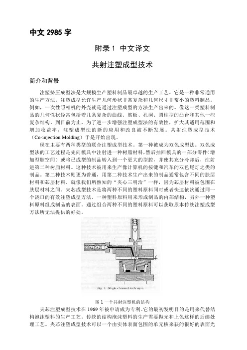
通过组合两种不同的塑料原料可以获取原本传统注塑成型方法所无法提供的好处。
图1一个共射注塑机的结构夹芯注塑成型技术在1969年被申请成为专利。
它的最初发明目的是用来代替结构泡沫塑料的生产工艺。
传统的结构泡沫塑料的生产需要抛光和上色这样的后续处理工艺。
夹芯注塑成型技术可以一个由实体表面包围的单元核来获的很好的表面光滑度。
这项生产工艺在1975年进入商业应用。
夹芯注塑成型生产过程由一台拥有两套彼此独立的注塑控制单元的注塑机来完成。
为了使两种不同的塑料原料在注塑成型过程中通过同一个浇口,必须使用同一个喷嘴和一个转换装置。
模具工业中英文翻译模具常用术语中英文对照局部视图 Partial View冷料# Cold Slag线切割 Wire E.D.M轮廊 Contour螺纹孔 Tapping Hole连接件 Fittings斜针 Angle Pin接合 Engage替换镶件Interchangeable Mold Inserts 指定吨位的注塑机 Specific Press水嘴接头 Water Fittings螺纹 Eyebolt Thread回针 Stop Pin二级顶出针Sub-Leaderd Pin镶件 Mold Insert 加硬 Harden唧嘴 Sprue设计筒图 Design Preliminary名称块表 Title Block版本标识 Revision Level材料清单 Stock List制模 Build Mold手动滑块 Hand Slide漏水测试 Leak Test流道排气 Runner Vents抛光 Draw Polish侧抽芯 Side Action加强筋 Reinforcing三角撑 Gusset柱子 Bossed出模斜度 Draft外廊 Contour落单会议 Kick-Off Meeting装卸孔 Handling Hole运输安全带 Moldstrap码模槽 Clamp Slot撑头 Support Pillar螺牙1/2-13 Eye Bolt 1/2-13Tap 导柱位 Leader Pin Location耐落胶 Teflon Paste偏移量 Offset水塞 Water Line Plug撬模脚 Ppy Slot重新加工 Reworked配件 Components补偿 Compensation平面度 Parallel倒角 Chamfer模胚 Mold Base热嘴 Hotnozzle火花机 Edm熔接线 Weildline压机 Press晒纹 Texturing梯形 Trapezoid凸缘、法兰 Flange方铁 Spacer Block顶针板 Ejector Plate顶针底板 Ejector Retainer Plate垫板 Retainer Plate后模镶针 Core Pin拉圾钉 Stop Pin有托顶针 Shoulder Ejector Pin顶针板导套 Guided Ejection Bushing针板导柱 Guided Ejection Leader Pin唧嘴 Sprue Bushing三板模延伸式唧嘴Extension Nozzle Bushing 水口板导套Runner Stripper Plate Bushing定位圈(法兰) Locating Ring管钉(定位销) Dowel Pin管状管钉 Tubular Dowel吊环 Safety Hoist Ring日期印 Dating Insert环保印 Recycling Insert气顶 Air Poppet Valve截水口镶件 Runner Shut-Off Insert早回 Early Ejector Return加速项 Accelerated Ejector客户 Client 产品名 Part Name产品编号 Part No 缩水 Shrinkage版本 Rev 模胚 Mold Base下模镶件 Core Block上模镶件 Cavity Block小镶件 Sub-Insert下模小镶件 Core Sub-Insert上模小镶件 Cavity Sub-Insert行位 Slide行位镶件 Slide Insert压条 Gib压紧块(铲机) Jaw硬片(摩擦片) Wear Plate水口铁 Runner Bar上模水口铁 Upper Runner Bar下模水口铁 Lower Runner Bar弹簧 Spring水口勾针 Sprue Puller Pin顶针 Ejector Pin撑头 Support Pillar直身锁 Side Lock斜度锁 Interlock锁模板 Safety Bar‘O’令(密封圈) O'Ring喉塞 Plug隔水片 Baffle波子螺丝(行位定位螺丝) Ball-Catch 斜顶 Lifter控制开关 Switch回针 Return Pin斜导柱 Angle Pin推板 Stripper PlateA’板 A'PlateB’板 B'Plate方铁(垫铁)Spacer Block顶针板 Ejector Plate顶针底板 Ejector Retainer Plate垫板 Retainer Plate垃圾钉 Stop Pin有托顶针 Shoulder Ejector Pin顶针板导套 Guided Ejection Bushing针板导柱 Guided Ejection Leader Pin唧嘴 Sprue Bushing三板模延伸式唧嘴Extension Nozzle Bushing 水口板导套Runner Stripper Plate Bushing定位圈(法兰) Locating Ring管钉(定位销) Dowel Pin管状管钉 Tubular Dowel吊环 Safety Hoist Ring日期印 Dating Insert环保印 Recycling Insert气顶 Air Poppet Valve截水口镶件 Runner Shut-Off Insert早回 Early Ejector Return加速顶 Accelerated Ejector扁顶 Blade 出模斜波 Draft手动滑块模具 Hand Slide-In Type Mold回针板 Backup合模 Shutoff空隙槽 Clearance Slot导柱及导套 Leader Pin Bushing水口拉钩 Spuer Puller模框镶件Pocket Insert成型热固性塑胶模具Thermoset Mold 三板模 3-Plat Mold分型面 Parting Line司筒 Ejector Sleeve垫圈 Washer熔接线(夹水纹) Weldline吸针 Sucker Pin回针板 Retainer Plate顶出板 Knock -Out Plate电动安全开关Electrical-Safety Switch 脱开 Cut Of Position预先决定 Preload缓冲器 Bumper衬垫 Cushion公差 Tolerance突然性动作 Slam销针 Dowel钩槽 Gib精磨 Finished通框 Through Window粘后模 Sticking Core粘水口 Sticking Sprue夹水纹 Weld Line变形 Warpage走水不平均 Filling Uneven走不齐 Short Shot挂成品 Part Hanging漏水 Water Leakage刮花(擦伤) Galling漏电 Ele Leakage困气 Air Trapping温度 Temperature注塑模 Injection Mold入水 Gate试板 Sampling压力 Pressure倒圆 Fillet顶棍 Ejector顶白 Stress Mark粘前模 Sticking Cav名称块表 Title Block版本标识 Revision Level材料清单 Stock List斜导柱(斜边) Angle PinA板 A'plateB板 B'plate倒扣 Under-Cut披峰 Flash缩水 Sink Mark氮化 Nitride不规则四边形Trapezoid缩水 Shrinkage连续的 Consecutive雕刻 Engrave出模角 Draft分模面 Parting Surface擦位 Shut-Off(S/0)导套 Bushing回针 Return Pin加硬 Harden唧嘴 Sprue设计筒图 Design Preliminary 丝印 Silkprint不干胶 Adhesive Sticker导向针 Guide Din公差 Tolerance线切割 Wire-Cut电火花 Edm抛光 Polishing蚀纹 Texture探热针 Thermocouple三打螺丝毫(限螺丝) Stripper Bolt 盖板 Cover Plate齿轮 Gear油唧 Hydraulic Cylinder司筒 Ejector Sleeve导柱 Leader Pin冷料# Cold Slag线切割 Wire E.D.M.轮廓 Contour螺纹孔 Tapping Hole连接件 Fittings斜针 Angle Pin接合 Engage替换镶件Interchangeable Mold Inserts 指定吨位的注塑机Specific Press水嘴接头 Water Fittings螺纹 Eyebolt Thread回针 Stop Pin二级顶出针 Sub-Leader Pin镶件 Mold Insert锁定位 Lock楔子(铲鸡) Wedge高产量模量 High V olume Running Mold 剖面图 Cross Section 模具结构 Mold Construction模芯 Parting Core局部视图 Partial View热流道 Manifold热嘴 Hot Nozzle型腔数 Cav No模号 Mold No胶料 Material尺寸 Dimension重要尺寸 Critical Dimension雕刻 EngraveAssembly line组装线Layout布置图Conveyer流水线物料板Rivet table拉钉机Rivet gun拉钉枪Screw driver起子Pneumatic screw driver气动起子worktable 工作桌OOBA开箱检查fit together组装在一起fasten锁紧(螺丝)fixture 夹具(治具)pallet栈板barcode条码barcode scanner条码扫描器fuse together熔合fuse machine热熔机repair修理operator作业员QC品管supervisor 课长ME制造工程师MT制造生技cosmetic inspect外观检查inner parts inspect内部检查thumb screw大头螺丝lbs. inch镑、英寸EMI gasket导电条front plate前板rear plate后板chassis 基座bezel panel面板power button电源按键reset button重置键Hi-pot test of SPS高源高压测试V oltage switch of SPS 电源电压接拉键sheet metal parts 冲件plastic parts塑胶件SOP制造作业程序material check list物料检查表work cell工作间trolley台车carton纸箱sub-line支线left fork叉车personnel resource department 人力资源部production department生产部门planning department企划部QC Section品管科stamping factory冲压厂painting factory烤漆厂molding factory成型厂common equipment常用设备uncoiler and straightener整平机punching machine 冲床robot机械手hydraulic machine油压机lathe车床planer |'plein?|刨床miller铣床grinder磨床linear cutting线切割electrical sparkle电火花welder电焊机staker=reviting machine铆合机position职务president董事长general manager总经理special assistant manager特助factory director厂长department director部长deputy manager | =vice manager副理section supervisor课长deputy section supervisor =vice section superisor 副课长group leader/supervisor组长line supervisor线长assistant manager助理to move, to carry, to handle搬运be put in storage入库pack packing包装to apply oil擦油to file burr 锉毛刺final inspection终检to connect material接料to reverse material 翻料wet station沾湿台Tiana天那水cleaning cloth抹布to load material上料to unload material卸料to return material/stock to退料scraped |'skr?pid|报废scrape ..v.刮;削deficient purchase来料不良manufacture procedure制程deficient manufacturing procedure制程不良oxidation |' ksi'dei?n|氧化scratch刮伤dents压痕defective upsiding down抽芽不良defective to staking铆合不良embedded lump镶块feeding is not in place送料不到位stamping-missing漏冲production capacity生产力education and training教育与训练proposal improvement提案改善spare parts=buffer备件forklift叉车trailer=long vehicle拖板车compound die合模die locker锁模器pressure plate=plate pinch压板bolt螺栓administration/general affairs dept总务部automatic screwdriver电动启子thickness gauge厚薄规gauge(or jig)治具power wire电源线buzzer蜂鸣器defective product label不良标签identifying sheet list标示单location地点present members出席人员subject主题conclusion结论decision items决议事项responsible department负责单位pre-fixed finishing date预定完成日approved by / checked by / prepared by核准/审核/ 承办PCE assembly production schedule sheet PCE组装厂生产排配表model机锺work order工令revision版次remark备注production control confirmation生产确认checked by初审approved by核准department部门stock age analysis sheet 库存货龄分析表on-hand inventory现有库存available material良品可使用obsolete material良品已呆滞to be inspected or reworked 待验或重工total合计cause description原因说明part number/ P/N 料号type形态item/group/class类别quality品质prepared by制表notes说明yearend physical inventory difference analysis sheet 年终盘点差异分析表physical inventory盘点数量physical count quantity帐面数量difference quantity差异量cause analysis原因分析raw materials原料materials物料finished product成品semi-finished product半成品packing materials包材good product/accepted goods/ accepted parts/ good parts 良品defective product/non-good parts不良品disposed goods处理品warehouse/hub仓库on way location在途仓oversea location海外仓spare parts physical inventory list备品盘点清单spare molds location模具备品仓skid/pallet栈板tox machine自铆机wire EDM线割EDM放电机coil stock卷料sheet stock片料tolerance工差score=groove压线cam block滑块pilot导正筒trim剪外边pierce剪内边drag form压锻差pocket for the punch head挂钩槽slug hole废料孔feature die公母模expansion dwg展开图radius半径shim(wedge)楔子torch-flame cut火焰切割set screw止付螺丝form block折刀stop pin定位销round pierce punch=die button圆冲子shape punch=die insert异形子stock locater block定位块under cut=scrap chopper清角active plate活动板baffle plate挡块cover plate盖板male die公模female die母模groove punch压线冲子air-cushion eject-rod气垫顶杆spring-box eject-plate弹簧箱顶板bushing block衬套insert 入块club car高尔夫球车capability能力parameter参数factor系数phosphate皮膜化成viscosity涂料粘度alkalidipping脱脂main manifold主集流脉bezel斜视规blanking穿落模dejecting顶固模demagnetization去磁;消磁high-speed transmission高速传递heat dissipation热传rack 上料degrease脱脂rinse水洗alkaline etch龄咬desmut剥黑膜D.I. rinse纯水次Chromate铬酸处理Anodize阳性处理seal封孔revision版次part number/P/N料号good products良品scraped products报放心品defective products不良品finished products成品disposed products处理品barcode条码flow chart流程表单assembly组装stamping冲压molding成型spare parts=buffer备品coordinate座标dismantle the die折模auxiliary fuction辅助功能poly-line多义线heater band 加热片thermocouple热电偶sand blasting喷沙grit 砂砾derusting machine除锈机degate打浇口dryer烘干机induction感应induction light感应光response=reaction=interaction感应ram连杆edge finder巡边器concave凸convex凹short射料不足nick缺口speck瑕??shine亮班splay 银纹gas mark焦痕delamination起鳞cold slug冷块blush 导色gouge沟槽;凿槽satin texture段面咬花witness line证示线patent专利grit沙砾granule=peuet=grain细粒grit maker抽粒机cushion缓冲magnalium镁铝合金magnesium镁金metal plate钣金lathe车mill锉plane刨grind磨drill铝boring镗blinster气泡fillet镶;嵌边through-hole form通孔形式voller pin formality滚针形式cam driver铡楔shank摸柄crank shaft曲柄轴augular offset角度偏差velocity速度production tempo生产进度现状torque扭矩spline=the multiple keys花键quenching淬火tempering回火annealing退火carbonization碳化tungsten high speed steel钨高速的moly high speed steel钼高速的organic solvent有机溶剂bracket小磁导liaison联络单volatile挥发性resistance电阻ion离子titrator滴定仪beacon警示灯coolant冷却液crusher破碎机。
目录第一章成型材料第一节注塑成型的进展概述第二节常用塑料第二章注塑材料的有关性能第一节塑料的物理性能第二节聚合物表面性能与相容性第三节聚合物的力学性能第四节聚合物的流变性能第三章制品成型机理第一节结晶效应第二节取向效应第三节内应力第四章成型故障及其解决方法第一节常见故障的产生原因及排除方法第二节聚烯姪类塑料故障的产生原因及排除方法第三节聚丙烯故障的产生原因及排除方法第四节聚氯乙烯故障的产生原因及排除方法第五节苯乙烯类阻燃塑料故障的产生原因及排除方法第六节聚甲醛故障的产生原因及排除方法第七节聚酰胺故障的产生原因及排除方法第八节聚碳酸酯故障的产生原因及排除方法第九节聚苯醴故障的产生原因及排除方法第十节透明塑料故障的产生原因及排除方法第一章成型材料第一节注射成型的进展近年来无论注塑理论和实践方面,还是在注塑工艺和成型设备方面都有较深的研究和进展。
注塑时,首先遇到的是注塑的可成型性,这是衡量塑料能否快速和容易地成型出合乎质量要求的产品。
并希望能在满足质量要求的前提下,以最短注塑周期进行高效率生产。
不同的高分子材料对其加工的工艺条件及设备的性能区别很大,材料性能和工艺条件将最终影响塑料制品的物理机械性能,因此全面了解注塑周期内的工作程序,搞清可成型性和成型工艺条件及各种因素的相互作用和影响,对注塑加工有重要意义。
在对充模压力的影响实验表明:高聚物的非牛顿特性越强,则需要的压越低;结晶型比非结晶型高聚特制品有更大的收缩,在相变中比容变化较大。
在对注塑过程中大分子取向的机理研究证明聚合物熔体受剪切变形时,大分子由无规卷曲状态解开,并向流动方向延伸和有规则的排列,如果熔体很快冷却到相变温度以下,则大分子没有足够的时间松和恢复到它原来的无规则卷曲的构象程度,这时的聚合物就要处于冻结取向状态,这种冻结取向使注塑制品在双折射热传导以及力学性质方面显示出各向导性。
由于流变学和聚合物凝固过程的形变原因,制品取向可能在一个方向占优势形成单轴取向,也可能在两个方向上占优势,形成双轴取向。