RH6015-C(D)_SPEC_Ver1.8
- 格式:pdf
- 大小:380.58 KB
- 文档页数:11
文诚系列技术培训手册清华紫光台式电脑事业部技术支持部2004-06-01目录一、产品特点1.1优良的品质保证1.2出色的结构设计1.3可靠的安全维护二、文诚系列主机配置2.1文诚系列主机配置表三、主板技术规格3.1 精英P6VEMD2主板说明3.2 精英L4S5MG/GX+主板说明3.3 技嘉GA-8I845GV-CH2说明四、驱动程序安装4.1驱动光盘说明4.2驱动程序安装目录一、产品特点文诚系列电脑强调性能价格比,适用于教育、网吧等中低端用户,便于集中管理,统一维护。
1.1优良的品质保证1)通过国家3C认证;2)严格的部件优选体制,所有部件采用业界一线厂商的产品;3)周密的测试全集,保证部件的兼容性,同时保证系统的稳定性;4)五年保修。
1.2出色的结构设计1)立卧两用,根据不同空间随意放置;2)机箱面板模块化设计,根据不同的应用选取不同外观;3)良好的散热设计,确保立卧使用时系统内部热量有效、及时的散发;4)静音设计,减少部件共振,优化风道,降低噪音。
1.3可靠的安全维护1)集成硬盘保护功能,保证硬盘数据的安全,遭到破坏一键恢复;2)同一机型间网络传输功能,维护好一台机器即可通过网络对其他机器进行维护;3)自动维护,无人值班的情况下对整个网络环境中的机器机型维护;4)预留机箱锁孔,防止非法开启机箱。
二、文诚系列主机配置(一)文诚500 文诚800 文诚1000E 文诚1100文诚1200 CPU C3800Celeron 1.8GCeleron 1.8G Celeron 1.8G Celeron 1.8G主板 P6VEMD2L4S5MG/GX+ L4S5MG/GX+ L4S5MG/GX+GA-8I845GV-CH2内存Twinmos 128MDDR333Twinmos 128MDDR333Twinmos 128MDDR333Twinmos 128MDDR333Twinmos 128MDDR333硬盘SeagateST340015ASamsungSV0411N(40GB/5400PRM)SeagateST340015ASamsungSV0411N(40GB/5400PRM)SeagateST340015ASamsungSV0411N(40GB/5400PRM)光驱LG CR-8523B LG GCR-8523B软驱SamsungSFD-321BSamsungSFD-321BSamsungSFD-321B显示卡主板集成主板集成主板集成主板集成主板集成声卡主板集成主板集成主板集成主板集成主板集成网卡主板集成主板集成主板集成主板集成主板集成电源长城 1801-HP 长城 1801-HP 长城 1801-HP 长城 1801-HP 长城 1801-HPCPU风扇主板集成Cool MasterDI4-7H53B/DI4-7H54A-R2Cool MasterDI4-7H53B/DI4-7H54A-R2Cool MasterDI4-7H53B/DI4-7H54A-R2/EC203MBCool MasterDI4-7H53B/DI4-7H54A-R2/EC203MB机箱保利得 EN7472 保利得 EN7472 保利得 EN7472 保利得 EN7472 保利得 EN7472键盘精模 JME7010 精模 JME7010 精模 JME7010 精模 JME7010 精模 JME7010鼠标致伸 M042K0 致伸 M042K0 致伸 M042K0 致伸 M042K0 致伸 M042K0驱动光盘智能驱动光盘V2.0智能驱动光盘V2.0智能驱动光盘V2.0/2.1智能驱动光盘V2.0文诚系列主机配置(二)三、主板技术规格3.1文诚500采用的主板是:精英P6VEMD2,采用VIA CLE266 CE / VT8235 CD 芯片组。
TMS320C6655/57Fixed and Floating-Point Digital Signal Processor Data ManualPRODUCT PREVIEW information applies to products in theformative or design phase of development. Characteristic dataand other specifications are design goals. Texas Instrumentsreserves the right to change or discontinue these productswithout notice.Literature Number:SPRS814March 2012SPRS814—March 2012Data Manual TMS320C6655/57Release HistoryFor detailed revision information, see ‘‘Revision History’’ on page A-226.RevisionDate Description/Comments SPRS841 March 2012Initial releaseFixed and Floating-Point Digital Signal ProcessorSPRS814—March 2012TMS320C6655/ Contents1Features . . . . . . . . . . . . . . . . . . . . . . . . . . . . . . . . . . . . . . . . . . . . . . . . . . . . . . . . . . . . . . . . . . . . . . . . . . . . . . . . . . . . . . . . . . . . . . . . . . . . . . . . .131.1KeyStone Architecture. . . . . . . . . . . . . . . . . . . . . . . . . . . . . . . . . . . . . . . . . . . . . . . . . . . . . . . . . . . . . . . . . . . . . . . . . . . . . . . . . . . . . . . . . . . . . . . . . . . .141.2Device Description . . . . . . . . . . . . . . . . . . . . . . . . . . . . . . . . . . . . . . . . . . . . . . . . . . . . . . . . . . . . . . . . . . . . . . . . . . . . . . . . . . . . . . . . . . . . . . . . . . . . . . .141.3Functional Block Diagram. . . . . . . . . . . . . . . . . . . . . . . . . . . . . . . . . . . . . . . . . . . . . . . . . . . . . . . . . . . . . . . . . . . . . . . . . . . . . . . . . . . . . . . . . . . . . . . . .162Device Overview . . . . . . . . . . . . . . . . . . . . . . . . . . . . . . . . . . . . . . . . . . . . . . . . . . . . . . . . . . . . . . . . . . . . . . . . . . . . . . . . . . . . . . . . . . . . . . . . .172.1Device Characteristics . . . . . . . . . . . . . . . . . . . . . . . . . . . . . . . . . . . . . . . . . . . . . . . . . . . . . . . . . . . . . . . . . . . . . . . . . . . . . . . . . . . . . . . . . . . . . . . . . . . .172.2DSP Core Description. . . . . . . . . . . . . . . . . . . . . . . . . . . . . . . . . . . . . . . . . . . . . . . . . . . . . . . . . . . . . . . . . . . . . . . . . . . . . . . . . . . . . . . . . . . . . . . . . . . . .182.3Memory Map Summary. . . . . . . . . . . . . . . . . . . . . . . . . . . . . . . . . . . . . . . . . . . . . . . . . . . . . . . . . . . . . . . . . . . . . . . . . . . . . . . . . . . . . . . . . . . . . . . . . . .212.4Boot Sequence. . . . . . . . . . . . . . . . . . . . . . . . . . . . . . . . . . . . . . . . . . . . . . . . . . . . . . . . . . . . . . . . . . . . . . . . . . . . . . . . . . . . . . . . . . . . . . . . . . . . . . . . . . .252.5Boot Modes Supported and PLL Settings. . . . . . . . . . . . . . . . . . . . . . . . . . . . . . . . . . . . . . . . . . . . . . . . . . . . . . . . . . . . . . . . . . . . . . . . . . . . . . . . . .252.5.1Boot Device Field . . . . . . . . . . . . . . . . . . . . . . . . . . . . . . . . . . . . . . . . . . . . . . . . . . . . . . . . . . . . . . . . . . . . . . . . . . . . . . . . . . . . . . . . . . . . . . . . . . .262.5.2Device Configuration Field . . . . . . . . . . . . . . . . . . . . . . . . . . . . . . . . . . . . . . . . . . . . . . . . . . . . . . . . . . . . . . . . . . . . . . . . . . . . . . . . . . . . . . . . . .262.5.3PLL Boot Configuration Settings. . . . . . . . . . . . . . . . . . . . . . . . . . . . . . . . . . . . . . . . . . . . . . . . . . . . . . . . . . . . . . . . . . . . . . . . . . . . . . . . . . . . .332.6Second-Level Bootloaders . . . . . . . . . . . . . . . . . . . . . . . . . . . . . . . . . . . . . . . . . . . . . . . . . . . . . . . . . . . . . . . . . . . . . . . . . . . . . . . . . . . . . . . . . . . . . . . .332.7Terminals . . . . . . . . . . . . . . . . . . . . . . . . . . . . . . . . . . . . . . . . . . . . . . . . . . . . . . . . . . . . . . . . . . . . . . . . . . . . . . . . . . . . . . . . . . . . . . . . . . . . . . . . . . . . . . . .342.7.1Package Terminals. . . . . . . . . . . . . . . . . . . . . . . . . . . . . . . . . . . . . . . . . . . . . . . . . . . . . . . . . . . . . . . . . . . . . . . . . . . . . . . . . . . . . . . . . . . . . . . . . .342.7.2Pin Map . . . . . . . . . . . . . . . . . . . . . . . . . . . . . . . . . . . . . . . . . . . . . . . . . . . . . . . . . . . . . . . . . . . . . . . . . . . . . . . . . . . . . . . . . . . . . . . . . . . . . . . . . . . .342.8Terminal Functions. . . . . . . . . . . . . . . . . . . . . . . . . . . . . . . . . . . . . . . . . . . . . . . . . . . . . . . . . . . . . . . . . . . . . . . . . . . . . . . . . . . . . . . . . . . . . . . . . . . . . . .392.9Development and Support . . . . . . . . . . . . . . . . . . . . . . . . . . . . . . . . . . . . . . . . . . . . . . . . . . . . . . . . . . . . . . . . . . . . . . . . . . . . . . . . . . . . . . . . . . . . . . .632.9.1Development Support . . . . . . . . . . . . . . . . . . . . . . . . . . . . . . . . . . . . . . . . . . . . . . . . . . . . . . . . . . . . . . . . . . . . . . . . . . . . . . . . . . . . . . . . . . . . . .632.9.2Device Support . . . . . . . . . . . . . . . . . . . . . . . . . . . . . . . . . . . . . . . . . . . . . . . . . . . . . . . . . . . . . . . . . . . . . . . . . . . . . . . . . . . . . . . . . . . . . . . . . . . . .632.10Related Documentation from Texas Instruments . . . . . . . . . . . . . . . . . . . . . . . . . . . . . . . . . . . . . . . . . . . . . . . . . . . . . . . . . . . . . . . . . . . . . . . . .653Device Configuration. . . . . . . . . . . . . . . . . . . . . . . . . . . . . . . . . . . . . . . . . . . . . . . . . . . . . . . . . . . . . . . . . . . . . . . . . . . . . . . . . . . . . . . . . . . . .663.1Device Configuration at Device Reset . . . . . . . . . . . . . . . . . . . . . . . . . . . . . . . . . . . . . . . . . . . . . . . . . . . . . . . . . . . . . . . . . . . . . . . . . . . . . . . . . . . . .663.2Peripheral Selection After Device Reset. . . . . . . . . . . . . . . . . . . . . . . . . . . . . . . . . . . . . . . . . . . . . . . . . . . . . . . . . . . . . . . . . . . . . . . . . . . . . . . . . . . .673.3Device State Control Registers . . . . . . . . . . . . . . . . . . . . . . . . . . . . . . . . . . . . . . . . . . . . . . . . . . . . . . . . . . . . . . . . . . . . . . . . . . . . . . . . . . . . . . . . . . . .673.3.1Device Status Register . . . . . . . . . . . . . . . . . . . . . . . . . . . . . . . . . . . . . . . . . . . . . . . . . . . . . . . . . . . . . . . . . . . . . . . . . . . . . . . . . . . . . . . . . . . . . .703.3.2Device Configuration Register. . . . . . . . . . . . . . . . . . . . . . . . . . . . . . . . . . . . . . . . . . . . . . . . . . . . . . . . . . . . . . . . . . . . . . . . . . . . . . . . . . . . . . .713.3.3JTAG ID (JTAGID) Register Description . . . . . . . . . . . . . . . . . . . . . . . . . . . . . . . . . . . . . . . . . . . . . . . . . . . . . . . . . . . . . . . . . . . . . . . . . . . . . . .723.3.4Kicker Mechanism (KICK0 and KICK1) Register. . . . . . . . . . . . . . . . . . . . . . . . . . . . . . . . . . . . . . . . . . . . . . . . . . . . . . . . . . . . . . . . . . . . . . . .723.3.5LRESETNMI PIN Status (LRSTNMIPINSTAT) Register. . . . . . . . . . . . . . . . . . . . . . . . . . . . . . . . . . . . . . . . . . . . . . . . . . . . . . . . . . . . . . . . . . .723.3.6LRESETNMI PIN Status Clear (LRSTNMIPINSTAT_CLR) Register . . . . . . . . . . . . . . . . . . . . . . . . . . . . . . . . . . . . . . . . . . . . . . . . . . . . . . . .733.3.7Reset Status (RESET_STAT) Register. . . . . . . . . . . . . . . . . . . . . . . . . . . . . . . . . . . . . . . . . . . . . . . . . . . . . . . . . . . . . . . . . . . . . . . . . . . . . . . . . .743.3.8Reset Status Clear (RESET_STAT_CLR) Register . . . . . . . . . . . . . . . . . . . . . . . . . . . . . . . . . . . . . . . . . . . . . . . . . . . . . . . . . . . . . . . . . . . . . . .753.3.9Boot Complete (BOOTCOMPLETE) Register . . . . . . . . . . . . . . . . . . . . . . . . . . . . . . . . . . . . . . . . . . . . . . . . . . . . . . . . . . . . . . . . . . . . . . . . . .753.3.10Power State Control (PWRSTATECTL) Register . . . . . . . . . . . . . . . . . . . . . . . . . . . . . . . . . . . . . . . . . . . . . . . . . . . . . . . . . . . . . . . . . . . . . .763.3.11NMI Event Generation to CorePac (NMIGRx) Register. . . . . . . . . . . . . . . . . . . . . . . . . . . . . . . . . . . . . . . . . . . . . . . . . . . . . . . . . . . . . . . .763.3.12IPC Generation (IPCGRx) Registers. . . . . . . . . . . . . . . . . . . . . . . . . . . . . . . . . . . . . . . . . . . . . . . . . . . . . . . . . . . . . . . . . . . . . . . . . . . . . . . . . .773.3.13IPC Acknowledgement (IPCARx) Registers . . . . . . . . . . . . . . . . . . . . . . . . . . . . . . . . . . . . . . . . . . . . . . . . . . . . . . . . . . . . . . . . . . . . . . . . . .783.3.14IPC Generation Host (IPCGRH) Register . . . . . . . . . . . . . . . . . . . . . . . . . . . . . . . . . . . . . . . . . . . . . . . . . . . . . . . . . . . . . . . . . . . . . . . . . . . . .783.3.15IPC Acknowledgement Host (IPCARH) Register . . . . . . . . . . . . . . . . . . . . . . . . . . . . . . . . . . . . . . . . . . . . . . . . . . . . . . . . . . . . . . . . . . . . .793.3.16Timer Input Selection Register (TINPSEL) . . . . . . . . . . . . . . . . . . . . . . . . . . . . . . . . . . . . . . . . . . . . . . . . . . . . . . . . . . . . . . . . . . . . . . . . . . .803.3.17Timer Output Selection Register (TOUTPSEL) . . . . . . . . . . . . . . . . . . . . . . . . . . . . . . . . . . . . . . . . . . . . . . . . . . . . . . . . . . . . . . . . . . . . . . .823.3.18Reset Mux (RSTMUXx) Register. . . . . . . . . . . . . . . . . . . . . . . . . . . . . . . . . . . . . . . . . . . . . . . . . . . . . . . . . . . . . . . . . . . . . . . . . . . . . . . . . . . . .833.3.19Device Speed (DEVSPEED) Register. . . . . . . . . . . . . . . . . . . . . . . . . . . . . . . . . . . . . . . . . . . . . . . . . . . . . . . . . . . . . . . . . . . . . . . . . . . . . . . . .843.3.20Pin Control 0 (PIN_CONTROL_0) Register . . . . . . . . . . . . . . . . . . . . . . . . . . . . . . . . . . . . . . . . . . . . . . . . . . . . . . . . . . . . . . . . . . . . . . . . . . .843.3.21Pin Control 1 (PIN_CONTROL_1) Register . . . . . . . . . . . . . . . . . . . . . . . . . . . . . . . . . . . . . . . . . . . . . . . . . . . . . . . . . . . . . . . . . . . . . . . . . . .863.3.22UPP Clock Source (UPP_CLOCK) Register . . . . . . . . . . . . . . . . . . . . . . . . . . . . . . . . . . . . . . . . . . . . . . . . . . . . . . . . . . . . . . . . . . . . . . . . . . .863.4Pullup/Pulldown Resistors . . . . . . . . . . . . . . . . . . . . . . . . . . . . . . . . . . . . . . . . . . . . . . . . . . . . . . . . . . . . . . . . . . . . . . . . . . . . . . . . . . . . . . . . . . . . . . . .874System Interconnect. . . . . . . . . . . . . . . . . . . . . . . . . . . . . . . . . . . . . . . . . . . . . . . . . . . . . . . . . . . . . . . . . . . . . . . . . . . . . . . . . . . . . . . . . . . . . .884.1Internal Buses and Switch Fabrics . . . . . . . . . . . . . . . . . . . . . . . . . . . . . . . . . . . . . . . . . . . . . . . . . . . . . . . . . . . . . . . . . . . . . . . . . . . . . . . . . . . . . . . . .884.2Switch Fabric Connections Matrix. . . . . . . . . . . . . . . . . . . . . . . . . . . . . . . . . . . . . . . . . . . . . . . . . . . . . . . . . . . . . . . . . . . . . . . . . . . . . . . . . . . . . . . . .894.3TeraNet Switch Fabric Connections . . . . . . . . . . . . . . . . . . . . . . . . . . . . . . . . . . . . . . . . . . . . . . . . . . . . . . . . . . . . . . . . . . . . . . . . . . . . . . . . . . . . . . .914.4Bus Priorities . . . . . . . . . . . . . . . . . . . . . . . . . . . . . . . . . . . . . . . . . . . . . . . . . . . . . . . . . . . . . . . . . . . . . . . . . . . . . . . . . . . . . . . . . . . . . . . . . . . . . . . . . . . . .954.4.1Packet DMA Priority Allocation (PKTDMA_PRI_ALLOC) Register. . . . . . . . . . . . . . . . . . . . . . . . . . . . . . . . . . . . . . . . . . . . . . . . . . . . . . .954.4.2EMAC / UPP Priority Allocation (EMAC_UPP_PRI_ALLOC) Register . . . . . . . . . . . . . . . . . . . . . . . . . . . . . . . . . . . . . . . . . . . . . . . . . . . .95SPRS814—March 2012Fixed and Floating-Point Digital Signal Processor TMS320C6655/57 5C66x CorePac . . . . . . . . . . . . . . . . . . . . . . . . . . . . . . . . . . . . . . . . . . . . . . . . . . . . . . . . . . . . . . . . . . . . . . . . . . . . . . . . . . . . . . . . . . . . . . . . . . . .975.1Memory Architecture. . . . . . . . . . . . . . . . . . . . . . . . . . . . . . . . . . . . . . . . . . . . . . . . . . . . . . . . . . . . . . . . . . . . . . . . . . . . . . . . . . . . . . . . . . . . . . . . . . . . .985.1.1L1P Memory . . . . . . . . . . . . . . . . . . . . . . . . . . . . . . . . . . . . . . . . . . . . . . . . . . . . . . . . . . . . . . . . . . . . . . . . . . . . . . . . . . . . . . . . . . . . . . . . . . . . . . . .985.1.2L1D Memory. . . . . . . . . . . . . . . . . . . . . . . . . . . . . . . . . . . . . . . . . . . . . . . . . . . . . . . . . . . . . . . . . . . . . . . . . . . . . . . . . . . . . . . . . . . . . . . . . . . . . . . .995.1.3L2 Memory . . . . . . . . . . . . . . . . . . . . . . . . . . . . . . . . . . . . . . . . . . . . . . . . . . . . . . . . . . . . . . . . . . . . . . . . . . . . . . . . . . . . . . . . . . . . . . . . . . . . . . . . .995.1.4MSM SRAM . . . . . . . . . . . . . . . . . . . . . . . . . . . . . . . . . . . . . . . . . . . . . . . . . . . . . . . . . . . . . . . . . . . . . . . . . . . . . . . . . . . . . . . . . . . . . . . . . . . . . . . 1015.1.5L3 Memory . . . . . . . . . . . . . . . . . . . . . . . . . . . . . . . . . . . . . . . . . . . . . . . . . . . . . . . . . . . . . . . . . . . . . . . . . . . . . . . . . . . . . . . . . . . . . . . . . . . . . . . 1015.2Memory Protection. . . . . . . . . . . . . . . . . . . . . . . . . . . . . . . . . . . . . . . . . . . . . . . . . . . . . . . . . . . . . . . . . . . . . . . . . . . . . . . . . . . . . . . . . . . . . . . . . . . . . 1015.3Bandwidth Management . . . . . . . . . . . . . . . . . . . . . . . . . . . . . . . . . . . . . . . . . . . . . . . . . . . . . . . . . . . . . . . . . . . . . . . . . . . . . . . . . . . . . . . . . . . . . . . 1025.4Power-Down Control . . . . . . . . . . . . . . . . . . . . . . . . . . . . . . . . . . . . . . . . . . . . . . . . . . . . . . . . . . . . . . . . . . . . . . . . . . . . . . . . . . . . . . . . . . . . . . . . . . . 1025.5C66x CorePac Revision. . . . . . . . . . . . . . . . . . . . . . . . . . . . . . . . . . . . . . . . . . . . . . . . . . . . . . . . . . . . . . . . . . . . . . . . . . . . . . . . . . . . . . . . . . . . . . . . . . 1035.6C66x CorePac Register Descriptions. . . . . . . . . . . . . . . . . . . . . . . . . . . . . . . . . . . . . . . . . . . . . . . . . . . . . . . . . . . . . . . . . . . . . . . . . . . . . . . . . . . . . 1036Device Operating Conditions . . . . . . . . . . . . . . . . . . . . . . . . . . . . . . . . . . . . . . . . . . . . . . . . . . . . . . . . . . . . . . . . . . . . . . . . . . . . . . . . . . . 1046.1Absolute Maximum Ratings. . . . . . . . . . . . . . . . . . . . . . . . . . . . . . . . . . . . . . . . . . . . . . . . . . . . . . . . . . . . . . . . . . . . . . . . . . . . . . . . . . . . . . . . . . . . . 1046.2Recommended Operating Conditions. . . . . . . . . . . . . . . . . . . . . . . . . . . . . . . . . . . . . . . . . . . . . . . . . . . . . . . . . . . . . . . . . . . . . . . . . . . . . . . . . . . 1056.3Electrical Characteristics . . . . . . . . . . . . . . . . . . . . . . . . . . . . . . . . . . . . . . . . . . . . . . . . . . . . . . . . . . . . . . . . . . . . . . . . . . . . . . . . . . . . . . . . . . . . . . . . 1066.4Power Supply to Peripheral I/O Mapping. . . . . . . . . . . . . . . . . . . . . . . . . . . . . . . . . . . . . . . . . . . . . . . . . . . . . . . . . . . . . . . . . . . . . . . . . . . . . . . . 1077Peripheral Information and Electrical Specifications . . . . . . . . . . . . . . . . . . . . . . . . . . . . . . . . . . . . . . . . . . . . . . . . . . . . . . . . . . . . . 1087.1Recommended Clock and Control Signal Transition Behavior . . . . . . . . . . . . . . . . . . . . . . . . . . . . . . . . . . . . . . . . . . . . . . . . . . . . . . . . . . . . 1087.2Power Supplies. . . . . . . . . . . . . . . . . . . . . . . . . . . . . . . . . . . . . . . . . . . . . . . . . . . . . . . . . . . . . . . . . . . . . . . . . . . . . . . . . . . . . . . . . . . . . . . . . . . . . . . . . 1087.2.1Power-Supply Sequencing . . . . . . . . . . . . . . . . . . . . . . . . . . . . . . . . . . . . . . . . . . . . . . . . . . . . . . . . . . . . . . . . . . . . . . . . . . . . . . . . . . . . . . . . 1097.2.2Power-Down Sequence . . . . . . . . . . . . . . . . . . . . . . . . . . . . . . . . . . . . . . . . . . . . . . . . . . . . . . . . . . . . . . . . . . . . . . . . . . . . . . . . . . . . . . . . . . . 1147.2.3Power Supply Decoupling and Bulk Capacitors. . . . . . . . . . . . . . . . . . . . . . . . . . . . . . . . . . . . . . . . . . . . . . . . . . . . . . . . . . . . . . . . . . . . . 1147.2.4SmartReflex. . . . . . . . . . . . . . . . . . . . . . . . . . . . . . . . . . . . . . . . . . . . . . . . . . . . . . . . . . . . . . . . . . . . . . . . . . . . . . . . . . . . . . . . . . . . . . . . . . . . . . . 1147.3Power Sleep Controller (PSC) . . . . . . . . . . . . . . . . . . . . . . . . . . . . . . . . . . . . . . . . . . . . . . . . . . . . . . . . . . . . . . . . . . . . . . . . . . . . . . . . . . . . . . . . . . . 1167.3.1Power Domains. . . . . . . . . . . . . . . . . . . . . . . . . . . . . . . . . . . . . . . . . . . . . . . . . . . . . . . . . . . . . . . . . . . . . . . . . . . . . . . . . . . . . . . . . . . . . . . . . . . 1167.3.2Clock Domains. . . . . . . . . . . . . . . . . . . . . . . . . . . . . . . . . . . . . . . . . . . . . . . . . . . . . . . . . . . . . . . . . . . . . . . . . . . . . . . . . . . . . . . . . . . . . . . . . . . . 1177.3.3PSC Register Memory Map . . . . . . . . . . . . . . . . . . . . . . . . . . . . . . . . . . . . . . . . . . . . . . . . . . . . . . . . . . . . . . . . . . . . . . . . . . . . . . . . . . . . . . . . 1187.4Reset Controller . . . . . . . . . . . . . . . . . . . . . . . . . . . . . . . . . . . . . . . . . . . . . . . . . . . . . . . . . . . . . . . . . . . . . . . . . . . . . . . . . . . . . . . . . . . . . . . . . . . . . . . . 1207.4.1Power-on Reset. . . . . . . . . . . . . . . . . . . . . . . . . . . . . . . . . . . . . . . . . . . . . . . . . . . . . . . . . . . . . . . . . . . . . . . . . . . . . . . . . . . . . . . . . . . . . . . . . . . 1217.4.2Hard Reset. . . . . . . . . . . . . . . . . . . . . . . . . . . . . . . . . . . . . . . . . . . . . . . . . . . . . . . . . . . . . . . . . . . . . . . . . . . . . . . . . . . . . . . . . . . . . . . . . . . . . . . . 1227.4.3Soft Reset. . . . . . . . . . . . . . . . . . . . . . . . . . . . . . . . . . . . . . . . . . . . . . . . . . . . . . . . . . . . . . . . . . . . . . . . . . . . . . . . . . . . . . . . . . . . . . . . . . . . . . . . . 1237.4.4Local Reset . . . . . . . . . . . . . . . . . . . . . . . . . . . . . . . . . . . . . . . . . . . . . . . . . . . . . . . . . . . . . . . . . . . . . . . . . . . . . . . . . . . . . . . . . . . . . . . . . . . . . . . 1247.4.5Reset Priority . . . . . . . . . . . . . . . . . . . . . . . . . . . . . . . . . . . . . . . . . . . . . . . . . . . . . . . . . . . . . . . . . . . . . . . . . . . . . . . . . . . . . . . . . . . . . . . . . . . . . 1247.4.6Reset Controller Register. . . . . . . . . . . . . . . . . . . . . . . . . . . . . . . . . . . . . . . . . . . . . . . . . . . . . . . . . . . . . . . . . . . . . . . . . . . . . . . . . . . . . . . . . . 1257.4.7Reset Electrical Data / Timing. . . . . . . . . . . . . . . . . . . . . . . . . . . . . . . . . . . . . . . . . . . . . . . . . . . . . . . . . . . . . . . . . . . . . . . . . . . . . . . . . . . . . . 1257.5Main PLL and PLL Controller . . . . . . . . . . . . . . . . . . . . . . . . . . . . . . . . . . . . . . . . . . . . . . . . . . . . . . . . . . . . . . . . . . . . . . . . . . . . . . . . . . . . . . . . . . . . 1277.5.1Main PLL Controller Device-Specific Information. . . . . . . . . . . . . . . . . . . . . . . . . . . . . . . . . . . . . . . . . . . . . . . . . . . . . . . . . . . . . . . . . . . 1287.5.2PLL Controller Memory Map. . . . . . . . . . . . . . . . . . . . . . . . . . . . . . . . . . . . . . . . . . . . . . . . . . . . . . . . . . . . . . . . . . . . . . . . . . . . . . . . . . . . . . . 1307.5.3Main PLL Control Register. . . . . . . . . . . . . . . . . . . . . . . . . . . . . . . . . . . . . . . . . . . . . . . . . . . . . . . . . . . . . . . . . . . . . . . . . . . . . . . . . . . . . . . . . 1367.5.4Main PLL and PLL Controller Initialization Sequence. . . . . . . . . . . . . . . . . . . . . . . . . . . . . . . . . . . . . . . . . . . . . . . . . . . . . . . . . . . . . . . . 1377.5.5Main PLL Controller/SRIO/HyperLink/PCIe Clock Input Electrical Data/Timing . . . . . . . . . . . . . . . . . . . . . . . . . . . . . . . . . . . . . . . 1377.6DD3 PLL. . . . . . . . . . . . . . . . . . . . . . . . . . . . . . . . . . . . . . . . . . . . . . . . . . . . . . . . . . . . . . . . . . . . . . . . . . . . . . . . . . . . . . . . . . . . . . . . . . . . . . . . . . . . . . . . 1407.6.1DDR3 PLL Control Register . . . . . . . . . . . . . . . . . . . . . . . . . . . . . . . . . . . . . . . . . . . . . . . . . . . . . . . . . . . . . . . . . . . . . . . . . . . . . . . . . . . . . . . . 1407.6.2DDR3 PLL Device-Specific Information. . . . . . . . . . . . . . . . . . . . . . . . . . . . . . . . . . . . . . . . . . . . . . . . . . . . . . . . . . . . . . . . . . . . . . . . . . . . . 1417.6.3DDR3 PLL Initialization Sequence. . . . . . . . . . . . . . . . . . . . . . . . . . . . . . . . . . . . . . . . . . . . . . . . . . . . . . . . . . . . . . . . . . . . . . . . . . . . . . . . . . 1417.6.4DDR3 PLL Input Clock Electrical Data/Timing. . . . . . . . . . . . . . . . . . . . . . . . . . . . . . . . . . . . . . . . . . . . . . . . . . . . . . . . . . . . . . . . . . . . . . . 1427.7Enhanced Direct Memory Access (EDMA3) Controller. . . . . . . . . . . . . . . . . . . . . . . . . . . . . . . . . . . . . . . . . . . . . . . . . . . . . . . . . . . . . . . . . . . . 1437.7.1EDMA3 Device-Specific Information . . . . . . . . . . . . . . . . . . . . . . . . . . . . . . . . . . . . . . . . . . . . . . . . . . . . . . . . . . . . . . . . . . . . . . . . . . . . . . . 1447.7.2EDMA3 Channel Controller Configuration . . . . . . . . . . . . . . . . . . . . . . . . . . . . . . . . . . . . . . . . . . . . . . . . . . . . . . . . . . . . . . . . . . . . . . . . . 1447.7.3EDMA3 Transfer Controller Configuration. . . . . . . . . . . . . . . . . . . . . . . . . . . . . . . . . . . . . . . . . . . . . . . . . . . . . . . . . . . . . . . . . . . . . . . . . . 1447.7.4EDMA3 Channel Synchronization Events. . . . . . . . . . . . . . . . . . . . . . . . . . . . . . . . . . . . . . . . . . . . . . . . . . . . . . . . . . . . . . . . . . . . . . . . . . . 1457.8Interrupts . . . . . . . . . . . . . . . . . . . . . . . . . . . . . . . . . . . . . . . . . . . . . . . . . . . . . . . . . . . . . . . . . . . . . . . . . . . . . . . . . . . . . . . . . . . . . . . . . . . . . . . . . . . . . . 1477.8.1Interrupt Sources and Interrupt Controller . . . . . . . . . . . . . . . . . . . . . . . . . . . . . . . . . . . . . . . . . . . . . . . . . . . . . . . . . . . . . . . . . . . . . . . . . 1477.8.2CIC Registers. . . . . . . . . . . . . . . . . . . . . . . . . . . . . . . . . . . . . . . . . . . . . . . . . . . . . . . . . . . . . . . . . . . . . . . . . . . . . . . . . . . . . . . . . . . . . . . . . . . . . . 1627.8.3Inter-Processor Register Map. . . . . . . . . . . . . . . . . . . . . . . . . . . . . . . . . . . . . . . . . . . . . . . . . . . . . . . . . . . . . . . . . . . . . . . . . . . . . . . . . . . . . . 1687.8.4NMI and LRESET . . . . . . . . . . . . . . . . . . . . . . . . . . . . . . . . . . . . . . . . . . . . . . . . . . . . . . . . . . . . . . . . . . . . . . . . . . . . . . . . . . . . . . . . . . . . . . . . . . 1697.8.5External Interrupts Electrical Data/Timing. . . . . . . . . . . . . . . . . . . . . . . . . . . . . . . . . . . . . . . . . . . . . . . . . . . . . . . . . . . . . . . . . . . . . . . . . . 169Fixed and Floating-Point Digital Signal ProcessorSPRS814—March 2012TMS320C6655/57 7.9Memory Protection Unit (MPU) . . . . . . . . . . . . . . . . . . . . . . . . . . . . . . . . . . . . . . . . . . . . . . . . . . . . . . . . . . . . . . . . . . . . . . . . . . . . . . . . . . . . . . . . . 1717.9.1MPU Registers . . . . . . . . . . . . . . . . . . . . . . . . . . . . . . . . . . . . . . . . . . . . . . . . . . . . . . . . . . . . . . . . . . . . . . . . . . . . . . . . . . . . . . . . . . . . . . . . . . . . 1747.9.2MPU Programmable Range Registers . . . . . . . . . . . . . . . . . . . . . . . . . . . . . . . . . . . . . . . . . . . . . . . . . . . . . . . . . . . . . . . . . . . . . . . . . . . . . . 1817.10DDR3 Memory Controller. . . . . . . . . . . . . . . . . . . . . . . . . . . . . . . . . . . . . . . . . . . . . . . . . . . . . . . . . . . . . . . . . . . . . . . . . . . . . . . . . . . . . . . . . . . . . . 1867.10.1DDR3 Memory Controller Device-Specific Information . . . . . . . . . . . . . . . . . . . . . . . . . . . . . . . . . . . . . . . . . . . . . . . . . . . . . . . . . . . . 1867.10.2DDR3 Memory Controller Electrical Data/Timing. . . . . . . . . . . . . . . . . . . . . . . . . . . . . . . . . . . . . . . . . . . . . . . . . . . . . . . . . . . . . . . . . . 1877.11I 2C Peripheral . . . . . . . . . . . . . . . . . . . . . . . . . . . . . . . . . . . . . . . . . . . . . . . . . . . . . . . . . . . . . . . . . . . . . . . . . . . . . . . . . . . . . . . . . . . . . . . . . . . . . . . . . 1877.11.1I 2C Device-Specific Information . . . . . . . . . . . . . . . . . . . . . . . . . . . . . . . . . . . . . . . . . . . . . . . . . . . . . . . . . . . . . . . . . . . . . . . . . . . . . . . . . . 1877.11.2I 2C Peripheral Register Description(s). . . . . . . . . . . . . . . . . . . . . . . . . . . . . . . . . . . . . . . . . . . . . . . . . . . . . . . . . . . . . . . . . . . . . . . . . . . . . 1887.11.3I 2C Electrical Data/Timing. . . . . . . . . . . . . . . . . . . . . . . . . . . . . . . . . . . . . . . . . . . . . . . . . . . . . . . . . . . . . . . . . . . . . . . . . . . . . . . . . . . . . . . . 1897.12SPI Peripheral . . . . . . . . . . . . . . . . . . . . . . . . . . . . . . . . . . . . . . . . . . . . . . . . . . . . . . . . . . . . . . . . . . . . . . . . . . . . . . . . . . . . . . . . . . . . . . . . . . . . . . . . . 1927.12.1SPI Electrical Data/Timing. . . . . . . . . . . . . . . . . . . . . . . . . . . . . . . . . . . . . . . . . . . . . . . . . . . . . . . . . . . . . . . . . . . . . . . . . . . . . . . . . . . . . . . . 1927.13HyperLink Peripheral. . . . . . . . . . . . . . . . . . . . . . . . . . . . . . . . . . . . . . . . . . . . . . . . . . . . . . . . . . . . . . . . . . . . . . . . . . . . . . . . . . . . . . . . . . . . . . . . . . 1957.13.1HyperLink Device-Specific Interrupt Event. . . . . . . . . . . . . . . . . . . . . . . . . . . . . . . . . . . . . . . . . . . . . . . . . . . . . . . . . . . . . . . . . . . . . . . . 1957.13.2HyperLink Electrical Data/Timing. . . . . . . . . . . . . . . . . . . . . . . . . . . . . . . . . . . . . . . . . . . . . . . . . . . . . . . . . . . . . . . . . . . . . . . . . . . . . . . . . 1977.14UART Peripheral. . . . . . . . . . . . . . . . . . . . . . . . . . . . . . . . . . . . . . . . . . . . . . . . . . . . . . . . . . . . . . . . . . . . . . . . . . . . . . . . . . . . . . . . . . . . . . . . . . . . . . . 1997.15PCIe Peripheral. . . . . . . . . . . . . . . . . . . . . . . . . . . . . . . . . . . . . . . . . . . . . . . . . . . . . . . . . . . . . . . . . . . . . . . . . . . . . . . . . . . . . . . . . . . . . . . . . . . . . . . . 2007.16EMIF16 Peripheral. . . . . . . . . . . . . . . . . . . . . . . . . . . . . . . . . . . . . . . . . . . . . . . . . . . . . . . . . . . . . . . . . . . . . . . . . . . . . . . . . . . . . . . . . . . . . . . . . . . . . 2017.16.1EMIF16 Electrical Data/Timing. . . . . . . . . . . . . . . . . . . . . . . . . . . . . . . . . . . . . . . . . . . . . . . . . . . . . . . . . . . . . . . . . . . . . . . . . . . . . . . . . . . . 2017.17Ethernet Media Access Controller (EMAC) . . . . . . . . . . . . . . . . . . . . . . . . . . . . . . . . . . . . . . . . . . . . . . . . . . . . . . . . . . . . . . . . . . . . . . . . . . . . . . 2047.17.1EMAC Device-Specific Information . . . . . . . . . . . . . . . . . . . . . . . . . . . . . . . . . . . . . . . . . . . . . . . . . . . . . . . . . . . . . . . . . . . . . . . . . . . . . . . 2047.17.2EMAC Peripheral Register Description(s). . . . . . . . . . . . . . . . . . . . . . . . . . . . . . . . . . . . . . . . . . . . . . . . . . . . . . . . . . . . . . . . . . . . . . . . . . 2057.17.3EMAC Electrical Data/Timing (SGMII) . . . . . . . . . . . . . . . . . . . . . . . . . . . . . . . . . . . . . . . . . . . . . . . . . . . . . . . . . . . . . . . . . . . . . . . . . . . . . 2097.18Management Data Input/Output (MDIO). . . . . . . . . . . . . . . . . . . . . . . . . . . . . . . . . . . . . . . . . . . . . . . . . . . . . . . . . . . . . . . . . . . . . . . . . . . . . . . 2097.18.1MDIO Peripheral Registers . . . . . . . . . . . . . . . . . . . . . . . . . . . . . . . . . . . . . . . . . . . . . . . . . . . . . . . . . . . . . . . . . . . . . . . . . . . . . . . . . . . . . . . 2107.18.2MDIO Timing . . . . . . . . . . . . . . . . . . . . . . . . . . . . . . . . . . . . . . . . . . . . . . . . . . . . . . . . . . . . . . . . . . . . . . . . . . . . . . . . . . . . . . . . . . . . . . . . . . . . 2107.19Timers . . . . . . . . . . . . . . . . . . . . . . . . . . . . . . . . . . . . . . . . . . . . . . . . . . . . . . . . . . . . . . . . . . . . . . . . . . . . . . . . . . . . . . . . . . . . . . . . . . . . . . . . . . . . . . . . 2127.19.1Timers Device-Specific Information. . . . . . . . . . . . . . . . . . . . . . . . . . . . . . . . . . . . . . . . . . . . . . . . . . . . . . . . . . . . . . . . . . . . . . . . . . . . . . . 2127.19.2Timers Electrical Data/Timing . . . . . . . . . . . . . . . . . . . . . . . . . . . . . . . . . . . . . . . . . . . . . . . . . . . . . . . . . . . . . . . . . . . . . . . . . . . . . . . . . . . . 2127.20Serial RapidIO (SRIO) Port. . . . . . . . . . . . . . . . . . . . . . . . . . . . . . . . . . . . . . . . . . . . . . . . . . . . . . . . . . . . . . . . . . . . . . . . . . . . . . . . . . . . . . . . . . . . . . 2137.21General-Purpose Input/Output (GPIO) . . . . . . . . . . . . . . . . . . . . . . . . . . . . . . . . . . . . . . . . . . . . . . . . . . . . . . . . . . . . . . . . . . . . . . . . . . . . . . . . . 2147.21.1GPIO Device-Specific Information . . . . . . . . . . . . . . . . . . . . . . . . . . . . . . . . . . . . . . . . . . . . . . . . . . . . . . . . . . . . . . . . . . . . . . . . . . . . . . . . 2147.21.2GPIO Electrical Data/Timing. . . . . . . . . . . . . . . . . . . . . . . . . . . . . . . . . . . . . . . . . . . . . . . . . . . . . . . . . . . . . . . . . . . . . . . . . . . . . . . . . . . . . . 2147.22Semaphore2 . . . . . . . . . . . . . . . . . . . . . . . . . . . . . . . . . . . . . . . . . . . . . . . . . . . . . . . . . . . . . . . . . . . . . . . . . . . . . . . . . . . . . . . . . . . . . . . . . . . . . . . . . . 2147.23Emulation Features and Capability. . . . . . . . . . . . . . . . . . . . . . . . . . . . . . . . . . . . . . . . . . . . . . . . . . . . . . . . . . . . . . . . . . . . . . . . . . . . . . . . . . . . . 2157.23.1Advanced Event Triggering (AET) . . . . . . . . . . . . . . . . . . . . . . . . . . . . . . . . . . . . . . . . . . . . . . . . . . . . . . . . . . . . . . . . . . . . . . . . . . . . . . . . 2157.23.2Trace. . . . . . . . . . . . . . . . . . . . . . . . . . . . . . . . . . . . . . . . . . . . . . . . . . . . . . . . . . . . . . . . . . . . . . . . . . . . . . . . . . . . . . . . . . . . . . . . . . . . . . . . . . . . 2157.23.3IEEE 1149.1 JTAG . . . . . . . . . . . . . . . . . . . . . . . . . . . . . . . . . . . . . . . . . . . . . . . . . . . . . . . . . . . . . . . . . . . . . . . . . . . . . . . . . . . . . . . . . . . . . . . . 2167.24Enhanced Viterbi-Decoder Coprocessor (VCP2). . . . . . . . . . . . . . . . . . . . . . . . . . . . . . . . . . . . . . . . . . . . . . . . . . . . . . . . . . . . . . . . . . . . . . . . . 2177.25Turbo Decoder Coprocessor (TCP3d). . . . . . . . . . . . . . . . . . . . . . . . . . . . . . . . . . . . . . . . . . . . . . . . . . . . . . . . . . . . . . . . . . . . . . . . . . . . . . . . . . . 2177.26Multichannel Buffered Serial Port (McBSP) . . . . . . . . . . . . . . . . . . . . . . . . . . . . . . . . . . . . . . . . . . . . . . . . . . . . . . . . . . . . . . . . . . . . . . . . . . . . . 2187.26.1McBSP Peripheral Register . . . . . . . . . . . . . . . . . . . . . . . . . . . . . . . . . . . . . . . . . . . . . . . . . . . . . . . . . . . . . . . . . . . . . . . . . . . . . . . . . . . . . . . 2187.26.2McBSP Electrical Data/Timing . . . . . . . . . . . . . . . . . . . . . . . . . . . . . . . . . . . . . . . . . . . . . . . . . . . . . . . . . . . . . . . . . . . . . . . . . . . . . . . . . . . . 2197.27Universal Parallel Port (UPP) . . . . . . . . . . . . . . . . . . . . . . . . . . . . . . . . . . . . . . . . . . . . . . . . . . . . . . . . . . . . . . . . . . . . . . . . . . . . . . . . . . . . . . . . . . . 2227.27.1UPP Register Descriptions. . . . . . . . . . . . . . . . . . . . . . . . . . . . . . . . . . . . . . . . . . . . . . . . . . . . . . . . . . . . . . . . . . . . . . . . . . . . . . . . . . . . . . . . 222A Revision History. . . . . . . . . . . . . . . . . . . . . . . . . . . . . . . . . . . . . . . . . . . . . . . . . . . . . . . . . . . . . . . . . . . . . . . . . . . . . . . . . . . . . . . . . . . . . . . . 226B Mechanical Data . . . . . . . . . . . . . . . . . . . . . . . . . . . . . . . . . . . . . . . . . . . . . . . . . . . . . . . . . . . . . . . . . . . . . . . . . . . . . . . . . . . . . . . . . . . . . . . 227B.1Thermal Data. . . . . . . . . . . . . . . . . . . . . . . . . . . . . . . . . . . . . . . . . . . . . . . . . . . . . . . . . . . . . . . . . . . . . . . . . . . . . . . . . . . . . . . . . . . . . . . . . . . . . . . . . . . 227B.2Packaging Information . . . . . . . . . . . . . . . . . . . . . . . . . . . . . . . . . . . . . . . . . . . . . . . . . . . . . . . . . . . . . . . . . . . . . . . . . . . . . . . . . . . . . . . . . . . . . . . . . 227。


ICDPPCNEXUSMPC55xx / MPC56xx In-Circuit DebuggerQuick Start GuideCopyright 2009, P&E Microcomputer Systems, Inc. All rights reserved.Visit us on the web at Document Version HistoryVersion Date Notes1.0 21 Sep 2009 Initial versionCONTENTS1 Introduction (4)1.1 P&E Compatible Hardware (4)2 Getting Started (5)2.1 Connecting to your Target (5)2.2 Reset Script (6)2.3 Loading Data and Debug Information (7)2.4 CPU and Memory Windows (8)3 Debugging (10)3.1 GOTIL command (10)3.1 Stepping through C instructions (11)3.3 Setting and Reaching Breakpoints (12)3.4 Using Code Window Popup Debug Evaluation Hints (13)3.5 Using the Variables Window (15)3.6 Modifying a Variable (16)3.7 Using the Register Interpreter (17)3.8 Adding Register Field Descriptions to the Variables Window (20)1 IntroductionThis document is a step-by-step guide to using the P&E ICDPPCNEXUS in-circuit debugger software, which is compatible with Freescale MPC55xx / MPC56xx processors. This guide covers the most commonly used features of the debugger: loading binary & debug information, accessing CPU registers & memory, stepping code, setting breakpoints, and monitoring variables.1.1 P&E Compatible HardwareThe following lists the P&E hardware compatible with the ICDPPCNEXUS debugger software.P&E Part Number Interface to host PCCABPPCNEXUS Parallel (LPT) portUSB-ML-PPCNEXUS USB 2.0 (Backwards compatible with USB 1.1 ports) Cyclone MAX Serial (RS232) portUSB 1.1 (Upwards compatible with USB 2.0 ports)Ethernet2 Getting Started2.1 Connecting to your TargetUpon starting the debugger, the connection assistant dialog appears:•Use the “Interface” and “Port” drop-down menus to choose the P&E hardware interface connected between the PC and your target board.•The “Target CPU” setting can safely be left at the “Autodetect” setting for most users. If you experience problems connecting, you can try specifying the exact Freescale device that you are connecting to.• A BDM_SPEED parameter between 2 to 4 can typically be used.Processors running at slower clock speeds will require higher values.Click the Connect button, and ICDPPCNEXUS will attempt to contact the processor. Using the default debugger settings, ICDPPCNEXUS will establish communications and reset the processor.After establishing communications, the main debugger screen will appear, and a debugger reset script macro should automatically execute and complete.2.2 Reset ScriptThis section explains the initialization that the debugger, using a reset script macro file, performs on the processor. The user can view and modify all of the macro file's initialization tasks.The processor Boot Assist Module (BAM) would normally initialize the memory of the processor. However, when running the target application from the debugger, the BAM functionality is disabled. To account for this, the debugger must run a script file on reset. The script initializes the memory of the processor similar to the way in which the BAM would initialize the processor.If ICDPPCNEXUS is launched from the Freescale CodeWarrior IDE, the correct reset script file is automatically selected.If ICDPPCNEXUS is launched stand-alone, the reset script file may need to be configured. Several reset script macros are included with the ICDPPCNEXUS debugger and have a .mac extension. For detailed information, you can view each macro file using a simple text editor such as Notepad. The macro contents will contain useful comments, such as which devices are supported by that particular macro.To configure the debugger reset script macro, select the debugger Configuration menu, Automated Script Options dialog, shown here:2.3 Loading Data and Debug InformationIf ICDPPCNEXUS is launched from the Freescale CodeWarrior IDE, your code will automatically be downloaded to the processor.•RAM projects are loaded into the processor’s internal SRAM.•FLASH projects will invoke the CPROGPPCNEXUS Flash programming software to burn the code into the processor’s internal FLASH.The debug information is also automatically loaded from CodeWarrior, which will allow you to debug using your high level source code and variables.If ICDPPCNEXUS is launched stand-alone, you will need to manually download the code and debug information. Launch the Load Dialog by clicking on the High Level Load button on the debugger tool bar:This dialog allows you to specify the binary/debug file and whether to load into RAM or FLASH. Once you are satisfied with your settings, press the “Process Load Command” button to begin the download process. This step will also load the debug information.2.4 CPU and Memory WindowsThe CPU Window displays all CPU core registers, including the Program Counter (PC) and all general purpose registers.•To modify CPU register contents, double-click the register value. You will be prompted for a new value.The Memory Window displays data at any given memory address. It can be used to view RAM contents, FLASH contents, and values of peripheral registers.•To change the memory address, right-click inside the Memory Window and select “Set Base Address”. You will be prompted for a new address to begin displaying data.•To change the contents in memory, double-click the value in memory that you would like to change. You will be prompted for a new value.3 DebuggingThis section outlines the different debugging capabilities available in the ICDPPCNEXUS debugger once the debug information has been loaded.3.1 GOTIL commandAt this point, your source window will show the assembly language startup code generated by the compiler:If you do not need to debug this section and would like to run the processor until the beginning of your “main” function, you can use the “GOTIL” command.•Type “GOTIL main” in the Status window to tell the debugger to run code until it reaches the “main” function of your code.The “GOTIL” command works with any function in your code.3.1 Stepping through C instructionsStep through the initialization code, or any source code, using the high-level language source step command. Use this feature by typing “HSTEP” in the Status window or by clicking the high-level step button on the debugger tool bar:Each time the HSTEP command executes, the debugger will rapidly single step assembly instructions until it encounters the next source instruction, at which point target execution will cease. When the debugger reaches the next source instruction, all visible windows will be updated with data from the board. After reaching the main function, step through several C language instructions. Notice that some instructions will take longer to step through than others because each C instruction may consist of a greater or fewer number of underlying assembly instructions.3.3 Setting and Reaching BreakpointsIn the source code window, there will be a small red dot and a small blue arrow next to each source instruction that has underlying object code. If a large blue arrow appears on a source line, this indicates that the program counter (PC) currently points to this instruction. If a large red stop sign appears on the source line, this indicates that a breakpoint exists on this line.•Set a breakpoint at an instruction by double-clicking the tiny red dot.•To remove a breakpoint, double-click the large red stop sign.Execution will begin in real-time when you issue the HGO command or click the high-level language GO button on the debugger tool bar:If the debugger encounters a breakpoint, execution will stop on this source line. If it does not encounter a breakpoint, target execution will continue until you press a key or use the stop button on the debugger tool bar:•By double clicking the small blue arrow, you will be issuing a GOTIL command to the address of this source line.A GOTIL command will set a single breakpoint at the desired address, and the processor will begin executing code in real-time from the current program counter (PC). When the debugger encounters the GOTIL address, execution stops. If the debugger does not encounter this location, execution continues until you press akey or use the stop button on the debugger tool bar. Note that all user breakpoints are ignored when the GOTIL command is used.You may also double-click the red and blue symbols in the disassembly window. The disassembly window may display an additional symbol, a small, blue "S" enclosed in a box. This indicates that that a source code instruction begins on this disassembly instruction.3.4 Using Code Window Popup Debug Evaluation HintsWhen debugging source code, it is convenient to view the contents of a variable while viewing your source code. The in-circuit debugger has a feature, debug hints, which displays the value of a variable while the mouse cursor is held over the variable name. The hint may be displayed in any of three locations, as shown below.The three locations for the debug hints are the code window title bar, the status window caption bar, and a popup hint that appears over the variable in source code. You can configure the hints to display in any combination.•Set the locations of debug hints in the configuration menu of the debuggerThe information in the popup hint box is similar to the information displayed in the variables window.The information includes the variable name (i), value ($1), and type (signed long).3.5 Using the Variables WindowThe variables window displays the current value of application variables. The following window shows a display of variables from the example application.Variables that are pointer or reference types are displayed in red. Normal variables are displayed in black.•Add a variable by typing the VAR command, by right clicking the variables window and choosing “Add a variable”, or by hitting the "Add Variable"button in the variables window.When adding a variable using the pop-up menu, the debugger displays the following screen.In the variable field, type the address or name of the variable. Typically, set the type of the variable to “Default”, which means that the variable will be displayed as it is defined in the debugging information. When adding a variable, you may specify the numeric display base of the variable.3.6 Modifying a Variable•To modify the current value of a variable, right-click the variable name in the variables window and select “Modify Variable” to display a dialog.Check the “Modify value” checkbox, and type the variable’s new value. After you click the OK button, the debugger updates the variable value on the target, and the debugger refreshes the variable window to display the new value. Note that the debugger will not edit certain user-defined types, such as enumerated types.•You may also modify a variable’s display properties, such as the type or numeric display base using this dialog.3.7 Using the Register InterpreterThe register interpreter provides a descriptive display of bit fields within the processor’s peripheral registers. The register interpreter allows you easily to change the value of these registers. You may quickly check the current state of a peripheral and examine the configuration of the target device.When you use the register interpreter within the debugger, it reads the current value of the peripheral register, decodes it, and displays it.To launch the register interpreter in the debugger, either use the “R” command or click the view/edit register button on the tool bar:A window will appear that allows you to select a peripheral block to examine.Double clicking the module of choice will launch the register selection window.Double clicking a specific register will launch the edit/display window for that register.The window lists the keystrokes and mouse actions, allowing you to modify the values of each of the fields. After right clicking on a specific field, the register interpreter will display all options for that field.When you quit the register view/edit window by hitting the ESC key, you will be given the opportunity to write the new value into the register, as shown in the following window.3.8 Adding Register Field Descriptions to the Variables WindowAdd register bit fields to the variables window by using the “_TR” command in the debugger or by clicking the "Add Register" button in the variables window. After selecting the register field, the field appears in the debugger variables window, and the debugger will continually update its value.。
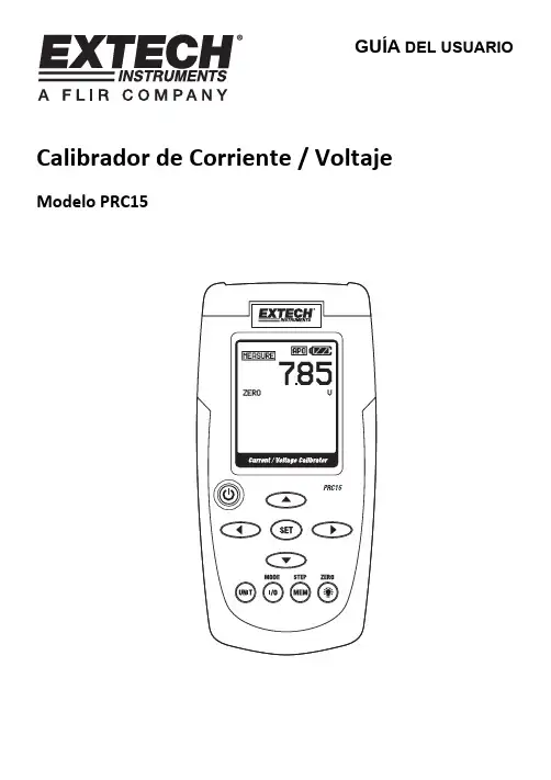
GUÍA DEL USUARIOCalibrador de Corriente / VoltajeModelo PRC15IntroducciónGracias por seleccionar el Modelo PRC15 de Extech. Este instrumento se embarca completamente probado y calibrado y con uso apropiado le proveerá muchos años de servicio confiable. Por favor visite el sitio web de Extech Instruments () para descargar la versión más reciente de esta Guía del Usuario. Extech Instruments es una compañía certificada ISO-9001. SeguridadSeñales internacionales de seguridadEsta señal adyacente a otra señal o terminal, indica que el usuario debe referirse al manualpara mayor información.Esta señal, adyacente a una terminal, indica que, bajo uso normal, pueden existir voltajespeligrososDoble aislanteNotas de seguridad∙No exceda la escala de entrada máxima permisible.∙Apague la unidad cuando el dispositivo no esté en uso.∙Quite las baterías del dispositivo si lo va a guardar más de 60 días.∙Nunca deseche las baterías en el fuego. Las baterías pueden explotar o derramar.∙Nunca mezcle tipos distintos de baterías. Siempre instale baterías nuevas del mismo tipo. Precauciones∙El uso inapropiado de este medidor puede causar daños, choque, lesiones o la muerte. Lea y comprenda este manual del usuario antes de operar este medidor.∙Quite siempre los cables de prueba antes del reemplazar la batería.∙Inspeccione la condición de los cables de prueba y el medidor mismo por daños antes de su operación. Repare o reemplace cualquier daño antes de usar.∙Si el equipo es usado en una manera no especificada por el fabricante, la protección suministrada por el equipo puede ser afectada.Descripción del medidor1. Enchufe de entrada adaptador CA2. Pantallayencendido3. Apagado4. Botones de flechas de ajuste de la fuente de salidaSET5. Botón6. Botón UNIT (mA ó %)7. Botón MODO I/O8. MEM (botón memoria STEP "paso")Retroiluminación/CERO9. Botón10. Enchufes de entrada de cables de prueba Disposición de pantalla1. Icono modo FUENTE2. Icono de estado función CERO3. Icono modo MEDICIÓN4. Icono de estado de apagado automático5. Icono de estado de la batería6. Valor modo de medición7. Icono unidades modo de medición8. Ubicación en memoria del registrador de datos9. Valor modo fuente10. Icono unidades modo FuenteTeclado Descripciones y operaciónBOTÓN DE ENCENDIDO Y FUNCIÓN DE APAGADO AUTOMÁTICO1. Use el botón POWER para encender y apagar la unidad, Cuando enciende la unidad, seejecuta una prueba autónoma corta y luego se estabilizará la pantalla.2. Cuando el símbolo de batería parpadea en la pantalla, reemplace la batería tan pronto seapráctico. La batería débil puede causar lecturas imprecisas y operación errática delmedidor.3. Este instrumento está equipado con apagado automático para apagar el medidor despuésde 10 minutos de inactividad. Para desactivar esta función; presione y sostenga el botón(POWER) de encendido hasta que se apague el icono “ATP”.Botón UNITPresione el botón UNIT en la función corriente para seleccionar las unidades mA o % o V o mV en la función voltaje. En el modo MEDICIÓN el voltaje es de escala automática.Botón I/OPresione momentáneamente el botón I/O para seleccionar ya sea la fuente (SOURCE) o medición (MEASURE) (entrada).Botón MODOEn modo MEDICIÓN, presione y sostenga el botón MODE (I/O) durante 1 segundo paraseleccionar la función corriente (mA/%) o voltaje (mV/V). Suelte el botón cuando aparezca la función deseada.BOTÓN (Retroiluminación)Presione el botón retroiluminación para encender o apagar la retroiluminación.CERO () botónEn el modo MEDICIÓN o GENERACIÓN, presione y sostenga el ZERO () botón durante 1 segundo para ajustar el medidor a cero.►◄▼ y ▲BotonesLos botones de flecha se usan para ajustar el valor de salida en modo fuente (SOURCE).1. Seleccione el modo fuente (SOURCE)2. Presione el botón ► o ◄ para seleccionar un digito para ajuste. El cursor subrayadodestella identifica el digito seleccionado.3. Presione el botón ▼ o ▲ para ajustar el valor del digito. Presione y sostenga el botón ▼ o▲ para ajustar rápidamente el valor.Botón SETEl botón SET se usa para pasar entre los 5 valores de salida guardados.1. Seleccione el modo fuente (SOURCE)2. Presione el botón SET y el valor guardado en el sitio 01 de la memoria se tomará comofuente. En la pantalla aparece "MEM.01”3. Cada vez que presione el botón SET pasa por los 5 sitios de memoria.4. Puede usar los botones de flecha para ajustar el valor en cada sitio de memoria.BOTÓN STEP/MEMEl botón "paso" STEP/MEM se usa para pasar automáticamente por los 5 valores de salidaguardados. El medidor se puede ajustar para un ciclo único de los valores guardados o para unciclo continuo.1. Seleccione el modo fuente (SOURCE)2. Presione y SOSTENGA el botón STEP/MEM. En pantalla aparecerá de manera alterna"STEPSS" (ciclo único) "STEPSC" (ciclo continuo). Suelte el botón al ver el modo deseado.3. En modo de ciclo único el medidor producirá (Fuente) la corriente o el voltaje indicado enMEM01 durante 5 segundos. Enseguida el medidor avanzará a MEM02 durante 5segundos. Esto continuará hasta MEM05 y luego regresará pos los sitios de memoria. Elciclo terminará al llegar a MEM01.4. En modo continuo el ciclo continuará hasta que sea detenido a mano.5. Presione momentáneamente el botón MEM para detener el ciclo. En pantalla aparecerábrevemente el indicador “END”.GUARDAR VALORES EN LA MEMORIALos valores predeterminados guardados en los sitios de memoria son:mA % mV V MemoriaLocalizaciónM1 4.00mA 0.0% 0mV 001V M2 8.00mA 25% 500mV 5V1001V M3 12.00mA 50% 1000mV1501V M4 16.00mA 75% 1500mVM5 20.00mA 100% 2000mV 20VPara cambiar los valores en memoria:1. Seleccione el modo fuente (SOURCE)2. Presione el botón SET para seleccionar en la memoria el sitio a cambiar.3. Presione los botones de flecha para ajustar el valor nuevo4. Presione momentáneamente el botón MEM para guardar el valor. El icono del sito enmemoria destella mientras se evalúa el valor.Modos de operaciónModo de operación (entrada) MEDIREn este modo, la unidad medirá hasta 50mADC o 20VCD.1. Encienda el medidor.2. En pantalla aparecerá "MEASURE".3. Presione y sostenga el botón MODE durante 1 segundo para seleccionar mA ó % ó mV4. Conecte el cable de calibración al medidor.5. Conecte el cable de calibración al dispositivo o circuito a prueba.6. Lea la medida en la pantalla LCD.Modo de Operación SOURCE (Fuente)En este modo la unidad puede suministrar corriente hasta 24mACD a 1000 ohmios o voltaje hasta 20.00V La corriente o voltaje se puede suministrar manualmente o en pasos desde la memoria como se explicó previamente.1. Encienda el medidor2. En pantalla aparecerá "MEASURE".3. Presione y sostenga el botón MODE durante 1 segundo para seleccionar mA ó % ó mV4. presione momentáneamente el botón “I/O” para seleccionar fuente (SOURCE).5. Presione el botón UNIT para seleccionar %/ mA o mV / V.6. Conecte el cable de calibración al medidor7. Conecte el cable de calibración al dispositivo o circuito a prueba8. Use los botones de flecha para ajustar el valor de salida deseado en el indicador inferior.El indicador superior indica el valor real de la corriente o voltaje que se suministra. Si lapantalla superior no es igual al valor establecido, ya sea las baterías necesitan serreemplazadas de la impedancia de carga está fuera del rango especificado.Soporte inclinado / ColgadorEl soporte trasero proporciona dos métodos para comodidad en la visualización.1. Tire de la parte inferior del soporte hacia fuera para colocar la unidad sobre una superficieplana para su visualización.2. Tire hacia fuera de las partes inferior y superior del soporte, y luego gire el soporte paracolgar la unidad.Reemplazo de la bateríaCuando el icono de la batería aparece en la pantalla, debe reemplazar las seis pilas AA.El compartimiento de la batería se localiza en la parte posterior del medidor.1. Abra el soporte inclinado, afloje el tornillo cabeza Philips y quite la tapa de la batería.2. Quite y reemplace las baterías, observando la polaridad.3. Reemplace y asegure la tapa de la batería.Usted, como usuario final, está legalmente obligado (Reglamento de baterías) aregresar todas las baterías usadas; ¡el desecho en el desperdicio o basura de lacasa está prohibido! Usted puede entregar sus baterías en los centros de recolecciónde su comunidad o donde sea que se venden las baterías.Desecho: Cumpla las estipulaciones legales vigentes respecto al desecho del dispositivoal final de su vida útil.Recordatorios de seguridad de baterías∙Por favor deseche las baterías responsablemente; siempre observe las normas locales, estatales y federales referentes al desecho de baterías.∙Nunca deseche las baterías en el fuego. Las baterías pueden explotar o derramar.∙Nunca mezcle diferentes tipos de baterías o nuevas y usadas. Siempre instale baterías nuevas del mismo tipo.EspecificacionesEspecificaciones generalesPantallaLCD matriz de puntos Carga Máxima1000 ohmios @ 24mA Tensión del medidor6 baterías AA o adaptador CA Apagado automático El medidor automáticamente se apaga después de 10 minutos deinactividadCapacidad de suministro de corriente 24mACD a 1000 ohmiosImpedancia voltaje de entrada 10k ohmios mínimoTemperatura de operación 5ºC a 40ºC (41ºF a 104ºF)Temperatura de almacenamiento -20o C a 60o C (-4o F a 140o F)Humedad de operación 80% máx. hasta 31°C (87°F) con disminución linear hasta 50% a40°C (104°F)Humedad de almacenamiento < 80%Altitud de operación 2000 metros (7000ft.) máximaDimensiones 159 x 80 x 44mm (6.3 x 3.2 x 1.7")Peso 234 g (8.3 oz.) no bateríasEspecificaciones de escalaModo Función Escala (resolución) Precisión (% de la lectura) Corriente 0 a 50mA (0.01mA) Porcentaje(%)-25 a 230%0.1%) 0 a 1999mV (1mV) MediciónCD Voltaje(escalaautomática)2 a 20V (0.01v) Corriente 0 a 24mA (0.01mA) Porcentaje(%)-25 a 125%0.1%) 0 a 2000mV (1mV)Suministro(fuente) CD Voltaje 0 a 20V (0.01v)± (0.01% + 1 dígito)Copyright © 2013 Extech Instruments Corporación (una empresa FLIR)Reservados todos los derechos, incluyendo el derecho de reproducción total o parcial en cualquier medio.ISO-9001 certified。
RH6015可完全替代RH6030/TTP223/QT100/TCH01 单通道触摸感应开关RH6015-C(D)规格书Revision 2.0 2015-07-16目录1. 简介 (3)2. 特点 (3)3. Die引脚示意图及坐标 (4)4. 封装引脚示意图及模式 (5)4.1 引脚示意图 (5)4.2 默认输出模式 (5)5. 订购信息 (6)6. 功能描述 (6)6.1 输出有效电平配置(AHLB) (6)6.2 快速/低功耗模式(LPMB) (6)6.3 保持/同步模式(TOG) (6)7. 应用电路图 (7)8. PCB设计注意事项 (8)9. 电气参数 (9)9.1 最大绝对额定值 (9)9.2 DC电气参数 (9)10. 封装信息(SOT23-6L) (10)1.简介RH6015 是一款内置稳压模块的单通道电容式触摸感应控制开关IC,可以替代传统的机械式开关。
RH6015可在有介质(如玻璃、亚克力、塑料、陶瓷等)隔离保护的情况下实现触摸功能,安全性高。
RH6015内置高精度稳压、上电复位、低压复位、硬件去抖、环境自适应算法等多种有效措施,大大提高自身抗干扰性能。
RH6015可通过外部引脚配置成多种工作模式,可广泛应用于灯光控制、电子玩具、消费电子、家用电器等产品中。
RH6015-C,CMOS输出。
RH6015-D,NMOS开漏输出。
2.特点•工作电压:2.3V~5.5V•最高功耗工作电流5.0 uA @3v,低功耗模式工作电流2.5uA@3v•内置高精度稳压模块•上电0.5s快速初始化•环境自适应功能,可快速应对触摸上电等类似应用场景•可靠的上电复位(POR)及低压复位(LVR)性能•芯片内置去抖动电路,有效防止由外部噪声干扰导致的误动作•通过外部引脚配置快速/低功耗模式、正常/延时模式、同步/保持模式•可通过外部引脚设置高/低电平有效输出、最大开启时间、延时时间•封装:SOT23-6L3.Die引脚示意图及坐标图 1 Die Pad 示意图(970uM x758uM 衬底接VSS)RH6015-CRH6015-D1OC TOGGNDVDDTCHAHLB62 53 41ODTOGGND VDDTCHNC62 53 44. 封装引脚示意图及模式4.1 引脚示意图图 2 RH6015-C / RH6015-D (SOT23-6L )引脚示意图表I-P L / I-P H :带内部下拉/上拉电阻的CMOS 输入 OD :CMOS 开漏输出,无保护二极管O :推挽型CMOS 输出 I/O :CMOS 输入/输出P :电源/地4.2 默认输出模式可配置:指该封装上有相应模式的配置管脚引出,具体见6.功能描述。
RH6015 是一款内置稳压模块的单通道电容式触摸感应控制开关IC,可以替代传统的机械式开关。
RH6015可通过外部引脚配置成多种工作模式,可广泛应用于灯光控制、电子玩具、消费电子、家用电器等产品中。
深圳市奥伟斯科技有限公司是一家专注触摸芯片,单片机,电源管理芯片,语音芯片,场效应管,显示驱动芯片,网络接收芯片,运算放大器,红外线接收头及其它半导体产品的研发,代理销售推广的高新技术企业。
自成立以来一直致力于新半导体产品在国内的推广与销售,年销售额超过壹亿人民币,是一家具有综合竞争优势的专业电子元器件代理商。
主要品牌产品:一、OWEIS-TECH:OWEIS 触摸芯片、 OWEIS 接口芯片、 OWEIS 电源芯片、 OWEIS 语音芯片、 OWEIS 场效应管一、电容式触摸芯片、ADSEMI 触摸芯片代理、芯邦科技触控芯片、万代科技触摸按键芯片、博晶微触摸控制芯片、海栎创触摸感应芯片、启攀微触摸、 IC 融和微触摸感应、IC 合泰触摸按键、IC 通泰触摸芯片二、汽车电子/电源管理/接口芯片/逻辑芯片:IKSEMICON 一级代理、 ILN2003ADT、IK62783DT、 IL2596、IL2576 、ILX485、 ILX3485、 ILX232 、ILX3232三、功率器件/接收头/光电开关:KODENSHI、 AUK、 SMK系列、 MOS管、SMK0260F、 SMK0460F、SMK0760F、 SMK1260F、 SMK1820F、 SMK18T50F四、LED 显示驱动芯片:中微爱芯 AIP 系列: AIP1668、 AIP1628 、AIP1629 、AIP1616 、天微电子 TM 系列: TM1628 TM1668 TM1621五、电源管理芯片:Power Integrations LNK364PN LNK564PN 芯朋微 PN8012 PN8015 AP5054 AP5056 力生美晶源微友达天钰电子FR9886 FR9888六、语音芯片:APLUS 巨华电子AP23085 AP23170 AP23341 AP23682 AP89085 AP89170 AP89341 AP89341K AP89682七、运算放大器:3PEAK 运算放大器、聚洵运算放大器、圣邦微运算放大器八八、发光二极管:OSRAM 欧司朗发光二极管、Lite-On 光宝发光二极管、Everlight 亿光发光二极管、 Kingbright 今台发光二极管九、CAN收发器:NXP恩智浦CAN收发器、Microchip微芯CAN收发器十、分销产品线:ONSEMI安森美 TI德州仪器 ADI TOSHIBA东芝 AVAGO安华高十一、 MCU单片机ABOV现代单片机MC96F系列、 Microchip微芯单片机PIC12F PIC16F PIC18F系列、 FUJITSU富仕通单片机MB95F系列、STM单片机STM32F STM32L系列、 CKS中科芯单片机CKS32F系列、TI单片机 MSP430系列、TMS320F系列、 NXP单片机LPC系列下面,奥伟斯主要给大家详细介绍融和微单键触控芯片RH6015C 的相关产品信息:RH6015C特点•工作电压:2.3V~5.5V•最高功耗工作电流5.0uA,低功耗模式工作电流2.5uA(均指VDD=3.0V且无负载)•内置高精度稳压模块•上电0.5s快速初始化•环境自适应功能,可快速应对触摸上电等类似应用场景•可靠的上电复位(POR)及低压复位(LVR)性能•芯片内置去抖动电路,有效防止由外部噪声干扰导致的误动作•通过外部引脚配置快速/低功耗模式、正常/延时模式、同步/保持模式•可通过外部引脚设置高/低电平有效输出、最大开启时间、延时时间•封装:SOT23-6L3.引脚示意图4.功能描述RH6015 可通过外部引脚配置为多种模式(表 2)。
P6015A1000X High Voltage Probe 070-8223-04SpecificationsWarranted CharacteristicsThis section lists the various warranted characteristics that describethe P6015A High V oltage Probe. Included are warranted electricaland environmental characteristics.Warranted characteristics are described in terms of quantifiableperformance limits which are warranted.The electrical characteristics listed in Table 1–3 apply under thefollowing conditions:H The probe and instrument with which it is used must have beencalibrated at an ambient temperature of between +20 °C and+30 °C.H The probe and instrument must be in an environment whoselimits are described in Table 1-3.H The probe and instrument must have had a warm-up period of atleast 20 minutes before applying elevated voltages.P6015A Instruction Manual1–23Specifications1–24P6015A Instruction ManualTable 1–3: Warranted Electrical CharacteristicsCharacteristic InformationMaximum input voltageDC + peak AC 11.5 kV to 20 kV. See frequency derating curve in Figure 1–4. (DC plus peak AC rating is limited to temperatures below 35°C.)Peak pulse40 kV a (Never exceed 20 kV rms)Duty cycle derating – 100 ms maximum duration at 10%maximum duty cycle. See duration and duty cycle derating curve in Figure 1–5.Altitude derating – Peak pulse derated linearly from 40kV at 8000feet (2440m) to 30kV at 15,000feet (4570m) altitude.Relative Humidity (RH) derating – Voltage derated with increasing temperature and relative humidity (see Figure 1–7).Bandwidth (–3 dB)Test conditions: Test oscilloscope bandwidth must be ≥100 MHz, Z source = 25 W 10-ft cable 75 MHz 25-ft cable25 MHzRise Time 210-ft cable ≤4.67 ns (calculated from bandwidth)25-ft cable≤14 ns (calculated from bandwidth)DC attenuation1000:1 ±3% (Excluding oscilloscope error)Test conditions: Oscillo-scope input resistance must be 1 M W ±2%1 Characteristic not checked in manual 2T r (ns) = .35/BW (MHz)SpecificationsP6015A Instruction Manual1–25Table 1–4: Warranted Environmental CharacteristicsCharacteristic InformationTemperatureNonoperating –55_C to +75_C (–67_F to +167_F)OperatingDC + peak AC Peak Pulse0_C to +35_C (+32_F to +95_F)0_C to +50_C (+32_F to +122_F)(See Table 1–1 on page 1–10 and Time Limitations Specification below)HumidityNonoperating / Operating 95% relative humidity at +50°C (+122°F). See Figure 1–7 for derating characteristics.Maximum altitudeNonoperating 15,000 m (50,000 ft)Operating4,600 m (15,000 ft)Peak pulse voltage derated from 40kV at 8000 feet (2440m) to 30kV at 15,000 feet (4570m).Vibration (random)Nonoperating 3.48g rms from 5 to 500Hz. Ten minutes on each axis.Operating 2.66g rms from 5 to 500Hz. Ten minutes on each axis.Shock (nonoperating)500 g, half sine, 0.5 ms duration, 18 shocks total in three axis.Time LimitationsLess than 70% of Rated Input Voltage at 0–35_C No time limit Greater than 70% of Rated Input Voltage at 0–35_C 30 minutes maximum in any 2.5 hour period 35–50_C15 minutes maximum in any 2.5 hour periodSpecifications1–26P6015A Instruction Manual0%30%70%80%95%25°C 35°C 50°C40kV 40kV40kV35kV 35kV20kV 25kV 35kVRelative HumidityFigure 1–7: Humidity Derating Chart10M1M 100k 10k 1k100M1001k10k 100k1M10M100M P r o b e I m p e d a n c e FrequencyP h a s e A n g l e0°–10°–20°–30°–40°–50°–60°–70°–80°–90°10Figure 1–8: Typical Input Impedance and PhaseSpecificationsP6015A Instruction Manual1–27Typical and Nominal CharacteristicsThis section lists the various typical and nominal characteristics that describe the P6015A High V oltage Probe.Nominal characteristics are determined by design and/or inspection.Nominal characteristics do not have tolerance limits.Typical characteristics are described in terms of typical or average performance. Typical characteristics are not warranted.Table 1–5: Typical Electrical CharacteristicsCharacteristic InformationInput resistance 100 M W ±2%. See Figure 1–8 for typical input impedance curve.Input capacitance ≤3 pF when probe is properly LF compensated. See Figure 1–8 for typical input impedance curve.LF compensation range 7 pF to 49 pFAberrations25% p-p for the first 200ns on a 100MHz oscilloscope when used with 10in (25.4cm) ground lead.<10% p-p typical after first 200ns; ±5% after the first 400ns.Temperature coefficient of DC attenuation0.006% per degree C 1Voltage coefficient of DC attenu-ation 0.018% per kV Delay time10ft cable: 14.7 ns 25ft cable: 33.3 ns1Resistor temperature rose 60_C at 20 kV rms over a 30 minute period.SpecificationsTable 1–6: Nominal Mechanical CharacteristicsCharacteristic InformationDiameter (probe body)8.9 cm (3.5 in) maximumLength (probe body)34.5 cm (13.6 in)Length (cable)10-ft cable 3.05 m (10 ft)25-ft cable7.62 m (25 ft)Compensation box 2.5 ×4.1 ×8.3 cm (1 ×1.6 ×3.25 in)Net weight (probe assembly)10-ft cable0.66 kg (1.47 lbs)25-ft cable0.75 kg (1.66 lbs)Shipping weight (includingaccessories)10-ft cable 2.85 kg (6.27 lbs)25-ft cable 2.93 kg (6.46 lbs)1–28P6015A Instruction Manual。
19-06-27 14:25D a t e o f i s s u e 2019-06-27123524_e n g .x m l2-1+7-8+9+24 V DC14+15-ConnectionAssembly•1-channel isolated barrier •24 V DC supply (Power Rail)•Current output up to 700Ω load •HART I/P and valve positioner •Line fault detection (LFD)•Accuracy 0.05 %•Terminal blocks with test sockets •Up to SIL 2 acc.to IEC 61508FunctionThis isolated barrier is used for intrinsic safety applications. It drives SMART I/P converters, electrical valves, and positioners in hazardous areas.Digital signals are superimposed on the analog values at the field or control side and are transferred bi-directionally.Current transferred across the DC/DC converter is repeated at terminals 1 and 2.An open and shorted field circuit presents a high inputimpedance to the control side to allow line fault detection by control system.If the loop resistance for the digital communication is too low, an internal resistor of 250Ω between terminals 8 and 9 is available, which may be used as the HART communication resistor.Sockets for the connection of a HART communicator are integrated into the terminals of the device.A unique collective error messaging feature is available when used with the Power Rail system.2Features19-06-27 14:25D a t e o f i s s u e 2019-06-27123524_e n g .x mlGeneral specifications Signal typeAnalog output Functional safety related parameters Safety Integrity Level (SIL) SIL 2Supply Connection Power Rail or terminals 14+, 15-Rated voltage U r20 ... 35 V DCRipplewithin the supply tolerancePower dissipation 0.8 W at 20 mA into 10 V (equivalent to 500 Ω) load Power consumption 1 W at 20 mA InputConnection side control sideConnection terminals 7-, 8+, (9+)Voltage drop approx. 4 V or internal resistance 200 Ω at 20 mAInput resistance > 100 k Ω, when wiring resistance in the field > 16 V (equivalent to 800 Ω at 20 mA)Current 4 ... 20 mA limited to approx. 25 mA OutputConnection side field side Connection terminals 1+, 2-Current 4 ... 20 mA Load 100 ... 700 ΩVoltage≥ 14 V at 20 mATransfer characteristicsAccuracy 0.05 %DeviationAfter calibrationat 20 °C (68 °F): ≤ 10 µA incl. non-linearity, calibration, hysteresis, supply and load changes Influence of ambient temperature ≤ 1 µA/KRise time< 100 µs , 10 ... 90 % step changeGalvanic isolation Input/power supply functional insulation, rated insulation voltage 50 V AC Indicators/settings Display elements LEDs Control elements DIP-switchConfiguration via DIP switchesLabelingspace for labeling at the front Directive conformity Electromagnetic compatibilityDirective 2014/30/EU EN 61326-1:2013 (industrial locations)ConformityElectromagnetic compatibility NE 21:2011Degree of protectionIEC 60529:2001Protection against electrical shock UL 61010-1:2004Ambient conditions Ambient temperature -20 ... 60 °C (-4 ... 140 °F)Mechanical specifications Degree of protectionIP20Connection screw terminals Mass approx. 150 gDimensions 20 x 124 x 115 mm (0.8 x 4.9 x 4.5 inch) , housing type B2Mountingon 35 mm DIN mounting rail acc. to EN 60715:2001Data for application in connection with hazardous areas EU-type examination certificate BAS 00 ATEX 7240Marking ¬ II (1)G [Ex ia Ga] IIC , ¬ II (1)D [Ex ia Da] IIIC , ¬ I (M1) [Ex ia Ma] I Output[Ex ia Ga] IIC, [Ex ia Da] IIIC, [Ex ia Ma] I Voltage U o 25.2 V Current I o 93 mA Power P o 585 mWSupplyMaximum safe voltage U m250 V rms (Attention! The rated voltage can be lower.)Type of protection [EEx ia]Input19-06-27 14:25D a t e o f i s s u e 2019-06-27123524_e n g .x mlGalvanic isolationInput/Output safe electrical isolation acc. to IEC/EN 60079-11, voltage peak value 375 V Output/power supply safe electrical isolation acc. to IEC/EN 60079-11, voltage peak value 375 V Directive conformityDirective 2014/34/EU EN 60079-0:2012+A11:2013 , EN 60079-11:2012 , EN 60079-15:2010International approvals UL approvalControl drawing 116-0173 (cULus)IECEx approval IECEx BAS 04.0014Approved for [Zone 0] [Ex ia] IIC, [Ex iaD], [Ex ia] IGeneral information Supplementary information Observe the certificates, declarations of conformity, instruction manuals, and manuals where applicable. For information see .Accessories Optional accessories- power feed module KFD2-EB2(.R4A.B)(.SP) - universal power rail UPR-03(-M)(-S) - profile rail K-DUCT-BU(-UPR-03)19-06-27 14:25D a t e o f i s s u e 2019-06-27123524_e n g .x mlLead monitoring, input characteristicsDuring lead breakage (>16V) in the field the input resistance is >100k Ω, the field current is <1mA and the red LED is flashing.During short circuit (<50Ω) in the field the input resistance is approx.20k Ω, the input current and the field current are approx.1mA and the red LED is flashing.The voltage drop at the current input (terminals 7-, 8+) is lower than 4V. Thus, it corresponds to an input resistance of 200Ω at 20mA. The AC input impedance corresponds to the load impedance of the unit.Adjustment SMART functionWhen using positioners, which do not meet the HART standard, set the switches to the 1 position (without SMART function) (see adjustment table).If you are using field devices with high input impedance and a control system with low output impedance, check wheather HART transparency is working correctly.If necessary, deactivate HART transparency via the DIP switches. If the impedances are combined as described above, you can for example use the device KCD2-SCD-Ex1 alternatively.Additional informationSwitch PositionFunction S1.1S1.200SMART All other switch settingsnon SMART。
RH5885H V3V100R003C10SPC122iBMC软件V308版本说明书文档版本01发布日期2018-08-13版权所有© 华为技术有限公司2018。
保留一切权利。
非经本公司书面许可,任何单位和个人不得擅自摘抄、复制本文档内容的部分或全部,并不得以任何形式传播。
商标声明和其他华为商标均为华为技术有限公司的商标。
本文档提及的其他所有商标或注册商标,由各自的所有人拥有。
注意您购买的产品、服务或特性等应受华为公司商业合同和条款的约束,本文档中描述的全部或部分产品、服务或特性可能不在您的购买或使用范围之内。
除非合同另有约定,华为公司对本文档内容不做任何明示或暗示的声明或保证。
由于产品版本升级或其他原因,本文档内容会不定期进行更新。
除非另有约定,本文档仅作为使用指导,本文档中的所有陈述、信息和建议不构成任何明示或暗示的担保。
华为技术有限公司地址:深圳市龙岗区坂田华为总部办公楼邮编:518129网址:客户服务邮箱:******************************客户服务电话:4008229999iBMC软件版本说明书目录目录目录 (ii)V308版本说明书 (1)V276版本说明书 (4)V260版本说明书 (6)V245版本说明书 (8)V242版本说明书 (9)V237版本说明书 (10)V221版本说明书 (12)V219版本说明书 (13)V218版本说明书 (14)V216版本说明书 (15)V308版本说明书发布版本日期:2018-08-13发布许可版本:V308上次更新版本:V276特性描述:●优化RTC电压告警门限。
●优化NVMe硬盘信息显示。
●新增支持SSD介质寿命监控。
●新增支持内存、QPI、PCIe的CE溢出监控和告警上报。
●FDM诊断增强,优化故障收集、故障解析以及诊断功能。
●优化RAID卡固件版本的信息描述。
●优化WEB日文界面信息显示●升级PHP版本至5.6.32,解决(CVE-2017-11143,CVE-2017-16642,CVE-2017-11145,CVE-2017-11146,CVE-2017-11142,CVE-2017-7890,CVE-2017-11144,CVE-2017-11628,CVE-2017-12933)业界已知漏洞。
CodeWarrior Development Studiofor MPC55xx/MPC56xx Microcontrollers,version 2.xx — Quick StartSYSTEM REQUIREMENTSHardware PC with 1.4 GHz Pentium®-compatible processor(1.8 GHz recommended)1GB RAM (2 GB recommended)CD-ROM drive (for installation)USB port (for communication with target hardware)Ethernet port (for network communication)2nd Ethernet port (optional, but recommended forcommunication with target hardware)Operating System Microsoft® Windows® XPWindows Vista™, 32-bit or 64-bit editionWindows 7, 32-bit or 64-bit editionDisk Space 1 GB free hard disk space (2 GB recommended),400 MB of which must be on Windows system disk This document explains how to install this CodeWarrior product and how to use the IDE to create and build an MPC55xx/MPC56xx project.1.Install the CodeWarrior software.a.Insert the CodeWarrior Development Studio installation CD in theCD drive of your PC — the CodeWarrior setup menu appears.NOTE If auto-install is disabled, run Launch.exe manually. This program is in the root directory of the installation CD.CodeWarrior Installation Menu b.Click the Launch the installer option to start the install wizard — the installation menu appears.c.Follow the wizard instructions to install the CodeWarrior software and theP&E ICDPPCNEXUS™ Starter Edition debugger. When the installation finishes, the Installation Complete page appears.d.In this page, check Yes , check for program updates .e.Click Finish — the CodeWarrior Updater window appears.2.Check for software updates.a.In the CodeWarrior Updater window, click Next — the updater checks fornewer versions of the CodeWarrior products currently on your PC.b.If updates are available, follow the on-screen instructions to downloadand install them.c.Click Finish — the updater exits and software installation is complete.1.Create a project.a.From the Windows taskbar, click start — the start menu appears.b.From this menu, select Programs > Freescale CodeWarrior >CW for MPC55xx, MPC56xx 2.xx > CodeWarrior IDE — the Startup dialog box appears.Creating and Building a ProjectStartup Dialog Boxc.From the Startup dialog box, click Create New Project — the NewProject Wizard starts and displays the microcontrollers derivative page.The list below explains the purpose of each of the other Startup dialog box options:–Load Example Project — Displays a list of "cookbook" example projects and creates a new project based on the example you select.–Load Previous Project — Displays a list of recently used projects and opens the one you select.–Start Using CodeWarrior — Lets you use the CodeWarrior IDE's main window.Microcontroller Derivative Paged.From the microcontroller derivative page, select the MPC55xx/MPC56xxmicrocontroller derivative on your target board.e.Click Next — the languages and libraries page appears.NOTE If you selected a multicore device (such as the MPC5514E or the MPC5643L), the multicore configuration page appearsinstead of the languages and libraries page. In this case, referto Targeting MPC55xx-MPC56xx Microcontrollers.pdf forinstructions. This document is in the layout here:installDir\Help\PDF.Languages and Libraries Pagef.In the Project name text box, type the name of the new project.g.In the Location text box, type the path in which to create this project.Alternatively, click Set to display a dialog box with which to selectthis path.h.Check the C checkbox.i.Uncheck the Use size optimized MSL libraries checkbox.j.Check the Use unsigned chars checkbox.k.Uncheck the Use VLE checkbox.l.Click Next — the PC-lint page appears.NOTE If OSEKTurbo is installed, the OSEK page appears. Refer to the targeting manual for instructions that explain how to fill inthis page.PC-lint Pagem.Select No.n.Click Next — the floating-point format support page appears.Floating-Point Format Support Pageo.Select Software.p.Click Finish — the wizard creates a project according to you specifications and displays it in a project window.Project Window2.Build the project.a.From the project window toolbar, click Make — the IDE compiles theproject’s source code and links the resulting object code into anELF-format executable file.Make Buttone the debugger of your choice to run and debug the executable file. NOTE This CodeWarrior product includes a source code debugger and flash programmer from P&E Micro. For instructions thatexplain how to use these tools, refer to theP&E ICDPPCNEXUS Quick Start Guide.Congratulations!You have installed your CodeWarrior software, created an MPC55xx/MPC56xx project, and built this project.NOTE If you obtained this product as part of a CodeWarriorDevelopment Suite, you now have a 30-day evaluation license.To obtain your permanent license, follow the registration andactivation instructions in the CodeWarrior Development SuiteQuick Start.If you have the Special Edition of this product, you do not haveto register because you have a permanent, but feature-limitedlicense. This license lets you develop projects that generatebinaries up to 128 KB in size. To upgrade, you must purchasethe CodeWarrior Development Suite - Professional Edition. Formore information, go to:/CodeWarriorSuites.Freescale, the Freescale logo, and CodeWarrior are trademarks of Freescale Semiconductor, Inc., Reg. U.S. Pat. & Tm. Off. The Power Architecture and word marks and the Power and logos and related marks are trademarks and service marks licensed by . All other product or service names are the property of their respective owners.© 2007-2012 Freescale Semiconductor, Inc.Information in this document is provided solely to enable system and software implementers to use Freescale Semiconductor products. There are no express or implied copyright licenses granted hereunder to design or fabricate any integrated circuits or integrated circuits based on the information in this document.Freescale Semiconductor reserves the right to make changes without further notice to any products herein. Freescale Semiconductor makes no warranty, representation or guarantee regarding the suitability of its products for any particular purpose, nor does Freescale Semiconductor assume any liability arising out of the application or use of any product or circuit, and specifically disclaims any and all liability, including without limitation consequential or incidental damages. “Typical” parameters that may be provided in Freescale Semiconductor data sheets and/or specifications can and do vary in different applications and actual performance may vary over time. All operating parameters, including “Typicals”, must be validated for each customer application by customer's technical experts. Freescale Semiconductor does not convey any license under its patent rights nor the rights of others. Freescale Semiconductor products are not designed, intended, or authorized for use as components in systems intended for surgical implant into the body, or other applications intended to support or sustain life, or for any other application in which the failure of the Freescale Semiconductor product could create a situation where personal injury or death may occur. Should Buyer purchase or use Freescale Semiconductor products for any such unintended or unauthorized application, Buyer shall indemnify and hold Freescale Semiconductor and its officers, employees, subsidiaries, affiliates, and distributors harmless against all claims, costs, damages, and expenses, and reasonable attorney fees arising out of, directly or indirectly, any claim of personal injury or death associated with such unintended or unauthorized use, even if such claim alleges that Freescale Semiconductor was negligent regarding the design or manufacture of the part.How to Contact UsCorporate Headquarters Freescale Semiconductor, Inc. 6501 William Cannon Drive West Austin, Texas 78735U.S.A.World Wide Web /codewarrior Technical Support /supportRevised: 9 February 201210Freescale, the Freescale logo and CodeWarrior are trademarks of Freescale Semiconductor, Inc., Reg. U.S. Pat. & Tm. Off.All other product or service names are the property of their respective owners. © 2010-2012 Freescale Semiconductor, Inc. 926-76773 Rev J。