PAC30A调整器说明书
- 格式:doc
- 大小:2.03 MB
- 文档页数:11
![三相晶闸管调整器PAC36P系列使用说明书[1]](https://uimg.taocdn.com/57bc134de45c3b3567ec8bde.webp)

智能交流电力控制器是中日合作超大功率固态继电器应用技术的新概念产品。
它包括三相调压/调功一体化PAC03I、工业DCS周波过零控制器ZAC10及后续系列。
额定电流40~500A,带锁相环同步电路、自动判别相位、缺相保护、上电缓启动、缓关断、散热器超温、快熔检测、电流限制、电压反馈、过流保护、串行工作状态指示、串行遥控操作器、PAC03IA还能与上位机通信,实现系统集成。
智能交流电力控制器可广泛用于工业各领域的电压调节,恒压,恒流,恒功率调节,适用于电阻性负载、电感性负载、变压器和电机软起控制等。
一. PAC03I主要技术指标:4~20mA输入: 接收阻抗120Ω调节输出分辨力:0.2°,三相触发不平衡度:不大于0.6°负载方式: PAC03I 50Hz 三相380VAC 三角形或星形中心不接地。
移相范围:0~150°50Hz 三相380VAC 星形中心接地(220V负载) 移相范围:0~175°50Hz 三相380VAC 半控整流桥。
移相范围:0~175°隔离驱动输出:8V峰值脉冲,8°~120°可变脉宽,每路可2串2并接4支同相SSR。
最大驱动电流:< 30 mA纯阻电流等级:60A、90A、120A、180A、250A、300A 散热单元:B160、B227、B301A、B361、B401配置见选型表五只LED灯状态显示:红绿黄LED三相电源指示和快熔断路指示;绿色INPUT输入信号线性指示灯。
三色状态灯: RUN绿色运行灯;ALM红色报警灯;STOP黄色闪烁的待机灯。
外部执行开关的缓起动,缓关断: 无电压接点输入闭合(ON):缓关断,时间固定3秒;开路(OFF): 由内部电位器P3设定0.2~120秒缓起动时间不接:直接运行运行过程中自动缓起动及急停: 运行过程中瞬间缺相急停,加电后自动缓起动(三缺一相方式时被取消)。


PAC30A+系列智能型SCR调功调压器说明书PAC30A+系列智能型SCR调功调压器PAC30A+系列SCR调功调压器是大功率可控硅模块应用技术的新产品。
它集三相调压/调功方式为一体,具有自动判别相位、上电缓启动、缓关断、散热器超温等功能,适用于电阻性负载和感性负载。
一.产品特点本公司自主研发生产的PAC30A+系列SCR调功调压器是集合我公司多年电加热控制经验,是专为电炉设备而设计的:其调功、调压、负载中心接地、不接地,可以由客户任意设置的一款产品,从而达到了真正的智能化。
其调压(移相导通)调功(过零导通)功能的转换只需要拨一下拨码开关即可实现,非常简单,并且,调功还具有周波功能,避免电流表指针来回摆动。
此调功/调压的功能转换,主要是多台运行时,移相导通对电网有干扰,使功率因数下降,因此,必须转换成节能环保的调功模式。
其散热风冷单元采用特殊设计的插片式散热器,比普通铝型材散热器散热效率提高了30%,更利于模块的散热,从而极大的提高了模块的使用寿命。
同时,还具有模块超温报警功能,便于及时了解模块的工作状态。
本产品结构合理,保护功能完善,规格齐全,有30A 至400A的电流容量机型可供用户选择。
该产品可广泛适用于工业热处理、电热加工、材料制造、航天航空、冶金、有色、医药、电子、食品机械、注塑机械、喷涂机械、真空镀膜机等各种设备上。
二.技术规格三. 安装及使用须知●使用前请认真阅读本说明书,严格按要求接线使用。
●本电压调整器是壁挂式,垂直安装在通风良好,不受日光直射或热辐射,无腐蚀性、无可燃性的环境中。
●负载应无短路、局部放电打火等现象,要求绝缘良好。
●特别指出:变压器负载不能空载或轻载运行。
●散热器超温保护后,如要运行,需排除故障后,再送电运行。
四. 装箱清单表PAC30A 整机一台,10K 电位器一只,说明书1 份。
降额2-3倍使用B300S-250A 350m m×244m m×265mm MTC-300A ≤164KW B350S-320A 450m m×244m m×270mm MTC-500A ≤210KW B400S-400A 463m m×304m m×300mm MTC-600A ≤260KW B400S-600A-2 463m m×304m m×300mm MTC-800A ≤395KW六.订货说明1.SCR调功调压器电流容量选择参考●一般纯阻负载:电力调整器电流容量应大于负载最大电流。

PCM30A60W MAXP .A. AMPLIFIER1. Read Instructions — All the safety and operating instructions should be read before the appliance is operated.2. Retain Instructions — The safety and operating instructions should be retained for future reference.3. Heed Warnings — All warnings on the appliance and in the operating instructions should be adhered to.4. Follow Instructions — All operating and use instructions should be followed.5. Water and Moisture — The appliance should not be used near water -for example, near a bathtub, washbowl, kitchen sink, laundry tub, swimming pool, or a wet basement.6. Ventilation — The appliance should be situated so that its location or position does not interfere with its proper ventilation. For example, the appliance should not be situated on a bed, sofa, rug, or similar surface that may block the ventilation openings: or placed in a built-in installation, such as a bookcase or cabinet that may impede the flow of air through the ventilation openings.7. Heat — The appliance should be situated away from heat sources such as radiators, heat registers, stoves, or other appliances(including amplifiers) that produce heat.8. Power Sources — The appliance should be connected to a power supply only of the type described in the operating instructions oras marked on the appliance.9. Grounding or Polarization — Precaution should be taken to insure that the grounding or polarization means of an appliance is not defeated.10. Power-Cord Protection — Power supply cords should be routed so that they are not likely to be walked on or pinched by items placed upon or against them, paying particular attention to cords at plugs, convenience receptacles, and the point at which they exit from the appliance.11. Cleaning — The appliance should be cleaned only as recommended by the manufacturer.12. Power Lines — An outside antenna system should not be located in the vicinity of overhead power lines or other electric light orpower circuits, or where it can fall into such power lines or circuits. When installing an outside antenna system, extreme care should be taken to keep from touching such power lines or circuits as contact with them might be fatal.13. Nonuse Periods — The power cord of the appliance should be unplugged from the outlet when the appliance isto be left unused for a long period of time.14. Object and Liquid Entry — Care should be taken so that objects do not fall and liquids are not spilled into the enclosure through openings.15. Carts and Stands — If the appliance is used with a cart or stand, the cart or stand should be a type recommended bythe manufacturer.An appliance and cart combination should be moved with care. Quick stops, excessive force,and uneven surfaces cause the appliance and cart combination to overturn.16. Mounting — The appliance should be mounted only as recommended by the manufacturer.17. Damage Requiring Service — The appliance should be serviced by qualified service personnel when:A. The power-supply cord or plug has been damaged.B. Objects have fallen into, or liquid has been spilled into the appliance enclosure.C. The appliance has been exposed to rain.D. The appliance has been dropped, or the enclosure damaged.E. The appliance does not appear to operate normally or exhibits a marked change in performance.18. Servicing — The user should not attempt to service the appliance beyond that described in the user’s operating instructions. All other servicing should be referred to qualified personnel.19. Overloading — Do not overload wall outlets and extension cords as this can result in a risk of fire or electric shock.20. Replacement Parts — When replacement parts are required, be sure the service technician has used replacement parts specified by the manufacturer or have the same characteristics as the original part. Unauthorized substitutions may result in fire, electric shock or other hazards.21. Safety Check — Upon completion of any service or repairs to this appliance, ask the service technician to perform safety checks to determine that the appliance is in proper operating condition.IMPORTANT SAFETY INSTRUCTIONSYour new PYLE HOME PCM Amplifiergives you the power and versatility you need in a professional sound system.The wide frequency response of it handles easily amplification of voice and music. The monitor terminal, talkover function on MIC 1, and Tel/Paging make it perfectly to use in meeting halls, auditoriums, sports events in school, and paging system in offices , anywhere you need to deliver special announcement with excellent sound.FEATURES AND CONTROLSFEATURES AND CONTROLSSPEAKER CONNECTIONOne or more speakers (4, 8 or 16 Ohms) can be connected to the amplifier with or without transformers. However, before you connect any speakers to the amplifier, the total impedance must be calculated in order to avoid damage to the amplifier. A total speaker impedance greater than 16 Ohms or less than 4 Ohms can cause this damage to occur.SYSTEM 1 : Single Speaker SystemNOTE : Connect the speaker (+) to the amplifier's 4-Ohm, 8-Ohm or 16-Ohm terminal, depending on the speaker being used.SYSTEM 2 : Two (or more) Speakers in SeriesNOTE : Connect the speaker (+) to the amplifier's 4-Ohm, 8-Ohm or 16-Ohm terminal, depending on the TOTAL IMPEDANCE of the two speakers. If each speakerhas an impedance of 8-Ohm, the total speaker impedance in this seriescofiguration is 16 ohms.SYSTEM 3 : Two (or more) Speakers in ParallelNOTE : Connect the speaker (+) to the amplifier's 4-Ohm, 8-Ohm or 16-Ohm terminal,depending on the TOTAL IMPEDANCE of the two speakers. If each speakerhas an impedance of 8-Ohm, the total speaker impedance in this seriesconfiguration is 4 ohms.SYSTEM 4 : Four Speakers in Series and ParallelNOTE : Although the description above is for connecting two series pairs of 8 Ohms speakers in a parallel hook up, you may also select to combine a series pair and a parallel pair in a parallel hook up, simply be sure you have calculated the total impedance, and attach the speaker (+) circuit wire to the proper amp terminal.SYSTEM 5 : Connecting Speakers with TransformersNOTE : When the 25V or 70V constant line voltages are used, a line matching transformer must be used with each speaker, All transformers must be connected in parallel, never connect line transformers in series.CONNECTION DIAGRAMYour Pyle Home Amplifier is anexample of superior design andSpecificationsInput Impedance AUX...................................200mV/50k-Ohm, Unbalanced MIC 1/MIC 2...........................1.0mV/600-Ohm, Balanced TEL/PAGE ............................100mV/600-Ohm, BalancedMax Output Power.........................................60 Watts x 1THD at rated output power..................1% or less at 1 kHz Frequency Response +/- 3 dB..................50 Hz to 15 kHz Signal to Noise Ratio A-Weighted MIC..........................................................................55dB AUX..........................................................................70dB TEL..........................................................................60dBSpeaker Outputs........................4-Ohm, 8-Ohm, 16-Ohm,25V, and 70V line outputs Monitor (MOH) Output.............600-Ohm 1V (head phones)and 8-Ohm 1W (speaker) Mute Level (AUX/MIC 2)............................................40dBTone Controls Treble....................................................+/- 10dB, 10 kHz Bass......................................................+/- 10dB, 100 HzPower Requirement............120V AC 60Hz/230V AC 50Hz Power Fuse.........................T 2AL 250V for 110-120V andT 1AL 250V for 220-240V Dimensions, inches (mm) WxHxD..........10.7 x 3.46 x 8.86(272 x 88 x 225) Weight, lbs (kg) ...............................................9.79 ( 4.44)Specifications are typical; individual units might vary.Specifications are subject to change and improvement without notice.。

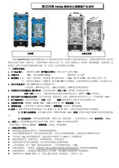
欧式风格三相电压调整器Continental style three-phasevoltage regulatorPAC30A 使用说明书OPERATINGINSTRUCTIONS希曼顿电子科技有限公司X imandun Electronic Technology Co., LtdXIMANDUN简介希曼顿电子科技有限公司,创立于1985年,是以设计开发、生产、销售全系列工业级交流固态继电器(SSR)、一体化电力调整器为主的高新技术企业,并荣获超大功率SSR、全数字化SSR控制器和柔性导热垫片等多项国家专利。
PAC30A产品概述全新PAC30A智能三相调压器以令人惊叹的完美设计开创数字式调压器的新纪元。
它操作和维护简单,独立的三只电力模块,易于散热和维护,并避免了危险集中。
欧式风格的安全防尘结构,美观大方。
红绿蓝色LED灯,工作状态一目了然。
CS插片式散热器比普通散热器的散热效率高30%~100%。
其它功能还包括:手动/自动,最大电压限制,自动判相,缺相保护,上电缓启动、缓关断、散热器超温,CS的霍尔转速检测接口,可广泛用于工业各领域中的阻性或感性负载。
订货说明1.电力调整器电流容量选择参考● 一般纯阻负载:电力调整器电流容量应大于负载最大电流。
● 硅碳棒负载:当取消变压器时,硅碳棒应串联,使之能够承受电源电压的70%~80%以上。
硅碳棒在700~800℃存在负阻区,电力调整器电流容量应大于负载最大电流的1.7倍。
● 电热管负载:电热管易受潮、局部短路和放电打火等,电力调整器电流容量应大于负载最大电流的1.7倍。
● 变压器负载:应带电流限制功能,电流容量应大于负载最大电流的2~2.5倍。
● 特殊负载应加大电流容量,订货时声明。
2.定货例:PAC30A-YT-150含义如下欧式风格三相电力调整器,负载接线方式为外三角形或中心不接地,纯组负载电流最大值为150A目录一.型号定义 (4)二.产品系列 (4)三.主要技术指标 (4)四.LED灯状态显示 (5)五.接线及应用 (5)六.初始调试 (6)七.常见故障及处理与保养维护 (7)八.尺寸图 (8)一.型号定义图1-1:负载电流150安培以下型号定义图1-2:电流150~600A 带霍尔风机型号定义注:PAC30A--40一般为自然冷却如需风冷,请订货时说明,尺寸与PAC30A--60相同四.LED灯状态显示五.接线及应用图1-3:全部功能实现接线及原理图图1-4:三相四线YN接线图各种功能接线实现组合六.初始调试为调试可靠、顺利进行,一般先接假负载(如:100~200W灯泡、电炉等)。

选型表单相调压器负载电源220VAC 恒阻负载电流80A 加热器断线报警,无特殊调功★负载电源和同步电压:调压工作方式时,负载电源和同步电压必须同相位.一. PAC01A主要技术指标:1.4~20mA输入: 接收阻抗500Ω~1.5K;调压分辨力: 0.1% 。
2.负载电源: 50Hz 单相110VAC/220VAC/380VAC 移相范围:0~170°3. 同步电源:110VAC/220VAC/380VAC,见标牌4. 外部电压调整: 10K带刻度盘电位器调整范围 0~100% 。
5.缓启、缓停: 起停开关控制缓启动、缓停时间均固定为15秒。
无起停开关控制时,第一次上电自动缓启动。
6.80℃超温保护:散热器温度大于80℃±3℃禁止输出并报警解除:故障排除后,重新上电。
7.电流容量: 40A 、 60A 、 80A 、 120A 、150A AC8. 报警输出: 光电隔离OC门输出,隔离电压1500V (5~24VDC的外供电源)。
二.三. 安装及使用须知:● 使用前请认真阅读本说明书,严格按要求接线使用。
● 本电压调整器需垂直安装在通风良好,不受日光直射或热辐射,无腐蚀性无可燃性的环境中。
● 工作电流 >30A,需采用强制风冷。
高温高湿以及海拔大于1000米,应降额使用。
● 装置过热保护后,如要再运行,需排除故障后,再送电运行。
● 工作环境温度:-10℃~+55℃ 通风良好的位置。
工作环境相对湿度: 90%。
● 负载短路保护:一般按额定负载电流的1.5倍选择,外配RS0快速熔断器作为短路保护。
● 感性负载必须使用外部起停开关和加热器断线报警HB 功能(选件) 四. 初步调试1. 初始接线:参照最简接线图接线,为调试可靠,一般先接100~200W 灯泡假负载并将仪表置手动状态。
手动电压输出范围为0~100%。
此时,负载电压应均匀变化。
仪表无手动,输入20mA ,可利用外部电压调整电位器重复试验。
PAC30A智能三相调压器,其工艺结构紧凑,外形美观(欧式风格),独立的模块,便于维护,它采用了高效插片式散热器和散热器温度测量。
功能包括:上电缓启动、缓关断、散热器超温报警、自动判相、缺相报警、外部限幅、手动、启停、手动/自动转换、继电器报警输出。
可广泛用于工业各领域中的电阻、电感性负载的调压控制。
一. 主要技术指标:1.4~20mA输入: 接收阻抗250Ω2.调节输出分辨力: 0.2 °。
线性化精度:±0.3V3.负载方式: 50Hz 三相380VAC 1)星型中心不接地/外三角型 移相范围:0~150°2)星型中心接地 ( 定货特殊申明) 移相范围:0~170°4.LED灯显示:IN绿色灯:4~20mA输入信号指示;RUN兰色运行灯:1)上电运行前闪烁三次 (表示测试状态)2)一直亮:正常运行指示3)不亮:控制器或电源故障ALM红色报警灯: 1)电源缺相: 红灯闪烁2)散热器超温:红兰灯交替闪烁。
5.缓启、缓停: 缓启、缓停时间均固定为15秒。
6.外部接点: 无电压接点。
RUN/STOP :开路 启动运行 闭合:停机 MAN/AUTO: 手动/自动,闭合时: 手动7.继电器报警输出: AL2,报警接点,容量 240VAC 1A (纯阻)8.80℃超温保护: 散热器大于80℃禁止输出并报警 解除: 故障排除后,重新上电。
9.电流容量: 每相电流 40A 、 60A 、 80A 。
10. 电源: 380VAC 1W 50HZ二. 安装及使用须知:z使用前请认真阅读本说明书,严格按要求接线使用。
z本电力调整器是壁挂式,垂直安装在通风良好,不受日光直射或热辐射,无腐蚀性无可燃性的环境中。
z工作电流 >30A,需采用强制风冷。
高温高湿以及海拔大于1000米,应降额使用。
z装置过热保护后,如要再运行,需排除故障后,再送电运行。
z在使用过程中若发生过流现象,应首先检查负载有无短路等故障。
ContentsDescription Page 1.0 Setup ................................21.1 Before Installation .....................21.2 Installation ..........................21.2.1 DIN Rail Kits ......................21.3 Wiring ..............................21.3.1 Series Wiring Applications ...........31.3.2 Parallel Wiring Applications ..........31.4 Apply Power .........................31.5 Specifications ........................41.6 Warranty . (4)Surge Protective Device XXCNXXX302Instruction Manual IM01005029E Rev. 5Effective October 2018Installation Instructions for Eaton Surge Protective Device XXCNXXX30EATON WARNINGHAZARDOUS VOLTAGES PRESENTIMPROPER INSTALLATION OR MISAPPLICATION OF THESE DEVICES MAY RESULT IN SERIOUS INJURY TO INSTALLER AND/OR DAMAGE TO ELECTRI-CAL SYSTEM OR RELATED EQUIPMENT. READ AND UNDERSTAND ALL INSTRUCTIONS BEFORE BEGINNING INSTALLATION. PROTECTIVE EYE-WEAR SHOULD BE WORN WHENEVER WORKING AROUND HAZARDOUS VOLTAGES.NOTICEALL INSTRUCTIONS AND MEASUREMENTS MUST BE COMPLETED BY A LICENSED/QUALIFIED ELECTRICIAN IN ACCORDANCE WITH THE U.S. NATIONAL ELECTRICAL CODE, STATE AND LOCAL CODES OR OTHER APPLI-CABLE COUNTRY CODES. THE U.S. NATIONAL ELECTRICAL CODE AND STATE AND LOCAL REQUIREMENTS (OR OTHER APPLICABLE COUNTRY CODES) SUPERSEDE THIS INSTRUCTION.Catalog NumberVoltage RangeMode SVR MCOV In SCCRPeak Surge CurrentXXCN0243015 - 38 Vdc 5 - 30 Vdc L-N L-G N-G N/A N/A N/A N/A 20kAXXCN04830124 - 65 Vdc 24 - 50 Vdc L-N L-G N-G N/A N/A N/AN/A65kAXXCN12030248 - 149 Vdc 1 100 -127 Vac L-N L-G N-G 5005005001501501505kA 10kA 80kAXXCN230302150 - 300 Vdc 1128 - 230 VacL-N L-G N-G8008008002752752753kA 10kA 80kA1 UL 1449 4th Edition does not list SPD products rated less than 110 Vac or DC voltages.2UL 1449 4th Edition, UL 1283 7th Edition1.0 SetupVerify that system voltages do not exceed those listed in Section 1.5, Specifications.•All AC measurements should be completed with an RMS voltme-ter.• All DC measurements should be completed with a DC voltmeter. •DO NOT INSTALL DEVICE IF MEASURED VOLTAGE EXCEEDS MAXIMUM OPERATION LIMITS.Choose location for installation so that maximum separation can be maintained between input leads, output leads and ground leads.1.1 Before InstallationREMOVE POWER FROM ELECTRICAL SYSTEM BEFORE MOUNTING DEVICE.•These devices must be mounted within an enclosure to assure personnel safety from exposed terminals.IMPORTANTDEVICE SHOULD BE LOCATED SO THAT THE SHORTEST POSSIBLE CON-DUCTOR LENGTH MAY BE USED.•Device should be mounted to allow maximum separation between input and output wiring.•Device contains no position-oriented components and can be mounted upside down or sideways.•Device should be placed in electrical circuit so that it is the last device in the circuit before equipment to be protected.1.2 InstallationDEVICE MUST BE CONNECTED TO ELECTRICAL SYSTEM WITH A CIRCUIT BREAKER:For AC Applications•1 – Single Pole / Single Throw 40A circuit breaker. The Interrupting Rating of the Circuit Breaker Shall Not Be LessThan the Available Fault Current. Circuit Breaker Ratings of 40A, 240V/415V, 10kA Min. AIC Rating.Note: Pre-existing breaker of the rated load size may be utilized if provision for multi-conductor connections are made according to N.E.C. 110-14A.•If Neutral wire is to be utilized as NEU/HOT 2 then another circuit breaker should be provided for that phase.For DC Applications•DC units to be installed after an overcurrent protective device that is rated not to exceed 100% of the current rating of the unit.REMOVE POWER FROM ELECTRICAL SYSTEM BEFORE INSTALLING DEVICE.Mechanically mount device.•Mount device using mounting flange holes or optional DIN brack-et listed below.•Device should be mounted to allow maximum separation between input and output wiring.•Device contains no position oriented components and can be mounted upside down or sideways.•Device should be placed in electrical circuit so that it is the last device in circuit before equipment to be protected.1.2.1 DIN Rail KitsMounting bracket and foot adaptable to DIN Rail systems DIN EN 50022, DIN EN 50035 and DIN EN 50045 are available through Eaton Center and can be ordered separately.• Eaton Cat# DINRAILKIT-30ACF•Eaton Innovative Technology Cat# DINRAILKIT-30ITCF1.3 WiringNOTICEAN INSULATED GROUNDING CONDUCTOR THAT IS IDENTICAL IN SIZE AND INSULATION MATERIAL AND THICKNESS TO THE GROUNDED AND UNGROUNDED CIRCUIT SUPPLY CONDUCTORS, EXCEPT THAT IT IS GREEN WITH OR WITHOUT ONE OR MORE YELLOW STRIPES, IS TO BE INSTALLED AS PART OF THE CIRCUIT THAT SUPPLIES THE DEVICE. SEE TABLE 250-122 OF THE NATIONAL ELECTRIC CODE (NEC) REGARDING THE APPROPRIATE SIZE OF THE GROUNDING CONDUCTOR.THE GROUNDING CONDUCTOR IS TO BE GROUNDED TO EARTH AT THE SERVICE EQUIPMENT OR OTHER ACCEPTABLE BUILDING EARTH GROUND SUCH AS THE BUILDING FRAME IN THE CASE OF HIGH-RISE STEEL FRAME STRUCTURE.ANY ATTACHMENT-PLUG RECEPTACLES IN THE VICINITY OF THE DEVICE ARE TO BE GROUNDING TYPE, AND THE GROUNDING CONDUCTORS SERV-ING THESE RECEPTACLES ARE TO BE CONNECTED TO EARTH GROUND AT THE SERVICE EQUIPMENT OR OTHER ACCEPTABLE BUILDING EARTH GROUND SUCH AS THE BUILDING FRAME IN THE CASE OF HIGH-RISE STEEL FRAME STRUCTURE.3Instruction Manual IM01005029E Rev. 5Effective October 2018Installation Instructions for EatonSurge Protective Device XXCNXXX30EATON NOTICEPRESSURE TERMINAL OR PRESSURE SPLICING CONNECTORS AND SOL-DERING LUGS USED IN THE INSTALLATION OF THE DEVICE SHALL BE IDENTIFIED AS BEING SUITABLE FOR THE MATERIAL OF THE CONDUC-TORS. CONDUCTORS OF DISSIMILAR METALS SHALL NOT BE INTERMIXED IN A TERMINAL OR SPLICING CONNECTOR WHERE PHYSICAL CONTACT OCCURS BETWEEN DISSIMILAR CONDUCTORS UNLESS THE DEVICE IS IDENTIFIED FOR THE PURPOSE AND CONDITIONS OF USE.CONDUCTORS SHOULD BE TWISTED TOGETHER TO REDUCE IMPEDANCE FACTOR. EXCESSIVE WIRE LENGTH AND SHARP BENDS DEGRADE FIL-TER PERFORMANCE; THEREFORE, AVOID EXCESSIVE WIRE LENGTH AND SHARP BENDS.1.3.1 Series Wiring Applications•Connect incoming system GROUND wire to terminal labeled GND on unprotected end (labeled as LINE ).•Connect load side GROUND wire to terminal labeled GND on protected end (labeled as EQUIP ).For AC Applications•Connect incoming system NEUTRAL wire to terminal labeled NEU/HOT 2 on unprotected end (labeled as LINE ).•Connect load side NEUTRAL wire to terminal labeled as NEU/HOT 2 on protected end (labeled as EQUIP ).•Connect incoming system HOT wire to terminal labeled HOT 1 on unprotected end (labeled as LINE ).•Connect load side HOT wire to terminal labeled as HOT 1 on protected end (labeled as EQUIP ).For DC Applications•Connect incoming system NEGATIVE wire to terminal labeled NEU/HOT 2 on unprotected end (labeled as LINE ).Instruction Manual IM01005029E Rev. 5Effective October 2018Installation Instructions for Eaton Surge Protective Device XXCNXXX30EatonElectrical Sector1000 Eaton Boulevard Cleveland, OH 44122United States877-ETN-CARE (877-386-2273)© 2018 EatonAll Rights Reserved Printed in USAPublication No. IM01005029E / TBG000471October 2018Eaton is a registered trademark.All other trademarks are property of their respective owners.1.5 SpecificationsDescription RatingsAgency Approvals XXCNXXX30UL1449 4th Edition, UL1283 7th Edition Type 2 SPD Terminal ConnectionsWire clamping terminals, 10-18 AWG (UL), 10-22 AWG (CSA) Torque 12 in-lbSystem voltagesDC 5 - 38 Vdc, 24 - 65 Vdc, 48 - 149 Vdc, 150 - 300 Vdc AC 100 - 127 Vac, 200 - 230 Vac Operating Temperature -40F(-40C) to +140F(+60C)Circuit Breaker 40A, 240V/415V, 10kA Min. AIC Rating (Eaton P/N:FAZ-C40/1-NA-SP)Amps*30Input Power Frequency 50/60 HzWarranty 5 Years, 10 Years if registered on /spd RoHS CompliantYes* Amp rating is for series connection only. Parallel connection is not current dependent.Figure 7. Product Dimensions1.6 WarrantyEaton warrants these products for a period of 5 years from the date of delivery to the purchaser, 10 years if registered on /spd, to be free from defects in both workmanship and materi-als. Eaton assumes no risk or liability for results of the use of the products purchased from it, including but without limiting the gen-erality of the foregoing; (1) The use in combination with any electri-cal or electronic components, circuits, systems, assemblies, or any other materials or substances; (2) Unsuitability of any product for use in any circuit or assembly.Purchaser’s right under the warranty shall consist solely of requiring Eaton to repair, or at Eaton’s sole discretion, replace, free of charge, F .O.B. factory, and defective items received at said factory or failure to give any advice or recommendations by Eaton shall not constitute any warranty by or impose any liability upon Eaton. The foregoing constitutes the sole and exclusive liability of Eaton AND IS IN LIEU OF ANY AND ALL OTHER WARRANTIES EXPRESSED, IMPLIED OR STATUTORY AS TO THE MERCHANTABILITY , FITNESS FORPURPOSE SOLD, DESCRIPTION, QUALITY , PRODUCTIVENESS OR ANY OTHER MATTER.In no event shall Eaton be liable for special or consequential dam-ages or for delay in performance of the warranty.This warranty does not apply if the product has been misused, abused, altered, tampered with, or used in applications other than specified on the nameplate. At the end of the warranty period, Eaton shall be under no further warranty obligation expressed or implied.The product covered by this warranty certificate can only be repaired or replaced by the factory. For help on troubleshooting the Critical Protection Product, or for warranty information, call 1-800-809-2772, Option 4, sub-option 2. Repair or replacement units will be returned collect. If Eaton finds the return to be a manufacturer’s defect, the product will be returned prepaid.。
Parts Manualc Fork Positioner 100F-FPS-445Model Serial Numbercascade ாcorporationPublications100FPART NO.DESCRIPTIONParts Manual208743Service Manual688261Operators Guide207363Installation Instructions680664Servicing Cascade Cylinders-VHS 679929Tool Catalog673964Literature Index Order FormSafety DecalsMounting Group SideshiftingREF QTY PART NO.DESCRIPTION 92204186Lower Hook104766154Capscrew, M16x40-8.8114667225Washer 124678990Nut 131209309Lug142208350Lower Bearing 152672018Upper Bearing163752907Capscrew, M20x50 Lg-8.8100FREF QTY PART NO.DESCRIPTION q 209451 Sideshifting Mounting - 49" s 1 1 209385 Frame - 49" s 2 1 209394 Anchor Bracket - 49" s 32601676Fitting, 6-642209542Key, M10x8x6352678528Clevis Pin 62672726Hairpin Cotter 71676649Cylinder Assembly x 81675550Washer (orifice .085)s Carriage width.q Includes items 2 through 16.x See Cylinder page for parts breakdown.Reference:BC-106SK-60422S-4096Sideshift CylinderREF QTY PART NO.DESCRIPTION676649Cylinder Assembly 11553717Nut 21662456s Seal 31553527Piston 41636852s Wiper51649817s Back-up Ring61675550Washer (orifice .085)71676776Shell 81553530Rod912789s O-Ring101615132s Back-up Ring 111553528Retainer121553688Retaining Ring 1317211Snap Ring 141662447s Seal 553866Service KitsIncluded in Service Kit 553866.Hydraulic/Fork GroupREF QTY PART NO.DESCRIPTION 132763169Capscrew, M6 x 20142680217Lockwasher158681370Capscrew, M10 x 20162209308Pin 174209306Block 182209305Grommet 192661675Clevis Pin 202672726Hairpin Cotter211763022Capscrew, M10 x 352227403Grease Fitting 231681238Lockwasher 241200008Cable Tie 255604511Fitting, 6-6●Includes items 1 through 6.❏Includes items 7 through 25.REF QTYPART NO.DESCRIPTION 388289Hydraulic Group ●388290Fork Group ❏11388331Cylinder Assembly L. H. ◆21388332Cylinder Assembly R. H. ▼31209515Hose, 18.15"41209522Hose, 45.31"51209528Hose, 15.67"61209530Hose, 31.81"72388333Fork Carrier 82209280Lug 94209303Bearing104768838Capscrew, M16 x 30114678992Lockwasher 122206923Eyebolt◆See L.H. Cylinder page for parts breakdown.▼See R.H. Cylinder page for parts breakdown.5100FReference:BC-106SK-6042120FREF QTY PART NO.DESCRIPTION388331Cylinder Assembly 11564487Shell21564494Rod31564451Retainer41564406●Rod Seal51562127●O–Ring61563388●Back–up Ring71562942Retaining Ring81562951Snap Ring91564408●Rod Wiper 101562056Piston112563278●Nylon Ring 121564141●Piston Seal 131678019Piston Nut141565183Spacer1515721Nut161564452Rod End564453Service Kit●Included in Service Kit 564453.100FREF QTY PART NO.DESCRIPTION388332Cylinder Assembly 11564501Shell21564494Rod31564451Retainer41564406●Rod Seal51562127●O–Ring61563388●Back–up Ring71562942Retaining Ring81562951Snap Ring91564408●Rod Wiper 101562056Piston112563278●Nylon Ring 121564141●Piston Seal 131678019Piston Nut141565183Spacer1515721Nut161564452Rod End564453Service Kit●Included in Service Kit 564453.Flow Divider GroupFP0035.ill100FREF QTY PART NO.DESCRIPTION209504Flow Divider Group 11209310Valve s21209311Valve Body31201527Cartridge-Combiner42663694Fitting, 352604511Fitting, 6-661601676Fitting, 6-671679992Service Kit83685105Capscrew93678993Lockwasher102207300O-Ring111604511Fitting, 6-61222680Fitting, 6-6132604510Fitting, 6141605743Fitting, 6-6s Includes items 1 through 7.Standard Installation Group100FREF QTY PART NO.DESCRIPTION209506Installation Group11207314Bracket22762899Capscrew, M10X20-8.832681238Lockwasher422453Fitting, 8-852207425HoseBackrests100FREF QTY PART NO.DESCRIPTION11209475Backrest–49"x48"in.(1245x1219 mm)s 24684586Lockwasher34200173Capscrews Width by Height.Reference:S-4098.P A R T S O R D E R I N G L O GP U R C H A S E S E R I A L R E F C A S C A D E C U S T O M E R D A T EO R D E R N U M B E RP A G E N O .Q T Y P A R T N O .P A R T N O .D E S C R I P T I O N P R I C EDo you have questions you need answered right now? Call your nearest Cascade Parts Department.Cascade (UK) Ltd.15, Orgreave Crescent Dore House Industrial Estate HandsworthSheffield S13 9NQ EnglandTel: 742-697524FAX: 742-695121Cascade Scandinavia AB Box 124Hammarvägen 10567 23 Vaggeryd SwedenTel: 42-0-393-36950 FAX: 46-0-393-36959Cascade N.V. European Headquarters P.O. Box 30091300 El Almere Damsluisweg 561332 ED AlmereThe NetherlandsTel: 31-36-5492911 FAX: 31-36-5492964Cascade Norway Østerliveien 37A 1153 Oslo NorwayTel: 47-22-743160 FAX: 47-22-743157Cascade France S.A.R.L.1D Rue De CharaintruBP 18, 91360 Epinay-Sur-OrgeMorangis Cedex, FranceTel: 33-1- 64547500FAX: 33-1-64547501Cascade Hispania S.A.Carrer 5 Sector CZona Franca DuaneraPoligono de la Zon Franca08040 Barcelona, SpainOffice No. 256Tel: 93-264-07-30FAX: 93-264-07-31Cascade Canada Inc.5570 Timberlea Blvd.Mississauga, OntarioCanada L4W-4M6Tel: 905-629-7777FAX: 905-629-7785Cascade GmbHD-41199 MonchengladbachKlosterhofweg 52GermanyTel: 49-216-668230FAX: 49-216-6682323Cascade N.V.Benelux Sales and ServiceP.O. Box 30091300 El AlmereDamsluisweg 561332 ED AlmereThe NetherlandsTel: 31-36-5492950FAX: 31-36-5492974Cascade FinlandAlbert Petreliuksenkatu 301370 VantaaFinlandTel: 358-9-836-1925FAX: 358-9-836-1935Cascade Corporation2501 Sheridan AvenueSpringfield, OH 45505Tel:888-CASCADE (227-2233)FAX: 888-329-0234Cascade Japan Ltd.5-5-41,Torikai KamiSettsu, OsakaJapan, 566Tel: 81-726-53-3490FAX: 81-726-53-3497Cascade Korea108B, Namdong Ind Complex 658-3 Gojan-Dong Namdong-GuInchon, 405-310 KoreaTel: 82-32-821-2051FAX: 82-32-821-2055Cascade Australia1445 Ipswich RoadRocklea, QLD 4106AustraliaTel: 1-800227-223FAX: (07) 3373-7333Cascade New Zealand15 Ra Ora DriveEast Tamaki, AucklandNew ZealandTel: 9-273-9136FAX: 9-273-9137Cascade (Africa) Pty. Ltd.P.O. Box 625, Isando 160060A Steel RoadSparton, Kempton ParkSouth AfricaTel: 27-11-975-9240FAX: 27-11-394-1147Cascade-XiamenNo. 668 Yangguang Rd. Xinyang Industrial Zone Haicang, Xiamen City Fujian ProvinceP.R. China 361026 Tel: 86-592-651-2500 FAX: 86-592-651-2571Cascade (Singapore) Trading Co.Four Seasons Park Autumn Block - Apt. 1802 12 Cuscaden Walk SingaporeTel: 65-834-1935FAX: 65-834-1936cᮊ Cascade Corporation 20037-2003。
调压器说明书主要用途:调压器具有波形不失真,体积小、重量轻,效率高,使用方便,运行可靠等特点,可广泛用于工业(如化工,冶金,仪器仪表,机电制造,轻工等),科学实验,公用设备,家用电器中,以实现调压,控温,调速,调光,功率控制等目的。
本系列产品分新型和老型,带J为老型,不带J为新型。
技术规格1.调压器的基本参数按表规定表1(TDGC2单相系列)2.调压器的基本参数按表规定表1(TSGC2三相系列)3.调压器额定(输出)容量:调压器额定容量按下式计算:P=√mI·u2×10^(-3)(KVA)式中:P-调压器额定输出容量(KVA)M-相数,单相M=1,三相M=3I2-额定输出电流(A)U2-最大输出电流(V)(三相为线电压)过载(%)不超过(分钟)20 6040 3060 64、调压器绝缘等级为A级,线圈平均温升限值为60℃5、过负荷能力,调压器允许短时间超过额定输出电流值。
但不能超过表2的规定基本原理与主要结构1.基本原理:调压器电刷借助于手轮主轴和刷架的作用,言线圈的磨光表面滑动,变化电刷接触位置、改变一次和二次线圈匝数比,以达到调压的目的。
2、主要结构:①单位结构:单相0.2KV A~10KV A调压器为调压单元结构,一个上端面具有一定宽度的磨光表面的线圈固定在工程塑料的底座上,接触组的电刷在弹簧压力下与线圈的磨光表面金梅接触,转动手轮带动电刷在线圈磨光表面上滑动进行调压。
单元调压器一般为台式,外面有防护通风罩。
单元调压器绕组联接如图一所示:注:图中U1-输入电压(伏)U2-输出电压(伏)D-电刷②单相组装结构,单相大容量调压器是由几个相同规格的单元组装而成,各单元的电刷接触组装在同一主轴上,线圈输入端并联连接平衡电抗器,以平衡单元间电流分布并抑制环流。
单相大容量调压器绕组联接如图2.图3所示:U1-输入电压U2-输出电压D-电刷DK DK1 DK2是平衡电抗器③三相组装结构:三相调压器由三个相同规格的单元同轴组装而成。
AC A3003DEAir CombinationFilter Regulator + LubricatorAC10A to AC60AJIS SymbolFilter Regulator LubricatorHow to Order• Option/Semi-standard: Select one each for a to l .• Option/Attachment/Semi-standard symbol: When more than one specification is required, indicate in alphanumeric order. Example) AC30A-F03DE1-KSV-136NR+++++++++Note 4)102030405060Body sizeDescriptionMetric thread (M5)Rc NPT GSymbolNilN Note 1)F Note 2)NilC DThread typeFloat type auto drainM51/81/43/81/23/41M5010203040610Port sizeaWithout auto drainFloat type auto drain (N.C.)Float type auto drain (N.O.)NilE G M E1E2E3E4Pressure gauge Digital pressure switchbWithout pressure gaugeSquare embedded type pressure gauge (with limit indicator)Round type pressure gauge (without limit indicator)Round type pressure gauge (with limit indicator)Round type pressure gauge (with color zone)Output: NPN output / Electrical entry: Wiring bottom entry Output: NPN output / Electrical entry: Wiring top entry Output: PNP output / Electrical entry: Wiring bottom entry Output: PNP output / Electrical entry: Wiring top entry NilKCheck valvec Without attachmentMounting position: AW+K +AL NilSNote 5)Pressure switchdWithout attachmentMounting position: AW+S +AL NilV3-port valve for residual pressurereleaseeWithout attachmentMounting position: AW+AL+V Nil1Note 6)Set pressuref 0.05 to 0.85 MPa setting 0.02 to 0.2 MPa setting NilJNote 9)W Note 10)Filter regulator drain port Note 8)hWith drain cock Drain guide 1/8Drain guide 1/4Drain cock with barb fitting: For ø6 x ø4 nylon tubeNil268C 6CBowl Note 7)g Polycarbonate bowl Metal bowl Nylon bowlMetal bowl with level gauge With bowl guardNylon bowl with bowl guardS e m i -s t a n d a r dA t t a c h m e n tNote 3)O p t i o n306O SBBBOSBBBBBJHJ HVMQ 2UKQ 1Q 1JGEVMUKQ 1JQ 1GR 2BCSA FR 1BCR 2R 1SFA JHDimensionsAC10A, AC20AAC30A to AC60AOUT2 x P1(Port size)C l e a r a n c e f o r m a i n t e n a n c eIN OUTP2(Pressure gauge port size)Lubricator Filter RegulatorDrainP2(Pressure gauge port size)2 x P1(Port size)C l e a r a n c e f o r m a i n t e n a n c eIN OUTLubricatorFilter RegulatorDrain OUTRound type pressure gauge AC10A to AC60ARound type pressure gauge (with color zone)AC20A to AC60AWith drain guide Drain cock with barb fittingWith drain guide Metal bowl with level gauge With auto drain (N.O./N.C.)Metal bowlWith auto drain (N.C.)Metal bowlDimensionsApplicable modelAC10A, AC20AAC20AAC30A to AC60AM5 x 0.81/8Width across flats 14N.O.: Black N.C.: Grayø10 one-touch fittingWidth across flats 171/4Barb fittingApplicable tubing: T0604Digital pressure switchSquare embedded type pressure gaugeOptionDimensionsApplicable modelAC20A to AC60ACenter of pipingCenter of pipingCenter of pipingOptional/Semi-standardspecificationsModelStandard specificationsOptional specificationsSquare type pressure gaugeDigitalpressure switchRound type pressure gaugeP1P2AB Note)CEFGJM5 x 0.81/8, 1/41/4, 3/81/4, 3/8, 1/23/43/4, 111/161/81/81/41/41/41/4 56 8311014515519119610816020123924240940948 73 86 92 93175175——303838——28 41.555 72.577.598 9835 60 8011011011011013 26 29.537.537.543.543.5K0 5 3.51.51.23.23.2H— 28 28 28 28 28 28J—27 30.538.538.544.544.5H— 27.8 27.8 27.8 27.8 27.8 27.8J—37.541 49 49 61.561.5Round type pressure gauge (with color zone)H—ø37.5ø37.5ø42.5ø42.5ø42.5ø42.5J—636676768484Hø26 ø37.5ø37.5ø42.5ø42.5ø42.5ø42.5J26636676768484AC10AAC20AAC30AAC40AAC40A-06AC50AAC60AModelOptional specificationsSemi-standard specificationsBracket mountWith auto drain With barb fitting With drain guideMetal bowlMetal bowl withlevel gaugeMQ1Q2R1R2SUV25304150507070202435404050502733—————4.55.57 9 9 11 11ø4.5 ø5.5ø7 ø9 ø9 ø11 ø1171214181820202.83.24 44.66.46.424.529 41 48 48 60 60B125177242278282448448B——209247251417417B—164208246249416416B107160214252255422422B——234272275442442AC10A AC20A AC30A AC40A AC40A-06AC50A AC60ANote) The total length of B dimension is the length when the filter regulator knob is unlocked.308Series AC10A to AC60A。
PAC-4000A发电厂自动电压调控装置技 术 说 明 书(V1.00)中国电力科学研究院CHINA ELECTRIC POWER RESEARCH INSTITUTE目录一. 装置概述 (1)二.装置主要功能 (3)2.1 电压-无功控制 (3)2.2 安全控制 (3)2.3 测量与显示 (4)2.4 统计与数据存储 (4)三.装置原理 (5)3.1 A VC控制原理 (5)3.1.1 无功或电压目标的求解 (5)3.1.2 无功功率的分解 (6)3.1.3 限制条件 (6)3.1.4 发电机功角监测和限制 (6)3.2 上位机控制流程图 (7)四.装置结构 (8)4.1 装置硬件 (8)4.2 装置软件 (8)4.3 装置屏体图 (9)4.4 控制机箱插板视图 (10)五.整定 (12)5.1 整定参数 (12)5.2 系统参数 (12)5.3 其它参数 (12)六.装置技术参数 (13)6.1 工作环境的大气条件 (13)6.2 额定参数 (13)6.2.1 直流电源 (13)6.2.3 交流电源 (13)6.2.3 交流测量回路 (13)6.2.4 直流测量回路 (13)6.3 规格参数 (13)6.3.1 子站配置 (13)6.3.2 模入信号 (14)6.3.3 模出信号 (14)6.3.4 开入信号 (14)6.3.5 开出信号 (14)6.3.6 通信接口 (14)6.3.7 显示器 (14)6.4 功率消耗 (14)6.4.1 测量回路 (14)6.4.2 电源回路 (14)七.装置技术性能指标 (15)7.1 主要功能指标 (15)7.1.1 调节精度 (15)7.2 A VR接口 (15)7.3 通讯接口 (15)7.4 交流输入 (15)7.4.1 测量范围 (15)7.4.2 测量误差 (15)7.4.3 过载能力 (16)7.5 绝缘性能 (16)7.5.1 介质强度 (16)7.5.2 绝缘电阻 (16)7.6 冲击电压 (16)7.7 耐湿热性能 (16)7.8 电磁兼容性能 (16)7.8.1 辐射电磁场抗扰度 (16)7.8.2 快速瞬变抗扰度 (16)7.8.3 脉冲群抗扰度 (16)7.8.4 静电放电抗扰度 (17)7.9 机械性能 (17)7.9.1 振动(正弦) (17)7.9.2 冲击 (17)7.9.3 碰撞 (17)一. 装置概述1.1 概述电力系统自动电压控制系统(AVC)是电网调度自动化的有机组成部分,应用先进的电子、网络通讯与自动控制技术,通过AVC对发电机无功出力进行实时跟踪调控,对变电站无功补偿设备及主变分接头进行适时调整,有效地控制区域电网无功的合理流动,优化电网内无功潮流的分布,改善电网整体的供电水平,是提高电压质量,减少网损,降低运行人员的劳动强度的重要手段。
OPERATION & MAINTENANCEINSTRUCTIONSWARNING: Read these instructions before using the machine30 TONNE HYDRAULIC PRESSMODEL NO: CSA30FPPART NO: 7615200INTRODUCTIONThank you for purchasing this CLARKE 30 Tonne Hydraulic Press.Before attempting to operate the machine, it is essential that you read this manual thoroughly and carefully follow all instructions given. In doing so you will ensure the safety of yourself and that of others around you, and you can also look forward to the press giving you long and satisfactory service.GUARANTEEThis CLARKE product is guaranteed against faulty manufacture for a period of 12 months from the date of purchase. Please keep your receipt as proof of purchase.This guarantee is invalid if the product is found to have been abused or tampered with in any way, or not used for the purpose for which it was intended.Faulty goods should be returned to their place of purchase, no product can be returned to us without prior permission.This guarantee does not effect your statutory rights.SAFETY SYMBOLSThe above safety symbols appear on the product.Hazard;-shattered workpieceHazard:- crushed handsWear Safety Shoes Wear safety glassesRead instruction manual before useSAFETY PRECAUTIONS•Due to the weight of the press, lifting equipment and the help of an assistant will be required during installation. Secure the press to a firm level floor using suitable anchor bolts (not supplied).•Before starting work, check for signs of cracked welds, loose or missing bolts, damaged screen, or any other structural damage. Do not operate if any of these conditions exist. Have repairs made only by authorised service centre.•Before work, always ensure that hydraulic hoses and couplings are completely sound.•Never tamper with the press components or modify them. The safety valve is calibrated and sealed at the factory; do not attempt to change the setting.•Use only the recommended hydraulic oil.•The components of this press are designed to withstand the rated load. Do not substitute any other components or exceed the rated load of the press.•Before applying pressure, ensure the workpiece is firmly secure and stable.•Always clean up spills of hydraulic oil immediately as this can be dangerous in a workshop environment.•Do not allow any person who is unfamiliar with hydraulic presses, to use the press unless they are under direct supervision.•Keep children and unauthorised personnel away from the work area.•Always position the safety screen directly front of the workpiece.•Always apply the load under the centre of the ram. Offset loads can damage the ram and may cause the work piece to be ejected.•Always ensure the work piece is properly supported by the press bed.•When using accessories such as pressing plates, be certain they are centered below the ram and are in full contact with the bed.•Parts being pressed may shatter or be ejected from the press. Always use adequate guards, and wear eye protection and protective clothing when using this press.•Keep hands and fingers away from parts that may pinch or shift.•Never use extension tubes to increase the length of the pump handle. Excessive effort can cause damage and/or accidents.•Wear approved impact safety goggles and heavy duty work gloves.•Failure to heed these warnings may result in damage to the equipment, or serious personal injury.UNPACKING & INVENTORYEnsure the press and its components suffered no damage during transit and that all components are present. Should any loss or damage become apparent, please contact your CLARKE dealer immediately. The following items should be present in their packages..J 1 x Pressing BedA 1 x Frame with ram / carrierassembly & hoseB 2 x Base Supports K 4 x Bed Support PinsC 4 x Stay Bars L8 x Retaining Spring ClipsD 1 x Pump with hose attached M 2 x Bed Blocks (V-blocks)E 1 x Pump Protective Cover N 1 x Protective Screen AssemblyF 1 x Pump Handle O 2 x Foot Pedal Connecting BarsG 1 x Foot Pedal 1 x Fixing Kit (bolts,nuts, washers)H 1 x Pressure GaugeASSEMBLYTOOLS REQUIRED•Wrench/socket set •PTFE tape • Hex key setASSEMBLY PROCEDUREIMPORTANT: The press must be firmly secured to a firm and level floor using expansion bolts (not supplied). Holes are provided in the feet for this purpose.IMPORTANT: Do not locate your press where it will be open to the elements, as severe weather conditions will damage the hydraulic parts.1.With the help of an assistant,attach the base supports to the frame using the nuts, bolts and washers.2.Add the stay bars to each sideand bolt into ing suitable lifting equipment ifrequired, lift the frame assembly upright and manoeuvre it to its intended location in the workshop.4.Bolt the hydraulic pump intoposition on the side of the frame using the fixing bolts and washers.WARNING: DUE TO THE WEIGHT OF THE PRESS, LIFTING EQUIPMENT OR THE HELP OF AN ASSISTANT WILL BE REQUIRED DURING INSTALLATION.frame and secure loosely with the large nut supplied Remove anyprotective bung from the gaugebefore fitting.We recommend sealing all threads with PTFE tape where hydraulic oil is to be contained. Take care not to let any oil escape while connecting the hoses.6.Screw the block connector andthe connecting piece to thepressure gauge inlet.7.Bolt the block connector to theback of the frame and connectthe pump hose to the blockconnector as shown.8.Connect the ram hose to theblock connector.9.Bolt the foot pedal to the frameusing the long bolt, spacer tube,nut and washers.10.Bolt the connecting bars to theoperating arm of the pump. Boltthem together as a pair fitting the short spacers in both positions asshown.11.Bolt the other end to the footpedal.12.Insert the bed support pins intothe holes in the frame sidesupports at a height of yourchoosing. Secure them in position using the spring clips.supplied.14.Lift the pressing bed into positionIMPORTANT: Due to the weight of the bed, we recommend that you get assistance from another person.15.Bolt the protective screenbrackets to the pressing bedplate.16.Fit the protective screen to thepositions using the latches oneach side.PREPARATION FOR USEPURGING THE HYDRAULIC SYSTEM1.Insert the pump handle into theactuating lever.2.Open the release valve by turninganti-clockwise.3.Pump several full strokes toeliminate any air bubbles from thesystem. Use either the handle orthe foot pedal.4.Close the release valve by turningclockwise.5.Top up the hydraulic oil to thelower level of the filler plug withCLARKE hydraulic oil, Part No.3050830.POSITIONING THE PRESSING BEDIMPORTANT: Due to the weight of the press bed, we recommend that you get assistance from another person when adjusting the bed height.1.Position the pressing bed so that it will be as close as possible to the ramwhen the workpiece is mounted on it.2.Raise one side of the bed and insert a bed supporting pin into the nextlocating hole.3.Repeat at the other end to level the bed.4.Repeat until the bed is at the required height, with the bed supporting pinsare secured using the spring clips.CAUTION: THE BED HEIGHT SHOULD ONLY BE RAISED OR LOWERED ONEHOLE AT A TIME, WORKING ALTERNATELY FROM ONE SIDE AND THEN THEOTHER, FAILURE TO WORK IN THIS WAY MAY CAUSE THE BED TO FALLAND CAUSE INJURY TO THE OPERATOR.POSITIONING THE RAM1.Slide the carriage along the cross-beam.2.Lock it in position with the foursprung locking bolts.IMPORTANT: Always position the ramdirectly above the workpiece.POSITIONING THE PRESSING BLOCKS The bed blocks can be placed onthe bed with either the flat face orthe V-supports facing upwards.They are prevented from slipping outof position by the retaining pins which drop down within the confines of the bed side members.Check all parts are secure andcorrectly aligned before using the press.OPERATION1.Place the workpiece on the bed. It must be completely stable andsupported by packing or shims where required. Pressing plates (bed blocks) are supplied, which locate on the bed. Place the workpiece on these to give it stability.NOTE: Any packing pieces or shims used MUST be capable ofwithstanding the pressure that will be brought to bear, and MUST be of sufficient size with sufficient surface area, so as to avoid the possibility of slipping or springing out. Mating surfaces MUST be horizontal so that the force being exerted will NOT be at an angle.2.Close the release valve by turningclockwise until tightly closed.3.Select either SLOW SPEED or FASTSPEED using the knob on the side of the pump cover.NOTE: Fast speed allows fastermovement but greater effort will be required.4.Pump the handle or foot pedal tobring the ram very lightly into contact with the workpiece.5.Manoeuvre the workpiece or loosen the bolts and slide the ram to one sideso that the desired point of contact is directly beneath the centre of the ram.6.When satisfied that the workpieceis correctly aligned and iscompletely stable in that position, raise the protective screen into position before starting any pressing.7.Slowly pump the handle or footpedal so that the ram begins to exert pressure on the workpiece.CAUTION: DO NOT POINT LOAD SUCH ACCESSORIES AS THEY ARE NOT DESIGNED TO TAKE THE FULL FORCE OF THE RAM IN ONE SPOT. ENSURE THEY ARE ADEQUATELY SUPPORTED.8.Continue to pump the handle and constantly monitor the process,ensuring the ram and work remain completely in line and there is no risk of slipping.9.Observe the reading on the pressure gauge and take care not to exceedthe rated working pressure of the press.NOTE: The scale from 30 metric tonnes upward is highlighted in red, indicating pressure being applied above the rated maximumworking pressure.10.When the pressing process is complete, turn the release valveanticlockwise in small increments to release ram pressure and allowremoval of the workpiece and lower the protective screen. TROUBLESHOOTINGProblem Probable Cause RemedyPump will not work.Dirt on valve seat/wornseals.Bleed pump unit or have unit overhauled with new seals by your Clarke dealer.Pump will not produce pressure.Pump feels hesitant under load.Pump will not lower completely.Air-lock.Open the release valveand remove the oil fillerplug. Pump the handle acouple of full strokes andclose the release valve.Replace the filler plug.Pump will not deliver pressure.Reservoir could beover-filled or have low oillevel.Check oil level byremoving the filler plugand topping up to thecorrect level.Pump feels hesitant under load.Pump cup seal could beworn out.Have the cup sealreplaced by your Clarkedealer.Pump will not lower completely.Air-lock.Release air by removingthe filler plug.MAINTENANCEROUTINELYA visual inspection must be made before each use of the press, checking for leaking hydraulic fluid and damaged, loose, or missing parts.Owners and/or users should be aware that repair of this equipment requires specialised knowledge and facilities. It is recommended that a thorough annual inspection of the press be made and that any defective parts be replaced with genuine Clarke parts.If the press appears to be damaged in any way, is found to be badly worn, or operates abnormally SHOULD BE REMOVED FROM SERVICE until the necessary repairs are made.If the press is not to be used for any length of time, store it with the ram piston withdrawn to protect the surface of the moving parts.PERIODICALLYCheck the press to make sure all bolts are tight and inspect for cracked welds, bent, loose or missing parts.Clean any foreign material from the ram carrier sliding plastic blocks. Keep the protective screen clean at all times.Check the hydraulic connections for leaks. Replace or properly repair any damaged or leaking hydraulic components before using. In the event of leaking seals, oil can be topped up via the filler plug (P34-page 17) on the end of the pump. Oil should be level with the bottom of the hole. If necessary top up with CLARKE hydraulic oil, Part No. 3050830. This task is carried out with the ram fully retracted.If any rust is apparent it must be removed completely and the paint restored.DISPOSAL OF UNWANTED MATERIALSOne of the most damaging sources of environmental pollution is oil products. Never throw away used oil with domestic refuse or flush it down a sink or drain. Collect any oil in a leak proof container and take it to your local waste disposal site.Should hydraulic components become completely unserviceable and require disposal, draw off the oil into an approved container and dispose of the product and the oil according to local regulations.TECHNICAL SPECIFICATIONSCapacity30 TonneOperating Pressure20,000 MpaRam Travel152 mmRam Shaft Diameter58 mmNet Weight167 kgDimensions D x W x H700 x 800 (exc pump) x 1850 mm Throat Width530 mmBed Adjustment Distance110 mmNo of bed positions9Throat Depth (Ram to pressing plate)Platform at highest;- 120 mmPlatform at lowest;- 557 mm Ram travel per stroke 2.7 mmNo of strokes to full extension64Pressure Gauge type Accuracy class 2.5Length of Handle600 mmGENERAL ASSEMBLY PARTS DIAGRAMFRAME ASSEMBLY PARTS LISTNOTE: When requesting spare parts, please quote the prefix JHCSA30FPfollowed by the number on the diagrams/parts lists here.NODESCRIPTION NO DESCRIPTION 1Screw 29Elbow Fitting 2Spring 30Screw 3Ball 31L ock Washer 4Heel Block 32Washer 5Screw 33Lock Washer 6Bed Frame 34Union Connector 7Circlip 35Nylon Ring 8Pin 36Union Seat 9Screw 37O-Ring 10Support 38Gauge Fitting 11Screw 39Pressure Gauge 12Frame Foot 40Connector 13Washer 41Hydraulic Hose 14Lock Washer 42Nut 15Nut 43Support 16Screw 44Bush 17Ram Securing Collar 45Spacer Tube 18Ram Mounting Plate 46Nut 19Seating Ring 47Nut 20Ram Assembly 48Foot Pedal 21Screw 49Bolt 22Slide Block 50Bolt 23R-Clip 51Bolt 24Axle 52Pump Protective Cover 25Spring 53Screw 26Adjusting Bolt 54Washer 27Hydraulic Hose 55Frame Assembly 28O-Ring 56Connecting BarNO DESCRIPTION NO DESCRIPTION R1Ram R9O-RingR2Spring R10PTFE WasherR3Screw R11Piston RodR4Nut R12WasherR5Screw R13ScrewR6O-ring R14End RingR7PTFE Washer R15Serrated Saddle R8Piston EndPUMP PARTS LISTNO DESCRIPTION NO DESCRIPTIONP1Handle Socket P19O-RingP2R-clip P20ScrewP3Clevis Pin P21Dust CapP4Connecting Rod P22BoltP5Piston P23NutP6Piston P24U-type limiterP7Nylon Ring P25WasherP8PTFE Washer P26ScrewP9Retaining Ring P27Long Release Valve P10Sealing Ring P28O-RingP11Piston Seat P29BallP12O-Ring P30Release SeatP13Washer P31WasherP14Ball P32PumpP15Ball P33Short Release Valve P16Ball Seat P34Oil FilterP17Spring P35WasherP18Screw P36ScrewDECLARATION OF CONFORMITY。
PAC30A+系列智能型SCR调功调压器说明书PAC30A+系列智能型SCR调功调压器PAC30A+系列SCR调功调压器是大功率可控硅模块应用技术的新产品。
它集三相调压/调功方式为一体,具有自动判别相位、上电缓启动、缓关断、散热器超温等功能,适用于电阻性负载和感性负载。
一.产品特点本公司自主研发生产的PAC30A+系列SCR调功调压器是集合我公司多年电加热控制经验,是专为电炉设备而设计的:其调功、调压、负载中心接地、不接地,可以由客户任意设置的一款产品,从而达到了真正的智能化。
其调压(移相导通)调功(过零导通)功能的转换只需要拨一下拨码开关即可实现,非常简单,并且,调功还具有周波功能,避免电流表指针来回摆动。
此调功/调压的功能转换,主要是多台运行时,移相导通对电网有干扰,使功率因数下降,因此,必须转换成节能环保的调功模式。
其散热风冷单元采用特殊设计的插片式散热器,比普通铝型材散热器散热效率提高了30%,更利于模块的散热,从而极大的提高了模块的使用寿命。
同时,还具有模块超温报警功能,便于及时了解模块的工作状态。
本产品结构合理,保护功能完善,规格齐全,有30A 至400A的电流容量机型可供用户选择。
该产品可广泛适用于工业热处理、电热加工、材料制造、航天航空、冶金、有色、医药、电子、食品机械、注塑机械、喷涂机械、真空镀膜机等各种设备上。
二.技术规格三. 安装及使用须知●使用前请认真阅读本说明书,严格按要求接线使用。
●本电压调整器是壁挂式,垂直安装在通风良好,不受日光直射或热辐射,无腐蚀性、无可燃性的环境中。
●负载应无短路、局部放电打火等现象,要求绝缘良好。
●特别指出:变压器负载不能空载或轻载运行。
●散热器超温保护后,如要运行,需排除故障后,再送电运行。
四. 装箱清单表PAC30A 整机一台,10K 电位器一只,说明书1 份。
降额2-3倍使用B300S-250A 350m m×244m m×265mm MTC-300A ≤164KW B350S-320A 450m m×244m m×270mm MTC-500A ≤210KW B400S-400A 463m m×304m m×300mm MTC-600A ≤260KW B400S-600A-2 463m m×304m m×300mm MTC-800A ≤395KW六.订货说明1.SCR调功调压器电流容量选择参考●一般纯阻负载:电力调整器电流容量应大于负载最大电流。
●硅碳棒负载:当取消变压器时,硅碳棒应串联,使之能够承受电源电压的70%~80%以上。
硅碳棒在700~800℃存在负阻区,电力调整器电流容量应大于负载最大电流的1.7倍。
●电热管负载:电热管易受潮、局部短路和放电打火等,SCR调功调压器电流容量应大于负载最大电流的1.7倍。
●变压器负载:应带电流限制功能,电流容量应大于负载最大电流的2~2.5倍。
●特殊负载应加大电流容量,订货时声明。
2.定货例:PAC3OA-B240S-180A,含义如下:PAC30A三相SCR调功调压器,4~20mA输入,最大电流180A(纯阻负载最大电流180A;硅碳棒负载、电热管负载最大电流110A;变压器负载最大电流80A).七.电路示意图及输出波形图电路示意图:控制板面板图:SW1拨码开关设置输出波形:八. 接假负载调试为调试可靠、顺利进行,一般先接假负载(如:100~200W灯泡、电炉等)。
负载电压变化应连续、均匀、平稳,并与输入信号成线性关系,各相电压之间应平衡。
对于变压器负载,应将变压器一次侧断开后,再接假负载。
可按最简接线图接线,进行自动或手动调试。
●自动调试: 将仪表4~20mA的输出信号接到CN1的C1、C2端,R2、R3短路,输入变化信号逐步增大时,负载电压应随输入增加。
●手动调整:外接10KΩ手动电位器。
电位器的两个固定端分别接M、R1端,滑动端接R2端。
调整手动电位器,负载电压调整范围为0~100%。
此时,负载电压应均匀变化。
●上电缓启动时间:调整控制板上的P3电位器,启动时间0.2~120秒用户可设。
九. 接实际负载调试假负载调试通过后,再接实际负载。
对于变压器负载,变压器二次侧的负载不能开路,不能空载和半载,必须加实际负载。
加电前,需保证负载没有短路、接触不良等现象,绝缘强度应满足要求,负载的连接形式应与调压器型号相符;保证调压器安装与接线应符合要求,机柜通风良好等;控制板电源电压符合要求。
加电后,逐步增加控制输入信号或调整手动电位器,使负载电压从小到大逐步增加。
若发现异常,需停机检查。
负载最大电压取决于负载特性,烘炉情况,炉温高低,负载电流大小等情况。
若变压器设计不合理,发生磁饱和时,电压也加不上去。
十.控制板常见接线组合用户可根据实际使用需要,选择接线方式。
下图列出了常见的接线组合,供设计时参考。
十三.调试中的问题及故障排除当用户系统出现故障时,首应判断故障的部位,应将仪表、调压器和负载的问题分开处理。
●负载无输出1.检查电源:控制板、负载电源是否正常,快熔是否烧断。
2.检查负载:负载是否开路或接线有问题。
3.检查控制板状态灯:绿色,运行状态;黄色闪烁,停机状态(无输出);红、绿闪烁,散热器超温报警(无输出);不亮,未供电或控制板故障。
4.检查控制板输入指示灯:红色为正常,不亮为无输入信号。
5.检查控制板P1电位器的位置:顺时针调整,输出电压增加。
6.检查控制板R2、R3短路片:自动控制时,R2、R3短路片应接好。
7.检查输入信号:范围,4~20mA。
输入信号 > 5.6mA, 应有输出。
极性是否接反。
8.检查控制板R2端:R2输出0~5V(随输入信号4~20mA变化)。
9.检查控制板RS端:RS、GND端短路,停机状态(无输出)。
●负载电压不正常1.检查电源:控制板、负载电源是否正常。
2.检查负载:是否空载、轻载运行。
变压器负载:二次侧不能空载,必须带全载。
3.手动检查:若手动控制正常,初步判断调压器没有问题。
否则,接假负载继续检查。
4.自动检查:控制输入变化4~20mA时,R2端的电压变化范围应为0~5V。
5.输出电压只能调到负载电源的一半:调压器的晶闸管模块损坏一支臂。
6.检查阻容吸收器是否接触不良或损坏。
●负载电压始终为最大且不受控输出始终为最大,无论是手动还是自动都不可调,可能原因:1.可能负载开路或未接负载2.调压器的晶闸管模块击穿损坏。
晶闸管模块输出端的电阻一般大于500KΩ。
●开始运行正常,一段时间后,输出始终为最大。
无论是手动还是自动都不可调。
关机后、再开机,又能正常运行。
可能原因:1.环境温度过高。
2.负载长期过流。
3.负载瞬时过流造成晶闸管模块热击穿。
●接假负载按最简接线调试若故障部位不易判断,可采用假负载调试法,假负载一般为100~200W的灯泡。
1.手动调节正常:初步判断调压器正常,怀疑负载有问题。
需检查负载电源电压、保险丝和接触不良、断线、短路、绝缘下降、放电打火等问题。
2.手动调节正常,自动不正常:若控制输入4~20mA电流不正常,需进一步检查仪表;否则,需检查P1电位器是否将电压限幅调得太低,R2、R3短路片是否接好。
3.手动、自动调节都正常:判断调压器没有问题。
十四.加热器特性十五. 不同负载的控制策略1.变压器控制:a)变压器的设计容量不足,造成当电流增加到一定程度时变压器铁芯饱合,导致电流剧增、波形畸变、损坏器件。
断电正在衰减的磁场)的“撞车”c) 变压器为感性负载,窄脉冲触发不可靠。
脉宽可变直流触发技术,能提供负载电流到达晶闸管擎驻电流的足够时间,确保可靠触发。
注:变压器负载不能空载调试、运行。
2.纯金属类:硅钼、钼丝、钨、白金、石墨等负载冷态电阻小,低、中温段需限压和限流;随着温度增高,电阻按线性增大,在高温段反而需增加负载电压。
PAC30A调压器的电流限制功能,是专门为这类负载设计的。
此外,带有多组PID和调节输出限幅的仪表,也可控制负载电流。
例如:日本Shimax(岛通)的MAC50、MAC3、MAC6A,MAP6等可设计低、中、高温区的调节输出限制。
3.硅碳棒: 一般采用缓启动 > 1分钟或更长和电流限制,避开在700℃附近负阻的冲击电流(新棒更明显)。
4.恒阻(泛指冷热阻变化小的负载):控制策略较简单,可采用过零调功方式,克服调压方式功率因数低、污染电网的缺点。
周期过零(占空比控制),一般采用大功率SSR实现。
周波过零调功,负载电流以全正弦波为单位均匀分布,多台设备运行时,总动力电流相对均衡(避免了周期过零方式电流集中),改善炉温均匀性,避免了电流表撞针,重要的是:提高了电源利用率和避免电力设备增容,节电效果十分明显。
PAC30A是调功调压一体化设计,既可调压也能调功(周期和周波过零两种方式),可满足不同的控制策略。
- - 10 十六.PAC30A 控制器的基本特性图示十七.调功、调压一体化功能调压方式具有负载电流冲击小、适合变压器控制等特点,但不可避免产生电源污染和降低电网功率因数。
过零调功方式避免了调压方式的不足,但无法限制电流,负载冲击电流较大。
PAC30A 的调功、调压功能提供了两者优点的结合,可根据负载情况方便地切换这两种工作方式。
内部拨码开关设置: SW1-1=ON 时,调压。
SW1-1=OFF 时,调功。
● CYC :变周期过零调功,最小分辨率为单个 周波, 也叫周波调功。
● PWM :定周期过零调功,正、负半周对称。