SMC减压阀说明书
- 格式:doc
- 大小:589.51 KB
- 文档页数:7
减压阀使用说明
(膜片阀系列)
一、准备工作
1.收到产品后,查看产品包装是否完好;打开包装,查看阀体外观、压力表是否完好。
包装损坏时请拒绝签收,并联系BVF。
2.装配阀门都有进(INLET)出(OUTLET)口标识,按标识接入管路即可。
在装阀门前,设备管路需要吹扫,接钢瓶则无需吹扫。
二、调压
1. 调压前,手柄必须在0位,即手柄逆时针旋转到头。
2. 通气,这时进口有高压,顺时针旋转手柄调压,调到需要的压力即可。
进口接钢瓶时,由于钢瓶压力随着使用会降低,这时阀门出口压力升高(手柄不动时),这是正常现象,这时可适当旋转手柄调节到需要压力即可。
手柄上有标识:INCREASE出口压力增大和DECREASE出口压力减小
3. 关闭时应先关闭阀前压力,然后关闭减压阀,手柄归0位。
这时即可泄压。
三、注意事项
1.连接阀门的管路、接头必须可靠,并满足使用压力与温度的要求,连接处要采取密封处理,不可泄漏。
2.阀门手柄不在0位时,不可通压;进口压力等于或低于设定压力(最大可调出口压力)时,不可调压,以免损坏膜片和主弹簧。
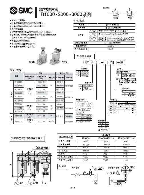
!"IR1000 2000 3000常泄口: 最大9.5l /min(ANR)在1.0MPa 压力下排气口: 最大2 l /min(ANR)在最高设定压力下最大3.5 l /min(ANR)在1.0MPa 压力下最大3.1 l /min(ANR)在1.0MPa 压力下标准型气控型应用例安装在模块式过滤组合元件上灵敏度重复精度耗气量环境及流体温度在0.2%满度以内在±0.5%满度以内-5 ~ +60℃(未冻结时)IR10□0IR20□0IR2120IR30□0IR3120最高使用压力压力表连接口径1.0MPa Rc1/8共同/规格无记号注)N 注)F NPT G Rc 注) 准标准品。
标准型气控型●体积小,重量轻。
● 比传统的精密减压阀IR200输出流量大。
● 比传统的精密减压阀IR200溢流流量大。
● 压力设定精确。
● 调节螺钉的齿间距由传统的0.75mm 改为0.5mm 。
● 安装方便,可用托架独立安装或与现在的模块式过滤组合元件AF 及AFM 直接安装。
●标准型也带面板安装。
● 先导排气口与主排气口分开。
● 可在洁净房使用(特注产品)。
!"#IR20□0-02!"IRV 000真空压力(负压)现可以任意调节!■灵敏度高■重复精度高■调节范围宽用途例工件的吸着真空测试检查装置真空泵电磁阀过滤器吸盘工件电磁阀真空泵真空罐过滤器吸盘工件真空泵电磁阀工件过滤器电磁阀压力转换器真空泵真空罐差压感应器电磁阀过滤器单一压力的情况不同压力的情况真空罐IRV IRVIRVIRV工件型号表示方法记号01020304口径1/81/43/81/2适合系列IRV1000IRV 23000IRV3000压力表接管口径接管口径大气接管口径压力表接管口径(吸盘侧)(真空泵侧)接管口径大气2-Rc1/82-Rc1/82-1/4·3/8,1/2Rc1/22-1/82-1/4。
Instruction Manual 5 Port Solenoid Valve Series VK3000The intended use of this product is to control the movement of anactuator.These safety instructions are intended to prevent hazardous situationsand/or equipment damage. These instructions indicate the level ofpotential hazard with the labels of “Caution,” “Warning” or “Danger.”They are all important notes for safety and must be followed in additionto International Standards (ISO/IEC) *1), and other safety regulations.*1) ISO 4414: Pneumatic fluid power - General rules relating to systems.ISO 4413: Hydraulic fluid power - General rules relating to systems.IEC 60204-1: Safety of machinery - Electrical equipment of machines.(Part 1: General requirements)ISO 10218-1: Robots and robotic devices - Safety requirements forindustrial robots - Part 1: Robots.•Refer to product catalogue, Operation Manual and HandlingPrecautions for SMC Products for additional information.• Keep this manual in a safe place for future reference.Warning•Always ensure compliance with relevant safety laws andstandards.•All work must be carried out in a safe manner by a qualified person incompliance with applicable national regulations.•If this equipment is used in a manner not specified by themanufacturer, the protection provided by the equipment may beimpaired.Caution•The product is provided for use in manufacturing industries only. Donot use in residential premises.2 SpecificationsNote 1) Based on dynamic performance test, JIS B 8419: 2010. (Coil temperature:20°C, at rated voltage, without surge suppressor).Note 2) Impact resistance: No malfunction occurred when it is tested with a droptester in the axial direction and at the right angles to the main valve andarmature in both energized and de-energized states every once for eachcondition. (Values quoted are for a new valve).Vibration resistance: No malfunction occurred in a one-sweep test between45 and 2000 Hz. Test was performed at both energized states in the axialdirection and at the right angles to the main valve and armature. (Valuesquoted are for a new valve).Note) At the rated voltage.2.3 Low wattage VK31#0Y type•Specifications different from standard are as follows:2.4 Light indicationFigure 1.2.5 Special productsWarningSpecial products (-X) might have specifications different from thoseshown in this section. Contact SMC for specific drawings.3 Installation3.1 InstallationWarning•Do not install the product unless the safety instructions have been readand understood.•When mounting a valve or spacer on the manifold base or sub-plate,etc., the mounting orientation is already decided. If mounted in a wrongdirection, the equipment to be connected may result in malfunction(see Figure 10 under section 3.14). VK300 series valves can bemounted on the manifold base VV5K3 of VK3000 series. Refer tocatalogue for more details.3.2 EnvironmentWarning•Do not use in an environment where corrosive gases, chemicals, saltwater or steam are present.•Do not use in an explosive atmosphere.•Do not expose to direct sunlight. Use a suitable protective cover.•Do not install in a location subject to vibration or impact in excess ofthe product’s specificati ons.•Do not mount in a location exposed to radiant heat that would result intemperatures in excess of the product’s specifications.•When the solenoid valve is mounted in a control panel or it is energizedfor a long time, make sure that the ambient temperature is within thespecification of the valve.•If using in an atmosphere where there is possible contact with waterdroplets, oil, weld spatter, etc., take suitable preventive measures.3.3 PipingCaution•Before connecting piping make sure to clean up chips, cutting oil, dustetc.•When installing piping or fittings, ensure sealant material does notenter inside the port. When using seal tape, leave 1 thread exposedon the end of the pipe/fitting.3.4 LubricationCaution•SMC products have been lubricated for life at manufacture, and do notrequire lubrication in service.•If a lubricant is used in the system, refer to catalogue for details.3.5 Air supplyWarning•Use clean air. If the compressed air supply includes chemicals,synthetic materials (including organic solvents), salinity, corrosive gasetc., it can lead to damage or malfunction.Caution•Install an air filter upstream of the valve. Select an air filter with afiltration size of 5 μm or smaller.3.6 Effect of back pressure when using a manifoldWarning•Use caution when valves are used on a manifold, because an actuatormay malfunction or unexpected movement may occur due to backpressure.•For a single acting cylinder, take appropriate measures to preventmalfunction by using it with an individual exhaust manifold.3.7 Light/surge voltage suppressorDIN Terminal (D)NoneCautionIn the case of valves without surge suppressor, the machine designershall add suppression as close as possible to the valve.Figure 5.3.8 Residual voltage of the surge voltage suppressorCaution•If a Zener diode or varistor voltage suppressor is used, the suppressorarrests the back EMF voltage from the coil to a level in proportion tothe rated voltage.•Ensure the transient voltage is within the specification of the hostcontroller.•Contact SMC for the Zener diode or varistor residual voltage.•In the case of a diode, the residual voltage is approximately 1 V.•Valve response time is dependent on surge suppression methodselected.3.9 Countermeasure for surge voltageCaution•At times of sudden interruption of the power supply, the energy storedin a large inductive device may cause non-polar type valves in a de-energized state to switch.•When installing a breaker circuit to isolate the power, consider a valvewith polarity (with polarity protection diode), or install a surgeabsorption diode across the output of the breaker.3.10 How to wire DIN terminal wiringCaution•The DIN terminal wiring connection can achieve IP65 (enclosure)rating on the connector and cable entry only when using a heavy dutycable with O.D. of Ø3.5 mm to Ø7 mm, (0.5 mm2 2 core and 3 corewires equivalent to JIS C 3306).•Cable must exit perpendicularly and not at an angle.•Tighten the ground nut and set screw within the specified torque range•IP enclosure rating for all other valve parts remain as per Table 1.•Refer to catalogue for additional details.ORIGINAL INSTRUCTIONSBody ported Base mountedVaristorCoilCoil1Varistor1(+)(+)12Diode2 (-)DiodeRed (+)Black (-) D iodeVaristorCoil1Varistor122Red (+)Black (-)Surge voltagesuppressorMarkingIndicator light(Built-inconnector)Surge voltagesuppressor(Built-in terminal)MarkingAC, 12 VDC orless for DCFor 24 V or moreLight (built-in connector)DIN type only12NeonbulbVaristor2Figure 6.Figure 7. DIN type C3.10.1 Circuit with indicator light for DIN terminalFigure 8.3.10.2 Changing cable entry directionCaution• After separating terminal block and housing, the cable entry direction can be changed by attaching the housing in the desired direction (4 directions in 90 degree increments).• In the case of valve with indicator light, avoid damaging the light with lead wire . 3.11 Extended periods of continuous energizationWarningIf a valve will be continuously energized for an extended period of time, the temperature of the valve will increase due to the heat generated by the coil assembly. This will likely adversely affect the performance of the valve and any nearby peripheral equipment. Therefore, if the valve is to be energized for periods of longer than 30 minutes at a time or if during the hours of operation the energized period per day is longer than the de-energized period, we advise using a valve with continuous duty such as SY series (with ≤0.4 W power or with power saving circuit). 3.12 Manual overrideWarningRegardless of an electric signal for the valve, the manual override is used for switching the main valve. Connected actuator is started by manual operation. Only use the manual override after confirming that there is no danger.3.13 Use as a 3-port valveCautionThe VK3000 series can be used as 3 port valve, as a N.C. or N.O. type, by plugging either 4(A) or 2(B) cylinder Port. Make sure not to plug the exhaust ports 5(R1) and 3(R2).Table 5.3.14 Mounting and removal of valvesCaution• Ensure gaskets are in good condition, not deformed and are dust and debris free.• When mounting valves ensure gaskets are present, aligned and securely in place.• Tighten the valve mounting screw and bracket screw (if required) to the appropriate tightening torque of 0.6 N·m.• Refer catalogue for details of mounting and removal of valves from manifold.Figure 9.4 How to OrderRefer to catalogue for ‘How to Order’ or product drawing for special products.5 Outline DimensionsRefer to catalogue for outline dimensions.6.1 General maintenanceCaution• Not following proper maintenance procedures could cause the product to malfunction and lead to equipment damage.• If handled improperly, compressed air can be dangerous.• Maintenance of pneumatic systems should be performed only by qualified personnel.• Before performing maintenance, turn off the power supply and be sure to cut off the supply pressure. Confirm that the air is released to atmosphere.• After installation and maintenance, apply operating pressure and power to the equipment and perform appropriate functional and leakage tests to make sure the equipment is installed correctly.• If any electrical connections are disturbed during maintenance, ensure they are reconnected correctly and safety checks are carried out as required to ensure continued compliance with applicable national regulations.• Do not make any modification to the product.• Do not disassemble the product, unless required by installation or maintenance instructions.7 Limitations of Use7.1 Limited warranty and disclaimer/compliance requirementsRefer to Handling Precautions for SMC Products. 7.2 Holding of pressure (including vacuum)WarningSince valves are subject to air leakage, they cannot be used for applications such as holding pressure (including vacuum) in a system. 7.3 Cannot be used as an emergency shut-off valveWarningThis product is not designed for safety applications such as an emergency shut-off valve. If the valves are used in this type of system, other reliable safety assurance measures should be adopted.7.4 Breathing holeCautionFigure 10.There is a breathing hole on the bottom surface of the valve. Please note that liquid may enter or block the breathing hole, which may cause malfunction.7.5 Leakage voltageCautionEnsure that any leakage voltage caused by the leakage current when the switching element is OFF causes ≤2% (for DC coils) or ≤20% (for AC coils) of rated voltage across the valve. 7.6 Low temperature operationCautionUnless otherwise indicated in the specifications for each valve, operation is possible to -10˚C, but appropriate measures should be taken to avoid solidification or freezing of drainage and moisture, etc.8 Product DisposalThis product shall not be disposed of as municipal waste. Check your local regulations and guidelines to dispose this product correctly, in order to reduce the impact on human health and the environment.9 ContactsRefer to or www.smc.eu for your local distributor/importer.URL : https:// (Global) https:// www.smc.eu (Europe) SMC Corporation, 4-14-1, Sotokanda, Chiyoda-ku, Tokyo 101-0021, JapanSpecifications are subject to change without prior notice from the manufacturer. © 2021 SMC Corporation All Rights Reserved. Template DKP50047-F-085MCompatible cable: of Ø3.5 mm to Ø7mmGround nutTightening torque WasherGrommet (Rubber) (Voltage symbol) Terminal screw (3 positions)Tightening torque 0.2 N·m to 0.25 N·mHolding screw Tightening torque 0.3 N·m to 0.4 N·m Housing (Position for light mounting) Terminal block Slot area(+)(-)1.65 N·m to2.5 N·mN·m GroundR NLLEDR RLEDD NL: Neon light R: ResistorLED: Light emitting diodeR: ResistorD: Protective diodeLED: Light emitting diode R: ResistorBleed holeP P P PRRP R RRPP P PPP P P RRP R RR RRR R RP R PRRRRRRPPPPPPR RR R。
SMC减压阀工作原理和型号介绍
一.SMC减压阀工作原理
1.顺时针调节手轮,调压弹簧被压缩,推动膜片组件下移,通过阀杆,打开阀芯,则入口气压力
经阀芯节流降压,压力输出;
2.出口压力气体经反馈管进入膜片下腔,在膜片产生一个向上的推力。
当此推力与调压弹簧力平
衡时,出口压力便稳定一定在值。
二.SMC减压阀特点
1.体积小,重量轻。
2.比传统的精密减压阀IR200输出流量大。
3. 比传统的精密减压阀IR200溢流流量大。
4.压力设定精确。
5.调节螺钉的齿间距由传统的0.75mm改为0.5mm。
6. 安装方便,可用托架独立安装或与现在的模块式过滤组合元件AF及AFM直接安装。
7.标准型也带面板安装。
8.先导排气口与主排气口分开。
9. 可在洁净房使用(特注产品)。
三.我们一起来看看ARJ1020F微型减压阀
特长:小型、轻量(16g) ;低开启压力0.02MPa;标准规格带逆流功能;集装板(可选项);
型号有:
ARJ310-01
ARJ310-01-1
ARJ310F-01-04
ARJ310F-01-06
ARJ310F-01BG041
10ARJ210M5BG241
ARJ1020F-M5-04
ARJ1020F-M5-041
ARJ1020F-M5-06
ARJ1020F-M5-061
ARJ210-M5
ARJ210-M5-1
ARJ210-M5-S
ARJ210-M5-X215
ARJM10-10 ARJM10-4。

使用说明书减压阀宏源自动化仪表有限公司概述减压阀(Reducing valve)是采用控制阀体内的启闭件的开度来调节介质的流量,将介质的压力降低,同时借助阀后压力的作用调节启闭件的开度,使阀后压力保持在一定范围内,在进口压力不断变化的情况下,保持出口压力在设定的范围内,保护其后的生活生产器具。
按结构形式可分为膜片式、弹簧薄膜式、活塞式、杠杆式和波纹管式;按阀座数目可人为单座式和双座式;按阀瓣的位置不同可分为正作用式和反作用式。
第一章 产品技术参数一、工作原理蒸汽减压阀是采用控制阀体内的启闭件的开度来调节介质的流量,将介质的压力降低,同时借助阀后压力的作用调节启闭件的开度,使阀后压力保持在一定范围内,在进口压力不断变化的情况下,保持出口压力在设定的范围内,保护其后的生活生产器具。
本类阀门在管道中一般应当水平安装。
蒸汽减压阀是气动调节阀的一个必备配件,主要作用是将气源的压力减压并稳定到一个定值,以便于调节阀能够获得稳定的气源动力用于调节控制。
蒸汽减压阀的工作由阀后压力进行控制。
当压力感应器检测到阀门压力指示升高时,减压阀阀门开度减小;当检测到减压阀后压力减小,减压阀阀门开度增大,以满足控制要求。
蒸汽减压阀—该阀门的减压比必须在一定程度上高于系统值;即使在最大或者最小流量时它也应该能够对正作用或者反作用控制信号做出响应。
这些阀门应该针对有用控制范围选择,即最大流量的20%到80%。
正常为等比型或者具有等比特性。
活塞式减压阀工作原理:减压阀出厂时,调节弹簧处于未压缩状态,此时主阀瓣和副阀瓣处于关闭状态,使用时按顺时针方向转动调节螺钉,压缩调节弹簧,使膜片下移顶开副阀瓣,介质由a孔通过副阀座到b孔进入活塞上方,活塞在介质压力作用下,向下移动推动主阀瓣离开主阀座,使介质流向阀后,同时由c孔进入膜片下方,当阀后压力超过调定压力时,推动膜片上移压缩调节弹簧。
副阀瓣随之向关闭方向移动,使流入活塞上方的介质减小,压力也随之下降,此时主阀瓣在主阀瓣弹簧力的推动下上移,使主阀瓣与主阀座的间隙减小,介质流量随之减少,使阀后压力随之下降到的新的平衡,反之当阀后压力低于调定压力时,主阀瓣和主阀座间隙增大,介质流量随之增加,使阀后压力随之增高达到新的平衡。
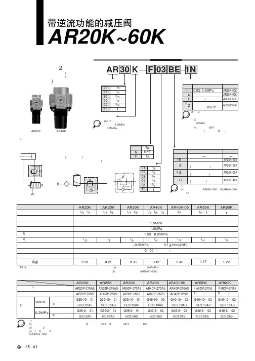
!"#$%& AR20K~60KAR25K AR30K型号表示方法阀·带逆流机构)注1)含托架及安装螺母。
注2)圆形压力表型号中的□表示连接螺纹的种类。
R为无记号、NPT为N。
连接螺纹NPT及单位表示PSI规格的压力表供给,可向营业员询问。
注3)含托架及2个安装螺钉。
注4)含1个O形圈及2个安装螺钉注5)AR50K、60K用安装螺母请向营业员咨询。
例1.气缸的杆侧和无杆侧压力不同的场合回路图AR20K81/4·3/!"#$%&AR20K~60K使用前必读。
安全上的注意、共同注意事项参见前附1~8①在确认一次侧压力表及二次侧压力表的指示压力的同时进行压力设定。
若手轮回转过分,会造成内部零部件的损坏。
②调整手轮应用手调整,不得用工具调整,以免造成损坏。
①手轮开锁后进行压力调整,调整后再锁住。
否则,手轮会损坏或二次侧压力变动。
●调整手轮外拉则开锁(调整手轮下侧看到桔黄色标记可确认)。
●将调整手轮压入则锁住,若难锁时,向左右稍稍回转一下再推压便可。
(锁住时,看不见桔黄色标记。
)②为了防止意外的手轮操作,可提供手轮套。
详见特长1。
③阀芯导座侧(手轮对侧)应留出60mm 的维修空间。
①电磁阀和执行元件等之间设置使用场合的压力表要定期检查。
一旦有剧烈的压力变化,耐久性会变短。
可考虑改用电子式压力表。
1次侧压力(P1)比设定压力高的场合,单向阀②封闭,作为通常的减压阀动作(参见图1)。
一旦1次侧压力排空,单向阀②开启,膜片室①内的压力便从1次侧排出(参见图2)。
这之后,膜片室①内的压力下降,在调压弹簧③的作用下,膜片上推,通过阀杆,将阀芯④打开,2次侧压力便顺利地从1次侧排出(参见图3)。
(1AR20K~60K流量特性(代表值)条件:一次侧压力0.7MPa31!"#$%&AR20K~60KAR20K~60K !AR20K~60K!"#$%&AR20K~60K 外形尺寸图注)仅AR20K的压力表位置在配管中心线上侧。
文件No.:AR ※-OMF0022-B○ 使用产品之前请务必阅读此使用说明书。
○ 请仔细阅读安全注意事项。
○ 为了今后方便使用,请妥善保管使用说明书。
AR25K-(F,N)02~(F,N)03(B,E,G,H)(-1,N,R,Y,Z)产品名称:带逆流功能的减压阀代表型号:AR20K-(F,N)01~(F,N)02(B,E,G,H)(-1,N,R,Y,Z)AR40K-(F,N)02~(F,N)04(B,E,G,H)(-1,N,R,Y,Z)AR40K-(F,N)06(B,E,G,H)(-1,N,R,Y,Z)使 用 说 明 书AR50K-(F,N)06~(F,N)10(B,E,G)(-1,N,R,Y,Z)AR30K-(F,N)02~(F,N)03(B,E,G,H)(-1,N,R,Y,Z)AR60K-(F,N)10(B,E,G)(-1,N,R,Y,Z)目录页1、安全注意事项 1—32、用途43、规格44、型号表示方法45、故障及对策56、构造图/零件清单67、更换操作要领 7—98、分解图 10—119、外观尺寸12SMC(中国)有限公司地址:北京市经济技术开发区兴盛街甲2号 (100176)网址:2、用途 本产品用于气路中的压力控制。
内部设有逆流功能,当入口压力与出口压力相比,下降到规定量时,出口压力将向入口侧开放。
3、型号AR20K AR25K AR30K AR40K AR40K-06AR50KAR60K 管连接口径1/8、1/41/4、3/81/4、3/81/4、3/8、1/23/43/4、11使用流体保证耐压力最高使用压力注1)设定压力范围注2)压力表连接口径环境温度及使用流体温度构造质量0.26kg 0.21kg 0.29kg 0.44kg0.47kg 1.17kg 1.22kg注1) 使1次侧压力比设定压力高0.05MPa以上。
注2) 带四方形埋入式压力计时,没有压力计连接用螺钉。
4、型号表示方法型式空气1.5MPa 1.0MPa -5~60℃(无冻结)溢流型0.05~0.85MPa1/81/4设定压力+0.05MPa{只在溢流流量为0.1L/min (ANR) 时}溢流压力5.故障与对策区分现象压力不能调整1.流向错误。
SMC阀VXD262NG说明书
1、空气在压力下从气孔溢出时所发出之声音应用。
当使用电磁阀作空气在压力下从气孔溢出时所发出之声音应用,应使用外部导向阀。
当内部导向器与外部向阀共用同一个底座时,注意空气在压力下降并影响到内部导向阀,此外,要在规范压力范围内供应压缩空气到外部阀口。
而当使用复动电磁阀作空气在压力下从气孔溢出时所发出之声音应用时,空气吹动时要确保一直供应能源。
2、低温使用。
除非每个阀有另外注明,否则操作最低温度只到负10度,但应有适当的预防措施以避免排水的凝固或冻结。
3、短暂供给能量。
若一个复动电磁阀会用在短暂供给能量,供给能量的时间至少为0.1秒,然而,以辅助的负载情况,气缸也许会故障;因此,应等到气缸回到行程端位置时再供给能量。
4、漏电。
特别使用C-R原件(保护回路)以保护切换元件,透过C-R元件产生的漏流要注意,漏电会增加。
因此,事先选择电路或元件以限制如下的残压漏电值在范围内。
另外,若因漏电而产生故障时,需要安装漏电电阻器。
请与长拓联络详细漏电电阻器。
5、安装方向。
安装方向不受限制。
3 p o r t d i r e c t a c t i n g v a l v e1063M3PA*M3PB*Note 1: Effective sectional area S and sonic conductance C are converted as S 5.0 C. 10643 p o r t d i r e c t a c t i n g v a l v e1065500 mm 1000 mm 2000 mm 3000 mmSeries variation3PA/3PB SeriesLead wire (11/0.16)1066Electric connection circuit diagram3PA/3PB Series3 p o r t d i r e c t a c t i n g v a l v e1067Pneumatic componentsSafety precautionsAlways read this section before starting use.Refer to Intro 63 for valve general precautions.3 port direct acting valve pneumatic valve 3PA/3PB SeriesThe application differs from the solenoid valve for maintaining the vacuum. When using a pad, set a filter between the pad and valve so that foreign matter does not enter.Do not use this as a solenoid valve for emergency shut down.If left pressurized for a long time, the starting response could be delayed.When using with a vacuum, select direct current (DC) specifications.Install a vacuum filter on the suction port.CAUTIONEnergizing for a long time could impair solenoid valve performance.Similar caution is required in the following use.· During intermittent energizing, it takes longer than non-energizing.· During intermittent energizing, one energizing session exceeds 30 min.Consider heat dissipating measures when installing.Consult with CKD when using this device in a continuous energizing state.During Use & MaintenanceCAUTIONThe surge suppressor enclosed with the solenoid valve is to protect the output contact for that solenoid valve's drive. There is no significant protection for the other peripheral devices, and devices could be damaged or malfunction by the surge. Surge generated by other devices could be absorbed and cause damage such as burning. Care must be taken for points below.(1) The surge suppressor functions to limit a solenoid valve surge voltage, which can reach several hundred V, to a low voltage level that the output contact can withstand. Depending on the output circuit used, this may be insufficient and could result in damage or malfunction. Check whether the surge suppressor can be used by the surge voltage limit of the solenoid valve in use, the output device's withstand pressure and circuit structure, and by the degree of return delay time.If necessary, provide other surge measures. The inverse voltage surge generated when OFF can be suppressed to the following levels.(2) When using the NPN type output unit, the voltage given in the left table and a surge voltage equivalent to the power voltage could be applied on the output transistor. Increase the contact protection circuits in this case.(3) If another device or solenoid valve is connected in parallel to the solenoid valve, the inverse voltage surge generated when the valve is OFF would apply to those devices. Even when using the solenoid valve with surge suppressor for 24 VDC, the surge voltage may reach minus several ten V depending on the model. This inverse polarity voltage could damage or cause the other devices connected in parallel to malfunction. Avoid parallel connection of devices susceptible to reversing polarity voltages, e.g., LED indicators.When driving several solenoid valves in parallel, the surge from other solenoid valves could enter the surge suppressor of one solenoid valve with a surge suppressor. Depending on the current value, that surge suppressor could burn.When driving several solenoid valves with surge suppressors in parallel, surge current could concentrate at the surge suppressor with the lowest limit voltage and cause similar burning. Even if the solenoid valve type is the same, the surge suppressor's limit voltage can be inconsistent, and in the worst case, could result in burning. Avoid driving several solenoid valves in parallel.(4) The surge suppressor incorporated in the solenoid valve often short-circuits if damaged by overvoltage or overcurrent from a source other than the solenoid valve. If the surge suppressor fails, if a large current flows when output is on, the output circuit or solenoid valve could be damaged or ignite. Do not keep power on in a faulty state.Provide an overcurrent protection circuit on the power or drive circuit or use a power supply with overcurrent protection so that alarge current does not flow continuously.(Example of output transistor protective circuit installation 1)(Example of output transistor protective circuit installation 2)Programmable controller sideSolenoid valve sideProgrammable controller sideSolenoid valve side1068D i s c r e t e 3 p o r t d i r e c t a c t i n g v a l v e10693PA/3PB SeriesDiscrete valveHow to order discrete valve10703PA SeriesDiscrete valve: Body portingInternal structure and parts list 2-position single solenoid 3PA1103PA210Repair parts listMain parts list Operational principle3P Series is a pressure balance poppet valve which is not effected by working pressure. This valve maintains large flow rale but low wattage consumption.Port can be pressurized from either 1, 2 or 3 port.The diameters of valve seat and packing seal of stem assembly are same. Since pressure differentials of each port are stabilized by through hole of stem assembly, pressure is well balanced during ON and OFF.When de-energizedThe stem assembly is pushed toward port 1 side by the plunger spring force transmitted by the plunger.Valve seat and packing seal of stem assembly close port 1, while open port 2 and 3.*Port No. 1, 2, 3 indicates; Port 1: P, NC Port 2: A, COM Port 3: R, NO23131*3: Precautions apply when assembling the coil assembly into thevalve. Contact CKD for information.D i s c r e t e 3 p o r t d i r e c t a c t i n g v a l v e10713PB SeriesDiscrete valve: Sub-plate portingInternal structure and parts list2-position single solenoid3PB1103PB210When energizedWhen energizing the coil, the plunger is absorbed toward the coil side, while the stem assembly is moved by the stem spring force. This opens port 1 and 2, but closes port 3.*Port No. 1, 2, 3 indicates; Port 1: P, NC Port 2: A, COM Port 3: R, NO23 1313PA110-M53PA1/3PA2 Series2-position single solenoid: Grommet lead wire Mounting plate: (P) 3PA210-062-position single solenoid: Grommet lead wire Mounting plate: (P)1072D i s c r e t e 3 p o r t d i r e c t a c t i n g v a l v e1073Discrete valve: Body portingDimensionsø4, ø6 push-in joint: (GS4, GS6)3PA1C-connector: (C, C1, C2, C3) D-connector: (D, D1, D2, D3) Locking manual override: (M1)3PA1/3PA2 SeriesTerminal box: (B)Terminal box: (B, L, LS)Terminal box with indicator light: (L, L2, LS)C-connector: (C, C1, C2, C3)D-connector: (D, D1, D2, D3)Locking manual override: (M1)ø4, ø6 push-in joint: (GS6, GS8)3PA2(ø6 push-in joint)10743PB110-063PB1/3PB2 Series2-position single solenoid: Grommet lead wire3PB210-06 082-position single solenoid: Grommet lead wireD i s c r e t e 3 p o r t d i r e c t a c t i n g v a l v e1075Discrete valve: Sub-plate portingDimensionsTerminal box: (B)3PB13PB2C-connector: (C, C1, C2, C3) D-connector: (D, D1, D2, D3)Locking manual override: (M1)C-connector: (C, C1, C2, C3)D-connector: (D, D1, D2, D3)Locking manual override: (M1)3PB1/3PB2 SeriesTerminal box with indicator light: (L, L2, LS)Terminal box: (B, L, LS)Note 2: Response time is the value when ON for supply pressure 0.5 MPa, pre-lubricated. The value varies depending on pressure and quality of lubricant.1076I n d i v i d u a l w i r i n g m a n i f o l d 3 p o r t d i r e c t a c t i n g v a l v e1077M3PA/M3PB SeriesIndividual wiring manifold* Gasket, set screw attachedM3PA/M3PB SeriesIndividual wiring manifoldHow to order individual wiring manifoldHow to order masking plate kit* Gasket and set screw attached5S1MP 2Indicate the quantity.How to order mixed manifold models(1) Indicate the quantity for each function (solenoid position) at the end of the model.Functions and symbols are indicated below.(2) Indicate the function (solenoid position) and layout position in the remarks field.Example: 2-position single solenoid –› S1Example: S1 = 1 to 5 (1 to 5th station is 2-position single solenoid.)2-position single solenoid (S1): 5 piece (1 to 5th station)Masking plate: 2 piece (6, 7th station)M3PB180-06-M1-B-7-3<Example of model number>For 7 stationSolenoid position symbol = , th station (facing the piping port, the left side is the 1st station.)LayoutSymbolS1 = 1 to 5 MP = 6 to 75S1MP2How to order mix manifold5S1MP2S1 = 1 to 5, MP = 6 to 71079M3PA/M3PB SeriesIndividual wiring manifoldI n d i v i d u a l w i r i n g m a n i f o l d 3 p o r t d i r e c t a c t i n g v a l v e1080M3PA180-M5M3PA1/M3PA2 SeriesPort 2 - Individual piping Port 1, 3 - Common porting: Grommet lead wireM3PA280-06Port 2 - Individual piping Port 1, 3 - Common porting: Grommet lead wire3PA119-M5-[Option]-[Voltage]Model no. of discrete solenoid valve for manifold 3PA219-06-[Option]-[Voltage]Individual wiring manifold: Body porting DimensionsM3PA1C-connector: (C, C1, C2, C3) D-connector: (D, D1, D2, D3) Locking manual override: (M1)M3PA1/M3PA2 SeriesTerminal box: (B)Terminal box with indicator light: (L, L2, LS)ø4, ø6 push-in joint: (GS4, GS6)C-connector: (C, C1, C2, C3) D-connector: (D, D1, D2, D3) Locking manual override: (M1)ø6, ø8 push-in joint: (GS6, GS8) Terminal box: (B, L, LS)M3PA2Individualwiringmanifold3portdirectactingvalve10811082M3PB180-06M3PB1 SeriesPort 2 - Individual piping Port 1, 3 - Common porting: Grommet lead wireM3PB180-06APort 2, 3 - Individual piping Port 1 - Common porting: Grommet lead wireModel no. of discrete solenoid valve for manifold 3PB119-00-[Option]-[Voltage]1083Individual wiring manifold: Sub-plate portingDimensionsM3PB1C-connector: (C, C1, C2, C3)D-connector: (D, D1, D2, D3)Locking manual override: (M1)M3PB1 SeriesTerminal box: (B)Terminal box with indicator light: (L, L2, LS)M3PB180-06BPort 1, 2 - Individual piping Port 3 - Common porting: Grommet lead wireø4, ø6 push-in joint: (GS4, GS6)I n d i v i d u a l w i r i n g m a n i f o l d 3 p o r t d i r e c t a c t i n g v a l v e1084M3PB280-06M3PB2 SeriesPort 2 - Individual piping Port 1, 3 - Common porting: Grommet lead wireM3PB280-06YPort 2 - Back porting Port 1, 3 - Common portingM3PB280-06APort 2, 3 - Individual piping Port 1 - Common porting: Grommet lead wireModel no. of discrete solenoid valve for manifold 3PB219-00-[Option]-[Voltage]Model no. of discrete solenoid valve for manifold 3PB219-00-[Option]-[Voltage]JIS symbolJIS symbol1085Individual wiring manifold: Sub-plate portingDimensionsM3PB2C-connector: (C, C1, C2, C3)D-connector: (D, D1, D2, D3)Locking manual override: (M1)M3PB2 SeriesTerminal box: (B, L, LS)M3PB280-06BPort 1, 2 - Individual piping Port 3 - Common porting: Grommet lead wireø6, ø8 push-in joint: (GS6, GS8)I n d i v i d u a l w i r i n g m a n i f o l d 3 p o r t d i r e c t a c t i n g v a l v e10862°3PA/3PB SeriesTechnical data (1) How to wire terminal box wiring and connectorHow to wire terminal box wiring and connectorRefer to the following drawing, and wire the terminal boxfollowing steps 1) to 3) below.1) Pass the cap (4), washer (5), and gasket (6) in order through the cabtire cable (7), and insert in case (2).2) When using a crimp terminal, treat the cabtire cable (7) at an appropriate length as shown in the figure, and crimp the crimp terminal (8) onto the end.3) Remove screw (10) from terminal gland (3), and pass through crimp terminal (8). (When using the Y type terminal, loosen and sandwich the terminal.) Then, tighten screw (10) again. Note: Tighten at torque of 0.5 N·m ±15%.Remarks: Bare wires can be wired. In this case, loosen screw (10), andinsert leads into the fitting, then tighten again.The cord’s direction can be changed by pulling the gland out of the case, rotating it 180°, then pressing it into the case again.The following crimp terminals (8) can be used.Use equivalent products when using other brands.3 p o r t d i r e c t a c t i n g v a l v e1087O.D. ø4 to 6.5Tighten the lead wire with the set screw.A small flat-tipped screwdriver is required.23( )Note: Do not tighten together with thesurge suppressor.Insert the gasket andterminal block into the voltage terminal and grounding terminal.Technical data (1) How to wire terminal box wiring and connector3PA/3PB SeriesPower consumption 1.8 W becomes 2.0 W when the 24 VDC light is enclosed.。
Instruction ManualElectric Actuator / Rod Type Series LEYGMotor: AC servo motor (100-200 VAC)The intended use of thisElectrical Actuator is to convert an electrical input signal into mechanical motion.1 Safety InstructionsThese safety instructions are intended to prevent hazardous situations and/or equipment damage. These instructions indicate the level of potential hazard with the labels of “Caution,” “Warning” or “Danger.” They are all important notes for safety and must be followed in addition to International Standards (ISO/IEC) *1), and other safety regulations. *1)ISO 4414: Pneumatic fluid power - General rules relating to systems. ISO 4413: Hydraulic fluid power - General rules relating to systems.IEC 60204-1: Safety of machinery - Electrical equipment of machines. (Part 1: General requirements)ISO 10218-1: Manipulating industrial robots -Safety. etc.∙ Refer to the product catalogue, Operation Manual and Handling Precautions for SMC Products for additional information. ∙ Keep this manual in a safe place for future reference.CautionCaution indicates a hazard with a low level of risk which, ifnot avoided, could result in minor or moderate injury.WarningWarning indicates a hazard with a medium level of riskwhich, if not avoided, could result in death or serious injury.DangerDanger indicates a hazard with a high level of risk which, ifnot avoided, will result in death or serious injury.Warning∙ Always ensure compliance with relevant safety laws and standards.All work must be carried out in a safe manner by a qualified person in compliance with applicable national regulations.2 SpecificationsSeries LEYG - Motor: Step [servo 24 VDC]Product Weight [kg]30501001502002503003050100150200250300Incremental E ncoder[S2] 1.80 1.99 2.31 2.73 3.07 3.41 3.67 1.81 2.02 2.26 2.69 2.95 3.27 3.51AbsoluteE ncoder[S6] 1.86 2.05 2.37 2.79 3.13 3.47 3.73 1.87 2.08 2.32 2.75 3.01 3.33 3.57AbsoluteE ncoder[T6] 1.80 2.00 2.40 2.80 3.10 3.50 3.70 1.90 2.10 2.30 2.70 3.00 3.30 3.60Absolute E ncoder[V6]1.701.902.202.603.003.303.601.701.902.202.602.903.203.4030501001502002503003050100150200250300Incremental E ncoder[S2] 3.24 3.50 4.05 4.80 5.35 5.83 6.28 3.24 3.51 3.90 4.64 5.06 5.56 5.96AbsoluteE ncoder[S6] 3.18 3.44 3.99 4.74 5.29 5.77 6.22 3.18 3.45 3.84 4.58 5.00 5.50 5.90AbsoluteE ncoder[T6] 3.20 3.40 4.00 4.70 5.30 5.70 6.20 3.20 3.40 3.80 4.60 5.00 5.50 5.90Absolute E ncoder[V6]3.103.404.004.705.305.706.203.103.403.804.505.005.505.90In-line Motor Type30501001502002503003050100150200250300IncrementalE ncoder[S2] 1.83 2.02 2.34 2.76 3.10 3.44 3.70 1.84 2.05 2.29 2.72 2.98 3.30 3.54AbsoluteE ncoder[S6] 1.89 2.08 2.40 2.82 3.16 3.50 3.76 1.90 2.11 2.35 2.78 3.04 3.36 3.60AbsoluteE ncoder[T6] 1.90 2.10 2.40 2.80 3.10 3.50 3.70 1.90 2.10 2.30 2.80 3.00 3.30 3.60Absolute E ncoder[V6]1.701.902.202.603.003.303.601.702.002.202.602.903.203.4030501001502002503003050100150200250300Incremental E ncoder[S2] 3.26 3.52 4.07 4.82 5.37 5.85 6.30 3.26 3.53 3.92 4.66 5.08 5.58 5.98AbsoluteE ncoder[S6] 3.20 3.46 4.01 4.76 5.31 5.79 6.24 3.20 3.47 3.86 4.60 5.02 5.52 5.92AbsoluteE ncoder[T6] 3.20 3.40 4.00 4.70 5.30 5.80 6.20 3.20 3.40 3.80 4.60 5.00 5.50 5.90Absolute E ncoder[V6]3.203.404.004.705.305.806.203.203.403.804.605.005.505.90Stroke[mm] TypeofMotorLEYG32M LEYG32L Stroke[mm] TypeofMotorSeriesSeriesLEYG25M LEYG25L LEYG25M LEYG25L Stroke[mm] SeriesLEYG32M LEYG32L Stroke[mm] TypeofMotorTypeofMotorSeries2 Specifications (continued)A dditional Weight2532Incremental E ncoder[S2]0.200.40Absolute E ncoder[S6]0.300.66Absolute E ncoder[T6]0.300.70Absolute E ncoder[V6]0.300.60Size LockNote 1) Please consult with SMC for non-standard strokes produced tospecial order.Note 2) This is the maximum value of the horizontal work load. Anexternal guide is necessary to support the load. The actual work load changes according to the condition of the external guide. Confirm the load using the actual device.Note 3) Thrust setting range when "pushing" operation in torque controlmode, etc. Refer to the thrust conversion graph shown in the catalogue as a guide.Set value LEYG25#S/32#S: 15 to 30% Set value LEYG25#T/32#T: 12 to 24% Set value LEYG25#V/32#V: 45 to 90%Note 4) The allowable speed changes according to the stroke.Note 5) The allowable collision speed for collision with the workpiecewith the torque control mode.Note 6) A reference value for correcting an error in reciprocal operation. Note 7) Impact resistance: No malfunction occurred when the actuatorwas tested with a drop tester in both an axial direction and perpendicular direction to the lead screw (the test was performed with the actuator in the initial state).Vibration resistance:No malfunction occurred in a test ranging between 45 to 2000 Hz, when the actuator was tested in both an axial direction and a perpendicular direction to the lead screw (the test was performed with the actuator in the initial state).Note 8) When the motor type is "T6-T9",the resolution will changedepending on the driver type.Note 9) The maximum instantaneous power consumption (including thedriver) is for when the actuator is operating.Note 10) Only when the motor option, "with lock", is selected.Note 11) For an actuator with lock, add the power consumption for thelock.WarningFor special products which include a suffix of “-X#”, “-D#”, please refer to the customer drawing of that specific product.3 Installation3.1 InstallationWarning∙ Do not install the product unless the safety instructions have been read and understood.∙ Do not use the product in excess of its allowable specification as listed in Section 2.∙ Ensure the product is sized correctly and is suitable for the application. ∙ Do not operate the product by fixing the piston rod and moving the actuator body.∙ When installing, inspecting or performing maintenance on the product, be sure to turn off the power supplies. Then, lock it so it cannot be tampered with while work is happening.3.2 EnvironmentWarning∙ Do not use in an environment where corrosive gases, chemicals, salt water or steam are present.∙ Do not use in an explosive atmosphere.∙ Do not expose to direct sunlight. Use a suitable protective cover.∙ Do not install in a location subject to vibration or impact in excess of the product’s specifications .∙ Do not mount in a location exposed to radiant heat that would result in temperatures in excess of the product’s specifications. ∙ Prevent foreign particles from entering the product.3 Installation (continued)3.3 MountingWarning∙ Observe the required tightening torque for screws.Unless stated otherwise, tighten the screws to the recommended torque for mounting the product.∙ Do not make any alterations to the product.Alterations made to this product may lead to a loss of durability and damage to the product, which can lead to injury and damage to other equipment and machinery.Do not scratch or dent the sliding parts of the table or mounting face etc., by striking or holding them with other objects. The components are manufactured to precise tolerances, so that even a slight deformation may cause faulty operation or seizure.∙ Do not use the product until it has been verified that the equipment can be operated correctly.After mounting or repair, connect the power supply to the product and perform appropriate functional inspections to check it is mounted correctly.∙ Do not use the product until it has been verified that the equipment can be operated correctly.∙ After mounting or repair, connect the power supply to the product and perform appropriate functional inspections to check it is mounted correctly.∙ Allow sufficient space for maintenance and inspection.Caution∙ When mounting the product, use screws with adequate length and tighten them to the recommended torque.Tightening with larger torque than the specified range may cause mal-function while the tightening with smaller torque can allow the displacement of actuator position. In extreme conditions the actuator could become detached from it’s mounting position.Work fixed / Plate tapped typeTighten the product mounting screws to the specified torque.Tightening to a torque over the specified range can cause operation failure, and insufficient torque can cause displacing or dropping of the attachment.Body fixed / Top mountingBody fixed / Bottom mounting Mounting / Head side tapped styleModel Screw Max.tighteningtorque [Nm]Max. thread depth [mm] LEYG25 M5 x 0.8 3.0 12LEYG32 M6 x 1.0 5.2 12 Model Screw Max.tighteningtorque [Nm]Max. thread depth [mm] LEYG25 M5 x 0.8 3.0 40.3LEYG32 M6 x 1.0 5.2 50.3ORIGINAL INSTRUCTIONSModelLEYG25 LEYG25D (Parallel/In-line )LEYG32 (Parallel type) LEYG32D (In-line type) A c t u a t o r Stroke [mm] Note1)30, 50, 100, 150, 200, 250,300 30, 50, 100, 150, 200, 250,300 30, 50, 100, 150,200, 250,300 Work load [kg] HorizontalNote 2)18 50 50 30 60 60 30 60 60 Vertical 7 15 29 7 17 35 10 22 44Pushing force [N] Note3)65 to 131 127 to 255 242 to 485 79 to 157 154 to 308 294 to 588 98 to 197 192 to 385 368 to 736Maximum Speed[mm/s]Note4)900 450 225 1200 600 300 1000 500 250 Pushing Speed [mm/s]Note5)35 or less 30 or less Acceleration / Deceleration [mm/s 2] 5000 Positioningrepeatability [mm] Basic type ±0.02 Highprecision ±0.01Lost motion [mm] Note6) Basic type 0.1 or lessHigh precision 0.05 or lessLead [mm](including pulley ratio)12 6 3 20 10 5 16 8 4 Impact resistance/vibrationResistance [m/s 2] Note7)50 / 20 Actuation type Ball screw and Belt [1:1] / Ball screw Ball screw and Belt[1.25:1] Ball screwGuide typeSliding bearing (LEYG#M), Ball bush bearing (LEYG#L) Operating temperature range [℃] 5 to 40 Operating humidity range [%RH] 90 or less(No condensation) Regenerative optionMay be required by speed and work load(Refer to catalogue)E l e c t r i c a l Motor output/size 100W /☐40 200W /☐60 Type of MotorAC servo motor (100 / 200 VAC) Encoder Note8) Motor type S2-S3:Incremntal 17-bit encoder(Resolution:131072 p/rev)Motor type S6-S7:Absolute 18-bit encoder (Resolution:262144 p/rev)Motor type T6-T7:Absolute 22-bit encoder(Resolution:4194304 p/rev) Motor type V6-V7:Absolute 20-bit encoder (Resolution:1048576 p/rev) Maximum instantaneous power consumption [W] Note9) 445 724 L o c k u n i tType Note10) Non magneting lock Holding force [N] 131 255 485 157 308 588 197 385 736 Power consumption [W] at 20 ℃ Note11) LEY*G(S/T)* /LEY*G V * 6.3 / 5.5 7.9 / 6 Rated voltage[V] 24 VDC 0-10% Model Screw Max.tighteningtorque [Nm]Max. thread depth [mm] LEYG25 M5 x 0.8 3.0 8 LEYG32 M6 x 1.0 5.2 10Model Screw Max.tighteningtorque [Nm] Max. thread length [mm]LEYG25 M6 x 1.05.2 11 LEYG32 M6 x 1.0 5.2 123 Installation (continued)3.4 LubricationCaution∙SMC products have been lubricated for life at manufacture, and do notrequire lubrication in service.∙If a lubricant is used in the system, refer to catalogue for details.∙The recommended grease is lithium grade No.2Applied Region Grease Pack Number Weight [g]Piston rodGuideGR-S-010 10GR-S-020 20∙For products which include a “25A-” prefix the recommended grease islow condensation grease.Applied Region Grease Pack Number Weight [g]Piston rodGuideGR-D-010 104 Wiring4.1 WiringWarning∙Adjustment, mounting or wiring changes should not be carried outbefore disconnecting the power supply to the product.Electric shock, malfunction and damage can result.∙Do not disassemble the cables.∙Use only specified cables.Use only specified cables otherwise there may be risk of fire anddamage.∙Do not connect or disconnect the wires, cables and connectors whenthe power is turned on.Caution∙Wire the connector correctly and securely.Check the connector for polarity and do not apply any voltage to theterminals other than those specified in the Operation Manual.∙Take appropriate measures against noise.Noise in a signal line may cause malfunction. As a countermeasureseparate the high voltage and low voltage cables, and shorten thewiring lengths, etc.∙Do not route input/output wires and cables together with power or highvoltage cables.The product can malfunction due to noise interference and surgevoltage from power and high voltage cables close to the signal line.Route the wires of the product separately from power or high voltagecables.∙Take care that actuator movement does not catch cables.∙Operate with all wires and cables secured.∙Avoid bending cables at sharp angles where they enter the product.∙Avoid twisting, folding, rotating or applying an external force to thecable.Risk of electric shock, wire breakage, contact failure and loss of controlof the product can result.∙Select “Robotic cables”in applications where cables are movingrepeatedly (encoder/ motor/ lock).Refer to the relevant operation manual for the bending life of the cable.∙Confirm correct insulation.Poor insulation of wires, cables, connectors, terminals etc. can causeinterference with other circuits. Also there is the possibility thatexcessive voltage or current may be applied to the product causingdamage.∙R efer to the auto switch references in “Best Pneumatics“ when an autoswitch is to be used4.2 Actuator Ground connectionCaution∙The Actuator must be connected to ground to shield the actuator fromelectrical noise. The screw and cable with crimping terminal andtoothed washer should be prepared separately by the user.4 Wiring (continued)4.3 Wiring of Actuator to ControllerAC servo motor driverWarningUse only specified cables otherwise there may be risk of fire and damage5 How to Order∙For standard products, refer to the catalogue on the SMC website(URL: https://) for the how to order information.6 Outline Dimensions∙For standard products, refer to the catalogue on the SMC website(URL: https://) for outline dimensions.7 Maintenance7.1 General MaintenanceCaution∙Not following proper maintenance procedures could cause the productto malfunction and lead to equipment damage.∙If handled improperly electricity and compressed air can be dangerous.∙Maintenance of electromechanical and pneumatic systems should beperformed only by qualified personnel.∙Before performing maintenance, turn off the power supply and be sureto cut off the supply pressure. Confirm that the power has beendischarged and the air is released to atmosphere.∙After installation and maintenance, apply operating pressure andpower to the equipment and perform appropriate functional andleakage tests to make sure the equipment is installed correctly.∙If any electrical or pneumatic connections are disturbed duringmaintenance, ensure they are reconnected correctly and safety checksare carried out as required to ensure continued compliance withapplicable national regulations.∙Do not make any modification to the product.∙Do not disassemble the product, unless required by installation ormaintenance instructions.∙Incorrect handling can cause an injury, damage or malfunction of theequipment and machinery, so ensure that the procedure for the task isfollowed.∙Always allow sufficient space around the product to complete anymaintenance and inspection.7 Maintenance (continued)7.2 Periodical Maintenance∙Maintenance should be performed according to the table below:AppearanceCheckBelt CheckInspection before daily operation ✓Inspection every six months* ✓✓Inspection every 1,000 km* ✓✓Inspection every 5 million cycles* ✓✓*whichever of these occurs first.∙Following any maintenance, always perform a system check. Do notuse the product if any error occurs, as safety cannot be assured ifcaused by any un-intentional malfunction.7.3 Appearance Check∙The following items should be visually monitored to ensure that theactuator remains in good condition and there are no concerns flagged;・Loose Screws,・Abnormal level of dust or dirt,・Visual flaws / faults,・Cable connections,・Abnormal noises or vibrations.7.4 Belt Check∙If one of the 6 conditions below are seen, do not continue operatingthe actuator, contact SMC immediately.・Tooth shaped canvas is worn out.Canvas fibre becomes “fuzzy”, rubber is removed, and the fibre gainsa white colour. The lines of fibre become very unclear.・Peeling off or wearing of the side of the belt.The corner of the belt becomes round and frayed, with threadsbeginning to stick out.・Belt is partially cut.Belt is partially cut. Foreign matter could be caught in the teeth andcause flaws.・Vertical line of belt teeth.Flaw which is made when the belt runs on the flange.・Rubber back of the belt is softened and sticky.・Crack on the back of the belt.8 Limitations of Use8.1 Limited warranty and disclaimer/compliance requirements∙Refer to Handling Precautions for SMC Products.9 Product disposalThis product should not be disposed of as municipal waste. Check yourlocal regulations and guidelines to dispose of this product correctly, inorder to reduce the impact on human health and the environment.10 ContactsRefer to or www.smc.eu for your local distributor /importer.URL : http// (Global) http// (Europe)'SMC Corporation, 4-14-1, Sotokanda, Chiyoda-ku, Tokyo 101-0021, JapanSpecifications are subject to change without prior notice from the manufacturer.© 2021 SMC Corporation All Rights Reserved.Template DKP50047-F-085M24VDC(5) Lock cable(4) Encoder cable(3) Motor cable(1) Electric Actuator(2) DriverHostcontroller,etc(6) I/O Connector。
SM-14S M C系列阀门电动装置使 用 说 明 书天津百利二通机械有限公司TIANJIN BAILI ERTONG MACHINERY CO.,LTD.目 录第一部分 SMC系列普通型产品使用说明第二部分 SMC系列整体型产品使用说明第三部分 SMC系列隔爆型产品使用说明第四部分 SMC-04~SMC-2低温型产品使用说明第一部分 SMC系列普通型产品使用说明1.概述SMC系列多回转型阀门电动装置(以下称电动装置)用于驱动控制阀瓣作直线运动的闸阀、截止阀、隔膜阀等多回转阀门。
SMC系列中的部分机座产品也可以同BA伞齿轮减速器或直齿轮减速器组合,形成SMC/BA等组合式多回转电动装置。
当SMC系列产品与HBC蜗轮减速器或JA行星减速器组合后则成为组合式部分回转电动装置,它用于驱动控制阀瓣作旋转运动的球阀、蝶阀、旋塞阀等部分回转阀门。
SMC系列电动装置可以远距离电动操作(控制室内操作),可以根据订货要求加装现场按钮灯盒,从而具备现场操作功能。
SMC系列产品的手动机构可完成现场手动操作阀门。
由于SMC/BA、SMC/HBC、SMC/JA等组合型式电动装置的控制、调节部件均在SMC系列产品上,所以本说明书同样适用于上述产品。
(图1)~(图9)所示为SMC、SMC/BA、SMC/HBC、SMC/JA普通型产品的外形主视图。
上述产品的外形和法兰连接尺寸可参见我公司有关产品样本。
所用电动装置的输出转矩、转速、转圈数、电动机功率等详见该电动装置的铭牌。
2.基本技术参数产品符合GB/T24923-2010《普通型阀门电动装置技术条件》2.1动力电源:380V、50Hz(特殊订货可提供220V、415 V、440 V、460 V、480 V、660 V、690 V,50Hz、60Hz)三项正弦交流电(根据用户要求,某些规格可提供单相220V电源的电动机)。
2.2外壳保护等级:IP65~IP67(IP68订货时提出)2.3使用环境温度:-20℃~70℃(根据用户订货要求)2.4环境相对湿度:≤90%(25℃时)2.5海拔高度:≤1000m2.6短时工作:时间定额为10、15、30min(根据电动机负载情况而定)2.7无强烈振动工况。