减压阀英文说明书
- 格式:doc
- 大小:36.50 KB
- 文档页数:4
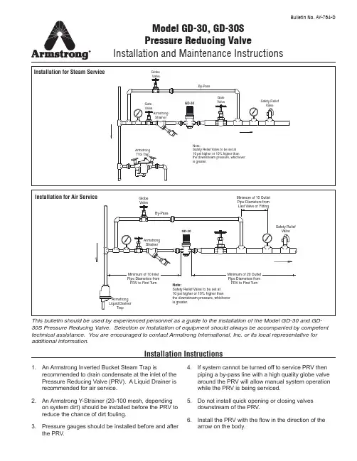
GlobeValveBy-PassMinimum of 10 OutletPipe Diameters fromLast Valve or FittingSafety ReliefValveMinimum of 20 OutletPipe Diameters fromPRV to First TurnGD-30ArmstrongStrainer Minimum of 10 Inlet Pipe Diameters fromPRV to First Turn ArmstrongLiquid DrainerTrap Note:Safety Relief Valve to be set at10 psi higher or 10% higher thanthe downstream pressure, whichever is greater.Model GD-30, GD-30SPressure Reducing ValveInstallation and Maintenance InstructionsThis bulletin should be used by experienced personnel as a guide to the installation of the Model GD-30 and GD-30S Pressure Reducing Valve. Selection or installation of equipment should always be accompanied by competent technical assistance. You are encouraged to contact Armstrong International, Inc. or its local representative for additional information.Bulletin No. AY-764-DInstallation Instructions1. An Armstrong Inverted Bucket Steam Trap isrecommended to drain condensate at the inlet of the Pressure Reducing Valve (PRV). A Liquid Drainer is recommended for air service.2. An Armstrong Y-Strainer (20-100 mesh, dependingon system dirt) should be installed before the PRV to reduce the chance of dirt fouling.3. Pressure gauges should be installed before and afterthe PRV.4. If system cannot be turned off to service PRV thenpiping a by-pass line with a high quality globe valve around the PRV will allow manual system operation while the PRV is being serviced.5. Do not install quick opening or closing valvesdownstream of the PRV.6. Install the PRV with the fl ow in the direction of thearrow on the body.Installation for Steam ServiceInstallation for Air ServiceGD-30Note:Safety Relief Valve to be set at10 psi higher or 10% higher thanthe downstream pressure, whicheveris greater.Safety ReliefValveGateValveBy-PassArmstrongTVS TrapArmstrongStrainerGateValveGlobeValve2Troubleshooting Guide1. Close the gate valves before and after the pressurereducing valve. Open the globe valve slowly in the bypass line and blow down the inlet piping. Adjust the opening of the bypass valve so the safety valve does not blow. After blowing the system down, close the bypass valve.2. Slowly open the inlet side gate valve to the fully openposition, and partially open the outlet valve so only a small amount of steam or air can pass.Start-Up and Adjustment ProceduresImproper adjustment of the pressure reducing valve may cause hunting, scale problems, water hammer, etc., and damage to the valve itself. Damaged pressure gauges, leakage or opening of a bypass valve, or clogging of an inlet strainer may cause problems similar to that of a malfunctioning reducing valve.Adjust the valve as follows:3. To increase the downstream pressure, place yourhand on the top of the adjusting handle and pull vertically up. When in the fully up position turn the handle clockwise until the desired pressure is obtained on the downstream pressure gauge.4. Release the handle and it will automatically retractwhich will lock the adjusting handle in place.5. Slowly open the outlet valve to the fully open position.ProblemCausesSolutionsThe desired pressure cannot be obtained.The inlet pressure is too low or high.Change the pressure to the appropriate level.The sensing port of the outlet pressure is clogged with foreign matter.Disassemble and clean the sensing port.The valve size is smaller than what is required.Change the valve size to the appropriate one.The adjustment is not appropriate.Readjust according to the adjustment procedure. (See start-up procedure)The inlet strainer is clogged by foreign substance.Disassemble and clean the strainer.The pressure gauge is not functioning properly.Replace the pressure gauge.The outlet pressure rises higher than the specified pressure.The valve or valve seat is contaminated by foreign substance.Disassemble and clean the valve or the seat.The by-pass valve is leaking.Repair or replace the by-pass valve.Abnormal noise is heard.The reducing ratio is excessively large.Reduce pressure by staging with second PRV.Water hammer (for steam service).Install a steam trap at the reducing valve inlet.There is a fast closing valve near the PRV.Provide as long a distance as possible between the two valves.3GD-30 1/2” - 1”Disassembly1. Eliminate pressure from inside the valve. Make sure the valve is completely free from pressure.2. Pull up and turn the handle (4) in the direction (counterclockwise) as shown on the nameplate of the handle to make the spring (12) free (not loaded).3. Remove the bolts (15) and take away the spring housing (2) (the handle cannot be disassembled).Take out the spring (12), bellows (10) and valve rod (8).4. Unscrew (counterclockwise) the cap (3) and take out the spring (13), screen (9) and valve (7) from the body (1).Reassembly1. Check all parts to make sure they are in goodcondition before putting back together.2. Lap valve (7) and valve seat (6) with 1000 grit lapping compound if needed to ensure no leakage.3. Reassemble in reverse order as disassembly.Note: Replace all gaskets where disassembly is required.Valve Seat (6)Cap (3)Gasket (16)Screen (9)Spring (13)Valve (7)Body (1)Valve Rod (8)E-Ring (20)Gasket (17)Bellows (10)Nameplate (23)Push Nut (22)(Adjusting Screw)Spring Pin (19)Split Pin (21)Spring Housing (2)Adjusting Screw (11)Spring (12)Spring Retainer (25)Flat Washer (18)Bolt (15)Handle (4)Spring (14)GD-30 1-1/2 - 2”Disassembly1. Eliminate pressure from inside the valve. Make sure the valve is completely free from pressure.2. Pull up and turn the handle (22) in the direction (counterclockwise) as shown on the nameplate of the handle to make the adjusting spring (13) free (not loaded).3. Remove the bolts (19) and take away the spring housing (2) (the handle cannot be disassembled. Take out the adjusting spring (13), bellows (9) and spindle (6).4. Unscrew (counterclockwise) the cap (3) and take out the main valve spring (7), screen (8) and spindle (5) from the body (1).Reassembly1. Check all parts to make sure they are in good condition before putting back together.2. Lap spindle (5) and valve seat (4) with 1000 gritlapping compound if needed to ensure noleakage.3. Reassemble in reverse order as disassembly.Note: Replace all gaskets where disassembly is required.Armstrong Pressure/Temperature Controls Group , 221 Armstrong Blvd., Three Rivers, Michigan 49093 - USA Ph: (269) 279-3600 Fax: (269) 273-8656armstrong Bulletin AY-764-D 3/11Printed in U.S.A.(Adjusting Screw)Small Spring Pin (24)Spring Housing (2)Rivet (25)Adjusting Screw (12)Bottom Spring Plate (10)Cap (3)Screen (8)Spindle (5)Valve Seat (4)Body (1)Spindle (6)E-Ring (16)Bellows Gasket (14)Bellows (9)Main Valve Spring (7)Cap Gasket (15)Adjusting Spring (13)Spring Plate (11)Flat Washer (18)Bearing (17)Bolts (19)Large Spring Pin (20)Handle (22)Bush Nut & Spring (23)Nameplate (24)Nameplate (24)。
The Piston-type Steam pressure reducing valveInstruction manualConfigurations:1 Lower cover 7 Piston ring 13 Diaphragm2 Body 8 Cylinder 14 Adjusting spring3 Main valve spring 9 Secondary valve spring 15 Valve cap4 Main valve seat 10 Upper bonnet 16 Adjusting screw5 Main valve 11 Secondary valve 17 Top cap6 Piston 12 Secondary valve seatMain performance and uses:Y43H is principally used in steam pipe, it can reduce the inlet pressure to a certain outlet pressure you need by adjusting thespring, when the flow and the pressure of the inlet varies, the outlet pressure can also remain within a certain range by the strength of the medium itself, but the differential pressure of the inlet and outlet must be equal or greater than 0.2MPa.Technical parameter:Working principal:When the pressure reducing valve leaves the factory, the adjusting spring is in uncompressed state, the main valve disc and secondary valve disc is in close position. When you want to use it, you can turn the adjusting screw clockwise; this can compress the adjusting spring, move the diaphragm down and then open the secondary valve disc, the medium also enters above the main valve seat through “a”hole to “b”hole, make the main valve disc open and then enters under the diaphragm through “c” hole. But when the downstream pressure is exceed the set pressure, the medium moves the diaphragm up and compresses adjustingspring, and then the secondary valve disc closes slowly, because the flow reduces, the downstream pressure get a new balance, on the other hand, when the downstream pressure is less than the set pressure, the gap between the main valve disc and the main valve seat increases and then the flow increases too and then make the downstream pressure get a new balance.Installation and maintenance:1.Clean the valve and the pipe line and remove the dirt beforeinstallation, at the same time the valve must be installed in horizontal direction, bracket is needed when the valve deadweight is heavy or vibration exists at the site.2.While installing, make sure the flow direction and thedirection marked on valve body is consistent, and a bypass pipe is usually required. When the valve size and the pipe size differ, reducer should be adopted. The installing site should have sufficient space for a convenient usage and maintenance.3.When the valve is put into use, the bypass globe valve mustbe opened, remove the condensate and the water vapor mixture in order to avoid the water hammer occurred by opening the valve. If there is no unusual phenomenonappears, you can turn the adjusting screw clockwise till getting the outlet pressure we need, then lock the nut and cover the top cap.4.A filter must be installed before the pressure reducing valvewhich prevents the impurities from getting into the valve. 5.There must be a straight pipe at least 600mm and 1000mmseperately before and after the pressure reducing valve.6.A water-vapor separator and a steam trap should be installedbefore the pressure reducing valve, atfter which a steam trap should also be installed.7.Pressure reducing valve should be kept in a dry room, both ofwhich should be blocked with blind plates. Do not keep in piles.8.If the pressure reducing valve will be kept for a long time, wemust check it regularly, clean up the dirt and spread some rust-proof oil on the movement part and the machined surface.9.If the outlet pressure is higher than the inlet pressure, wemust reset the pressure reducing valve as follows:①Shut off the upstream isolating valve;②Relief the downstream pressure;③Turn the adjusting screw counterclockwise, make it in a freepoisition.④ Open the upstream isolating valve slowly till full open. ⑤ Turn the adjusting screw clockwise, the outlet pressure rises slowly to the set value, then lock the adjusting screw. ⑥ If you adjust the pressure too high, you must readjust it from step 1 to step 5 (adjust from low pressure to high pressure only) Installation diagram:12 3 4 5 6 filter pressure gauge Pressurereducing valveGlobe valveSafety valveBypass pipe。
FISHERHSR减压阀说明FISHER HSR减压阀说明美国艾默生集团旗下的FISHER公司燃气输配技术掌握了世界领先的调压技术,其高质量标准已得到世界燃气行业的认可。
广州赫蒂能源设备有限公司是美国FISHER产品总代理商,拥有稳固的客户群,及专业的售后服务队伍。
我们已获得ISO9001质量管理系统认证,在可靠性、效率、安全操作及性价比方面为用户创造了巨大效益。
美国FISHER公司拥有一百多年生产优秀产品的历史,为天然气工业提供解决方案已历经三十余年;费希尔燃气输配技术是该领域公认的领先公司,其业务遍及全球。
FISHER HSR减压阀简介美国fisher原装进口HSR系列调压器,型号多样,广州赫蒂能源设备有限公司fisher总代理,HSR减压阀常用型号如下:HSR-CDHBLYN.HSR-CHHBLYN.HSR-CHJBLYN.HSR-CHGBLYN.H SR-CHCBLYN.HSR-CDBBMYN.HSR-CHGBMYN.HSR-BBBAMYY. HSR-BFFAMYN.HSR-CDBBMYY.HSR-CHJBLYN.HSR-BBBBLYN. HSR-BHBAMYN.HSR-CDCALYN调压器FISHER HSR减压阀参数◆技术参数:进口压力可以达到2KG,出口压力可以,从1.5KPA-12KPA都可以选择;流量液化气50KG(详情咨询代理--壹捌零贰柒叁柒陆壹捌肆。
零贰零叁贰叁柒伍捌叁陆);口径为DN25(一寸);FISHER HSR减压阀描述◆制作精良、调压稳定、范围广、可靠性精度高;◆适用于我国燃气行业和工厂供气,现有一级、二级、单段调压器供应,美国高稳定性的HSR调压器具有内部的微放散的功能;◆它的口径有:DN25*25气体的温度从零下29度到71度都适合!其性能的稳定性,安全性都非常的出色!调压精确,外观美观!是二级调压中运用较广泛的FISHER二级调压器!FISHER HSR减压阀安装方式安装前需对管道进行吹扫,将管道内灰尘杂质吹扫干净,以免杂质进入阀腔内部,导致调压器不能正常工作。
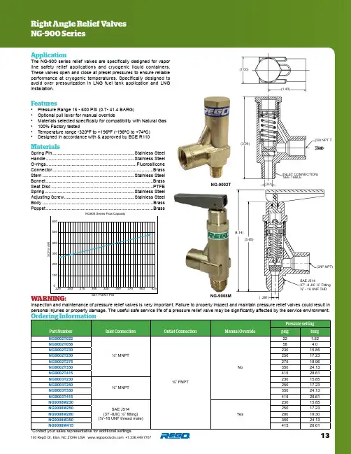
13100 RegO Dr. Elon, NC 27244 USA +1.336.449.7707ApplicationThe NG-900 series relief valves are specifically designed for vapor line safety relief applications and cryogenic liquid containers. These valves open and close at preset pressures to ensure reliable performance at cryogenic temperatures. Specifically designed to avoid over pressurization in LNG fuel tank application and LNG installation.Features• Pressure Range 15 - 600 PSI (0.7- 41.4 BARG)• Optional pull lever for manual override• Materials selected specifically for compatibility with Natural Gas • 100% Factory tested• Temperature range -320ºF to +196ºF (-196ºC to +74ºC)•Designed in accordance with & approved by ECE R110Right Angle Relief Valves NG-900 SeriesOrdering InformationMaterialsSpring Pin ................................................................Stainless SteelHandle .....................................................................Stainless Steel O-rings .......................................................................Fluorosilicone Connector ...............................................................................Brass Stem ........................................................................Stainless Steel Bonnet ....................................................................................Brass Seat Disc ................................................................................PTFE Spring ......................................................................Stainless Steel Adjusting Screw .......................................................Stainless Steel Body .......................................................................................Brass Poppet ....................................................................................BrassPart NumberInlet ConnectionOutlet ConnectionManual OverridePressure settingpsig barg NG9002T022¼” MNPT ⅜” FNPTNo22 1.52NG9002T05858 4.0NG9002T23023015.85NG9002T25025017.23NG9002T27527518.96NG9002T35035024.13NG9002T41541528.61NG9003T230⅜” MNPT23015.85NG9003T25025017.23NG9003T35035024.13NG9003T41541528.61NG9008M230SAE J514(37˚-8JIC ½” fitting)(¾”-16 UNF thread male)Yes23015.85NG9008M25025017.23NG9008M28028019.30NG9008M35035024.13NG9008M41541528.61NG-9002TWARNING:Inspection and maintenance of pressure relief valves is very important. Failure to properly inspect and maintain pressure relief valves could result in personal injuries or property damage. The useful safe service life of a pressure relief valve may be significantly affected by the service environment.NG-9008M*Contact your sales representative for additional settings.100200300400500600225250275300325350375400425S C F M A I RSET POINT PSING900 Series Flow Capacity(3/8" NPT)(2.00)(1.40)(3.65)(4.14)( .281)SAE J51437° -8 JIC ½” Fitting ¾” - 16 UNF THD(3.06)(3/8 NPT THD)(INLET CONNECTION)SEE TABLE(1.40)(.281)(3.06)(1.00)(3/8 NPT THD)(INLET CONNECTION)SEE TABLE(1.40)(.281)。
67CFR过滤减压阀说明书
67CFR过滤减压阀的使用说明如下:
该阀门通常用于向气动和电气动控制器和为其他仪器提供降低且持续受控的压力。
在流体控制行业,该阀门通常安装在控制阀的中间部位,为工业流体控制服务提供保障和降低压力。
此外,阀门还有如下功能:
1.过滤功能:可以过滤流体中的杂质,保证流体的清洁度。
2.调压功能:可以根据需要对流体进行调压,使流体的压力保持在所
需的范围内。
需要注意的是,对于这类阀门,一定要遵循操作规程,并且在使用过程中,应定期进行检查和维护,以保证其正常工作和延长使用寿命。
这个阀门的保养方法主要包括以下几个方面:
1.定期检查:定期对阀门进行检查,包括阀门的外观、密封件、阀
芯等部件,确保其没有损坏或磨损。
2.保持清洁:在操作过程中,流体可能会在阀门内部或外部留下杂
质或污垢,需要定期进行清洁。
3.润滑:对于需要润滑的部位,要定期进行润滑,防止出现卡滞或
磨损。
4.更换易损件:一些阀门在使用过程中,其内部的密封件、阀芯等
部件可能会出现磨损或老化,需要及时进行更换。
5.定期校准:如果阀门需要进行高精度的调节,需要定期进行校准,
确保其调节精度符合要求。
6.存储环境:在阀门不使用时,要将其存储在干燥、通风良好、无
阳光直射的地方,避免潮湿或高温环境。
7.定期保养:根据阀门的使用情况和制造商的推荐,定期进行全面
的保养,包括清洗、检查、更换部件等。

原版操作手册的译本© 2020 Festo SE & Co. KG 保留一切权利1适用文件有关产品的所有可用文件 è 。
2安全2.1安全注意事项–本装置在规定的运行条件下可应用于爆炸性气体环境 1 区和 2 区以及爆炸性粉尘环境 21 区和 22 区。
制造商声明 è /sp 。
–仅在原装状态下使用产品,请勿擅自进行改动。
–请仅在技术状态完好的情况下使用本产品。
–只能在潜在爆炸性区域以外执行所有作业。
–请注意产品标签上的说明。
–注意使用地的环境条件。
–通过将压缩空气吹过软管来清除进气管路中的颗粒。
借此可防止设备过早失效或异常磨损。
–通过压力表接口旁的固定孔或固定角架上的孔将设备接地。
2.2按规定使用过滤减压阀 PCRP 按照规定将其下游管路中的压缩空气调节至设定的输出压力。
过滤减压阀 PCRP 可消除压力波动。
输出压力 P2 可在压力调节范围内进行调节 è 12.2 技术参数,气动部分2.3专业人员的资质仅允许由具备资质的专业人员进行安装、调试、保养及拆卸。
专业人员必须掌握气动控制系统安装的专业知识。
2.4介质仅使用符合规格说明的介质 è 12.2 技术参数,气动部分。
3详细信息–附件 è /catalogue 。
–备件 è /spareparts 。
4服务若有技术问题,请联系 Festo 公司在您所在地的联系人 è 。
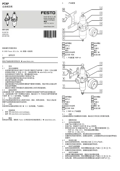
5产品配置1调节螺丝2排气口3气接口输出4流动方向说明5压力表 PAGN6排水螺丝7滤杯8气接口输入9螺钉 M510安装支架Fig. 1 产品配置 PCRP-641调节螺丝2排气口3气接口输出4流动方向说明5压力表 PAGN6排水螺丝7滤杯8气接口输入 9螺钉 M410安装支架Fig. 2 PCRP-44 产品配置5.1功能过滤减压阀除去污染颗粒和冷凝液。
输出压力可在压力范围内设置。
6装配和安装6.1安装过滤减压阀–注意产品上的箭头方向 4。

使用说明书减压阀宏源自动化仪表有限公司概述减压阀(Reducing valve)是采用控制阀体内的启闭件的开度来调节介质的流量,将介质的压力降低,同时借助阀后压力的作用调节启闭件的开度,使阀后压力保持在一定范围内,在进口压力不断变化的情况下,保持出口压力在设定的范围内,保护其后的生活生产器具。
按结构形式可分为膜片式、弹簧薄膜式、活塞式、杠杆式和波纹管式;按阀座数目可人为单座式和双座式;按阀瓣的位置不同可分为正作用式和反作用式。
第一章 产品技术参数一、工作原理蒸汽减压阀是采用控制阀体内的启闭件的开度来调节介质的流量,将介质的压力降低,同时借助阀后压力的作用调节启闭件的开度,使阀后压力保持在一定范围内,在进口压力不断变化的情况下,保持出口压力在设定的范围内,保护其后的生活生产器具。
本类阀门在管道中一般应当水平安装。
蒸汽减压阀是气动调节阀的一个必备配件,主要作用是将气源的压力减压并稳定到一个定值,以便于调节阀能够获得稳定的气源动力用于调节控制。
蒸汽减压阀的工作由阀后压力进行控制。
当压力感应器检测到阀门压力指示升高时,减压阀阀门开度减小;当检测到减压阀后压力减小,减压阀阀门开度增大,以满足控制要求。
蒸汽减压阀—该阀门的减压比必须在一定程度上高于系统值;即使在最大或者最小流量时它也应该能够对正作用或者反作用控制信号做出响应。
这些阀门应该针对有用控制范围选择,即最大流量的20%到80%。
正常为等比型或者具有等比特性。
活塞式减压阀工作原理:减压阀出厂时,调节弹簧处于未压缩状态,此时主阀瓣和副阀瓣处于关闭状态,使用时按顺时针方向转动调节螺钉,压缩调节弹簧,使膜片下移顶开副阀瓣,介质由a孔通过副阀座到b孔进入活塞上方,活塞在介质压力作用下,向下移动推动主阀瓣离开主阀座,使介质流向阀后,同时由c孔进入膜片下方,当阀后压力超过调定压力时,推动膜片上移压缩调节弹簧。
副阀瓣随之向关闭方向移动,使流入活塞上方的介质减小,压力也随之下降,此时主阀瓣在主阀瓣弹簧力的推动下上移,使主阀瓣与主阀座的间隙减小,介质流量随之减少,使阀后压力随之下降到的新的平衡,反之当阀后压力低于调定压力时,主阀瓣和主阀座间隙增大,介质流量随之增加,使阀后压力随之增高达到新的平衡。
减压阀
中
文
说
明
书
本手册仅供参考
Rev. 8/14/12
Ⅰ.PRV-71H 减压阀说明
美国海卓PRV-71H系列减压阀用于减小和控制此阀下游的气体压力。
PRV-71H 是为氯气或二氧化硫专门设计。
通过手动来设置和控制,使出口达到固定的压力。
减压阀是通过调节一个压缩的弹簧高度来控制出口的压力达到预定的水平。
配有排空连接以防膜片破裂。
Ⅱ.减压阀用途
PRV-71H用于:
1.防止阀下游的气体液化
2.保护设备不承受过大的压力
3.防止下游压力波动
Ⅲ.减压阀技术参数
主要参数:
最大进口压力:300psig(21 bar)
最高操作温度:225℉(107℃)
最低操作温度:-15℉(-26℃)
进/出口接口:3/4”NPT螺纹连接
排空接口:1/4”NPT螺纹连接
安装方式:内联或墙壁支架安装
最大投加能力(氯气或二氧化硫):8000PPD(160kg/h)
主要材质
外壳可拆卸以方便维护。
1.机械加工碳钢阀体
2.ECTFE(海拉尔)双膜片
3.PTFE(特氟隆)阀座
4.PVDF(Kynar)阀塞
下游压力超过控制压力的设置值,膜片就会关闭阀,关闭气体流动。
型号:PRV-71H-(气体种类)
CL2=氯气
SO2=二氧化硫
尺寸及重量:
总高:7.875”(200mm)
总宽:6”(152mm)
重量:16 lbs(5.9kg)。
原版操作手册的译本适用文件有关产品的所有可用文件è /pk。
2安全性2.1规定用途过滤减压阀 PCRP 将后续支线中的压缩空气调节至设置的输出压力。
PCRP 由此消除输出压力波动。
可以将输出压力 p2 设置在压力调节的范围内è 11 技术参数。
2.2一般安全信息–在爆炸性气体环境中,可以在规定的工作条件下在区域 1、2 使用该设备。
在爆炸性粉尘环境中,可以在规定的工作条件下在区域 21、22 使用该设备。
有关声明,请登录è 查看–本产品仅可在原装状态下使用,未经授权不得擅自修改。
–仅可在最佳技术条件下,使用该产品。
–在有爆炸危险的区域外执行所有作业。
–遵守所有适用性国家和国际法规。
–遵守产品标记上的说明。
–考虑使用地点的环境条件。
–将这些操作指南中指定的最大值与实际使用进行比较(例如,压力、扭矩)。
仅当遵守载荷范围时,才可以根据相关的安全准则使用该产品。
–用压缩空气吹管道,清除供应线中的污垢颗粒。
这样就能防止设备过早损坏或严重磨损。
–本产品仅可在原装状态下使用,不得擅自改动。
–通过压力表端口附近的安装孔或安装支架上的孔进行设备接地。
2.3介质–仅根据说明使用介质è 11 技术参数3服务如果有任何技术问题,请联系区域内的 Festo 联系人è 4附件附件:è /catalogue5产品总览5.1产品派生型5.1.1环境温度 T18:-20 °C … +80 °C接头型号订货号PCRP-64-N14-7-C-R1-M-T184787799PCRP-64-N14-12-C-R1-M-T184787800PCRP-64-N14-7-E-R1-M-T184787801NPT ¼"PCRP-64-N14-12-E-R1-M-T184787802PCRP-64-G14-7-C-R1-M-T184787803PCRP-64-G14-12-C-R1-M-T184787804PCRP-64-G14-7-E-R1-M-T184787805G ¼"PCRP-64-G14-12-E-R1-M-T184787806PCRP-64-N12-7-C-R1-M-T184787807PCRP-64-N12-12-C-R1-M-T184787808PCRP-64-N12-7-E-R1-M-T184787809NPT ½"PCRP-64-N12-12-E-R1-M-T184787810PCRP-64-G12-7-C-R1-M-T184787811PCRP-64-G12-12-C-R1-M-T184787812PCRP-64-G12-7-E-R1-M-T184787813G ½"PCRP-64-G12-12-E-R1-M-T184787814Tab. 15.1.2环境温度 T19:-60 °C - +80 °C接头型号订货号PCRP-64-N14-7-C-R1-M-T195394665PCRP-64-N14-12-C-R1-M-T195394666PCRP-64-N14-7-E-R1-M-T195394667NPT ¼"PCRP-64-N14-12-E-R1-M-T195394668PCRP-64-G14-7-C-R1-M-T195394669PCRP-64-G14-12-C-R1-M-T195394670PCRP-64-G14-7-E-R1-M-T195394671G ¼"PCRP-64-G14-12-E-R1-M-T195394672PCRP-64-N12-7-C-R1-M-T195394673PCRP-64-N12-12-C-R1-M-T195394674PCRP-64-N12-7-E-R1-M-T195394675NPT ½"PCRP-64-N12-12-E-R1-M-T195394676PCRP-64-G12-7-C-R1-M-T195394677PCRP-64-G12-12-C-R1-M-T195394678PCRP-64-G12-7-E-R1-M-T195394679G ½"PCRP-64-G12-12-E-R1-M-T195394680Tab. 25.2功能过滤减压阀 PCRP 清除污垢粒子和冷凝水。
毕业设计(论文)说明书题目:减压控制阀的设计系名机械工程系专业机械设计制造及其自动化学号6012201230学生姓名周翔指导教师朱家玲2016年5月20日摘要随着工业技术的发展,液压系统在当今机械领域用途越来越广泛,各种大、中、小型液压设备中,液压减压阀是系统中的一个关键性的压力控制元件,它们的性能和寿命在很大程度上决定着整个液压系统的平稳性和工作能力。
设计中对减压阀结构进行了探讨,并且比较了两种方案的优劣特点,选择了管式螺纹连接定值输出减压阀。
在现有的减压阀基础上通过改变主阀芯的材料,从而提高减压阀的灵敏度,使产品在满足设计条件要求的情况下,更加经济合理化。
在这次毕业设计中主要参考了DR50型先导式减压阀的相关产品的结构和技术参数,并以其为基础,重新设计了先导式定值输出液压减压阀阀芯的结构参数,通过计算和不断优化使减压阀的部分或整体性能有所提高完善。
关键词:先导式减压阀;管式连接;阀芯结构参数AbstractAlong with the development of the technology industry, Hydraulic system in tod- ay's machinery field use more and more widely, In all the big or small hydraulic equi- pment, Hydraulic pressure reducing valve is system of a key pressure control compo- nents.This design mainly in the market today of the pressure reducing valve for the fo- undation, Pilot type setting value output pressure reducing valve design. In the gradu- ation design process adopted some of the pressure reducing valve about new technolo- gy and new ideas, And used topilot type setting value output pressure reducing valve design, In the design of pressure reducing valve structure were discussed.In the graduation design main reference the forerunner of the pressure reducing valve DR50 type of related products structure and technical parameters, And as the f- oundation, To guide the design of hydraulic pressure reducing valve setting value ou- tput valve core structure parameters, Through calculation and continuous optimization of the pressure reducing valve to part or whole performance improved perfect.Key words:Pilot Operated Reducing Valves;Tube Type Conjunction;The Valve Core Structure Parameters目录第一章引言 (1)第二章减压阀 (3)2.1 减压阀的简介 (3)2.2 定值减压阀 (3)2.3 定比减压阀 (5)2.4 定差减压阀 (6)2.5 我国引进的德国力士乐公司压力阀系列 (7)第三章设计方案的分析与选定 (9)3.1 设计的目的及范围 (9)3.2 设计的任务要求 (9)3.3 设计的总体思路 (9)3.4 设计方案的对比与确定 (10)第四章减压阀的结构设计及计算 (12)4.1 减压阀的设计内容 (12)4.2 减压阀的设计步骤 (12)4.2.1 主要结构尺寸的初步确定 (12)4.2.2 主阀弹簧的设计 (14)4.2.3 先导阀弹簧的设计计算 (17)第五章减压阀结构材料的选择及回油路的设计205.1 减压阀主要构件的材料选择 (20)5.1.1 阀体(壳体)的材料选择 (20)5.1.2 阀芯与阀套的材料选择 (20)5.1.3 先导式减压阀的远程控制口K的用途 (20)5.1.4 液压阀主要构件加工工艺 (20)5.2 减压阀回油路的设计 (21)5.2.1 减压回路的工作原理 (21)5.2.2 减压阀设计应该注意事项 (22)5.2.3 减压阀常见的故障及诊断排除 (22)第六章减压阀的性能指标及造型 (25)6.1 减压阀的主要静态性能指标 (25)6.2 减压阀的动态性能 (26)6.3 减压阀的设计造型图 (27)第七章结论 (29)参考文献 (30)外文资料中文译文致谢第一章引言液压技术在功率密度、结构组成、响应速度、调速保护、过载保护、电液整台等方面都具有一定的优势,使其成为现代传动的重要技术手段和不可替代的关键基础技术之一,这些应用已经遍及了国民经济各个领域。
Series D1FVGeneral DescriptionSeries D1FV proportional pressure reducing valves areavailable with and without onboard electronics (OBE).D1FV OBEThe digital onboard electronics is situated in a robustmetal housing, which allows the usage under roughenvironmental conditions.The nominal values are factory set. The cable forconnection to a serial RS-232 interface is available asaccessory.D1FV for External ElectronicsThe parameters can be saved, changed and dupli-cated in combination with the digital power amplifierPWD00A-400. The value parameters can be editedwith the common ProPxD software for both versions.The D1FV values control the pressure in the A- orB-ports using the barometric feedback principle.Features•Barometric feedback• 3 command options for D1FV OBE: ±10V, 4...20mA,±20mA•High repeatability from valve to valve•Low hysteresis•Manual override•Pressure ranges 25 Bar (363 PSI) and 45 Bar (653 PSI)Technical InformationD1FV*3 OBED1FVD1FV OBEFunction CFunction KFunction EThis product can expose you to chemicals including Lead, Nickel (Metallic), or 1,3-Butadiene which are known to the State of California to go to .Series D1FVOrdering Information ProportionalPressure Reducing Valve Spool TypeSize DIN NG6 CETOP 3 NFPA D031E02DPressure Range Spool PositionSolenoid Voltage 12V 2.2AKSpool / Body Design3ConnectorVSealProportional Control FDesign Series NOTE: Not required when ordering.Weight: OffboardD1FV 2.2 kg (4.9 lbs.)Code DescriptionW*Connector as per DIN 185301-803 without plug J*Connector DT04-2P "Deutsch"* Please order plugs separately. See Accessories.Please order plugs separately. See Accessories.Parametrizing cable OBE => RS-232 Item no. 409829231) Single solenoid always 0...+/-10V respectively 4...20mA.2)Factory set ± 10V on delivery.Bolt Kit:BK209 (4) 10-24x1.25BK375 (4) M5x30Weight: OnboardD1FV 2.9 kg (6.4 lbs.)ProportionalPressure Reducing Valve Spool TypeSize DIN NG6 CETOP 3 NFPA D031E02DPressure Range Spool PositionInputSignalSpool / Body Design3OptionsVSealProportional Control FDesign Series NOTE: Not required when ordering.D1FV Onboard Electronics D1FV Offboard Electronics Code Input Signal 1) Function Port OptionsF00...+/-10V 0...+10V > P-A6 + PE PotentiometersupplyG00...+/-20mA 0...+20mA > P-A 6 + PE —M00...+/-10V 0...+10V > P-B6 + PE PotentiometersupplyS0 4...20mA 12...20mA > P-A 6 + PE—W5 2)0...+/-10V4...20mA 0...+/-20mA0...+10V > P-A 12...20mA > P-A 0... 20mA > P-A 11 + PE Potentiometer supply & commandpreset channelCode Description N Nitrile V FluorocarbonCode DescriptionN Nitrile V FluorocarbonSeries D1FV (Offboard Electronics)SpecificationsWith electrical connections the protective conductor (PE W) must be connected according to the relevant regulations.Series D1FVBlock Diagrams — WiringCode W511 + PE acc. to EN 175201-804Code F0, M06 + PE acc. to EN 175201-804Code G0, S06 + PE acc. to EN 175201-804Series D1FV Technical Information Features• Simple editing of all parameters.• Storage and loading of optimized parameter adjustments.• Executable with all Windows ®operating systems fromWindows ®95 upwards.• Communication between PC and electronics via serialinterface RS-232.The valve electronics cannot be connected to a PC with a standard USB cable – this can result in damages of PC and/or valve electronics.Simple to use interface program. Download free of charge /euro_hcd → Services → downloadsProPxD Interface ProgramThe ProPxD software allows quick and easy setting of the digital valve electronics. Individual parameters as well as complete settings can be viewed, changed and saved via the comfortable user interface. Parameter sets saved in the non-volatile memory can be loaded to other valves of the same type or printed out for documentation purposes.The parametrizing cable may be ordered under item no. 40982923.Series D1FV (Offboard Electronics) Inch equivalents for millimeter dimensions are shown in (**)DimensionsD1FV*E D1FV*KD1FV*C with DT04-2P“Deutsch” Connector15.0。
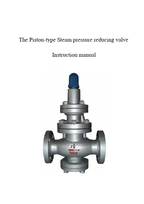
The Piston-type Steam pressure reducing valve
Instruction manual Configurations:
Main performance and uses:
Y43H is principally used in steam pipe, it can reduce the inlet pressure to a certain outlet pressure you need by adjusting the spring, when the flow and the pressure of the inlet varies, the outlet pressure can also remain within a certain range by the strength of the medium itself, but the differential pressure of the inlet and outlet must be equal or greater than 0.2MPa. Technical parameter:
Working principal:
When the pressure reducing valve leaves the factory, the adjusting spring is in uncompressed state, the main valve disc and secondary valve disc is in close position. When you want to use it, you can turn the adjusting screw clockwise; this can compress the adjusting spring, move the diaphragm down and then open the secondary valve disc, the medium also enters above the main valve seat through “a”hole to “b”hole, make the main valve disc open and then enters under the diaphragm through “c” hole. But when the downstream pressure is exceed the set pressure, the medium moves the diaphragm up and compresses adjusting spring, and then the secondary valve disc closes slowly, because the flow reduces, the downstream pressure get a new balance, on the other hand, when the downstream pressure is less than the set pressure, the gap between the main valve disc and the main valve seat increases and then the flow increases too and then make the downstream pressure get a new balance.
Installation and maintenance:
1.Clean the valve and the pipe line and remove the dirt before
installation, at the same time the valve must be installed in horizontal direction, bracket is needed when the valve deadweight is heavy or vibration exists at the site.
2.While installing, make sure the flow direction and the
direction marked on valve body is consistent, and a bypass pipe is usually required. When the valve size and the pipe size differ, reducer should be adopted. The installing site should have sufficient space for a convenient usage and maintenance.
3.When the valve is put into use, the bypass globe valve must
be opened, remove the condensate and the water vapor mixture in order to avoid the water hammer occurred by opening the valve. If there is no unusual phenomenon appears, you can turn the adjusting screw clockwise till getting the outlet pressure we need, then lock the nut and cover the top cap.
4.A filter must be installed before the pressure reducing valve
which prevents the impurities from getting into the valve. 5.There must be a straight pipe at least 600mm and 1000mm
seperately before and after the pressure reducing valve.
6.A water-vapor separator and a steam trap should be installed
before the pressure reducing valve, atfter which a steam trap should also be installed.
7.Pressure reducing valve should be kept in a dry room, both of
which should be blocked with blind plates. Do not keep in piles.
8.If the pressure reducing valve will be kept for a long time, we
must check it regularly, clean up the dirt and spread some rust-proof oil on the movement part and the machined surface.
9.If the outlet pressure is higher than the inlet pressure, we
must reset the pressure reducing valve as follows:
①Shut off the upstream isolating valve;
②Relief the downstream pressure;
③Turn the adjusting screw counterclockwise, make it in a free
poisition.
④Open the upstream isolating valve slowly till full open.
⑤Turn the adjusting screw clockwise, the outlet pressure rises
slowly to the set value, then lock the adjusting screw.
⑥If you adjust the pressure too high, you must readjust it from step 1 to step 5 (adjust from low pressure to high pressure only) Installation diagram:。