VEGA仪表安装详细说明
- 格式:ppt
- 大小:777.50 KB
- 文档页数:15
一 PLICSCOM显示调试模块设置1.1 概述功能/设置显示调试模块PLICSCOM用于测量显示、调整和测试,可安装于下列封装外壳和仪器中:●plics®系列传感器的所有单室壳体和双室壳体;●外置的显示调试单元VEGADIS61;从PLICSCOM的硬件版本…-01开始及其传感器,可以通过调试菜单设置背光显示。
硬件的版本号标示在PLICSCOM的标签上或传感器的电子部件中。
提示:此功能是用于带有安全许可的仪表,如:StEx、WHG或船用许可,以及FM、CSA等一些即将实施的国家专用许可。
备注:您可以在显示调试模块PLICSCOM的操作指引手册中获得详细的资料。
1.2 显示调试模块的安装装卸显示调试模块显示调试模块可随时装卸,装卸可带电操作,无需关闭供电电源。
安装步骤如下:1、旋开外壳面盖;2、把显示调试模块放入电子面板上(你可选择四种不同的方位,每个方位相差90°)3、压紧显示调试模块并顺时针转动,直至模块卡紧到位;4、装回带观察视窗的外壳面盖并旋紧。
拆卸方法则是上述步骤的反操作。
显示调试模块直接由传感器供电,无需连接额外的电源。
图26 显示调试模块安装示意图备注:如果您是在原有的VEGAPULS63上增加显示调试模块用于连续测量显示,将需要配置一个加高的带观察视窗的面盖。
1.3 系统调试图27 显示和调试部件1、液晶显示屏2、菜单编号显示3、调试按键按键功能●[OK] 按键:-返回到菜单首项-确认所选菜单-编辑参数-保存设置●[►]按键选择:-菜单选择-列出选项-位置编辑●[+]按键:-改变参数值●[ESC] 按键:-中断输入-返回上一层菜单系统调试传感器通过显示调试模块的四个按键作调整,液晶屏显示各个菜单选项,各个按键的功能如上所述。
在停止按键10分钟后,模块将会自动回复到显示测量值状态。
任何没有以[OK]键确认的设置将不会保存。
1.4 设置的步骤HART-Multidrop地址设置在HART-Multidrop模式(一个输入设置多个传感器),必须首先设置地址,然后才能作参数调整。
VEGA射空雷达液位计使用说明1.引言VEGA射空雷达液位计是一种通过雷达技术来测量液体或固体物料的液位的设备。
它具有精度高、适用范围广、可靠性强等特点,适用于各种工业领域,如化工、石油、食品等。
本使用说明书将介绍VEGA射空雷达液位计的安装、操作和维护等方面内容。
2.安装2.1安装位置选择根据测量要求,选择合适的安装位置。
应选择没有振动、震荡和腐蚀性气体的区域,以确保测量精确和设备的正常运行。
2.2安装方法按照安装图纸,将液位计安装在合适的位置。
确保设备垂直且与测量物料的液面平行。
注意紧固螺栓,以确保设备的固定和密封。
3.连接和设置3.1电缆连接将电缆连接到液位计的连接端子上。
确保连接稳固可靠,并注意电缆的防护等级要求。
3.2信号线连接根据需要,连接液位计的信号线到相应的仪表或控制系统上。
确保线路接触良好,信号传输准确可靠。
3.3参数设置根据实际需求,在仪表或控制系统中设置相应的参数,例如液位单位、量程范围等。
确保参数设置正确,以保证液位计的准确测量和报警功能的正常使用。
4.操作4.1启动和停止在保证相应的电源和系统连接的情况下,按下液位计的启动开关,设备将开始正常运行。
在需要停止设备时,关闭相应的电源和系统连接。
4.2备份电源液位计通常带有备份电源功能。
在主电源故障或断电时,备份电源将自动启动,确保设备的正常工作。
当主电源恢复后,备份电源将自动转为主电源。
4.3液位测量液位计将通过射空雷达技术测量液体或固体的液位。
它能够测量各种介质,如水、油、粉末等。
根据实际情况选择合适的测量模式,确保测量的准确性。
5.维护5.1定期检查定期检查液位计以确保其正常运行。
包括检查电缆连接是否松动、清理传感器、检查密封件是否完好等。
5.2清洁液位计的传感器表面可能会沾上污垢。
定期使用干净的布或软刷清洁传感器表面,以保证测量的准确性。
5.3校准根据需要,定期校准液位计,以确保测量结果准确可靠。
校准可以通过仪表或控制系统进行,可以根据操作手册进行操作。
vega雷达物位计说明书第一章:引言1.1产品简介Vega雷达物位计是一种先进的仪器,用于测量液体、固体和粉粒状物料的物位。
它通过发射和接收雷达信号来确定物料的位移和高度。
这个说明书将帮助用户了解和正确使用Vega雷达物位计。
1.2主要特点- 高精度测量:Vega雷达物位计具有高精度的测量功能,可准确测量各种物料的物位。
- 可靠性:Vega雷达物位计采用先进的技术和材料,具有稳定性和耐用性。
- 轻松安装:Vega雷达物位计具有简单的安装过程,适用于不同类型的容器。
- 易于使用:Vega雷达物位计采用用户友好的界面,使用户可以轻松进行配置和操作。
- 多功能:Vega雷达物位计具有多种功能,如物料温度测量、反射强度调节和距离补偿等。
第二章:产品规格2.1外观和尺寸Vega雷达物位计外观典雅,尺寸为100mm×200mm×50mm,重量为1kg。
2.2技术指标-测量范围:0-20米- 准确度:±2mm-工作温度:-40°C至85°C-电源:220VAC或24VDC- 输出信号:4-20mA或Modbus RS485第三章:安装与操作3.1安装步骤1)在容器上选择一个合适的位置进行安装。
2) 使用提供的安装配件将Vega雷达物位计固定在容器上。
3)连接电源和信号线。
3.2配置与校准1) 打开Vega雷达物位计的电源。
2)进入配置模式,通过菜单进行参数设置,如温度单位、物料类型等。
3)进行校准,按照说明书中给出的步骤进行操作。
3.3操作与维护1) 使用人员应熟悉Vega雷达物位计的各项功能和操作方式。
2) 定期检查和维护Vega雷达物位计,确保其正常运行。
3) 避免将Vega雷达物位计暴露在恶劣的环境中,以免损坏设备。
第四章:故障排除4.1常见问题与解决方法-问题:无法正常启动解决方法:检查电源连接是否正确,重新插拔电源线。
-问题:测量结果不准确解决方法:检查安装是否正确,进行重新校准。
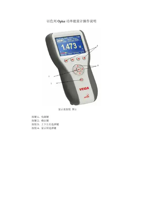
以色列Ophir功率能量计操作说明显示表按钮图1按键1,电源键按键2,确认键按钮3,上下左右选择键按钮4,显示屏选择键显示菜单图2,1,能量或功率量程选择2,波长选择3,功能菜单(在图3中将给出详细介绍)4,测试时间设置(时间越长波动越小,但是对较快的频率且能量变化较大的测量不利,建议默认设置)5,衰减片设置,OUT为带衰减片,IN为不带衰减片6,激光脉宽选择,有两个值可选,选择较小的值表示激光脉宽小于该值,选择较大的值表示激光脉宽大于较小的值,例如,有个表头有1ms和3ms两个脉宽,如果选择1ms,则表示要测量的激光脉宽小于1ms,脉冲宽度大于1ms,选择3ms。
7,更改显示屏幕颜色(7种颜色)8,功率/能量测试切换(华光公司订购的为能量探头,无此切换功能)9,显示探头型号和序列号设置菜单图31,能量或功率选择2,指针式显示3,设置一段时间测量,例如10秒内测量,时间到了就停止4,数据存储5,归一化显示6,测能量密度,需要输入光斑大小7,衰减设置8,测试上下限设置9,连接示波器设置10,系统参数11,清零12,校正设置(千万不要更改本设置,否则测量能量值不再准确)13,仪器参数备注:该显示表菜单会根据连接的探头不同而显示不同显示表接头图4 1,电源2,模拟输出3,探头接口4,电脑接口仪器使用步骤1.在不接探头的情况下,按下图1电源键“1”,约3秒开机。
2.在不连接探头的请款下开机并按图1中Zero清零,约1分钟后按save键完成后退出并关机。
3.关机后,连接所需要的探头,开机。
按图3中的Zero清零,完成后按save键存储。
回到图2所示的界面中,更改激光波长及能量量程(建议待测能量>10%能量量程)就可以开始测量。
4,完成后按图1电源键“1”关机。
软件使用注意事项:先安装光盘内软件,然后把表连接电脑。
具体操作见说明书。
注意事项:1.在开始使用能量计前,请先大概估算一下激光的能量密度是否会超过能量探头的损伤阈值(具体指标见探头参数),如果不好估算,可以先使用随探头所附的能量测试片测试一下激光,如果测试片没有被打坏,则可以使用能量探头进行测试。
vega雷达液位计说明书中文版Vega雷达液位计说明书中文版雷达液位计是一种先进的仪器设备,广泛应用于工业生产中的液体储存和流程控制。
本说明书将详细介绍Vega雷达液位计的特点、使用方法和注意事项,以帮助用户正确使用和维护该设备。
首先,Vega雷达液位计具有高精度和稳定性的特点。
它采用先进的雷达技术,能够准确测量各种液体的高度,并将数据传输到控制系统中。
其测量范围广泛,可适用于不同容器和工艺条件下的液位测量。
其次,Vega雷达液位计具有良好的抗干扰能力。
它能够有效地排除外界干扰信号,并保证测量结果的准确性。
同时,该设备还具有自动校准功能,能够根据环境变化自动调整测量参数,提高了系统的稳定性和可靠性。
使用Vega雷达液位计非常简便。
用户只需按照说明书中的步骤进行安装和调试即可。
在安装过程中,需要注意设备与容器之间的距离、安装位置以及电源接线等细节。
在调试过程中,用户需要根据实际情况设置测量范围和报警参数,以满足生产过程中的需求。
在使用Vega雷达液位计时,用户需要注意以下几点。
首先,设备应定期进行维护和保养,以确保其正常工作。
其次,设备应避免受到强磁场和高温环境的影响,以免影响测量精度和寿命。
最后,用户在操作设备时应注意安全事项,避免发生意外事故。
总之,Vega雷达液位计是一种高精度、稳定性强的液位测量设备。
它具有良好的抗干扰能力和自动校准功能,能够满足不同工艺条件下的液位测量需求。
使用该设备时需要注意安装、调试和维护等方面的细节,并遵守相关的安全规定。
通过正确使用和维护Vega雷达液位计,可以提高生产效率、降低成本,并确保生产过程的安全性和稳定性。

VEGASON 65安装操作手册
图1
1 物料满仓
2 物料空仓
3 物位计测量范围
4 测量基本参考点(从探头下沿开始计算,与物料满仓之间必须有一定距离)
图2
1 安装位置与仓壁最小距离为50MM
图3 为物位计在不同环境下的安装方法:
图3
图4 请按图示连接:
1 物位计电气单元
2 连接插头
3 物位计连接管
图5 物位计电气单元内部
图6 图6为物位计电子单元内部接线示意图
V——四线制4-20mA/HART
图7
图8 图7和图8为物位计外观尺寸图,请参照具体式样选择相应图片
注:本款物位计详细参数为
B——一体化带万向节
AS——DN50万向节法兰。
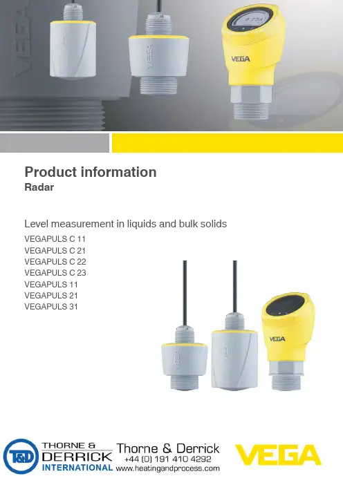
Product informationRadarLevel measurement in liquids and bulk solids VEGAPULS C 11VEGAPULS C 21VEGAPULS C 22VEGAPULS C 23VEGAPULS 11VEGAPULS 21VEGAPULS 3158365-EN-220218Contents1 Measuring principle ...............................................................................................................................................................................................32 T ype overview .........................................................................................................................................................................................................43 Instrument selection ..............................................................................................................................................................................................64 Mounting .................................................................................................................................................................................................................75 Electronics - T wo-wire 4 ... 20 mA ........................................................................................................................................................................96 Electronics - T wo-wire 4 ... 20 mA/HART ...........................................................................................................................................................107 Electronics - SDI-12 .............................................................................................................................................................................................118 Electronics - Modbus ...........................................................................................................................................................................................129 Adjustment ...........................................................................................................................................................................................................1310 Dimensions .. (14)T ake note of safety instructions for Ex applicationsPlease note the Ex specific safety information that you can find at and that comes with each instrument. In hazardous areas you should take note of the appropriate regulations, conformity and type approval certificates of the sensors and power supply units. The sen -sors must only be operated on intrinsically safe circuits. The permissible electrical values are stated in the certificate.Measuring principle58365-E N -2202181 Measuring principleMeasuring principleThe devices emit a continuous radar signal through their antennas. The emitted signal is reflected by the medium and received as an echo by the antenna.The frequency difference between the emitted and received signal is proportional to the distance and depends on the filling height. The determined filling height is converted into a respective output signal and output as measured value.80 GHz technologyThe 80 GHz technology used enables a unique focusing of the radar beam and a wide dynamic range of the radar sensors. The greater the dynamic range of a radar sensor, the wider its application spectrum and the higher its measurement reliability.AdvantagesNon-contact radar technology is characterized by extremely high meas -urement accuracy. The measurement is influenced neither by fluctuating product features nor by changing process conditions such as tempera -ture, pressure or strong dust generation. The user-friendly adjustment without vessel filling and emptying saves time.Input variableThe measured variable is the distance between the antenna edge of the sensor and the medium surface. The antenna edge is also the reference1 Reference plane2Measured variable, max. measuring range58365-EN-2202182 T ype overviewVEGAPULS C 11VEGAPULS C 21VEGAPULS C 22ApplicationsWater processing, pump stations, storm water overflow tank, level monitoring Water processing, pump stations, storm water overflow tank, flow measurement in open flumes, level monitoring Water processing, pump stations, storm water overflow tank, flow measurement in open flumes, level monitoring Max. measuring range 8 m (26.25 ft)15 m (49.21 ft)15 m (49.21 ft)Antenna/Material Integrated antenna system/PVDF encap -sulated Integrated antenna system/PVDF encap -sulated Integrated antenna system/PVDF encap -sulated Beam angle 8°8°8°Process fitting MaterialG1½, 1½ NPT , R1½PVDF G1½, 1½ NPT , R1½PVDF G1½, 1½ NPT , R1½PVDFConnection for mounting strapG1, 1 NPT , R1G1, 1 NPT , R1G1½, 1½ NPT , R1½ Process temperature -40 … +60 °C-40 … +140 °F)-40 … +80 °C(-40 … +176 °F)-40 … +80 °C(-40 … +176 °F)Process pressure -1 … +3 bar/-100 … +300 kPa (-14.5 … +43.51 psi)-1 … +3 bar/-100 … +300 kPa (-14.5 … +43.51 psi)-1 … +3 bar/-100 … +300 kPa (-14.5 … +43.51 psi) Deviation ≤ 5 mm ≤ 2 mm ≤ 2 mm Frequency range W-bandW-bandW-bandSignal output•T wo-wire 4 … 20 mA• T wo-wire 4 … 20 mA/HART • SDI-12• Modbus• T wo-wire 4 … 20 mA/HART • SDI-12• ModbusCommunication interface BluetoothBluetoothBluetoothIndication/Adjustment -/Via app on smartphone or tablet andBluetooth -/Via app on smartphone or tablet and Bluetooth-/Via app on smartphone or tablet and BluetoothApprovals 1)-• c-UL-us, EAC, RCM • ATEX/IEC • EAC/SEPRO• NEPSI/CCOE/TIIS/KOSHA •INMETRO/IA• c-UL-us, EAC, RCM • ATEX/IEC • EAC/SEPRO• NEPSI/CCOE/TIIS/KOSHA •INMETRO/IA1)Available or applied forT ype overview58365-E N -220218VEGAPULS C 23VEGAPULS 11VEGAPULS 21VEGAPULS 31Water processing, pump stations, storm water overflow tank, flow measurement in open flumes, level monitoring Water treatment, storage tanks in all industrial areas, plastic tanks (meas -urement through the tank wall)Water treatment, storage tanks in all industrial areas, plastic tanks (meas -urement through the tank wall)Water treatment, storage tanks in all industrial areas, plastic tanks (meas -urement through the tank wall)30 m (98.43 ft)8 m (26.25 ft)15 m (49.21 ft)15 m (49.21 ft)Integrated antenna system/PVDF en -capsulated Integrated antenna system/PVDF en -capsulated Integrated antenna system/PVDF en -capsulated Integrated antenna system/PVDF en -capsulated 4°8°8°8°-G1½, 1½ NPT , R1½PVDFG1½, 1½ NPT , R1½PVDFG1½, 1½ NPT , R1½PVDFG1, 1 NPT , R1G1½, 1½ NPT , R1½G1½, 1½ NPT , R1½G1½, 1½ NPT , R1½-40 … +80 °C (-40 … +176 °F)-40 … +60 °C -40 … +140 °F)-40 … +80 °C (-40 … +176 °F)-40 … +80 °C (-40 … +176 °F)-1 … +3 bar/-100 … +300 kPa (-14.5 … +43.51 psi)-1 … +3 bar/-100 … +300 kPa (-14.5 … +43.51 psi)-1 … +3 bar/-100 … +300 kPa (-14.5 … +43.51 psi)-1 … +3 bar/-100 … +300 kPa (-14.5 … +43.51 psi)≤ 2 mm ≤ 5 mm ≤ 2 mm ≤ 2 mm W-bandW-bandW-bandW-band• T wo-wire 4 … 20 mA/HART • SDI-12•Modbus•T wo-wire 4 … 20 mA•T wo-wire 4 … 20 mA/HART•T wo-wire 4 … 20 mA/HARTBluetoothBluetoothBluetoothBluetooth-/Via app on smartphone or tablet and Bluetooth-/Via app on smartphone or tablet and Bluetooth -/Via app on smartphone or tablet and BluetoothIntegrated display and adjustment unit/Via app on smartphone or tablet and Bluetooth• c-UL-us, EAC, RCM • ATEX/IEC • EAC/SEPRO• NEPSI/CCOE/TIIS/KOSHA •INMETRO/IA-• c-UL-us, EAC, RCM • ATEX/IEC • EAC/SEPRO• NEPSI/CCOE/TIIS/KOSHA •INMETRO/IA• c-UL-us, EAC, RCM • ATEX/IEC • EAC/SEPRO• NEPSI/CCOE/TIIS/KOSHA •INMETRO/IA58365-EN-2202183 Instrument selectionApplication areaThe radar sensors of the VEGAPULS 10, 20, 30 series described here are used for non-contact level measurement of liquids and bulk solids. They can be used in both simple and aggressive liquids. The sensors also measure light and heavy bulk solids absolutely reliably, both with strong dust and noise generation and independent of buildup or conden -sation.Device overview VEGAPULS C 11VEGAPULS C 11 is the ideal sensor for non-contact level measurement in simple applications where a high degree of protection is required. It is particularly suitable for use in water treatment, pumping stations, rain overflow basins and level monitoring.VEGAPULS C 21, C 22, C 23VEGAPULS C 21, C 22, C 23 are the ideal sensors for non-contact level measurement in simple applications where a high degree of protection is required. They are particularly suitable for use in water treatment,pumping stations and rain overflow basins, for flow measurement in open channels and level monitoring.VEGAPULS 11, 21, 31VEGAPULS 11, 21, 31 are the ideal sensors for non-contact level measurement in simple applications. They are particularly suitable for use in water treatment, storage tanks with acids, lyes and additives in all industrial areas, or for measuring levels in plastic tanks from the outside through the tank wall.Configuration and housing protection classesThe radar sensors of series VEGAPULS 10, 20, 30 are available in differ -ent designs, housing protection classes and connection techniques. The following illustrations show typical examples.1 Radar antenna2 Process fitting3 Electronics housing4 Counter nut5 Mounting thread 6Connection cableIP66/IP68 (3 bar)1 Radar antenna 2 Process fitting3 Electronics housing 4Cable outlet1 Radar antenna2 Electronics housing3 Counter nut4 Mounting thread 5Connection cable1 Radar antenna2 Process fitting3 Process seal4 Electronics housing5 Display and adjustment unit6Ventilation/pressure compensationMounting58365-E N -2202184 MountingInstallation positionMount the sensor in a position which is at least 200 mm (7.874 in) away from the vessel wall. If the sensor is installed in the center of dished or round vessel tops, multiple echoes can arise. However, these can be suppressed by an appropriate adjustment.In vessels with conical bottom it can be advantageous to mount the sen-sor in the centre of the vessel, as measurement is then possible down tothe bottom.Mounting examples gauge measurementThe following illustrations show mounting examples and possible meas -urement setups.Fig. 8: Gauge measurement river, sensor mounting on bridge pierFig. 9: Gauge measurement deep well, sensor mounting on lidMounting examples flow measurementThe following illustrations show mounting examples and possible meas -urement setups.max.gular flume1 Overfall orifice (side view)2 Upstream water3 T ailwater4 Overfall orifice (view from tailwater)58365-EN-220218max.flume; B = tightest constriction in the flume 1 Position sensor 2Venturi flumeElectronics - T wo-wire 4 … 20 mA58365-E N -2202185 Electronics - T wo-wire 4 … 20 mAVoltage supplyPower the instrument via an energy-limited circuit (power max. 100 W) acc. to IEC 61010-1.Specifications of the voltage supply:•Operating voltage –12 … 35 V DC• Permissible residual ripple–for U N 12 V DC (12 V < U B < 18 V): ≤ 0,7 V eff (16 … 400 Hz) –for U N 24 V DC (18 V < U B < 35 V): ≤ 1,0 V eff (16 … 400 Hz)Keep in mind the following additional factors that influence the operating voltage:• Lower output voltage of the power supply unit under nominal load (e.g. with a sensor current of 20.5 mA or 22 mA in case of fault signal)•Influence of additional instruments in the circuit (see load values in chapter " T echnical data " of the operating instructions of the respec -tive instrument)Connection cable The instrument is connected with standard two-wire cable.ConnectionWire colourFunctionPolarity 1Brown Voltage supply, signal output +2BlueVoltage supply, signal output-1Voltage supply, signal output58365-EN-2202186 Electronics - T wo-wire 4 … 20 mA/HARTVoltage supplyPower the instrument via an energy-limited circuit (power max. 100 W) acc. to IEC 61010-1.Specifications of the voltage supply:•Operating voltage –12 … 35 V DC• Permissible residual ripple–for U N 12 V DC (12 V < U B < 18 V): ≤ 0,7 V eff (16 … 400 Hz) –for U N 24 V DC (18 V < U B < 35 V): ≤ 1,0 V eff (16 … 400 Hz)Keep in mind the following additional factors that influence the operating voltage:• Lower output voltage of the power supply unit under nominal load (e.g. with a sensor current of 20.5 mA or 22 mA in case of fault signal)•Influence of additional instruments in the circuit (see load values in chapter " T echnical data " of the operating instructions of the respec -tive instrument)Connection cableThe instrument is connected with standard two-wire cable. If electro -magnetic interference is expected which is above the test values of EN 61326-1 for industrial areas, shielded cable should be used.Shielded cable generally necessary in HART multidrop mode.ConnectionWire colourFunctionPolarity 1Brown Voltage supply, signal output +2BlueVoltage supply, signal output -3Shielding1 Voltage supply, signal output2Plug connector for display and adjustment unitElectronics - SDI-1258365-E N -2202187 Electronics - SDI-12Voltage supplyThe device is supplied with power via an SDI-12 datalogger.Power the instrument via an energy-limited circuit (power max. 100 W) acc. to IEC 61010-1.Specifications of the voltage supply:•Operating voltage –9 … 32 V DC• max. number of sensors –32Connection cableThe instrument is connected with standard three-wire cable withoutshielding. If electromagnetic interference is expected which is above the test values of EN 61326-1 for industrial areas, shielded cable should be used.ConnectionWire colourFunction Polarity 1Brown Voltage supply +2Blue Voltage supply -3WhiteSDI Data +4Shielding58365-EN-2202188 Electronics - ModbusVoltage supplyThe operating voltage and the digital bus signal are routed via separate two-wire connection cables.Power the instrument via an energy-limited circuit (power max. 100 W) acc. to IEC 61010-1.Specifications of the voltage supply:•Operating voltage –8 … 30 V DC• max. number of sensors –32Connection cableThe instrument is connected with standard two-wire, twisted cable suit -able for RS 485. If electromagnetic interference is expected which is above the test values of EN 61326 for industrial areas, shielded cable should be used.Make sure that the entire installation is carried out according to the Field -bus specification. In particular, make sure that the bus is terminated with suitable terminating resistors.ConnectionWire colourFunction Polarity 1Brown Voltage supply +2Blue Voltage supply -3Black Modbus signal D0+4WhiteModbus signal D1-5ShieldingAdjustment58365-E N -2202189 Adjustment9.1Wireless adjustmentDevices with integrated Bluetooth module can be adjusted wirelessly via standard adjustment tools:• Smartphone/tablet (iOS or Android operating system)PC/notebook (Windows operating system)Bluetooth LE1 Sensor2 Smartphone/T ablet3 PC/Notebook9.2Adjustment via the signal cableDevices with signal output 4 … 20 mA/HART can also be operated via a signal cable. This is done via an interface adapter and a PC/notebook using DTM/PACTware.1 Sensor2 HART resistance 250 Ω (optional depending on evaluation)3 Connection cable with 2 mm pins and terminals4 Voltage supply5 Interface adapter VEGACONNECT9.3Local adjustmentThe integrated display and adjustment unit is used for on-site adjustment of VEGAPULS 311 LC display2Adjustment keys58365-EN-22021810 Dimensions1 Thread G1½2 Thread 1½ NPT 3Thread R1½1 Thread G1½2 Thread 1½ NPT3 Thread R1½1 Thread G1½2 Thread 1½ NPT 3Thread R1½1 Thread G1½2 Thread 1½ NPT3 Thread R1½Dimensions58365-E N -2202181 Sensor holder 1"2Sensor holder 1½"1 Sensor holder 1"2Sensor holder 1½"The listed drawings represent only an excerpt of the available ver -sions and mounting possibilities. Y ou can find more drawings at /downloads under " Drawings ".VEGA Grieshaber KGAm Hohenstein 113 77761 Schiltach 5 8 3 6 5 -E N -2 2 0 2 1 8All statements concerning scope of delivery, application, practical use and operating conditions of the sensors and processing systems correspond to the information available at the time of printing.Subject to change without prior notice© VEGA Grieshaber KG, Schiltach/Germany 2022Phone +49 7836 50-0E-mail:****************。
vega料位计说明书一、设备简介VEGA料位计是一种精确测量固体料位高度的仪器。
它广泛应用于各种工业环境,如化工、食品、制药等,用于监测和控制在料仓、输送带或其他容器中的物料高度。
VEGA料位计以其高效、可靠和精确的性能,为用户提供了方便快捷的测量方式。
二、工作原理VEGA料位计基于回声测量原理工作,通过向物料表面发出超声波信号,并测量反射回来的信号时间,计算出料位的高度。
由于超声波在空气中的传播速度几乎不受温度、压力等环境因素的影响,因此VEGA料位计具有很高的测量精度和稳定性。
三、安装步骤1. 确定安装位置:选择一个能反映物料真实高度的位置,避开进料口、出料口及物料堆积处。
2. 安装固定:使用适当的紧固件将VEGA料位计固定在选定的位置。
3. 连接电缆:将VEGA料位计的电缆连接到相应的电源和数据采集设备上。
4. 调试校准:根据使用的物料特性和环境条件,对VEGA料位计进行校准和调试。
四、操作说明1. 启动设备:接通电源,打开电源开关,设备开始工作。
2. 数据读取:通过连接的数据采集设备,可以实时读取和记录料位的高度数据。
3. 异常处理:当设备出现异常或测量误差较大时,应及时检查设备的工作状态和校准情况。
五、维护与保养1. 定期清洁:定期清洁超声波传感器表面,保持清洁无杂物,以防止对测量结果产生影响。
2. 校准检查:定期对VEGA料位计进行校准,以确保测量的准确性。
3. 更换电池:当电池电量低时,应及时更换电池,以保证设备的正常运行。
六、常见问题及解决方案1. 测量不准确:可能是由于传感器表面污染或物料特性影响,需要清洁传感器表面或检查物料特性。
2. 无数据显示:可能是电源故障或数据采集设备连接问题,应检查电源和连接线路。
七、技术参数1. 测量范围:根据不同型号和规格,测量范围在几米至几十米不等。
2. 精度:±1% 或更高。
3. 工作温度:一般可在-20℃至+60℃之间工作。
4. 电源:DC12V 或AC24V,具体视型号而定。
一 PLICSCOM显示调试模块设置1.1 概述功能/设置显示调试模块PLICSCOM用于测量显示、调整和测试,可安装于下列封装外壳和仪器中:●plics®系列传感器的所有单室壳体和双室壳体;●外置的显示调试单元VEGADIS61;从PLICSCOM的硬件版本…-01开始及其传感器,可以通过调试菜单设置背光显示。
硬件的版本号标示在PLICSCOM的标签上或传感器的电子部件中。
提示:此功能是用于带有安全许可的仪表,如:StEx、WHG或船用许可,以及FM、CSA等一些即将实施的国家专用许可。
备注:您可以在显示调试模块PLICSCOM的操作指引手册中获得详细的资料。
1.2 显示调试模块的安装装卸显示调试模块显示调试模块可随时装卸,装卸可带电操作,无需关闭供电电源。
安装步骤如下:1、旋开外壳面盖;2、把显示调试模块放入电子面板上(你可选择四种不同的方位,每个方位相差90°)3、压紧显示调试模块并顺时针转动,直至模块卡紧到位;4、装回带观察视窗的外壳面盖并旋紧。
拆卸方法则是上述步骤的反操作。
显示调试模块直接由传感器供电,无需连接额外的电源。
图26 显示调试模块安装示意图备注:如果您是在原有的VEGAPULS63上增加显示调试模块用于连续测量显示,将需要配置一个加高的带观察视窗的面盖。
1.3 系统调试图27 显示和调试部件1、液晶显示屏2、菜单编号显示3、调试按键按键功能●[OK] 按键:-返回到菜单首项-确认所选菜单-编辑参数-保存设置●[►]按键选择:-菜单选择-列出选项-位置编辑●[+]按键:-改变参数值●[ESC] 按键:-中断输入-返回上一层菜单系统调试传感器通过显示调试模块的四个按键作调整,液晶屏显示各个菜单选项,各个按键的功能如上所述。
在停止按键10分钟后,模块将会自动回复到显示测量值状态。
任何没有以[OK]键确认的设置将不会保存。
1.4 设置的步骤HART-Multidrop地址设置在HART-Multidrop模式(一个输入设置多个传感器),必须首先设置地址,然后才能作参数调整。
VEGA射空雷达液位计使用说明VEGA射空雷达液位计是一种先进的仪器,用于测量液体在容器中的液位。
它采用了射频雷达技术,可以测量各种类型的液体,包括腐蚀性液体、高温液体和高粘度液体。
本文将为您介绍如何正确使用VEGA射空雷达液位计。
1.安装首先,选择合适的位置安装VEGA射空雷达液位计。
确保该位置在液体表面附近,以获得准确的测量值。
确保没有任何物体阻挡射线路径。
2.高度设置使用VEGA射空雷达液位计的一个主要优势是不需要液面参考点。
通过简化的配置过程,您可以根据实际应用需求来设置高度。
可以选择以下设置方式:-使用倒灌中的高度-使用O0值-使用优化操作3.配置和校准在开始配置和校准之前,确保您已经阅读并理解了相关操作手册和安全操作指南。
下面是配置和校准的一般步骤:a.连接设备并打开电源。
b.使用适配器连接雷达液位计到电脑或控制室。
c.使用您的设备提供商提供的配置软件进行设备配置。
d.输入必要的液体参数,如介电常数和液体密度。
e.进行泄漏测试和传感器健康检查,确保设备正常工作。
f.校准液位计以确保准确测量。
可以使用参考液位来校准,如装满容器到一定高度。
4.监控和维护a.定期检查设备的连接和接线情况,确保其正常操作。
b.清洗泄漏和灰尘,以保持传感器的清洁,并定期检查传感器是否有损坏。
c.根据设备供应商的建议,更换传感器和其他易损件。
d.跟踪设备的运行时间和使用情况,以便及时进行维护和更换。
5.故障排除如果您在使用VEGA射空雷达液位计时遇到任何问题,您可以参考设备手册中的故障排除指南。
以下是一些常见的故障排除步骤:a.检查设备是否正确连接和供电。
b.检查电缆和连接器是否正常工作。
c.检查设备的设置和校准是否正确。
d.检查设备是否有任何物理损坏或磨损。
总结:。
vega料位计说明书1. 简介Vega料位计(Vega Level Indicator)是一种用于测量容器或储罐内物料的高度的仪器。
它通过无线、雷达或压力传感器等技术来实现精确的料位测量,具有高精度、稳定可靠、耐用等特点。
2. 型号选择Vega料位计提供多种型号供用户选择。
根据不同的应用场景和物料特性,推荐以下几种型号:- Vega LTE:适用于常见物料的测量,具有简单的安装和操作,可广泛应用于工业生产过程中的料位控制。
- Vega Puls 61:采用无线技术,无需传感器电缆,可实现非接触式的料位测量,适用于高温、高压或腐蚀性较大的环境。
- Vega Rex:利用雷达技术,能够测量各种液体、固体和粉状物料的料位,适用于具有较复杂介质特性和波动较大的工艺过程。
3. 安装步骤安装Vega料位计前,请务必阅读操作手册并按照以下步骤进行操作:1)选择合适的安装位置:应考虑到测量范围、环境温度、振动和介质特性等因素。
2)将仪器安装在容器或储罐的侧壁上,并确保与容器保持垂直。
3)连接仪器的电源线,并确保电源正常联通。
4)根据需要选择使用无线或有线方式连接至监控系统,并进行相关设置。
4. 使用注意事项为了保证Vega料位计的正常使用和测量准确度,请注意以下几点:- 定期清洁仪器表面,避免灰尘或杂质影响测量结果。
- 如发现任何故障或异常,请立即停止使用,并联系专业技术人员进行维修和调试。
- 在使用过程中,避免过度碰撞或受力,以免损坏仪器。
- 对于特殊介质,如腐蚀性液体或具有高粘度的物料,在选择型号时请咨询厂家以获取更加详细的建议和指导。
5. 维护与保养为了确保Vega料位计的长期稳定运行,建议按照以下方式进行维护和保养:- 定期检查电源线和连接线路的接触情况,确保连接可靠。
- 清洁传感器表面,避免附着物影响测量准确度。
- 定期校准仪器,确保测量结果的准确性。
- 如需更换零部件或维修设备,请联系经销商或厂家进行操作。
VEGA 雷达一些说明一、连接:把适配器的插针插入雷达表的两插孔内,串口联到电脑的COM1口。
电脑运行VEGA 软件,几秒钟之后画面将显示连接的传感器图1 (现在已设好超级用户不用登录), 如果重装软件,就要重设:在跳出窗口中选Planning(计划编制、最高级别能编辑系统参数),输入用户名:Service 、密码:Schiltach ,登录,再选中configration ——program ——user access 中的项目Skip entry password 即可。
二、一些说明:1、参数调整都在Instrument data/Parameter adjustment(仪表数据/参数调整)内进行。
2、min/max adjustment 零位量程调整与measuring(operating) range 测量(操作)量程的区别跟DCS 中的实际量程和扩展量程区别一样。
前一项调整中选带介质调量程时要非常谨慎,此时要先放空和加满容器才能调零位量程,盲目调整会调乱参数。
3、conditioning ——scaling 项目调的是就地液晶显示的量程。
4、measuring conditions 测量条件选固体(solids)高粉尘场合,脉冲速率(pulsevelocity)选没有导波管的系数Correction factor 。
5、Sensor optimisation(传感器优化)——Echo curve(回波曲线)中能看到满量程的回波,包括产品波和干扰波,并在曲线左上方的小窗口中能看到所有波的位置和强度(图2)。
虚假回波存储(false echo storage)中的选项showecho curve(显示回波曲线)也能看到回波曲线,但小窗口中不能看到所有波的位置和强度。
图1图2产品波干扰波空高空高数值上面选中反显与下面虚线对应三、以后的主要工作:(一)、等雷达设定好后,如遇到测量不准则可能是干扰太强所致,此时就需要做“盖帽”把虚假波盖掉。