锂离子模拟电池---组装测试手册
- 格式:pdf
- 大小:1.62 MB
- 文档页数:16
实验一:锂离子电池制备及性能测试实验学时:6实验类型:综合实验要求:必修一*实验目的(1)了解锂离子二次电池的工作原理;(2)了解电解质溶液的导电机理和锂离子电池电极材料的合成方法;(3)掌握扣式锂离子电池电极的制备工艺及电池的装配过程;(4)掌握锂离子电池电性能测试方法。
二・实验内容扣式锂离子电池电极的制备工艺及电池的装配过程和扣式锂离子电池电化学性能测试。
三、实验原理、方法和手段液态锂离子二次电池通常采用层状复合氧化物为正极,人造石墨或者天然石墨为负极,充放电过程中通过锂离子的移动实现。
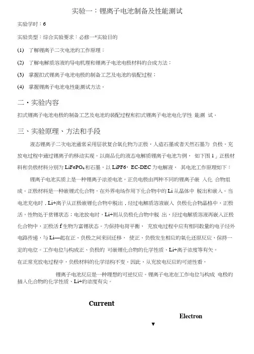
以商品化的液态电解质锂离子电池为例,如下图1」正极材料和负极材料分别为LiFePO4和石墨,以LiPF6・EC-DEC为电解液,其电池工作原理如下:锂离子电池实质上是一种锂离子浓差电池,正负电极由两种不同的锂离子嵌入化合物组成。
正极材料是一种嵌锂式化合物,在外界电场作用下化合物中的Li从晶体中脱出和嵌入。
当电池充电时,Li+离子从正极嵌锂化合物中脱出,经过电解质溶液嵌入负极化合物晶格中,正极活,性物处于贫锂状态;电池放电时,Li+则从负极化合物中脱出,经过电解质溶液再嵌入正极化合物中,正极活f生物为富锂状态。
为保持电荷平衡,充放电过程中应有相同数量的电子经外电路传递,与Li—起在正、负极之间来回迁移,使正、负极发生相应的氧化还原反应,保持一定的电位。
工作电位与构成正、负极的可嵌锂化合物的化学性质、Li+离子浓度等有矢。
在正常充放电过程中,负极材料的化学结构不变。
因此,从充放电反应的可逆性看,锂离子电池反应是一种理想的可逆反应。
锂离子电池在工作电位与构成电极的插入化合物的化学性质、Li+的浓度有尖。
CurrentElectron▼充电:L I F C PO A - xLi+・ M ・X F C PO A + (l-x)LiFePO4放电:F C PO A + xLi八 + M ・xLiFePO^ + (l-x)FePO4图1・1・锂离子电池工作原理> LiFePO4为正极‘石墨为负极.研究表明,Li+的脱嵌过程是一个两相反应,存在着LiFePCU和FePCU两相的转化,充电时,铁离子从FeOc层面间迁移出来,经过电解液进入负极,发生FJ+ TFJ+的氧化反应,为保持电荷平衡,电子从外电路到达负极。

实验5 锂离子电池装配及表征一.锂离子电池的工作原理锂离子电池是在以金属锂及其合金为负极的锂二次电池基础上发展来的。
在锂离子电池中, 正极是锂离子嵌入化合物, 负极是锂离子插入化合物。
在放电过程中, 锂离子从负极中脱插, 向正极中嵌入, 即锂离子从高浓度负极向低浓度正极的迁移;相反, 在充电过程中, 锂离子从正极中脱嵌, 向负极中插入。
这种插入式结构, 在充放电过程中没有金属锂产生, 避免了枝晶, 从而基本上解决了由金属锂带来的安全问题。
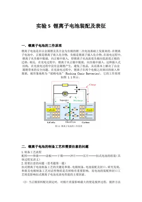
在充放电过程中, 锂离子在两个电极之间来回的嵌入和脱嵌, 被形象地称为“摇椅电池”(Rocking Chair Batteries), 它的工作原理如图 1.1所示。
二.锂离子电池的制备工艺和需要注意的问题1.制备工艺流程配料----和膏-----涂板----干燥-----冲片-----压片-----扣式电池的组装(具体过程见讲义)2.需要注意的问题(思考题第一题)扣式锂离子电池制备工艺的关键是和膏、电极制备、电池装配及封口。
研究发现, 和膏及电极制备工艺对活性物质是否掉粉有重要影响, 而电池的装配和封口工艺则是影响扣式锂离子电池充放电性能的主要因素。
(2)当正极原料配比固定时, 对极片质量影响最大的便是搅拌过程, 搅拌方法选择不好将会导致极片的导电性降低和极片掉粉, 极片掉粉将会直接影响电池容量等。
搅拌方式有超声波搅拌、磁力搅拌、强力搅拌以及手工研磨。
经研究发现采用强力搅拌和超声波搅拌得到的极片质量最好, 而在本实验中我们使用的搅拌效果最差的手工研磨, 这很难得到好的结果。
所以在和膏时要注意搅拌方式的选择。
(3)干燥温度和时间选择不适也会导致极片掉粉, 干燥的目的是为了除去膏体中大量的溶剂NMP 以及在配膏过程中吸收到的水分, 温度和时间都应选择合适。
压片时压力要选择适中, 压片的目的主要有两个: 一是为了消除毛刺, 使极片表面光滑、平整, 防止装配电池时毛刺穿透隔膜引起短路; 二是增强膏和集流体的强度, 减小欧姆电阻。
实验三锂离子电池的装配及其电化学性能测试一、实验目的1.了解扣式锂离子电池的装备过程;2.了解锂离子电池的工作原理。
二、实验原理1.锂离子电池的工作原理锂离子电池和所有的化学电源一样,主要是由正极、负极和电解质三部分组成,还包括电池壳、隔膜、正负极引线等。
锂离子电池对这些基础材料有一定的要求:正极材料要有高的开路电压,循环寿命长,比能量大;隔膜要求有一定的离子穿透性,允许锂离子通过,且有很好的耐氧化性和隔极阻止性等;负极材料也是要求比能量大,安全性好,能够进行快速的充放电;电解液要满足锂离子电导率高,电化学性能稳定,制备容易等。
锂离子电池实际上是锂的浓差电池,其原理为:在充放电过程中,Li+在正、负极的嵌入化合物中嵌入和脱嵌。
其正极材料为LiMO2(M为过渡金属),LiMn2O4或者钒的氧化物,负极材料一般用接近金属锂电池的C等可逆脱嵌锂材料,而电解液主要为无水有机溶剂。
充电时,Li+从正极脱嵌经过电解质嵌入负极,此时负极处于富锂态,正极处于贫锂态;放电时则相反,Li+从负极脱嵌,经过电解质嵌入正极,正极处于富锂态,负极处于贫锂态。
锂离子电池的工作电压与构成电极的锂离子嵌入化合物本身及锂离子的浓度有关。
因此,在充放电循环时,Li+分别在正负极上发生“嵌入-脱嵌”反应,Li+便在正负极之间来回移动,所以,人们又形象地把锂离子电池称为“摇椅电池”或“摇摆电池”。
锂离子电池表达式: (-)C n︱electrolyte︱LiM2O4(+)具体反应如下:正极反应:LiM2O4Li(1-x) M2O4 + xLi+ + xe-负极反应:nC+ xLi+ + xe- Li x C n电池反应:Li M2O4 + nC Li(1-x) M2O4 + Li x C n 2.电池的组装使用模拟纽扣电池能够方便的测试电极材料的比容量和循环性能。
其结构及装配顺序如图2.2所示。
首先将制成的正极片在120℃的真空干燥箱中干燥12h 后作为电池的正极,以锂片作为负极,聚丙烯微孔膜Celgard2032为隔膜,泡沫镍为集电器,1mol/L LiPF6的EC+DMC(体积比1:1)为电解液,在充满氩气(氧含量和水含量均小于1ppm)的真空手套操作箱中组装成LIR2025模拟纽扣电池。

《锂电资讯》增刊锂离子模拟电池组装测试手册编者王琦北京工业大学材料学院目录知识背景与内容简介................................ ......................................................... . (3)第1章模拟电池部件的介绍................................ .................................................. (4)1.1. 模拟电池的主要组件 (4)1.2. 部件的简单介绍 (4)1.2.1. 扣式电池壳 (4)1.2.2. 正极片 (5)1.2.3. 隔膜 (6)1.2.4. 负极片 (6)1.2.5. 集电器 (7)1.2.6. 支撑片 (7)1.2.7. 电解液 (8)1.3. 部件介绍的总结 (8)第2章模拟电池部件的制备................................ .................................................. (9)2.1. 制备正极片 (9)2.1.1. 油性体系中制备正极片 (9)2.1.2. 水性体系中制备正极片 (10)2.2. 裁剪电极片 (10)2.3. 正极材料含量的计算 (11)2.4. 裁剪隔膜 (11)第3章模拟电池的组装................................ ..................................................... (1212)3.1. 手套箱内组装电池 (12)3.2. 手套箱内压制电池 (13)第4章模拟电池的测试................................ ..................................................... (1414)4.1. 电池测试系统 (14)4.2. 电池测试的单位与参数 (14)4.2.1. 容量性能的单位与参数 (14)4.2.2. 循环性能的单位与参数 (15)4.2.3. 倍率性能的单位与参数 (15)4.3. 测试电池参数的设置 (15)知识背景与知识背景与内容内容内容简介简介随着石油资源的日益匮乏,能源危机日益临近。
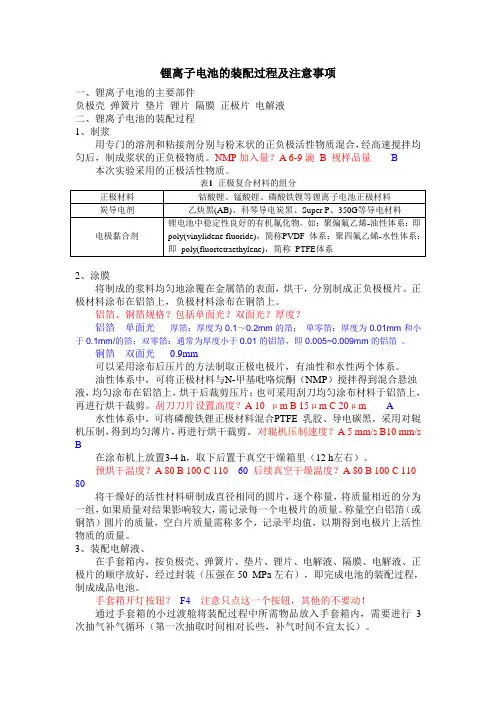
锂离子电池的装配过程及注意事项一、锂离子电池的主要部件负极壳弹簧片垫片锂片隔膜正极片电解液二、锂离子电池的装配过程1、制浆用专门的溶剂和粘接剂分别与粉末状的正负极活性物质混合,经高速搅拌均匀后,制成浆状的正负极物质。
NMP加入量?A 6-9滴 B 视样品量 B 本次实验采用的正极活性物质。
2、涂膜将制成的浆料均匀地涂覆在金属箔的表面,烘干,分别制成正负极极片。
正极材料涂布在铝箔上,负极材料涂布在铜箔上。
铝箔、铜箔规格?包括单面光?双面光?厚度?铝箔单面光厚箔:厚度为0.1~0.2mm的箔;单零箔:厚度为0.01mm和小于0.1mm/的箔;双零箔:通常为厚度小于0.01的铝箔,即0.005~0.009mm的铝箔。
铜箔双面光0.9mm可以采用涂布后压片的方法制取正极电极片,有油性和水性两个体系。
油性体系中,可将正极材料与N-甲基吡咯烷酮(NMP)搅拌得到混合悬浊液,均匀涂布在铝箔上,烘干后裁剪压片;也可采用刮刀均匀涂布材料于铝箔上,再进行烘干裁剪。
刮刀刀片设置高度?A 10 μm B 15μm C 20μm A 水性体系中,可将磷酸铁锂正极材料混合PTFE 乳胶、导电碳黑,采用对辊机压制,得到均匀薄片,再进行烘干裁剪。
对辊机压制速度?A 5 mm/s B10 mm/s B在涂布机上放置3-4 h,取下后置于真空干燥箱里(12 h左右)。
预烘干温度?A 80 B 100 C 110 60 后续真空干燥温度?A 80 B 100 C 110 80将干燥好的活性材料研制成直径相同的圆片,逐个称量,将质量相近的分为一组,如果质量对结果影响较大,需记录每一个电极片的质量。
称量空白铝箔(或铜箔)圆片的质量,空白片质量需称多个,记录平均值,以期得到电极片上活性物质的质量。
3、装配电解液、在手套箱内,按负极壳、弹簧片、垫片、锂片、电解液、隔膜、电解液、正极片的顺序放好,经过封装(压强在50 MPa左右),即完成电池的装配过程,制成成品电池。
终于找到了!史上最详细扣式电池极片制备和电池组装教程2018-11-13 V 微算云平台实验室锂离子扣式样品电池,包括半电池(half cell,正极极片/金属锂片、负极极片/金属锂片)、全电池(正极极片/负极极片)以及对称电池(正极极片/正极极片、负极极片/负极极片)。
扣式电池由成套的扣式电池壳及内部组件构成,不锈钢电池壳电化学稳定性好、密封性良好、尺寸较小、组装较为简单、价格便宜、适用温度为40~80℃,适合大量测试使用。
最近国内外企业开始研制高通量扣式电池自动组装设备,用于电池关键材料的批量加速验证和研发。
一般的扣式电池壳型号有CR2032、CR2025、CR2016等,实验室中常采用CR2032 型电池壳(即直径为20 mm,厚度为3.2 mm)。
扣式电池壳用后则报废,需增加金属回收环节以免浪费和污染环境。
还有一种可重复使用的电池——Swagelok电池,又称为模拟电池,也经常用于实验室测试,其电池壳采用不锈钢外壳和聚四氟乙烯内胆,可重复使用。
Swagelok型电池拆解便捷,适合用于电池拆解分析。
但模拟电池相对成本较高,且组装出一致性较好的电池需要规范的训练和一定经验。
一套CR2032 型电池壳包括:负极壳,弹片,两个垫片。
组装一个扣式电池的基本步骤包括:制浆、涂布、烘干、裁片、组装。
下面进行详细解释。
极片的制备实验室用极片制备过程可分为混料和涂覆两个步骤。
其中混料工艺主要包括手工研磨法和机械混浆法,涂覆工艺则包括手工涂覆和机械涂覆。
实验室进行混料时,依据供料的多少来确定采用手工研磨法或机械混浆法,如活性材料的质量在0.1~5.0 g时建议采用手工研磨法,活性材料的质量超过5.0 g时,建议采用实验室用混料机进行混料。
实验室中每次混浆量有限,常采用手工涂覆,当浆料足够时可采用小型涂覆机。
整个极片制作过程需要在干燥环境下进行,所用材料、设备都需要保持干燥。
图1为手工混料、手工涂覆方法制备极片过程,包括材料准备、活性材料和导电剂的称取和研磨、加入黏结剂、浆料研磨、取出浆料手工涂布极片、极片烘烤等步骤。

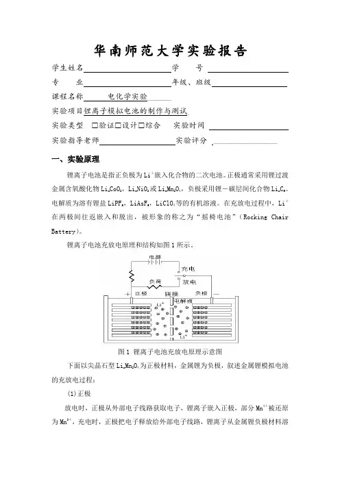
华南师范大学实验报告学生姓名学号专业年级、班级课程名称电化学实验____________实验项目锂离子模拟电池的制作与测试_实验类型✉验证✉设计✉综合实验时间实验指导老师实验评分 ________________________________一、实验原理锂离子电池是指正负极为Li+嵌入化合物的二次电池。
正极通常采用锂过渡金属含氧酸化物Lix CoO2,LixNiO2或LixMn2O4,负极采用锂-碳层间化合物LixC6。
电解质为溶有锂盐LiPF6,LiAsF6,LiClO4等的有机溶液。
在充放电过程中,Li+在两极间往返嵌入和脱出,被形象的称之为“摇椅电池”(Rocking Chair Battery)。
锂离子电池充放电原理和结构如图1所示。
图1 锂离子电池充放电原理示意图下面以尖晶石型Lix Mn2O4为正极材料,金属锂为负极,叙述金属锂模拟电池的充放电过程:(1)正极放电时,正极从外部电子线路获取电子,锂离子嵌入正极,部分Mn4+被还原为Mn3+,充电时,正极把电子释放给外部电子线路,锂离子从金属锂负极材料溶出,电极反应为:Lix Mn 2O 4 + yLi + + ye Li x+y Mn 2O 4(2)负极充放电时电极反应为:Li Li + + e锂离子在电解液中,通过微孔薄膜往返迁移,然后沉积到锂电极上。
电子在外部线路中转移而释放或消耗能量。
这种锂电池的充放电过程可以看到,锂离子的化合价态始终保持+1价,无价态转变,所以这种二次电池叫“锂离子电池”。
二、实验材料仪器1、实验材料:锰酸锂(Li x Mn 2O 4)、铜箔、隔膜、锂片、电解液(1M LiPF 6溶于体积比 EC: DEC:EMC=1:1:1的溶液)、扣式电池壳(CR2032)、电池垫片、电池弹片、纽扣电池座等。
2、实验仪器CorreTest CS350电化学工作站、电子分析天平、台式干燥箱、真空干燥箱等。
三、实验流程与步骤(一)实验流程A 搅拌→B 涂膜→烘烤→C 辊压极片→D 切片→E 切膜→F 封装→G 测试(二)实验流步骤1、正、负极的制备a 、正极的制备按8:1:1的质量比,分别称取1.6054 g 锰酸锂、0.2005g 乙炔黑和0.2001g 粘结剂聚偏二氟乙烯(PVDF ),混合均匀后,加入4 mL 溶剂N-甲基-2-吡咯烷酮(NMP ),在烧杯中充分搅拌20分钟左右并调节好物料的粘度,然后使用加热涂膜机在铝箔的绒面上(集流体)涂成均匀的薄膜,置于80℃烘箱中烘2小时,再在120℃烘箱中烘6~8小时至实干。
锂离⼦电池制作、表征和性能测试综合实验指导书锂离⼦电池制作、表征和性能测试综合实验⼀、实验⽬的1、掌握锂离⼦电池正负极电极⽚的制备技术。
2、了解纽扣式锂离⼦电池的装配技术。
3、了解并掌握纽扣式锂离⼦电池的测试表征技术(充放电测试、CV测试及交流阻抗测试等)并会处理分析测试数据。
4、了解锂离⼦电池正极和负极材料种类,掌握区别锂离⼦电池材料的⽅法(例如SEM、XRD、电池充放电特性等)。
5、掌握成品电池的测试⽅法,会分析成品电池的测试数据。
⼆、实验原理锂离⼦电池主要由正极、负极、电解液和隔膜等⼏个部分组成。
⽬前商⽤的锂离⼦电池正极材料主要是磷酸铁锂、钴酸锂、锰酸锂和三元材料;负极是碳材料组成,如MCMB,天然⽯墨等;隔膜采⽤具有微细孔的有机⾼分⼦隔膜,如美国Celgard隔膜;电解液由有机溶剂和导电盐组成,有机溶剂采⽤碳酸⼄烯酯、碳酸⼆甲酯等,导电盐采⽤LiClO4、LiPF6、LiAsF6、LiBF4等。
负极的集流体为铜箔,正极的集流体铝箔。
通常使⽤的粘结剂为聚偏氟⼄烯(PVDF)等。
使⽤粘结剂把⽯墨、钛酸锂等负极材料粘附在铜箔上做成薄膜作为负极。
由于正极材料导电性不好,故必须加⼊导电炭⿊材料。
按照⼀定的配⽐,把活性料、炭⿊和PVDF混合均匀,加⼊适量溶剂制成具有⼀定流动性的胶状混合物,在铝箔上均匀涂布,经真空⼲燥后即可作为正极。
正负极都必须采⽤可以使Li+嵌⼊/脱出的活性物质,其结构⽰意图如图1所⽰:图1 ⼆次锂离⼦电池结构⽰意图由于扣式锂离⼦电池(CLIB) 质量轻、体积⼩,更能满⾜现代社会⽤电设备的⼩型化和轻量化的要求,⽬前CLIB 已商品化,主要⽤作⼩型电⼦产品电源,如:电脑主板、MP3 ⼿表、计算器、礼品、钟表、玩具、蓝⽛⽿机、PDA、电⼦匙、IC 卡、⼿摇充电⼿电筒等产品中,寿命可达5~10 年。
另外, CLIB 较圆柱形和⽅形锂离⼦电池成本低,封⼝容易,设备要求简单,因此,近年来很多电池公司、⼤专院校和科研院所的研发部门对开发CLIB 越来越重视。
【超干货】锂离子电池测试手册一部分电池电性能测试内容说明:① 1C倍率:电池容量如果为5Ah,1C指电流为5A,2C指电流为10A。
② C5:指5小时率,相当于0.2C电流进行放电一、电池容量在温度23℃±2℃下,以1C电流恒流放电至截止电压,所放出的容量为电池的额定容量即常说的电池容量。
二、标称电压(额定电压)又称中值电压,表示电池常规输出电压的近似值。
三、充电恒流比电池在经过恒流充电、恒压充电至终止电压时,恒流充入的容量占总充入容量的比值,恒流比=恒流充入容量/(恒流充入容量+恒压充入容量)*100%。
四、倍率测试4.1 倍率充电测试1)电池以1C电流放电后,然后以1C电流充电,计算1C充入容量/出始容量*100%2)电池以1C电流放电后,然后以3C电流充电,计算3C充入容量/出始容量*100%3)电池以1C电流放电后,然后以5C电流充电,计算5C充入容量/出始容量*100%……4.2 倍率放电测试1)电池以1C电流充电后,然后以1C电流放电,计算1C放入容量/出始容量*100%2)电池以1C电流充电后,然后以3C电流放电,计算3C放入容量/出始容量*100%3)电池以1C电流充电后,然后以5C电流放电,计算5C放入容量/出始容量*100%……五、低温性能测试(高温性能测试)以1C电流恒流恒压充至终止电压,然后将电池放于低温-10℃、-20℃或-40℃适用30min~60min,再用1C电流放电至截止电压,计算低温放电率 = 1C放电容量/初始容量*100%。
六、容量保持测试一般指电池充满电后,常温或高温放置一段时间,然后以1C电流放电,计算容量保持率 = 1C放电容量/初始容量*100%七、容量恢复能力容量恢复又称荷电恢复能力,测试方法为电池充满电后,常温或高温放置一段时间,然后以1C电流放电,再进行1C电流充电,最后1C电流进行放电,计算容量恢复能力 = 最后放电容量/初始容量*100%八、循环测试电池以nC电流进行恒流恒压充电,然后以nC电流进行放电,循环X次,直到容量为初始容量的80%停止测试注:目前也有应用功率循环,更符合使用条件,电动工具普遍还是恒功充放电九、电压自放电测试(K值)将电池电压调整到某工艺值,置于设定温度下t时或天,连续测试电池电压变化K=(Vt-V0)/t其中:Vt为最后测试电压值V0为初始电压值t为时间二部分电池安全性能测试项目说明:① 1C倍率:电池容量如果为5Ah,1C指电流为5A,2C指电流为10A。
Specification Approval Sheet Name:Polymer Lithium-Ion BatteryModel: CELLEVIA BATTERIES LP433078SPEC:3.7V/ 1050mAhNumber: 433078Specification Modification RecordsContent1.Scope:This specification describes the Product Specification of chargeable Polymer Lithium-IonBattery produced by Cellevia.Any copies are invalid without our company’s approval2.Model :3.Cell parameters Index:3.2 Parameters of batterythe temperature.4.Electronic Characteristics test and inspection:4.1 Standard testing environmentUnless special stated, tests should be done within one month of delivery and thecharging-recharging times is less than 5 times. The following is test conditions: Ambient Temperature: 25℃±0.5℃Ambient Humidity: 65 ±20%4.2 The requirement of measure instrument(1) The measure instrument is passed tested by qualified institute.(2) The accuracy of the size instrument is not more than 0.01mm.(3) The accuracy of multimeter is not less than 0.5%. while measure the voltage, theinternal resistance mustn’t less than 10KΩ.(4) The principal of the internal resistance is 1KHz LCR, the accuracy is 0.2%.(5) The internal resistance is changeable, it varies according to the temperature and thecharging mode. And it is relevant to the PTC and the length and the Capacity of the drawing line.(6) The current accuracy of the battery test system is more than ±0.1%,isobaricallyaccuracy is ±0.5%, timer accuracy is less than ±0.1%.(7) The accuracy of the temperature meter is less than ±0.5℃.4.3 Visual inspectionAny visual inspection defects will affect the electronic characteristics, such as cracks,leakage, and flaw, are not inexistence.Notes: The Max. voltage while charging is not more than 4.25V.The Max.protective voltage designed on PCB board should not more than4.3V.5. Storage and others5.1 Long Period StorageIf the cell has been stored for 3 month, it should be transfer to a dry and cool environment. Storage Voltage is between 3.6V and 3.9V and the storage conditions as Item 4.1.5.2Any matters that this specification does not cover should be conferred between theSpecification Approval sheet6.Drawing6.1 Assembly diagram(not in scale)Model :LP4330783078105031.0MAX30adhesive wire black AWG2660wire red (+)AWG265070m A hE V I A B A T T E R I E S 3,7 V! Danger●Strictly prohibits heat or throw cell into fire.●Strictly prohibits throw and wet cell in liquid such as water, gasoline or drink etc.●Strictly prohibits use leave cell close to fire or inside of a car where temperature may be above60°C. Also do not charge / discharge in such conditions.●Strictly prohibits put batteries in your pockets or a bag together with metal objects such asnecklaces. Hairpins,coins, or screws. Do not store or transportation batteries with such objects.●Strictly prohibits short circuit the (+) and (-) terminals with other metals.●Do not place Cell in a device with the (+) and (-) in the wrong way around.●Strictly prohibits pierce Cell with a sharp object such as a needle.●Strictly prohibits disassemble or modify the cell.●Strictly prohibits welding a cell directly.●Do not use a Cell with serious scar or deformation.●Thoroughly read the user’s manual before use, inaccurate handling of lithium ion rechargeablecell may cause leakage, heat, smoke, an explosion, or fire, capacity decreasing.! Warning●Strictly prohibits put cell into a microwave oven, dryer, or high-pressure container.●Strictly prohibits use cell with dry cells and other primary batteries, or new and old battery orbatteries of a different package, type, or brand.●Stop charging the Cell if charging is not completed within the specified time.●Stop using the Cell if abnormal heat, odor, discoloration, deformation or abnormal condition isdetected during use, charge, or storage.●Keep away from fire immediately when leakage or foul odor is detected.●If liquid leaks onto your skin or clothes, wash well with fresh water immediately.●If liquid leaking from the Cell gets into your eyes, do not rub your eyes. Wash them well with cleanedible oil and go to see a doctor immediately.! Caution●Before using the Cell, be sure to read the user’s manual and cautions on handling thoroughly.●Charging with specific charger according to product specification. Charge with CC/CV method.Strictly prohibits revered charging. Connect cell reverse will not charge the cel. At the sametime, it will reduce the charge-discharge characteristics and safety characteristics, this will leadto product heat and leakage.●Store batteries out of reach of children so that they are not accidentally swallowed.●If younger children use the Cell, their guardians should explain the proper handling.●Before using the Cell, be sure to read the user’s manual and cautions on handling thoroughly.●Batteries have life cycles. If the time that the Cell powers equipment becomes much shorter thanusual, the Cell life is at an end. Replace the Cell with a new same one.●When not using Cell for an extended period, remove it from the equipment and store in aplace with low humidity and low temperature.●While the Cell pack is charged, used and stored, keep it away from objects or materials with staticelectric charges.●If the terminals of the Cell become dirty, wipe with a dry clothe before using the Cell.●Storage the cells in storage temperature range as the specifications, After full discharged, wesuggest that charging to 3.9~4.0V with no using for a long time.●Do not exceed these ranges of the following temperature ranges.Charge temperature range : 0 °C to 45 °C;Discharge temperature range : -20 °C to 60 °C.(When using equipment)Handling Precaution and GuidelineFor LIP (Lithium-Ion Polymer) Rechargeable BatteriesPrefaceThis document of ‘Handling Precautions and Guideline LIP Rechargeable Batteries’shall be applied to the battery cells manufactured by CELLEVIA.Note (1): The customer is requested to contact CELLEVIA in advance, if and when the customer needs other applications of operating conditions than those described in this document. Additional experimentation may be required to verify performance and safety under such condition.Note (2): CELLEVIA will take no responsibility for any accident when the cell is used under other condition.Note (3): CELLEVIA will inform, in a written form, the customer of improvement(s) regarding proper use and handling of the cell, if it is deemed necessary.1. Charging 1.1ChargingCurrent:Charging current should be less than maximum charge current specified in theSpecification Approval Sheet.1.2 Charging Voltage:Charging voltage should be less than the maximum nominal voltage 4.2V, andthe charging voltage upper limited is 4.30V(single pack).1.3 Charging Temperature:The cell should be charged within the range specified in this Specification ApprovalSheet.1.4 Notes:Since charging with constant current or constant voltage, reverse charging isprohibited. In case of the cell is connected improperly, the cell cannot be charged.Simultaneously, the reverse charging may cause damaging to the cell whichmay lead to degradation of cell performance and damage the cell safety, andcould cause heat generation or leakage.2. Discharging Current:The cell shall be discharged at less than the maximum discharge current specified in the Specification Approval Sheet. High discharging current may reduce the discharging capacity significantly or cause over-heat.3. Discharging TemperatureDischarging Temperature should be within the range specified in this Specification Approval Sheet.4.Over-DischargeOver-discharging will cause cell low-performance and function loss. The cell would be in a over-discharged state by its self-discharge characteristic. In order to prevent over-discharging, the cell shall be charged periodically to maintain between 3.6V and 3.9V.5. Protective Circuit Module5.1 The cell / battery pack shall be with a PCM that can protect cell / battery packproperly. PCM shall have functions of(1) Overcharging prevention(2) Over-discharging prevention(3) Over current prevention to maintain safety and prevent significant deteriorationof cell performance. The over current can occur by external short circuit.5.2 Overcharging ProtectionOvercharging prevention function shall stop charging if any cell of the battery packreaches 4.30V.5.3 Over-discharging protectionOver-discharging protection function shall monitor the voltage of every cell in the pack, and work to avoid further drop in the cell voltage of 2.75V or less.6. StorageCells should be stored in proper temperature specified in Specification ApprovalSheet.7. AppearanceIt shall be free from any defects such as remarkable scratches, breaks, cracks,discoloration, leakage or deformation .8. Notice△!8.1 Handling of cells:Avoid any short-circuit, it will caused the pole hot and lost electronic functions.Soft packing is very damaged by sharp edge parts such as needles and knives.Avoid cells touch with sharp edge part, when handling and storage.Beside the poles is the sealed edge. Don’t bend or fold dealing edge, for it is a sensitive part.Don’t open the folding edge on both sides of the cells.Don’t bend the tabs, for the tabs are not so stubborn.Avoid mechanical shock to the cells.Don’t put the cells into the heater, washing machine or high-voltage container.Don’t use the charger without any safety guarantee, and recommend you use specified charger.You should immediately stop charging, as cell is overheating, delivery any smell, changed color, distortion etc.Before Children use batteries, adults should explain the usage first.Before use batteries, please read the handling guideline carefully and fully understand.Away from the static-electronic field, while using, charging and storing cells.Don’t put the cells together with metal conductors such as chains, barrette, bolt into the pocket or stored them together.Don’t use metal conductor to shortcut the positive and negative poles.Don’t mis-assemble the positive pole with the negative one.8.2 Notice for Designing Battery Pack8.2.1 Package DesignBattery pack should have sufficient strength and battery should be protected from mechanical shock.No sharp edge components should be inside the pack containing the battery.The overcharge threshold voltage should not be exceed 4.30V (single pack)The over-discharge threshold voltage should not be lower than 2.9V (single pack)The PCM should have short protection built inside.8.3 Notice for Assembling Battery Pack8.3.2 Tab connectionUltrasonic welding or spot welding is recommended to connect battery with PCM or other parts.If apply manual solder method to connect tab with PCM, below notice is very important to ensure battery performance.8.3.2.1 The solder iron should be temperature controlled and ESDsafe.8.3.2.2 Soldering temperature should not exceed 350℃.8.3.2.3 Soldering time should not be longer than 3 seconds .8.3.2.4 Keep battery tab cold down before next time soldering.8.3.2.5 Directly heat cell body is strictly prohibited. Battery shouldbe damaged by heat above approx. 60℃.8.3.3 Cell fixingThe battery should be fixed to the battery pack by its large surface area.No sharp edge at the assembling position.No cell movement in the battery pack should be allowed.9.Others9.1 The disassembling may generate internal shout circuit in the cell, which may causegassing, firing, or other problem.9.2 Prohibition of dumping of cells into fireNever incinerate or dispose the cells in fire, for these may cause firing of the cells.9.3 The cells should never be soaked with liquids such as water, drinks or oil.9.4 Prohibit using the cells mixed with different manufactories. Prohibit using new cellsmixed with old ones.▲Special Notice: If the cell isn’t used for a long time, Please Keep the cells in half-charged state, which is keeping them unfully charged or incompletely discharged. Recharge the cells and use half of the power after 2-3months. Store the cells in cool and dry place. It will protect the cell from damage effectively and long-term.10. StatementIf our specifications material, product process or product control system has changed, the information will be transmitted to consumer by way of written with quality and reliability data.。
实验三锂离子模拟电池的制作与测试1.【实验目的】4. 熟悉、掌握锂离子电池的结构及充放电原理;5. 熟悉、掌握锂离子正极材料的制备过程及工艺;136. 熟悉、掌握锂离子电池的封装工艺及模拟电池测试方法。
2.【实验原理】锂离子电池是指正负极为Li+嵌入化合物的二次电池。
正极通常采用锂过渡金属氧化物Li x CoO2,Li x NiO2 或Li x Mn2O4,负极采用锂-碳层间化合物Li x C6。
电解质为溶有锂盐LiPF6,LiAsF6,LiClO4 等的有机溶液。
溶剂主要有碳酸乙烯酯(EC)、碳酸丙烯酯(PC)、碳酸二甲酯(DMC)和氯碳酸酯(CIMC)等。
在充放电过程中,Li+在两极间往返嵌入和脱出,被形象的称之为“摇椅电池”(Rocking Chair Battery)。
锂离子电池充放电原理和结构示意图如下图:锂离子电池的化学表达式为:(-)Cn| LiPF 6- EC + DMC |LiMxOy(+)其电池反应为:LiM x O y+ nC←−−−→Li1-x MxO y + Li x C n下面以尖晶石型Li x Mn2O4 为正极材料,富锂层状石墨为负极,叙述锂离子的充放电过程:(1)正极放电时,正极从外部电子线路获取电子,锂离子嵌入正极,部分Mn4+被还原为Mn3+,充电时,正极把电子释放给外部电子线路,锂离子从正极材料中脱嵌,电极反应为:14x 2 4 x y 2 4 Li Mn O yLi ye Li Mn O ++ + + ←−−−−−−→放电充电(2)负极放电时,负极石墨层间的锂离子脱出,同时电子通过外部电子线路释放,充电时,从外部电子线路获取电子,锂离子嵌入,电极反应为:z z y Li C Li C yLi ye +- ←−−−−−−→ + +放电充电锂离子在电解液中,通过微孔薄膜往返迁移,然后嵌入到电极中。
电子在外部线路中转移而释放或消耗能量。
从锂离子电池的充放电过程可以看到,锂的化合价态始终保持+1 价,无价态转变,所以这种二次电池叫“锂离子电池”。