C5116E使用说明书
- 格式:doc
- 大小:2.65 MB
- 文档页数:12
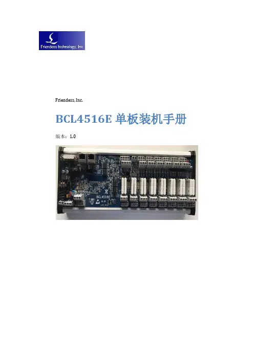
Friendess, Inc.BCL4516E单板装机手册版本:1.0文档修订记录目录文档修订记录 (1)目录 (2)1 产品介绍 (3)1.1 产品简介 (3)1.2 硬件资源 (3)2 接线说明 (4)2.1 安装尺寸 (4)2.2 接口说明 (5)2.2.1 接口布局 (5)2.2.2 电源接口说明 (5)2.2.3 伺服驱动器接口说明和参数设置 (6)2.2.4 专用输入接口说明 (8)2.2.5 通用输入接口说明 (9)2.2.6 通用输出接口说明 (9)2.2.7 模拟量输出信号接口说明 (10)2.2.8 PWM输出信号接口说明 (10)2.3 接线图 (11)1产品介绍1.1产品简介BCL4516E是一款基于EtherCAT总线的IO扩展板,支持FSCUT5000B总线数控系统所需的外设资源。
1.2硬件资源硬件资源说明表2接线说明2.1安装尺寸BCL4516E的尺寸图如下图所示:2.2 接口说明2.2.1 接口布局BCL4516E 接线端子详细接口布局如下图所示:2.2.2 电源接口说明24V 0V 24V 24V 24V两芯端子为电源输入端,接24V DC 电源模块;三芯端子为电源输出端,用于给传感器供电。
2.2.3伺服驱动器接口说明和参数设置BCL4516E上的伺服控制接口为DB15双排孔,对应线材的引脚定义如下图所示:与之配套使用的伺服电缆线的信号线定义如下表所示:24V、0V:为伺服驱动器供DC 24V电源;SON:使能,输出伺服驱动使能信号;ALM:报警,接收伺服驱动器报警信号;PUL+、PUL-:脉冲,差分输出信号;DIR+、DIR-:方向,差分输出信号;A+、A-、B+、B-、Z+、Z-:编码器三相,输入信号。
其中SON和ALM信号只支持低电平有效。
与安川伺服驱动器的接线请参看下图。
安川伺服接线图上海柏楚DB15伺服控制接口安川Σ-V伺服50P接口连接其它品牌驱动器时注意以下事项:(1)请首先确定您选择的伺服驱动器SON 信号的类型,是否是低电平有效(即与24V电源的GND 导通时为ON);(2)确定伺服驱动器的参数设定为:接收的脉冲信号类型是“脉冲+方向”;(3)确定伺服驱动器输入端子中有无外部紧停信号输入,以及该信号的逻辑;(4)驱动器试运转前,必须先给端子板供24V 电源,因为伺服器所需24V 电源是通过端子板转供的;(5)如果驱动器还不能运转,确定驱动器参数设定为不使用“正反转输入禁止”。
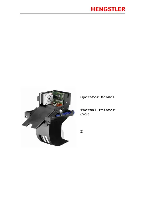
Operator Manual Thermal Printer C-56EReleaseChanges© 2005 - 2018 by HENGSTLERThis document is protected by copyright by HENGSTLER GmbH.This document may not be changed, altered, duplicated or reproduced in any manner, or provided or transmitted to any third persons or organizations, without the prior written approval of HENGSTLER.We reserve the right to make technical changes, modifications or improvements without prior notice.Hengstler and the Hengstler logo are registered trademarks of Hengstler GmbH. Other brand and product names used herein are trademarks or registered trademarks of their respective companies. HENGSTLER GmbHUhlandstr. 4978554 Aldingen / GermanyTel. +49 (0) 7424-89 0Fax +49 (0) 7424-89 500eMail:******************ContentsR ELEASE (2)C HANGES (2)1.0Introduction (4)1.1A DDITIONAL L ITERATURE (4)2.0Important Information and Safety Instructions (5)2.1G ENERAL I NFORMATION (5)2.2S YSTEM-S PECIFIC S AFETY I NSTRUCTIONS AND S YMBOLS (5)2.3P RINTER I NSTALLATION (6)3.0Layout and Function (7)3.1S TRUCTURE OF THE C-56T HERMAL P RINTER (7)3.2F UNCTIONS OF THE P RINTER (8)4.0Operation (10)4.1S TART UP OF THE S YSTEM (10)4.2L OADING OF P APER (10)5.0Troubleshooting (11)5.1C LEARING P APER J AMS (12)5.2R EPLACEMENT OF C OMPONENTS (13)6.0Technical Data (14)6.1G ENERAL D ATA (14)6.2C ONFIGURATION OF THE I NTERFACES (15)6.3P APER S PECIFICATIONS (16)6.4D ATA SPECIFIC TO P RINTING (16)6.5O RDER N UMBERS FOR S PARE M ODULES: (16)1.0IntroductionThank you for selecting the Hengstler C-56 printer! We are proud of this feature-rich product, which was designed using all our expertise and experience, and we are confident that you will be pleased with the advanced features and outstanding performance.This Operator Manual is designed to help you with the proper installation, connection to your host computer system and start-up of the C-56 thermal printer system. All necessary details will be further explained in the following sections. Please read this manual carefully before starting up the thermal printer. If you have any further questions, please do not hesitate to contact our head office or one of our branch offices.The thermal printer does not require any servicing and is intended primarily for printing documents and receipts, at a printing speed up to 220 mm/sec for the 24 VDC version, and up to 160 mm/sec for the 12 VDC version, when powered by an appropriate power supply and when printing on endless thermal paper with paper weight ranging from 50 to 60 g/m2. The paper width may vary from 58 to 60 mm (2.28" to 2.36"). While documents may be any length greater than 120 mm, most documents will fall in the range of 120 to 297 mm.The horizontal and vertical print density is 203 dpi so that graphics, such as logos etc. can be printed with good quality.The printer mechanism has been designed in particular for application in self-service gasoline pumps in service stations, in terminals and vending applications. The modular design enables the main components to be replaced in less than 2 minutes. The controller integrated in the printer mechanism controls all printing functions and is provided with an USB 1.1 port for the host computer. Driver software is available that supports the Windows XP/7/8/10 and Linux operating systems. In addition, the printer can also be activated directly in ASCII mode through ESC/FS sequences; a detailed description of the different sequences is contained in the Emulation Manual.1.1 Additional LiteratureC-56 Emulation Manual D 684 017Paper Specification (English) Paper Specification (German) D 684 012 D 684 010Dimensional Drawing D 684 048 etc; see the C-56 download area at www.hengstler.de2.0 Important Information and Safety Instructions2.1 General InformationThe company Hengstler GmbH will not accept any liability for direct or consequential damages arising due to improper use of the thermal printer and, in particular, due to non-compliance with this operating manual or to improper handling and maintenance. The supply of technical documentation does not imply any authorization by Hengstler GmbH to make additions, repairs or modifications.This documentation may not be copied, nor shall its contents be disclosed or used commercially unless this has otherwise been explicitly agreed. The user is responsible for proper handling and installation of the printer. The printer should only be shipped in its original packing.2.2 System-Specific Safety Instructions and SymbolsHengstler GmbH will not accept any liability for the safe operation of the C-56 thermal printer unless Hengstler original products are used exclusively and the following instructions and recommendations are heeded.General warning for cases where the user or service personnel may be in danger.General notes and hints for operating the system safely.2.3 Printer InstallationThe C-56 printer uses electrically conductive housing materials which help to eliminate electrostatic charging during printing. In order to protect the printer from damages caused by externally applied charges, e.g. when electrostatically charged customers grab the receipt at the printer chute, the printer must be grounded. The mou nting holes of the printer’s base unit can be utilized for this where a ground wire with lug may be inserted in one of the two screw points.If the printer is mounted in an electrically conductive and already grounded panel, additional wiring can be omitted if sufficient electrical contact is ensured through the mounting points.3.0 Layout and FunctionAll modules of the C-56 thermal printer mechanism are delivered in operating condition. After connecting the printer to a USB 1.1 or 2.0 port on the host system (PC) and to a properly rated 24 VDC or 12 VDC power supply3.1 Structure of the C-56 Thermal PrinterFig.1Thermal printer, front view left handThe C-56 Thermal Printer is composed of three main units: thermal printer with integrated Controller, basic unit with paper tray and two hinge pins, and an eject chute supported by the basic unit. These hinge pins secure the printer mechanism on the basic unit. If both hinge pins are retracted in part, the printer mechanism can be re -moved. If only one hinge pin is retracted, the printer mechanism can be pivoted around the remaining hinge pin. The Eject Chute is provided with guides that engage in the basic unit firmly and with high dimensional accuracy. The paper roll lies in the paper tray loosely. The sensitive side of the thermal paper must be outside or beUSB or RS232 Interface,DC power connector on controller boardThermal printer mechanismHinge pinThermal paper rollMounting holesEject chute Base unit with paper trayOptional Paper Pre-End Sensor connectionPrinthead up lever3.2 Functions of the PrinterThe printhead of the C-56 printer mechanism has a horizontal resolution of 203 dpi (dots per inch). Thus, the 448 dots allow printing of lines with a maximum width of 56 mm. The stepper motor affects the paper feed by means of a platen that is rotated via gearing. The transmission ratio of this gearing has been selected in such a way that the vertical dot resolution is also 203 dpi; this corresponds to a paper movement of 0.125 mm. All functions of the printer mechanism are controlled by the integrated Controller.Fig. 2 Diagram of paper transportThe paper is inserted into the printer through the upper and lower paper guides and led over the platen. As soon as the reflective LED sensor L1a in the upper guide detects the front paper edge, 'automatic paper insertion' will start and the paper is transported until its front edge can be seized in the eject chute. The LED L2 signals thatAs an alternative, the reflective LED sensor L1b may be installed instead of the sensor L1a. It will detect the paper edges and recognize position identification marks (Black Marks) on the back side of the paper. The ejected paper is cut when the user pulls it from the printer, thereby tearing it straight over the cutter. The shape of the triangle cutter knife provides for a clean cut. The further paper transport will be carried out by program control.Optional reflective LED sensor L3 detects the presence of paper in the eject chute. The status of L3 can determined via the Query command and is reported as part of the C-56 status bytes. See the C-56 Emulation Manual D 684 017 for details on querying this sensor and the format of the response.Optional reflective LED sensor L4 is located on the left outside of the paper reservoir and detects when the diameter of the paper roll decreases below a fixed dimension, indicating that paper is low. This is a hardware alternative to the default paper low system, which requires thermal paper with black marks at the end of the paper roll. The status of L4 can determined via the Query command and is reported as part of the C-56 status bytes. See the C-56 Emulation Manual D 684 017 for details on querying this sensor and the format of the response.Fig. 2a C-56 with Hardware Paper Low Sensor4.0 OperationOnce the C-56 thermal printer is connected to the power supply and the host's interface port, and the driver (if needed) is installed, the printer is ready for use.4.1 Start up of the SystemFig. 3 Connections of the thermal printer to the system1. The connection to power supply is to be doneexclusively by means of the supplied cable. Make sure that the power supply is alwaysswitched off before the connector is plugged in or removed. The locking tab of the connector should always be directed towards the paper insert side.2. Connect the a) mini - USB port of the printermechanism with a USB – interface, or b) micro - RS232 port with a RS232 interface of your PC, using the supplied USB / RS232 cable. On USB, Windows will then automaticallyrecognize the new connected device and install the appropriate driver software.3. Install the driver software on the host system (PC).Please, consider the coordination of the drivers with the operating systems and respect the current instructions supplied together with the drivers.4.2 Loading of PaperFig. 4 Loading of the paper roll1. Pull the protective sheathing from the paper rolland cut the paper end at right angles to the direction of feed as far as possible. Truncated, lacerated or folded paper edges can produce a paper jam during automatic insertion. Also perforations of the paper web or rounded edgesare not acceptable.2. Lay the paper roll into the paper tray as shown inthe illustration. The thermal sensitive paper surface must be situated outside or on top.3. Insert the paper into the printer mechanism. Assoon as the sensor in the paper guide detects paper, the controller starts the automatic paper insertion.4. Cut off the paper appearing in the eject chute bypulling it straight out.Mini - USBLocking tab Connector Power SupplyMicro – RS232Be sure to use the supplied cable tie to secure the RS-232 cable and avoid possible damage to this connector.5.0 TroubleshootingThe paper path in the printer mechanism is almost straight so that proper paper feed and guiding will prevent paper jams (see also Fig. 2). The following malfunctions if any will be recognized and signaled by the integrated controller:5.1 Clearing Paper JamsIn order to clear a paper jam, detach the document that is already present in the eject chute and retract the remaining paper manually. Paper scraps remaining in the area between the print mechanism and eject chute can be removed after the printer is tilted open.Fig. 5 Open paper path for removing paper In case there is still paper between the printhead and the platen, remove the friction between head and platen by pressing down the lever and then pull the paper back by hand.Never actuate this lever during the printingoperation or else the printhead will overheat.Fig. 6 Tilt the printer mechanism open for paper removal If a partly printed document remains in the printer mechanism, e.g. in the event of a paper end signal due to a tear, and it does not appear in the eject chute, the printer mechanism will have to be tilted open and the document be taken out by hand. Note that additional care must be taken concerning wire routing if the optional chute sensor or hardware paper-low sensor are installed.1.2.3.4.Push to lift printheadDrivepinionPartlyprintedpaperLED L2Hinge pin5.2 Replacement of ComponentsThe C-56 thermal printer does not require any servicing. It has been designed such that its main modules represented in the illustration below can be replaced also by the operational staff after short briefing, within less than 2 minutes. The modules do not require any adjustment. Note that additional care must be taken concerning wire routing if the optional chute sensor or hardware paper-low sensor are installed.Fig. 7 Modular structure of the C-56 thermal printer with 4 main componentsThe eject chute is pushed into the guiding supports on the basic unit and cannot be removed when the printer mechanism is installed. It represents the only access to the printer for the customer. The hinge pins are inserted into the collars onto the basic unit in the sense illustrated above and then are pushed against the tilt position. Only in this position, the printer mechanism can be placed onto the basic unit, and when the hinge pins are snapped into the operating position, the printer will be locked on the basic unit. The two holes on the front of the basic unit serve for installing the C-56 thermal printer in vending applications etc.6.0 Technical Data 6.1 General DataEMC: EN55022 - EmissionWarning! The C-56 thermal printer is a class "A" appliance.It can produce radio interference in residential areas so that the user may be forcedto take adequate remedial measures.EN55024 - EMS ImmunityElectrostatic discharges and burst effects may cause short printing interruptions.But the automatic recovery function will restore the original state of the thermalprinting mechanism.Additional action regarding lightning and overvoltage protection will be needed, ifcables and wires are installed outside of a building.However, this standard can be met only if original units, components, and cablesare applied and the installation instructions are respected.When operating the printer from a DC building power supply, or when the DCpower cable exceeds 3 meters in length, appropriate EMI filters must be used.External interference caused by ESD or EMI can temporarily cause corruptedprinting or data loss.6.2 Configuration of the InterfacesNote: +5V is only connected in special versions6.3 Paper SpecificationsRecommended Paper Quality: Thermal papers 50 to 60 g/m2;thermosensitive surface on outside; see Paper Specification D 684 012Converting: Paper roll Roll width: 58 to 60 mm (2.28" to 2.36")Roll diameter: up to 100 mm (4")Typical: 75 mm (3") or 100 mm (4")The paper pre-end mark is to be printed on the coated paper side. For further dataregarding the printing of pre-end marks or 'Black Marks' please refer to the PaperSpecifications D 684 012.6.4 Data specific to Printing6.5 Order Numbers for Spare ModulesThermal Printer mechanism RS232 E2684001 Thermal Printer mechanism USB E2684002 Paper tray (contains 10 pieces) E2684009 Eject chute standard (contains 10 pieces) E2684005 Eject chute short (contains 10 pieces) E1684019 Hinge pin (contains 10 pieces) E2684012 DC power supply cable E1684009 USB Data Cable 0684102 RS232 Data Cable 0684103。
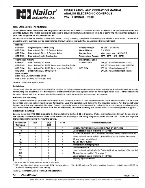
INSTALLATION AND OPERATION MANUALANALOG ELECTRONIC CONTROLSVAV TERMINAL UNITSCTE-5100 Series Thermostats:The CTE-5100 series thermostats are designed to be used with the CSP-5002 controller actuator. CTE-5100’s are provided with limited and unlimited outputs. The limited output(s) is (are) used to provided minimum and maximum limits to a CSP-5002. The unlimited output(s) is (are) used to operate fan and heat sequences.Models are available for cooling, cooling with reheat, cooling / heating changeover and day/night or set-back applications. Temperature averaging and/or overrides may be accomplished. Consult Nailor control submittal for applicable thermostat model.Models:CTE-5101Single setpoint; Direct Acting Supply Voltage:16 Vdc (14 - 20 Vdc)CTE-5103Dual setpoint; Direct & Reverse Acting Output Range:0 to 10VdcCTE-5104Dual setpoint; Direct & Reverse Acting Connections:Wire clamp type: 14-22 AWGCTE-5105Dual setpoint; both Direct Acting Temperature Range:55O F - 85O F (13O C - 29O C)Thermostat Action:Proportional Band:CTE-5101Direct Acting (DA) T1/T3CTE-5101/3/52O F, (1.1O C) w/limits output (T1/T2)CTE-5103Direct Acting (DA) T1/T3, Reverse Acting (RA) T2/T44O F, (2.2O C) w/o limits output (T3/T4) CTE-5104Direct Acting (DA) T1/T3, Reverse Acting (RA) T2CTE-51042O F, (1.1O C) w/limits output (T1)CTE-5105Direct Acting (DA) T1/T2/T3/T42O F, (1.1O C) w/limits output (T2/T3)Base Material:Black ABS, UL Flame Class 94HBSize2 9/16" (65 mm) x 3 7/16" (87 mm)Table 1.Thermostat Specifications.Installation:Thermostats must be mounted horizontally,(or vertically by using an optional vertical scale plate), utilizing the HMO-5030/5031 backplates for mounting to a standard 2" x 4" electrical box, or the optional HMO-5023 drywall bracket for mounting to hollow walls. Thermostats should be mounted on a wall in an area not affected by sunlight or drafts, to sense the average room temperature.Electrical box mounting:Install the HMO-5030/5031 backplate to the electrical box using the two 6-32 screws, supplied with backplate – do not tighten. The backplate is provided with one slotted mounting hole for leveling. Level the backplate and tighten the two mounting screws. Pull thermostat wires through backplate and decorative trim plate. Connect thermostat wires to the thermostat according to the wiring diagram supplied with the unit. Position the trim between the back plate and the thermostat, secure the assembly with the two 6-32 x 2" self tapping screws supplied. Hollow wall mounting:Loosely mount the HMO-5023 bracket to the thermostat using the two 6-32 x 2" screws. Pull all thermostat wiring through the opening on the bracket. Connect thermostat wires to the thermostat according to the wiring diagram supplied with the unit. Center and align the thermostat while tightening the mounting screws.Thermostat510151035104Terminals DescriptionTerminals5105V1X X X Velocity input for readout, connect to “out” on CSP-5002T3X X X Upper setpoint output w/o limits (0 -10 Vdc)R1X X X T1 override, connect to "-" if unused. Voltage applied subtracts from T1 T1X X X Upper setpoint output w/limits. Adjustable at pot.on front of thermostat +X X X16 Vdc power supply input12V X X X12 Vdc power outputA X X X Temperature averaging input-X X X Ground referenceT2X X Lower setpoint, output w/limits. * Adjustable at pot. on front of thermostat R2X X T2 override connect to "-" if unused **T4X Lower setpoint output w/o limits (0 -10 Vdc)V2X Velocity input for readout* Except 5104; T2 lower setpoint output is w/o limits.** R2 is auxiliary limit trigger on model 5104. Voltage above 1 Vdc @ R2 indexes T1 to the auxiliary flow limit. Install jumper R2-T2 for automatic indexing of aux. flow setting.Table 2.Thermostat Wiring Terminals and Description.Figure 1. Thermostat Detail Maintenance:No routine maintenance is required. Each component’s design and material selection assures dependable long-term reliability and performance. Careful installation will also enhance long term reliability and performance.CSP-5002 DAMPER CONTROLLER/ACTUATORAll Nailor standard right hand (and optional left hand) terminal units have a 1/2" (13), diameter drive shaft and a clockwise to close damper rotation (Dual Duct Left Hand Deck CCW to close). Full damper shaft rotation is 45 or 90 degrees depending on model. The CSP-5002should be mounted on the damper drive shaft so the actuator will stall at either end of the stroke to ensure tight shut-offs and full rotation.Ensure the two jumpers are set for the correct damper rotation.The CSP-5002 has a tri-color LED that indicates the current action of the damper: RED – Closing, GREEN – Opening, WHITE – Satisfied.The CSP-5002 provides pressure independent VAV control for terminal unit primary valves. Primary air volume is monitored by the use of a multi-point flow sensor located in the inlet duct. Differential pressure is measured by an onboard platinum transducer. The changes in the inlet static pressure will vary the position of the inlet damper. Flow limit adjustments are made using a digital DC voltmeter at the thermostat.The CSP-5002 is factory calibrated with VNOM adjustment centered for the enclosed voltage - airflow charts. Do not adjust. Dampers are always shipped in the full open position.(WHERE APPLICABLE)ACESS DOOR GEAR DISENGAGEMENT BUTTONP PORTS 3/16" (5) DIA. (2)Figure 2. CSP-5002 Controller / ActuatorPOWER REQUIREMENTS:Controller / actuator / thermostat is 7VA plus any output loads for fan relays, heating contactors and control valves (assume 10 VA each).Always switch control voltage off prior to disconnecting any wires from the controller.ANALOG CONTROL CALIBRATION CHARTS VOLTAGE VS. AIRFLOWWhen field adjustment or field calibration of the CTE-5100 series thermostats is necessary, desired limit control can be calculated using the tables in Figure 3 and the following formulas, or the charts presented in Figures 4 through 8.Formulas:CFM = K (VDC - Offset)VDC = (CFM/K) + Offset Follow the individual calibration procedure for the thermostat model(s) as required.Inlet sizeK factorOffset14 x 10417- 0.1424 x 161250- 0.07Inlet sizeK factorOffset4 in. Round 33+ 0.445 in. Round 55+ 0.026 in. Round 75+ 0.087 in. Round 115- 0.198 in. Round 143+ 0.329 in. Round 175+ 0.1010 in. Round 233+ 0.0912 in. Round 357- 0.0414 in. Round 500- 0.0716 in. Round625- 0.25Inlet sizeK factorOffset12 in. Oval 333- 0.2214 in. Oval 417- 0.4716 in. Oval 588+ 0.0518 in. Oval759- 0.27Figure 3.Diamond Flow Sensor K Factors.2.03.04.05.06.07.01.0V O L T S , D C100200300400600500AIRFLOW,CFMFigure 4.Inlet Sizes 4, 5, 6 Round2.03.04.05.06.07.08.01.0V O L T S , D C100200300400600500800700900110010001200140013001500AIRFLOW,CFMFigure 5.Inlet Sizes 7, 8, 9, 10 Round2.03.04.05.06.07.01.0V O L T S , D C5001500100025002000300040003500AIRFLOW,CFMFigure 6.Inlet Sizes 12, 14, 16 Round. 14 x 10 Rectangular02.03.04.05.06.07.01.0V O L T S , D C5001500100025002000300040003500AIRFLOW,CFMFigure 7.Inlet Sizes 12, 14, 16 Oval (Single Duct Only)02.03.04.05.06.07.01.0V O L T S , D C500150010002500200030004000350045005500500060006500700080007500AIRFLOW,CFMFigure 8.Inlet Size 18 Oval. 24 x 16 RectangularCALIBRATION PROCEDURE FOR AIR VOLUME ADJUSTMENTS MADE AT THERMOSTATThermostats are factory calibrated when minimum and maximum airflow limits are provided. Field calibrations are as follows:Minimum and maximum setpoints (air volume limits), are set at the thermostat. Check the CSP-5002 controller to ensure that the minimum and maximum potentiometers are dialed completely out (min. CCW, max. CW), so that the thermostat signal is not restricted.A – Required Tools:1. Small flat blade screwdriver 1/8" / 3 mm 3. Hex Wrench 1/16" / 2mm for the cover screws2. Digital voltmeter w/DC range to hundredths 4. A test lead (HSO-5001) is recommended for meter readingsB – Remove Thermostat Cover:Thermostat cover is removed by turning the two set screws CW, (which are located on the short sides of the thermostat). Remove cover and setpoint slider stops if installed.Figure 9.Thermostat scaleplate detail.CTE – 5101 SINGLE SETPOINT THERMOSTAT(DA T1 with limits, T3 without limits)1. Ambient temperature at the thermostat must be between 55O F – 85O F (13O C – 29O C).2.Adjust the setpoint slider all the way to the right for minimum cooling. Connect voltmeter to the cooling (right side) voltmeter taps. The center and right tap provide the VDC readings (min/max airflow). The center and left tap provide the actual air volume (live velocity)reading when thermostat V1, is connected to the controller OUT terminal.3.Read the VDC across the taps. Adjust the MIN INCR potentiometer to the VDC equal to the desired air volume as shown on the chart.NOTE: The minimum setpoint must be set first. Adjustment of the minimum potentiometer directly affects the maximum setpoint.4.Adjust the setpoint slider all the way to the left for maximum cooling.5.Read the VDC across the taps. Adjust the MAX INCR potentiometer to the VDC equal to the desired air volume as shown on the chart.NOTE: The maximum setpoint must be set last. Adjustment of the minimum potentiometer directly affects the maximum setpoint.6.Return the setpoint slider to the desired setpoint. Install the optional setpoint stops if required and replace thermostat cover.CTE - 5103 DUAL SETPOINT THERMOSTAT (Heat / Cool Changeover)(DA T1/T3. RA T2/T4. T1, T2 with limits, T3, T4 without limits)Cooling side of thermostat1.Follow steps 1 through 5 for the CTE-5101 thermostat. Note: Be sure to adjust the cooling setpoint slider all the way to the left for maximum cooling. (The heating setpoint sider will have to be adjustable all the way to the left also).Heating side of thermostat1.Ambient temperature at the thermostat must be between 55O F - 85O F (13O C - 29O C).2.Adjust the heating setpoint slider all the way to the left for minimum heating. Connect voltmeter to the heating (left side) voltmeter taps.The center and right tap provides the VDC readings (min/max airflow).3.Read the VDC across the taps. Adjust the MIN INCR potentiometer to the VDC equal to the desired air volume as shown on the chart.NOTE: The minimum setpoint must be set first. Adjustment of the minimum potentiometer directly affects the maximum setpoint.4.Adjust the heating slider all the way to the right for maximum heating.5.Read the VDC across the taps. Adjust the MAX INCR potentiometer to the VDC equal to the desired air volume as shown on the provided chart.NOTE: The minimum setpoint must be set first. Adjustment of the minimum potentiometer directly affects the maximum setpoint.6.Return both setpoint sliders to the desired setpoints. Install the optional setpoint stops if required and replace thermostat cover.SCALE PLATE (°F OR °C)METER TAPCTE – 5104 DUAL SETPOINT THERMOSTAT(DA T1/T3. RA T2. T1 with limits, T2, T3 without limits)Cooling side of the thermostat1.Follow steps 1 through 5 for the CTE-5101 single setpoint thermostat. Note: Be sure to adjust the cooling setpoint slider all the way to the left for maximum cooling. (the heating setpoint slider will have to be adjustable all the way to the left also).Adjustment of the Auxiliary Setpoint - Higher reheat minimum (if required).2.Read the VDC across the meter taps on the heating (left) side of the thermostat. With the left hand slider in the full heat position,completely to the right, adust the MAX/AUX INCR potentiometer to the VDC equal to the desired air volume as shown on the chart. If a higher Aux Min is not required, dial fully CCW.3.Return both setpoint sliders to the desired setpoints. Install the optional setpoint stops if required and replace thermostat cover.CTE – 5105 DAY / NIGHT THERMOSTAT (Night Temperature Set Back)(DA T1/T2/T3/T4. T1/T2 with limits, T3/T4 without limits)Day side of thermostat1.Follow steps 1 through 5 for the CTE-5101 thermostat.Note: Be sure to adjust the day setpoint slider all the way to the left for maximum cooling. The night setpoint slider will have to be adjusted all the way to the left also.2.Return both setpoint sliders to the desired setpoints. Install the optional setpoint stops if required and replace thermostat cover.Night side of thermostat1.Follow steps 1 through 5 for the CTE-501 thermostat.Note: Be sure to adjust the night setpoint slider all the way to the right for minimum cooling. The day setpoint slider will have to be adjusted all the way to the right also.2.Return both setpoint sliders to their desired setpoints. Install the optional setpoint stops if required and replace thermostat cover.Figure 10.Thermostat action schematics.-2F Dir. Act. S.P . +2F -2F Dir. Act. S.P .+2F(Night) (Day)-2F Rev. Act. S.P .+2F -2F Dir. Act. S.P .+2F(Heating) (Cooling)CTE-5105 Thermostat-2F Rev. Act S.P. Dir. Act. S.P. +2F(Heating) (Cooling)CTE-5104 Thermostat V D C O u t p u t-2F S.P . +2FCTE-5101 Thermostat V D C O u t p u tCTE-5103 ThermostatV D C O u t p u tV D C O u t p u tGENERAL INFORMATION FOR ALL TERMINAL UNITSCheckout ProcedureThe CSP-5002 actuator will take up to 2.5 minutes for a 45 degree stroke damper and up to 5.0 minutes for a 90 degree stroke damper to cycle from its minimum to its maximum setting and vice versa. It is important therefore when verifying minimum and maximum flow limits, by moving the slider(s) right or left as previously described, to wait sufficient time to ensure the actuator has moved to its correct position and that the live velocity read-out (if used) has settled.Live Supply Volume ReadoutA voltage output corresponding to actual primary air volume may be monitored at the room thermostat to assist in balancing and troubleshooting. The output signal is the same as the airflow volume vs. DC voltage calibration curve. The test lead (HSO-5001) is connected to the innermost meter taps on the thermostat scaleplate (see Figure 9).Supply Air Temperature SensingA duct mounted temperature sensor (thermistor) is used to measure primary air temperature in control sequences involving automatic changeover (ACO) or morning warm-up (MWU). The probe is attached to the inlet collar and wired to the low voltage controls enclosure. To ensure proper operation for auto changeover, a minimum flow setting should be used for both heating and cooling modes. This allows airflow to constantly pass over the duct temperature sensor.Proportional Reheat ControlHot water valves and SCR controllers with a 0 -10 Vdc control signal (10mA max,) are wired (+) to terminal ‘T2’ on the thermostat and (-) to the grounded side of the low voltage control circuit. T2 is an output with limits and it must therefore be ensured that the thermostat limits are dialed out (max. pot. fully CW and min. pot fully CCW) for unrestricted operation.FAN POWERED TERMINAL UNITSNight Shut DownUnits ordered with optional Night Shut Down (NSD) sequences employ an airflow switch to sense when primary air has been shut down. When the airflow switch opens the fan and optional heat are shut down. Upon the primary air starting, the airflow switch will close and return the unit to normal operation.Night Temperature SetbackUnits ordered with optional Night Temperature Setback (NTSB) sequences employ an airflow switch to sense when the primary air (central air handler) has been shut down. When the airflow switch opens, a lower night time temperature setpoint is initiated. The unit fan and optional supplementary heat will cycle intermittently to maintain night setpoint temperature. Upon start up of the central air handler, the unit will return to daytime operation. Amount of setback is either fixed or adjustable dependent on control sequence. Refer to control submittal. Night CycleOn series units with optional night cycle sequences, an airflow switch de-energizes unit fan upon loss of primary (central system) air. Upon a call for heat, the thermostat will override the airflow switch and cycle the unit fan followed by any supplementary heat intermittently to maintain day setpoint temperature.On parallel units, basic control sequences cycle the fan and supplementary heat intermittently as standard in response to thermostat demand. This will therefore still occur at night when the central air has been shutdown.Checkout Procedure (Day / Occupied Mode)Series Fan Powered Terminal Units: The fan should be energized regardless of slider(s) position. Dependent on control sequence ordered, thermostat may have one or two sliders. Consult control sequence submittal / wiring diagram and thermostat calibration procedure.Parallel Fan Powered Terminal Units: Fan will only cycle upon a call for heat. Move single slider (or both if a separate heating or night slider is present) full right to energize fan. Dependent on control sequence ordered, thermostat may have one or two sliders. Consult control sequence submittal / wiring diagram and thermostat calibration procedure.Checkout Procedure (Night / Unoccupied Mode)Move thermostat slider(s) full right to energize fan and supplementary heat.TROUBLESHOOTING PROCEDURENote: Turn off power before making any wiring changes to the unit.1. Verify 24 Vac at CSP-5002 controller / actuator terminals "~" (phase) and "-"(ground). Tolerance +20 / -15% (20.4-28.8 Vac). When using a common transformer for more than one CSP-5002, polarity should be observed.2. Check correct field wiring from thermostat to terminal block in unit low voltage enclosure. Refer to Nailor control wiring diagram inside controls enclosure. Ensure all wiring connections are tight and secure.3. Check tubing from unit inlet flow sensor to the controller / actuator is correct and no leaks. "Hi" side of sensor to "H" on controller / actuator and "Lo" side of sensor to "L" on controller / actuator.4. Verify 16 Vdc at CSP-5002 terminals "16 VDC" and "-". Tolerance is 15 to 17 Vdc power supply to thermostat. If not correct, disconnect thermostat and recheck. If still incorrect, replace CSP-5002 controller / actuator.5. Check requested minimum and maximum flow settings on terminals "IN" and "-". Refer to Vdc vs. Airflow setting charts at back of this document. If reading is not what is desired, refer to thermostat calibration procedure.6. Check actual airflow (live velocity readout) voltage on terminal "OUT" and "-" (0 – 10 Vdc). Use calibration charts provided.7. Check for damper movement and correct rotation.a) Review "requested flow" and actual flow" above to determine if unit should be satisfied (within 50 fpm +/- 0.20 Vdc) or driving damper open or closed.b) If damper is not moving, verify damper is not stuck at end of travel and has free movement. Use manual release clutch on CSP-5002.Check CW / CCW rotation jumpers for proper operation. Ensure damper actuator connection is correct and damper can travel fully open to fully closed within limits of the actuator stroke. Check actuator coupling to damper shaft setscrews are tight.c) Change "requested flow" to make unit drive opposite direction (verifying correct damper movement). This can be accomplished by moving thermostat setpoint sliders or:i) To manually open damper, remove wire from terminal "IN" and jumper terminal "IN" to 16Vdc". This will tell unit to control at full airflow and the green LED should turn on, driving damper fully open.ii) To manually close damper, remove wire from terminal "IN" and jumper terminal "IN" to "-" terminal. This will tell unit to control at zero airflow and the red LED should be on, driving damper fully closed.Warning:Never jumper terminal "16 Vdc" to "-", as this will cause short and possibly damage the power supply.REE – 5002 Relay Module Fan with 2 Stage ReheatThe REE-5002 is used in all parallel flow terminal units, and specific series flow terminal units with the night cycle or setback options. The relay cycles the fan and activates up to 2 stages of heat in response to a direct acting 0 -10 Vdc thermostat output. The fan start point is adjustable from 3-8 Vdc which equates to -0.8 to +1.2O F,(-0.4 to +0.7O C), around setpoint. The factory setting is 4 Vdc (-0.4F below cooling setpoint / min. primary airflow setting). To field adjust, read the Vdc across terminals "X" and "-". Adjust the potentiometer to Vdc desired setpoint. The two stages of heat are sequenced to energize after the fan is activated when the desired room temperature continues to decrease.CSP-5001CONTROLLER-ACUATORFigure 11.Ree-5002 Relay Module. Fan with 2 stage reheat.THERMOSTAT SIGNAL (T3)(1 VDC SWITCHING DIFFERENTIAL)S TA GE SFAN 1 1 3 8 VOLTS 2DESCRIPTIONVENDOR PART NO.NAILOR PART NO.KMC Controller / Actuator CSP-5002V3004(Kreuter)Controller / Actuator CSP-4606V3005Controller / ActuatorCSP-4616V3006In-line filter for CSP-4XXXHFO-0034V3007KMC (Kreuter) Room Thermostat and accessories:CTE-5100 Series - (0 -10 Vdc):DA clg. (base only)CTE-5101V3030DA clg. / RA htg. (base only)CTE-5103V3031DA clg./RA reheat (base only)CTE-5104V3032DA / DA (Day / Night) (base only)CTE-5105V3033Accessories for CTE-5100 Series:Thermostat Cover - light almondHPO-1511V1060- WhiteHPO-1512V1061Backplate mounting kit(for mounting to a 2 x 4 handy box) - light alomdHMO-5024V1062- WhiteHMO-5026V1063Mounting Strap kit (for mounting on holllow wall)HMO-5023V1064Horizontal Scale Plate - O FHPO-0060-10V1069- O CHPO-0060-11V1070Miscellaneous:KMC Electric reheat relay module, 3 stage REE-5001V3050KMC Wet heat time prop. relay module DA/NC valve REE-5106V3053RA/NO valve REE-5123V3054KMC Fan/elec. heat relay module, 2 stage REE-5002V3055KMC Fan/wet heat time prop. relay moduleDA/NC valve REE-5017V3056RA/NO valveREE-5024V3057KMC Constant volume relay module REE-1004V3058KMC Heat / Cool changeover moduleREE-1005V3059KMCDuct temp. changeover sensor (for use with REE-1005)STE-1002V3060Airflow Switch FS-BO-182V3061DPDT Relay 24V.9100-233Q323V3062Transformers (foot mount):120to 24 V. 40 VA -VH1-669120to 24 V. 50 VA -VH1-692208/240to 24 V. 40 VA -VH1-670208/240to 24 V. 50 VA -VH1-685277to 24 V. 40 VA -VH1-675277to 24 V. 50 VA -VH1-674277to 24 V. 75 VA -VH1-677480to 24 V. 50 VA -VH1-686208/240/480to 24 V. 40 VA -VH1-671120/208/240/480to 24 V. 75 VA -VH1-68924to 24 V. 40 VA-VH1-673COMPONENTS, ACCESSORIES, REPLACEMENT PARTSCalgary, Canada Tel: 403-279-8619Fax: 403-279-5035Houston, TexasTel: 281-590-1172Fax: 281-590-3086Las Vegas, Nevada Tel: 702-648-5400Fax: 702-638-0400Toronto, Canada Tel: 416-744-3300Fax: 416-744-3360。
目录第一章 505E概述-------------------------------------------51.操作控制面板-------------------------------------------------- 52.汽机控制参数-------------------------------------------------- 53.通讯---------------------------------------------------------- 54.额外的特殊功能------------------------------------------------ 55.使用505E------------------------------------------------------ 66.505E输入和输出------------------------------------------------ 6a.控制输入b.控制输出c.控制通讯7.控制综述------------------------------------------------------ 7a.抽汽式汽机b.补汽式汽机c.抽补式汽机d.速度控制e.远控速度给定值f.辅助控制g.远控改变辅助给定值h.负荷控制i.串级控制j.远控串级给定值k.抽补控制l.远控抽、补汽控制给定值m.整定控制n.速率/虚拟阀位退耦o.高压和低压调节阀虚拟阀位控制器8.开机特性------------------------------------------------------ 13a.暖机/目标b.自动顺序开机c.临界速度躲避9.键盘和显示---------------------------------------------------- 1410.看门狗记时器/CPU错误控制------------------------------------ 16第二章程序单设定--------------------------------------- 161.程序结构------------------------------------------------------ 162.程序设置505E-------------------------------------------------- 173.使用程序菜单--------------------------------------------------- 174.程序块-------------------------------------------------------- 175.开机模块------------------------------------------------------ 186.速度控制模块-------------------------------------------------- 227.速度给定值模块------------------------------------------------- 238.操作参数模块--------------------------------------------------- 249.抽汽/补汽控制模块--------------------------------------------- 2610.设备初始设置模块--------------------------------------------- 2811.蒸汽图谱----------------------------------------------------- 2812.模拟输入----------------------------------------------------- 3313.开关接点输入------------------------------------------------- 3414.初始设置F3和F4功能键--------------------------------------- 3415.辅助控制----------------------------------------------------- 3516.串级控制----------------------------------------------------- 3717.读出信息----------------------------------------------------- 3918.继电器选项--------------------------------------------------- 4019.通讯选项----------------------------------------------------- 4120.程序设定错误信息----------------------------------------------42a.开始/速度程序错误b.临界速度程序错误c.发电机组程序错误d.蒸汽图谱错误e.接点开关输入程序错误f.模拟输入程序错误g.功能键程序错误h.继电器程序错误i.读出程序错误21.阀门/执行器校准和试验---------------------------------------- 46a. 校验/静态调试过程第三章运行操作--------------------------------------------491.运行模式下面板简介-------------------------------------------- 492.开机过程------------------------------------------------------ 50a.暖机/目标功能开机b.自动顺序开机3.速度键画面---------------------------------------------------- 53a.直接给定值输入b.速度控制4.超速试验功能------------------------------------------------- 54a. 超速试验过程5.F3和F4键---------------------------------------------------- 556.虚拟阀位键画面----------------------------------------------- 557.执行器画面--------------------------------------------------- 568.控制状态键画面----------------------------------------------- 569.DYNAMICS(DYN)动态键画面------------------------------------ 5910.STOP停止键画面--------------------------------------------- 5911.AUXILIARY(AUX)辅助控制画面--------------------------------- 6012.(RMT)远控/速度偏差键画面----------------------------------- 60a.远控速度给定值b.同步和/或负荷控制13.Unit Load(KW)系统负荷键画面------------------------------- 6114.CASCADE(CAS)串级控制键画面--------------------------------- 62a.远控串级给定值15.抽汽/补汽(EXT/ADM)键画面----------------------------------- 64a.许可抽汽控制b.远控Ext/Adm抽/补给定值16.报警信息----------------------------------------------------- 6717.跳机信息---------------------------------------------------- 6818.速度、串级、辅助及抽/补汽控制动态调整------------------------ 69a.调整比例积分增益b.双动态(速度/负荷)c.串级控制、辅助控制或抽/补汽控制不等率d.微分调整e.调整示例第四章 505E注意事项及一般诊断----------------------------72 附录:3#机505E程序设定单程序清单----------------------- 73第一章 505E概述505E是一个采用32位处理器的控制系统,可用于控制抽汽式、抽补式、补汽式汽轮机。
便携式互感器测试仪说明书由于输入输出端子、测试柱等均有可能带电压,在插拔测试线、电源插座时,会产生电火花,小心电击,避免触电危险,注意人身安全!安全要求请阅读下列安全注意事项,以免人身伤害,为了避免可能发生的危险,只可在规定的范围内使用。
只有合格的技术人员才可执行维修。
—防止火灾或人身伤害使用适当的电源线。
只可使用专用并且符合规格的电源线。
正确地连接和断开。
当测试导线与带电端子连接时,请勿随意连接或断开测试导线。
注意所有终端的额定值。
为了防止火灾或电击危险,请注意所有额定值和标记。
在进行连接之前,请阅读使用说明书,以便进一步了解有关额定值的信息。
使用适当的保险丝。
只可使用符合规定类型和额定值的保险丝。
避免接触裸露电路和带电金属。
有电时,请勿触摸裸露的接点和部位。
请勿在潮湿环境下操作。
请勿在易爆环境中操作。
-安全术语警告:警告字句指出可能造成人身伤亡的状况或做法。
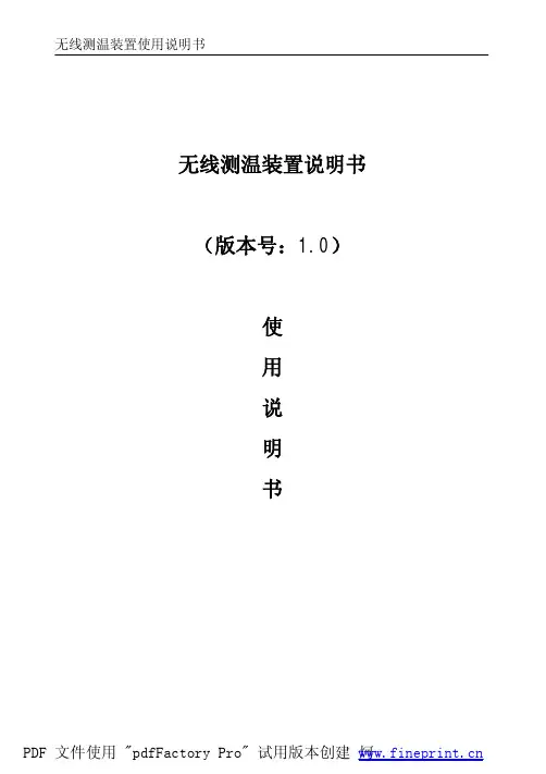
目录一、概述 (5)二、主要技术指标 (5)三、使用环境条件 (6)四、测量原理 (6)五、使用方法1、面板配置 (7)2、操作键盘 (7)3、开机 (8)4、仪器复位 (8)5、误差测试 (8)6、电网频率测试 (14)一、概述HGQY-H便携式低校高式电压互感器测试仪是最适合于在现场对电压互感器进行误差测试的全自动智能仪器。
用户不再需要配置笨重的升压器,标准电压互感器,负载箱及调压器(或自动检测台),单台仪器就能对10kV、10kV/3、35kV、35kV/3、110kV/3、220kV/3的电压互感器进行快速测量。
全过程(包括额定、下限的所有测量点)的测试时间不超过1分钟(不含接线时间),其准确度达到0.05级。
本仪器采用320×240点阵的大屏幕液晶显示器,各点的误差可以在同一屏上显示,所有操作均可点击屏幕菜单轻松完成。
本仪器可以存贮200组数据,备有专用接口与PC机通讯。
本仪器约重15kg。
二、主要技术指标●测试范围:10kV、10kV/3、35kV、35kV/3、110kV/3、220kV/3●二次负荷:2.5VA~600VA cosФ=0.8●测量精度:0.05级●测频率:准确度为0.01Hz●仪器设有实时时钟,可实时记录测试时间。
C1611CE500-220300S28V8电源使用说明书为确保用户正确使用新雷能电源产品,请仔细阅读本说明书。
本文简述了相关操作程序及注意事项,用户可根据实际情况有选择性地参照或进行适度调整。
如有疑问,用户可咨询新雷能技术支持工程师。
1 产品用途适用于电力配网自动化系统,电力智能箱变,环网柜以及其他行业需要不间断直流供电,要求较高的场合。
2 工作原理框图产品工作原理框图见图1。
1 工作原理框图图13 产品特性➢金属外壳模块化封装,体积小巧,防尘防震。
➢交直流双输入,原副边隔离,隔离强度高。
➢恒流充电,典型转换效率84%,抗干扰能力强,性能稳定。
➢单路输出,具有输出短路、输出过热、输入过压、输出过压等保护功能。
➢具有电池活化功能,手动或通过外部信号自动对电池进行活化维护。
➢具有电源状态指示功能。
➢端子方式连接,可直接安装,方便使用。
4 技术参数产品技术参数见表1。
表1 技术参数5 电源使用说明5.1 总述本电源可配用6A H~40A H锂电池进行充电。
请参见本说明接线示意图正确连接,注意切勿接错,否则将造成电源永久性损坏。
本电源在输入交流电后即可工作,电源本身对负载输出电流,同时为电池进行恒流恒压充电,电池充电完成后,电源自动转为浮充电状态,此时电源提供浮充电压及电流补充电池的正常自放电;交流断电时,电池不间断为负载供电,0切换时间,当电池放电至欠压告警点时,输出电池欠压告警信号,当电池放电低于欠压保护点时,电源自动关闭负载输出;如果需要提前关断电池输出,可手动按电池OFF键5 秒或遥控由C PU控制的继电器把电源的电池遥控退出端子B G与V G短接一次(不小于5秒)则电池提前关断。
当负载需要较大冲击电流,超出电源提供的最大电流时,电源自身保护关断,负载电流完全由电池提供,当负载电流小于电源提供的最大电流时,电源自动启动工作。
注意:电池提前退出功能在电池活化时禁止使用,否则将使负载短时断电。
电池提前退出后负载断电,此时只能手动恢复供电或交流恢复时重新供电。
CYRUSTEK ES5116 A/D CONVERTER Datasheet/cyrustek/es5116-a-d-converter-datasheet.htmlThe ES5116 is low power monolithic CMOS 3 1/2 digit LCD display A/D converter. It contains the internal clock, voltage reference,seven-segment decoders,LCD display drivers and a back plane driver. The improved internal zener reference voltage circuit gives the analog common a small temperature coefficient of typically. collects and classifies the global productinstrunction manuals to help users access anytime andanywhere, helping users make better use of products.Pin No.TypeDEEN De-integration statusflag.2OTEST Pull high to V+all LCD segments will be activated.4–HOLD Hold pin,pull high to hold display.6–OS1Crystal oscillator connection.8–D1LCD segment line.10OB1LCD segment line.12OF1LCD segment line.14OE1LCD segment line.16OC2LCD segment line.18OA2LCD segment line.4July21,2003continued from previous pagePin No.Type20OE2LCD segment line.22OB3LCD segment line.24OE3LCD segment line.26OPOL LCD segment line.28OG3LCD segment line.30OC3LCD segment line.32OLB Low-batteryflag segment driver.34–INT Integration cycle output.36OA.Z Auto-zero capacitor connection.38–INHI High analog input signal connection.40–C+REF Positive capacitor connection for on-chip DC-DC converter.42–REF LO Low differential reference input connection.44INote:1.Pin No.of QFP-44pin package.Absolute Maximum RatingsRatingSupply V oltage(to)toReference Input V oltage(either input)TEST toPower Dissipation(plastic package)C to CStorage TemperatureCParameter Test Condition Typ.Units Zero Input Reading Full-Scale=200.0mVDigital ReadingRatio-metric Reading=,=100mV999/1000Digital ReadingLinearity(Max.deviationfrom best straight linefit)full-Scale=200mV orFull-Scale=2.000VCountsroll-over Error=200.0mVCountsCommon Mode RejectionRatio=1V,=0VFull-Scale=200.0mV50uV/V Low batteryflag V+to V-7.0V Noise15uVp-p Input Leakage Current1pA Zero Reading Drift,C<=<=C0.2uV/CAnalog COMMON V oltage(with respect to V)25K BetweenCommon and Posi-tive Supply3.0VAnalog COMMON Temper-ature Coefficient25K BetweenCommon and,C<=TA<=C60ppm/CSegment Drive V oltage to=9V5V Back plane Drive V oltage to5V Supply Current(Does notinclude COMMON current)=0V0.6mACYRUSTEK CO.ES511631/2DVM withhold and low battery indication This Manual:/cyrustek/es5116-a-d-converter-datasheet.html。
SCF95509.5 mm x 5.0 mm Surface mount self-control fuseProduct features• Surface mount, 3 terminal fuse •Provides overcurrent and overcharging protection•Integrated thermal element provides triggerable operation• Ideal for battery powered electronics •A unique fusible device provides fast acting performance•Moisture sensitivity level (MSL): 1Applications• Notebook and laptop computing • Handheld electric power tools •Battery powered household appliancesAgency informationcURus recognition file number: E19180, Guide JDYX2 and JDYX8Environmental complianceSCF9550- 30 -01Family codeAmpere ratingNumber of cellsOrdering part numberEquivalent circuit diagramHALOGENHF FREE2Technical Data ELX1135Effective January 2022SCF9550 9.5 mm x 5.0 mm Surface mount self-control fuse/electronicsElectrical characteristicsCondition of testOpening time100% of current rating 1 hour minimum 200% of current rating 60 seconds maximum Operating voltage60 seconds maximumProduct specificationsCurrent rating Voltage rating 1Heater DCR Operating voltage Breaking capacity Fuse DCR Applicable Agency approval Part number (A)(Vdc)(Ω)(V)(A)(mΩ)cells in seriesPart MarkingcURusSCF9550-30-0130620.8 - 1.2 4.0 - 6.680 1.0 - 2.5130A1K √SCF9550-30-023062 1.1 - 2.3 5.6 - 9.080 1.0 - 2.5230A2K √SCF9550-30-033062 3.2 - 5.28.4 - 13.280 1.0 - 2.5330A3K √SCF9550-30-053062 4.8 - 8.010.5 - 23.580 1.0 - 2.54-530A4K √SCF9550-30-07306218.8 - 31.220.2 - 31.580 1.0 - 2.56-730A7K √SCF9550-30-08308024.0 - 52.026.4 - 36.080 1.0 - 2.5830A9K2SCF9550-30-10308040.0 - 60.028.0 - 47.080 1.0 - 2.51030A10K √SCF9550-30-12308035.0 - 70.033.6 - 54.080 1.0 - 2.51230A10K2SCF9550-30-13308065.0 - 100.036.2 - 58.580 1.0 - 2.51330A10K4SCF9550-30-14308040.0 - 60.028.0 - 62.080 1.0 - 2.510-1430A14K √SCF9550-30-17308059.0 - 120.042.0 - 74.880 1.0 - 2.515-1730A14K3SCF9550-30-08L 308010.0 - 20.020.0 - 30.080 1.0 - 2.58 LFP 30A9K2P SCF9550-30-14L 308036.0 - 60.035.0 - 51.880 1.0 - 2.514 LFP 30A14KP SCF9550-30-16L 308042.0 - 70.036.0 - 62.080 1.0 - 2.516 LFP 30A14K3P SCF9550-30-17L 308054.0 - 90.042.5 - 62.980 1.0 - 2.517 LFP 30A14K4P SCF9550-30-20L 308060.0 - 100.050.0 - 74.080 1.0 - 2.520 LFP 30A14K7P SCF9550-45-034580 1.9 - 2.99.8 - 13.51200.5 - 1.5345A3K √SCF9550-45-044580 3.4 - 5.113.0 - 18.41200.5 - 1.5445A4K √SCF9550-45-054580 5.6 - 8.416.7 - 23.51200.5 - 1.5545A5K √SCF9550-45-0645807.4 - 11.819.8 - 27.01200.5 - 1.5645A5K2SCF9550-45-07458010.0 - 15.022.3 - 31.51200.5 - 1.56-745A7K √SCF9550-45-08458014.4 - 21.526.7 - 37.61200.5 - 1.5845A8K √SCF9550-45-10458022.0 - 33.033.0 - 47.01200.5 - 1.59-1045A10K √SCF9550-45-14458038.5 - 75.047.2 - 62.01200.7 - 1.413-1445A14K √SCF9550-45-16458055.0 - 95.056.0 - 70.41200.7 - 1.41645A14K6SCF9550-45-17458064.0 - 104.059.5 - 76.01200.5 - 1.51745A14K4SCF9550-45-20458072.0 - 145.070.0 - 90.01200.5 - 1.52045A14K7SCF9550-45-14L 458027.0 - 41.036.4 - 51.81200.5 - 1.514 LFP 45A14KP SCF9550-45-15L 458029.2 - 48.440.0 - 54.01200.5 - 1.515 LFP 45A14K2P SCF9550-45-16L 458035.6 - 52.441.6 - 59.21200.5 - 1.516 LFP 45A14K3P SCF9550-45-17L 458039.6 - 59.244.2 - 62.91200.5 - 1.517 LFP 45A14K4P SCF9550-45-20L 458055.0 - 75.550.0 - 74.01200.5 - 1.520 LFP 45A14K7P SCF9550-45-24L458085.0 - 156.572.0 - 92.01200.5 - 1.524 LFP45A14K11P1. Rated voltage is the maximum voltage that the fuse can block, not the action voltage of the heater assembly3Technical Data ELX1135Effective January 2022SCF95509.5 mm x 5.0 mm Surface mount self-control fuse/electronics Dimensions- mm Drawing not to scaleRecommended pad layoutPart marking1. Rated current: 30A, 45A2. Number related to series number3. Length width size code: K: 9.5 × 5.0 mm4. Extension for (2)5. Year: D: 2018; E: 2019……6. Week of year: 01, 02……527. Running number: 01, 02……4Technical Data ELX1135Effective January 2022SCF9550 9.5 mm x 5.0 mm Surface mount self-control fuse/electronicsGeneral specificationsOperating temperature: -20 °C to +60 °C Storage temperature: -10 °C to +40 °C < 90% RH Storage duration: 1 yearHigh temperature: +105 °C @ 1000 hours Humidity: +85 °C @ 85% RH @ 500 hours Low temperature: -40 °C @ 500 hoursPackaging information- mmSupplied in tape and reel packaging, 3000 parts per 13” diameter reel. (EIA-481 compliant)Code(mm)E1 1.75 ± 0.10F 7.50 ± 0.10P2 2.00 ± 0.10D0 1.50 + 0.1/-0D1 1.50 + 0.1/-0P0 4.00 ± 0.1010P040.0 ± 0.20W 16.00 ± 0.30P 8.00 ± 0.10A0 5.3 ± 0.10B09.8 ± 0.10K0 2.3 ± 0.10T0.30 ± 0.05Direction of tapingThe direction shall be seen from the top cover tape sideEatonElectronics Division 1000 Eaton Boulevard Cleveland, OH 44122United States/electronics© 2022 EatonAll Rights Reserved Printed in USAPublication No. ELX1135 BU-ELX21143January 2022Technical Data ELX1135Effective January 2022SCF95509.5 mm x 5.0 mm Surface mount self-control fuse Life Support Policy: Eaton does not authorize the use of any of its products for use in life support devices or systems without the express writtenapproval of an officer of the Company. Life support systems are devices which support or sustain life, and whose failure to perform, when properly used in accordance with instructions for use provided in the labeling, can be reasonably expected to result in significant injury to the user.Eaton reserves the right, without notice, to change design or construction of any products and to discontinue or limit distribution of any products. Eaton also reserves the right to change or update, without notice, any technical information contained in this bulletin.Solder reflow profileEaton is a registered trademark.All other trademarks are property of their respective owners.Follow us on social media to get thelatest product and support information.。
JDC160E说明书E1JDC160E是一款可以运行在 UPS和3 A领域内的高端品牌,拥有着众多的忠实用户。
本机支持 WIFI、 NFC以及 MIN (可拓展存储卡)等移动设备的连接方式,可连接到 UPS、3 A等无线网络。
同时本机也可以作为电脑服务器使用。
JDC160E配备了多个 USB接口以及多个RS485接口,最大支持8 G内存卡。
另外配有硬盘以及内存,为用户提供更好的服务。
JDC160E最大工作电压为3.3 V (不支持过压保护),采用12 V工作电压供电,额定功率为40 W。
根据 IEC 62688 (2009)《无线充电适配器术语》中条款定义,该设备“用于在任何可能条件下”实现无线充电功能的适配器必须符合 IEC 62688-2,“应与本机配套使用并且符合 IEC 62488-3要求”;因此,对于不使用无线充电设备的用户而言不能安装任何与本机配套所用的适配器(例如移动电源)在额定功率下运行。
1、无线充电适配器必须通过 IEC 62688的认证。
(1)申请认证前:必须先获得认证。
获得认证前,必须向相关方提供有关该适配器符合性的报告。
(2)认证过程:由获得 IEC 62688认证资格的工程师对产品进行测试并出具报告。
(3)检测时间:对于没有获得认证状态下,若产品没有满足 IEC 62688的规定,产品将会被判定为不符合要求;如果产品已符合 IEC 62688规定,且不会因为此产品不能通过测试而被拒绝发货;如产品不符合规定要求,可以更换或维修产品。
2、无线充电适适配器必须通过 TUV的认证,在输入电压允许范围内(最高允许电流为0 mA)进行无线充电。
由于无线充电适配器所搭载的电荷泵是采用交流电源的形式,因此无线充电接口在电源开关打开状态时需要一定的输入电压,这样就可以保证在输入电压低于1 V后自动断开该适配器电源并输出电流为0 mA,达到0 mA条件下才可工作。
但如果你使用交流电泵进行供电时,其会发生损坏和产生漏电现象。
SUP-5116M使用手册浙江中控技术股份有限公司声 明⏹ 严禁转载本手册的部分或全部内容。
⏹ 在不经预告和联系的情况下,本手册的内容有可能发生变更,请谅解。
⏹本手册所记载的内容,不排除有误记或遗漏的可能性。
如对本手册内容有疑问,请与我公司联系。
文档标志符定义警告:标示有可能导致人身伤亡或设备损坏的信息。
WARNING : Indicates information that a potentially hazardous situation which, if not avoided, could result in serious injury or death.电击危险:标示有可能产生电击危险的信息。
Risk of Electrical Shock: Indicates information that Potential shock hazard where HAZARDOUS LIVE voltages greater than 30V RMS, 42.4V peak, or 60V DC may be accessible.防止静电:标示防止静电损坏设备的信息。
ESD HAZARD: Indicates information that Danger of an electro-static discharge to which equipment may be sensitive. Observe precautions for handling electrostatic sensitive devices注意:提醒需要特别注意的信息。
ATTENTION: Identifies information that requires special consideration.提示:标记对用户的建议或提示。
TIP :Identifies advice or hints for the user.设备安全警示标志下表列出了在设备中使用的安全警示标志符号及描述。