奇美7寸液晶屏AT070TN83 规格书
- 格式:pdf
- 大小:634.21 KB
- 文档页数:28

Technical DataPanelView Plus 7 Performance TerminalsCatalog Numbers 2711P-T7C22D9P , 2711P-T7C22D9P-B, 2711P-T7C22A9P , 2711P-T7C22A9P-B, 2711P-B7C22D9P , 2711P-B7C22D9P-B, 2711P-B7C22A9P, 2711P-B7C22A9P-B, 2711P-T9W22D9P , 2711P-T9W22D9-B, 2711P-T9W22A9P , 2711P-T9W22A9P-B, 2711P-T10C22D9P , 2711P-T10C22D9P-B, 2711P-T10C22A9P, 2711P-T10C22A9P-B, 2711P-B10C22D9P , 2711P-B10C22D9P-B, 2711P-B10C22A9P , 2711P-B10C22A9-B, 2711P-T12W22D9P , 2711P-T12W22D9P-B, 2711P-T12W22A9P , 2711P-T12W22A9P-B, 2711P-T15C22D9P , 2711P-T15C22D9P-B, 2711P-T15C22A9P , 2711P-T15C22A9P-B, 2711P-B15C22D9P , 2711P-B15C22D9P-B, 2711P-B15C22A9P , 2711P-B15C22A9P-B, 2711P-T19C22D9P , 2711P-T19C22D9P-B, 2711P-T19C22A9P , 2711P-T19C22A9P-BSummary of ChangesThe PanelView™ Plus 7 Performance terminals are operator interface devices. They monitor and control devices that are attached to ControlLogix® and CompactLogix™ 5370controllers on an EtherNet/IP network. Animated graphic and text displays provide operators a view into the operating state of a machine or process. Operators interact with the control system by using touch screen or keypad input.TopicPage Environmental Specifications 2Certifications 3Technical Specifications 4Product Dimensions 7Accessories 8HMI Software 9Additional Resources10TopicPage Updated system memory to 512 MB RAM and 512 MB storage.Updated user memory to 80 MB, approx, nonvolatile storage for applications.4, 5, 62Rockwell Automation Publication 2711P-TD009C-EN-P - July 2016PanelView Plus 7 Performance TerminalsFeatures include the following:•FactoryTalk® View Machine Edition software, version 8.1, provides a familiar environment for creating HMI applications•Windows CE operating system with desktop access for configuration and third-party applications •Connection to ControlLogix or CompactLogix 5370 controllers•Ethernet communication that can support Device Level Ring (DLR), linear, or star network topologies•W eb browser, Microsoft file viewers, text editor, PDF viewer, remote desktop connection, and media player on the terminal desktopEnvironmental SpecificationsThis table lists environmental specifications for the PanelView Plus 7 Performance terminals.AttributeValueTemperature, operating (1)(1)The 19-inch terminals (2711P-T19C22D9P , 2711P-T19C22D9P-B, 2711P-T19C22A9P , and 2711P-T19C22A9P-B) are rated up to 50 °C (122 °F) operating temperature.0…55 °C (32…131 °F)Temperature, nonoperating-25…+70 °C (-13…+158 °F)Heat dissipation (2)(2)Typical BTU measurements were taken at 25 °C (77 °F).7-in. DC (touch, and touch with keypad), 51 BTU (typical)7-in. AC (touch, and touch with keypad), 53 BTU (typical)9-in. DC, 55 BTU (typical)9-in. AC, 58 BTU (typical)10-in. DC (touch, and touch with keypad), 51 BTU (typical)10-in. AC (touch, and touch with keypad), 56 BTU (typical)12-in. DC, 60 BTU (typical)12-in. AC, 67 BTU (typical)15-in. DC (touch, and touch with keypad), 61 BTU (typical)15-in. AC (touch, and touch with keypad), 68 BTU (typical)19-in. DC, 114 BTU (typical)19-in. AC, 119 BTU (typical)Altitude, operating 2000MRelative humidity 5…95% without condensation Vibration 0.012 pk-pk, 10…57 Hz 2 g peak at 57…500 Hz (3)(3)The 15-inch and 19-inch terminals (2711P-T15C22D9P , 2711P-T15C22D9P-B, 2711P-T15C22A9P , 2711P-T15C22A9P-B, 2711P-B15C22D9P , 2711P-B15C22D9P-B,2711P-B15C22A9P , 2711P-B15C22A9P-B, 2711P-T19C22D9P , 2711P-T19C22D9P-B, 2711P-T19C22A9P , 2711P-T19C22A9P-B) are rated to: 0.006 in. pk-pk, 10...57 Hz, 1 g peak at 57...640 Hz.Shock, operating 15 g at 11 ms Shock, nonoperating 30 g at 11 msEnclosure ratingsNEMA and UL Type 12, 13, 4X, also rated IP66 as Classified by ULRockwell Automation Publication 2711P-TD009C-EN-P - July 20163PanelView Plus 7 Performance TerminalsCertificationsThis table lists certifications for the PanelView Plus 7 Performance terminals.Certification (1)(1)When marked. See the Product Certification link at /global/certification/overview.page for Declarations of Conformity, Certificates, and othercertification details.ValuecULuscULus Listed Industrial Control Equipment for use in Hazardous Locations (E10314) per standards ANSI / ISA 12.12.01 and CSA C22.2 No. 213. rated:•Class I, Div 2, Groups A, B, C, DEnclosure type ratings per UL50 and CSA C22.2 No. 94.2-07. Enclosure ingress protection classified by UL per IEC 60529.CE (EMC)European Union 2004/108/EC EMC Directive, compliant with:•EN 61000-6-2; Industrial Immunity •EN 61000-6-4; Industrial Emissions •EN 61131-2; Programmable ControllersCE (LVD)European Union 2006/95/EC Low Voltage Directive, compliant with:•EN 61131-2; Programmable Controllers RCM Australian Radiocommunications Act, compliant with:•AS/NZS CISPR 11; Industrial Emissions RoHS China RoHS, Turkey RoHS, European RoHS KCC Certificate of complianceEtherNet/IPODVA conformance tested to EtherNet/IP specifications4Rockwell Automation Publication 2711P-TD009C-EN-P - July 2016PanelView Plus 7 Performance TerminalsTechnical SpecificationsThe tables in this section provide technical specifications for the PanelView Plus 7 Performance terminals.PanelView Plus 7 Performance 7-in and 9-in TerminalsAttribute 7-in. Touch2711P--T7C22D9P , 2711P--T7C22D9P-B (1)2711P-T7C22A9P , 2711P-T7C22A9P-B (1)Catalog numbers with a -B extension denote terminals that exclude the Allen-Bradley brand marking. Customers can put their own brand labels on these terminals.7-in. Touch with Keypad2711P-B7C22D9P , 2711P-B7C22D9P-B (1)2711P-B7C22A9P , 2711P-B7C22A9P-B 9-in. Touch2711P-T9W22D9P, 2711P-T9W22D9P-B (1)2711P-T9W22A9P , 2711P-T9W22A9P-BOperator input Touch Touch with keypadTouchDisplay type TFT Color Display size, diagonal 6.5-in.9-in. widescreen Viewing area (W x H)132 x 99 mm (5.2 x 3.9 in.)196 x 118 mm (7.7 x 4.6 in.)Display resolution 640 x 480 VGA, 18-bit color graphics 800 x 480 WVGA, 18-bit color graphics Aspect ratio 4:3 5:3Brightness, typical 300 cd/m 2 (Nits)Backlight lifeWhite light-emitting diode, solid-stateLife: 50,000 h min at 40 °C (104 °F) to half-brightness, backlight is not replaceable Touch screenAnalog resistiveActuation rating: 1 million presses Operating force: 100 grams Battery (real-time clock backup)Accuracy: +/-2 minutes per month.Battery life: 4 years min at 25 °C (77 °F)Replacement: CR2032 lithium coin cellMemory:•System •User •512 MB RAM and 512 MB storage•80 MB, approx, nonvolatile storage for applicationsSecure Digital (SD) card slot One SD card slot for external storage; supports cat. no. 1784-SD x cardsUSB ports:•Host •Device •Two USB high-speed 2.0 host ports (type A) support removable flash drives for external storage •One high-speed 2.0 device port (type B) that will be functional in a future releaseOperating system Windows CE with Extended Features and MS Office Viewers (includes FTP , VNC client server, ActiveX controls, PDF reader, third-party device support)Ethernet ports Two 10/100Base-T, Auto MDI/MDI-X Ethernet ports that support Device Level Ring (DLR), linear, or star network topologies Software FactoryTalk View Studio for Machine Edition, FactoryTalk ViewPoint, version 2.6 or laterElectrical Input voltage 24V DC nom (18…30V DC)100…240V AC 24V DC nom (18…30V DC)100…240V AC 24V DC nom (18…30V DC)100…240V AC Power consumption 50 W max(2.1 A at 24V DC)105VA 50 W max(2.1 A at 24V DC)105VA 50 W max(2.1 A at 24V DC)105VA Power supply Supports (SELV) and (PELV) 24V DC supplies (2)(2)DC-powered terminals support safety extra low voltage (SELV) and protective extra low voltage (PELV) 24V DC power supplies such as cat. nos. 1606-XLP95E, 1606-XLP100E, 2711P-RSACDIN.—Supports (SELV) and (PELV) 24V DC supplies (2)—Supports (SELV) and (PELV) 24V DC supplies (2)—Mechanical Weight, approx 1.2 kg (2.65 lb) 1.47 kg (3.25 lb) 1.58 kg (3.48 lb)Dimensions, approx (H x W x D)170 x 212 x 69.6 mm 6.69 x 8.35 x 2.74 in.179 x 285 x 69.6 mm 7.05 x 11.22 x 2.74 in.190 x 280 x 69.6 mm 7.48 x 11.02 x 2.74 in.Cutout dimensions, approx (H x W)142 x 184 mm 5.59 x 7.24 in.142 x 237 mm 5.59 x 9.33 in.162 x 252 mm 6.38 x 9.92 in.Rockwell Automation Publication 2711P-TD009C-EN-P - July 20165PanelView Plus 7 Performance TerminalsPanelView Plus 7 Performance 10-in and 12-in TerminalsAttribute 10-in. Touch2711P-T10C22D9P, 2711P-T10C22D9P-B (1)2711P-T10C22A9P , 2711P-T10C22A9P-B (1)Catalog numbers with a -B extension denote terminals that exclude the Allen-Bradley brand marking. Customers can put their own brand labels on these terminals.10-in. Touch with Keypad2711P-B10C22D9P , 2711P-B10C22D9P-B (1)2711P-B10C22A9P , 2711P-B10C22A9P-B 12-in. Touch2711P-T12W22D9P , 2711P-T12W22D9P-B (1)2711P-T12W22A9P , 2711P-T12W22A9P-B Operator input Touch Touch with keypadTouchDisplay type TFT Color Display size, diagonal 10.4-in.12.1-in.Viewing area (W x H)211 x 158 mm (8.3 x 6.2 in.)261 x 163 mm (10.3 x 6.4 in.)Display resolution 800 x 600 SVGA, 18-bit color graphics 1280 x 800 WXGA, 18-bit color graphics Aspect ratio 4:316:10Brightness, typical 300 cd/m 2 (Nits)Backlight lifeWhite light-emitting diode, solid-stateLife: 50,000 h min at 40 °C (104 °F) to half-brightness, backlight is not replaceable Touch screenAnalog resistiveActuation rating: 1 million presses Operating force: 100 grams Battery (real-time clock backup)Accuracy: +/-2 minutes per month.Battery life: 4 years min at 25 °C (77 °F)Replacement: CR2032 lithium coin cellMemory:•System •User •512 MB RAM and 512 MB storage•80 MB, approx, nonvolatile storage for applicationsSecure Digital (SD) card slot One SD card slot for external storage; supports cat. no. 1784-SD x cardsUSB ports:•Host •Device •Two USB high-speed 2.0 host ports (type A) support removable flash drives for external storage •One high-speed 2.0 device port (type B) that will be functional in a future releaseOperating system Windows CE with Extended Features and MS Office Viewers (includes FTP , VNC client server, ActiveX controls, PDF reader, third-party device support)Ethernet ports Two 10/100Base-T, Auto MDI/MDI-X Ethernet ports that support Device Level Ring (DLR), linear, or star network topologies Software FactoryTalk View Studio for Machine Edition, FactoryTalk ViewPoint, version 2.6 or laterElectrical Input voltage 24V DC nom (18…30V DC)100…240V AC 24V DC nom (18…30V DC)100…240V AC 24V DC nom (18…30V DC)100…240V AC Power consumption 50 W max(2.1 A at 24V DC)105VA 50 W max(2.1 A at 24V DC)105VA 50 W max(2.1 A at 24V DC)105VA Power supply Supports (SELV) and (PELV) 24V DC supplies (2)(2)DC-powered terminals support safety extra low voltage (SELV) and protective extra low voltage (PELV) 24V DC power supplies such as cat. nos. 1606-XLP95E, 1606-XLP100E, 2711P-RSACDIN.—Supports (SELV) and (PELV) 24V DC supplies (2)—Supports (SELV) and (PELV) 24V DC supplies (2)—Mechanical Weight, approx 2.28 kg (5.03 lb) 2.58 kg (5.69 lb) 2.54 kg (5.60 lb)Dimensions, approx (H x W x D)252 x 297 x 69.6 mm 9.92 x 11.69 x 2.74 in.252 x 385 x 69.6 mm 9.92 x 15.16 x 2.74 in.240 x 340 x 69.6 mm 9.69 x 13.39 x 2.74 in.Cutout dimensions, approx (H x W)224 x 269 mm 8.82 x 10.59 in.224 x 335 mm 8.82 x 13.19 in.218 x 312 mm 8.58 x 12.28 in.6Rockwell Automation Publication 2711P-TD009C-EN-P - July 2016PanelView Plus 7 Performance TerminalsPanelView Plus 7 Performance 15-in and 19-in TerminalsAttribute 15-in. Touch2711P-T15C22D9P , 2711P-T15C22D9P-B (1)2711P-T15C22A9P , 2711P-T15C22A9P-B (1)Catalog numbers with a -B extension denote terminals that exclude the Allen-Bradley brand marking. Customers can put their own brand labels on these terminals.15-in. Touch with Keypad2711P-B15C22D9P, 2711P-B15C22D9P-B (1)2711P-B15C22A9P , 2711P-B15C22A9P-B 19-in. Touch2711P-T19C22D9P , 2711P-T19C22D9P-B (1)2711P-T19C22A9P, 2711P-T19C22A9P-B Operator input Touch Touch with keypadTouchDisplay type TFT Color Display size, diagonal 15-in.19-in.Viewing area (W x H)304 x 228 mm (12.0 x 9.0 in.)376 x 301 mm (14.8 x 11.9 in.)Display resolution 1024 x 768 XGA, 18-bit color graphics 1280 x 1024 SXGA, 18-bit color graphics Aspect ratio 4:35:4Brightness, typical 300 cd/m 2 (Nits)Backlight lifeWhite light-emitting diode, solid-stateLife: 50,000 h min at 40 °C (104 °F) to half-brightness, backlight is not replaceable Touch screenAnalog resistiveActuation rating: 1 million presses Operating force: 100 grams Battery (real-time clock backup)Accuracy: +/-2 minutes per month.Battery life: 4 years min at 25 °C (77 °F)Replacement: CR2032 lithium coin cellMemory:•System •User •512 MB RAM and 512 MB storage•80 MB, approx, nonvolatile storage for applicationsSecure Digital (SD) card slot One SD card slot for external storage; supports cat. no. 1784-SD x cardsUSB ports:•Host •Device •Two USB high-speed 2.0 host ports (type A) support removable flash drives for external storage •One high-speed 2.0 device port (type B) that will be functional in a future releaseOperating system Windows CE with Extended Features and MS Office Viewers (includes FTP , VNC client server, ActiveX controls, PDF reader, third-party device support)Ethernet ports Two 10/100Base-T, Auto MDI/MDI-X Ethernet ports that support Device Level Ring (DLR), linear, or star network topologies Software FactoryTalk View Studio for Machine Edition, FactoryTalk ViewPoint, version 2.6 or laterElectrical Input voltage, DC 24V DC nom (18…30V DC)100…240V AC 24V DC nom (18…30V DC)100…240V AC 24V DC nom (18…30V DC)100…240V AC Power consumption, DC 50 W max(2.1 A at 24V DC)105VA 50 W max(2.1 A at 24V DC)105VA 50 W max(2.1 A at 24V DC)105VA Power supply Supports (SELV) and (PELV) 24V DC supplies (2)(2)DC-powered terminals support safety extra low voltage (SELV) and protective extra low voltage (PELV) 24V DC power supplies such as cat. nos. 1606-XLP95E, 1606-XLP100E, 2711P-RSACDIN.—Supports (SELV) and (PELV) 24V DC supplies (2)—Supports (SELV) and (PELV) 24V DC supplies (2)—Mechanical Weight, approx 3.69 kg (8.14 lb) 4.14 kg (9.13 lb) 5.62 kg (12.40 lb)Dimensions, approx (H x W x D)318 x 381 x 69.6 mm 12.52 x 15.00 x 2.74 in 329 x 484 x 69.6 mm 12.95 x 19.06 x 2.74 in 411 x 485 x 69.6 mm 16.18 x 19.09 x 2.74 in Cutout dimensions, approx (H x W)290 x 353 mm 11.42 x 13.90 in290 x 418 mm 11.42 x 16.46 in383 x 457 mm 15.08 x 17.99 inRockwell Automation Publication 2711P-TD009C-EN-P - July 20167PanelView Plus 7 Performance TerminalsProduct DimensionsThe table provides product dimensions. The 10.4-inch touch and combination keypad with touch devices are shown for illustrative purposes. All other terminal sizes look similar.PanelView Plus 7 Performance Dimensions - 10.4-in. ModelProduct Dimensions - PanelView Plus 7 Performance TerminalsTerminal Size Input Type Height (a)mm (in.)Width (b)mm (in.)Overall Depth (c)mm (in.)Mounted Depth (d)mm (in.)6.5-in.Key/touch 179 (7.05)285 (11.22)69.6 (2.74)63.6 (2.50)Touch 170 (6.69)212 (8.35)9-in.Touch 190 (7.48)280 (11.02)10.4-in.Key/touch 252 (9.92)385 (15.16)Touch 252 (9.92)297 (11.69)12.1-in.Touch 246 (9.69)340 (13.39)15-in.Key/touch 329 (12.95)484 (19.06)Touch 318 (12.52)381 (15.00)19-in.Touch411 (16.18)485 (19.09)TIPWhen mounted in a panel, the front of the bezel extends less than 6.36 mm (0.25 in.) from the front of the panel.b8Rockwell Automation Publication 2711P-TD009C-EN-P - July 2016PanelView Plus 7 Performance TerminalsAccessoriesThe tables in this section list accessories for the PanelView Plus 7 Performance terminals.Protective OverlaysPower Supplies and Power Terminal BlocksMounting HardwareSecure Digital (SD) CardsBattery ReplacementCat. No.(1)(1)Three overlays are shipped with each catalog number.Display Size Operator Input Touch Key and Touch2711P-RGT7SP 6.5-in.•2711P-RGB7P •2711P-RGT9SP 9-in. (wide)•2711P-RGT10SP 10.4-in.•2711P-RGB10P •2711P-RGT12SP 12.1-in. (wide)•2711P-RGT15SP 15-in.•2711P-RGB15P •2711P-RGT19P19-in.•Cat. No.DescriptionQuantity1606-XLP95E DIN rail power supply, 24…28V DC output voltage, 95 W 11606-XLP100E DIN rail power supply, 24…28V DC output voltage, 100 W 12711P-RSACDIN DIN rail power supply, AC-to-DC, 85…265V AC, 47…63 Hz 12711P-RTBAP 3-pin AC power terminal block 102711P-RTBDSP3-pin DC power terminal block10Cat. No.Description Quantity 2711P-RMCP (1)(1)Catalog number 2711P-RMCP mounting levers are used with PanelView Plus 7 Performance terminals. Do not use gray mounting levers; they are notcompatible with PanelView Plus 7 Performance terminals.Mounting levers (black)16Cat. No.Description 1784-SD1 1 GB SD card 1784-SD2 2 GB SD card2711C-RCSDUSB to SD adapter for SD cardCat. No.DescriptionQuantity2711P-RY2032Lithium coin cell battery, CR2032 equivalent1Rockwell Automation Publication 2711P-TD009C-EN-P - July 20169PanelView Plus 7 Performance TerminalsHMI SoftwareAll PanelView Plus 7 terminals are configured with FactoryTalk View Studio software and have an integrated runtime system called FactoryTalk View Machine Edition Station.Machine Edition Station runs projects that are developed with FactoryTalk View Studio software and is included on all PanelView Plus 7 terminals.Two versions of FactoryTalk View Studio software support application development for PanelView Plus 7 terminals.Y ou can import PanelView Standard/PanelBuilder® 32 and PanelView applications into FactoryTalk View Studiosoftware as Machine Edition applications by using the Machine Edition Import Wizard. The Import Wizard steps you through a few options such as scaling to a new screen resolution size, and then converts objects, text, tags, and communication configurations to ones that are available in Machine Edition.FactoryTalk ViewPoint software, an add-on to FactoryTalk View Studio software, allows plant managers, production supervisors, system integrators, and other key stakeholders to view and control real-time plant floor operations remotely from a web browser. FactoryTalk ViewPoint enabled displays are fully scalable and animated in the browser. The remote user can also view displays that are not the active display of the terminal.Each PanelView Plus 7 terminal contains one license that supports one client connection to the terminal. No additional software is required.For a complete list of available HMI software, visit /rockwellsoftware .Cat. No.(1)(1)To order localized versions of the software, replace EN in the catalog number with DE for German, FR for French, JP for Japanese, or ZH for Chinese.Description9701-VWSTMENEFactoryTalk View Studio for Machine Edition software - Configuration software for developing and testingmachine-level human machine interface (HMI) applications. Includes RSLinx® Enterprise and KEPServer Enterprise software.9701-VWSTENEFactoryTalk View Studio software - Configuration software for developing and testing machine-level and supervisory-level human machine interface (HMI) applications.10Rockwell Automation Publication 2711P-TD009C-EN-P - July 2016PanelView Plus 7 Performance TerminalsAdditional ResourcesThese documents contain more information about related products from Rockwell Automation.Y ou can view or download publications at /global/literature-library/overview.page . T o order paper copies of technical documentation, contact your local Allen-Bradley distributor or Rockwell Automation sales representative.ResourceDescriptionPanelView Plus 7 Performance Terminals User Manual, publication 2711P-UM008 Provides instructions on how to install, configure, and operate the PanelView Plus 7 Performance terminals.Industrial Automation Wiring and Grounding Guidelines, publication 1770-4.1 Provides general guidelines on how to install a Rockwell Automation industrial system.Product Certifications website, /global/certification/overview.pageProvides declarations of conformity, certificates, and other certification details.PanelView Plus 7 Performance Terminals Notes:Rockwell Automation Publication 2711P-TD009C-EN-P - July 201611Allen-Bradley, CompactLogix, ControlLogix, FactoryTalk, PanelBuilder, PanelView, LISTEN. THINK. SOLVE, Rockwell Automation, Rockwell Software, and RSLinx are trademarks of Rockwell Automation, Inc.Trademarks not belonging to Rockwell Automation are property of their respective companies.Publication 2711P-TD009C-EN-P - July 2016Supersedes Publication 2711P-TD009B-EN-P - May 2016Copyright © 2016 Rockwell Automation, Inc. All rights reserved. Printed in the U.S.A.Rockwell Automation SupportUse the following resources to access support information.Documentation FeedbackY our comments will help us serve your documentation needs better. If you have any suggestions on how to improve this document, complete the How Are W e Doing? form at /idc/groups/literature/documents/du/ra-du002_-en-e.pdf .Technical Support CenterKnowledgebase Articles, How-to Videos, FAQs, Chat, User Forums, and Product Notification /knowledgebase Local Technical Support Phone NumbersLocate the phone number for your /global/support/get-support-now.page Direct Dial CodesFind the Direct Dial Code for your product. Use the code to route your call directly to a technical support /global/support/direct-dial.page Literature LibraryInstallation Instructions, Manuals, Brochures, and Technical /literature Product Compatibility and Download Center(PCDC)Get help determining how products interact, check features and capabilities, and find associated /global/support/pcdc.pageRockwell Otomasyon Ticaret A.Ş., Kar Plaza İş Merkezi E Blok Kat:6 34752 İçerenköy, İstanbul, T el: +90 (216) 5698400Rockwell Automation maintains current product environmental information on its website at /rockwellautomation/about-us/sustainability-ethics/product-environmental-compliance.page .。

ITEM CONTENTS UNIT LCD Type TFT/Transmissive/Normally Black/IPS / Size 7.0 Inch Viewing Direction Free / Outside Dimensions (W x H x D) 181.60 x 100.60 x 17.75 mm Active Area (W x H) 154.21 x 85.92 mm Pixel Pitch (W x H) 0.1506 x 0.1432 mm Resolution 1024 x 600 / Brightness 1000 cd/m 2 Color Depth 16.7 M / Pixel Arrangement RGB Vertical Stripe / Driver IC of Board STM32H747XIH6 / External SDRAM 64Mbit (32-bit access) / External Flash Memory 512Mbit / Supply Voltage for Module 6.0 - 36.0 V With/Without Touch Without Touch Panel / Weight TBD g STM32 EMBEDDED 7.0" DISPLAY DATASHEET RVT70HSSFWN00 Rev.0.1 2022-03-28 F T M O D U L E S P E C I F I C A T I O N Note 1: RoHS3 compliant Note 2: LCM weight tolerance: ± 5%.REVISION RECORDREV NO. REV DATE CONTENTS REMARKS0.1 2022-03-28 Preliminary versionCONTENTSREVISION RECORD (2)CONTENTS (3)MODULE CLASSIFICATION INFORMATION (4)ASSEMBLY GUIDE (5)MODULE DRAWING (6)ABSOLUTE MAXIMUM RATINGS (7)ELECTRICAL CHARACTERISTICS (7)BACKLIGHT ELECTRICAL CHARACTERISTICS (7)ELECTRO-OPTICAL CHARACTERISTICS (8)BOARD INTERFACES AND CONNECTORS (10)USER INTERFACES (16)DISPLAY SEPCIFICATION (17)INSPECTION (17)RELIABILITY TEST (19)LEGAL INFORMATION (20)MODULE CLASSIFICATION INFORMATIONRV T 70 H S S F W N 00 1. 2. 3. 4. 5. 6. 7. 8. 9. 10.ASSEMBLY GUIDEMounting frameFor dimensions 3.5”, 4.3”, 5.0”, 7.0” and 10.1”, the product with mounting frame version is available. Thanks to the four catches attached to the side, frame provides strong assembly to the surface by mounting element (like the screw, see Figure 1). The frames are specially designed to fit Riverdi products perfectly. The diameter of the mounting hole is 3.5mm.Figure 1. Mounting frameABSOLUTE MAXIMUM RATINGSPARAMETER SYMBOL MIN MAX UNIT NOTESupply Voltage for Module VDD 0.0 48.0V Note 1Digital I/O signals Voltage - -0.5 3.3 Note 1,2Operating Temperature T OP-20 70 °CStorage Temperature T ST-30 80 °CStorage Humidity (@ 25 ± 5°C) H ST10 - % RHOperating Ambient Humidity (@ 25 ± 5°C) H OP10 - % RHNote 1. Exceeding maximum values may cause improper operation or permanent damageto the unit.Note 2. Most of the GPIOs have the 5.0 V tolerant input voltage, please refer to the datasheetof STM32H747XIH6 for more details.ELECTRICAL CHARACTERISTICSPARAMETER SYMBOL MIN TYP MAX UNIT Supply Voltage for Module VDD_IN 6.0 12.0 36.0 VPOWER‘ENABLE’ = ‘0’***************************I VDD_IN=6.0 V TBD TBD TBD uA ****************************I VDD_IN=12.0 V TBD TBD TBD uA ****************************I VDD_IN=24.0 V TBD TBD TBD uA ****************************I VDD_IN=36.0 V TBD TBD TBD uAPOWER‘ENABLE’ = ‘1’***************************I VDD_IN=6.0 V TBD TBD TBD mA ****************************I VDD_IN=12.0 V TBD TBD TBD mA ****************************I VDD_IN=24.0 V TBD TBD TBD mA ****************************I VDD_IN=36.0 V TBD TBD TBD mAInput Voltage “H” Level V IH 2.0 - 3.3 V Input Voltage “L” Level V IL 0 - 0.8 V Note. POWER ‘ENABLE’ refers to pin 4, ‘ENABLE’ of the power input connector(P2).By default, POWER ‘ENABLE’ = ‘1’,When POWER ‘ENABLE’ = ‘0’, the device is turned off.BACKLIGHT ELECTRICAL CHARACTERISTICSPARAMETER SYMBOL MIN TYP MAX UNIT NOTE Lifetime - - 50,000 - hours Note 1Note 1. Operating life means the period in which the LED brightness goes down to 50% ofthe initial brightness. Typical operating lifetime is the estimated parameter.ELECTRO-OPTICAL CHARACTERISTICSITEM SYMBOL CONDITION MIN TYP MAX UNIT RMK NOTEResponse Time Tr+Tfθ=0°∅=0° - 35 35 ms FIG 2. 4Contrast Ratio Cr 800 1000 - --- FIG 3. 1 Luminance δ- 75 - % FIG 3. 3 Figure 3.Contrast Ratio =Average Surface Luminance with all white pixels (P1,P2,P3,P4,P5) Average Surface Luminance with all black pixels (P1,P2,P3,P4,P5)Note 2.Surface luminance is the LCD surface from the surface with all pixels displaying white. For more information see Figure 3.Lv = Average Surface Luminance with all white pixels (P1, P2, P3, P4, P5)Note 3.The uniformity in surface luminance δWHITE is determined by measuring luminance at each test position 1 through 5, and then dividing the minimum luminance of 5 points luminance by maximum luminance of 5 points luminance. For more information see Figure 3.δ WHITE =Minimum Surface Luminance with all white pixels (P1,P2,P3,P4,P5) Maximum Surface Luminance with all white pixels (P1,P2,P3,P4,P5)Note 4. Response time is the time required for the display to transition from white to black (Rise Time, Tr) and from black to white (Decay Time, Tf). For additional information see Figure 2. The test equipment is Autronic-Melchers’s ConoScope series.Note 5. CIE (x, y) chromaticity, the x, y value is determined by measuring luminance at each test position 1 through 5, and then calculating the average value.Note 6. Viewing angle is the angle at which the contrast ratio is greater than 2. For TFT module the contrast ratio is greater than 10. The angles are determined for the horizontal or x axis and the vertical or y axis with respect to the z axis which is normal to LCD surface. For more information see Figure 4.Note 7. For viewing angle and response time testing, the testing data is based on Autronic-Melchers’s ConoScope series. Instruments for Contrast Ratio, Surface Luminance, Luminance Uniformity, CIE the test data is based on TOPCON’s BM-5 photo detector.Figure 2. The definition of response timeFigure 3. Measuring method for Contrast ratio, surface luminance, Luminance uniformity, CIE (x, y) chromaticityA: 5mmB: 5mmH, V: Active AreaLight spot size ∅=5mm, 500mm distancefrom the LCD surface to detector lens.Measurement instrument is TOPCON’Sluminance meter BM-5Figure 4. The definition of viewing angleBOARD INTERFACES AND CONNECTORSPower input connectorThe 1.25mm, 6-pin Molex connector labeled as “POWER’ (P2) is power input connector. There is an internal reverse polarity protection which ensures that the device is not damaged if the power supply polarity is reversed.NO. PIN DESCRIPTION NOTE1 VDD_IN Power supply input; 6.0-36.0VNote 12 VDD_IN Power supply input; 6.0-36.0V3 VDD_IN Power supply input; 6.0-36.0V4 ENABLE Enable/ Disable power supply. Note 25 GND Ground6 GND GroundNote 1: STM32 Embedded Display allows to directly connect one additional display to the system. There is RiBUS connector on the board where you can connect any of intelligent display from Riverdi based on EVE4 (BT817Q). However, please note that it may change power supply requirement as below:The power supply voltage must range between 7.0V- 14.0 V (TYP. 9.0 V), if Riverdi EVE4 10.1” series display is connected through RiBUS. At the same time, jumper P5 shall be configured according to subchapter 10.8, note 1.The power supply voltage ranges between 6.0 V- 36.0V if any of Riverdi EVE4 3.5”,4.3”,5.0” and 7.0” series display is connected through RiBUS. At the same time, jumper P12 shall be configured according to subchapter 10.8, note 1.Note 2: By default, pin “ENABLE” is pulled up to VDD and enabled. To disable, ground the pin to turn off the device completely.USB interfaceThe 1.25mm, 5-pin Molex connector labeled as “USB’ (P10) is USB interface.NO. PIN DESCRIPTION NOTE1 VCC_USB Power supply2 D- USB data-3 D+ USB data+4 ID USB OTG ID; Host /Device detect Note 15 GND GroundNote 1. Configuration of the USB Host/Device mode:Host Mode: Pin 4 (ID) should be connected to GND.In this mode, it can provide +5V output voltage to the connected USB device and Max output current 500 mA.Device Mode: Pin 4 (ID) should be not connected (floating).RS485 interfaceThe 1.25mm, 4-pin Molex connector labeled as “RS485’ (P3) is RS485 interface.NO. PIN DESCRIPTION NOTE1 VDD_IN Power supply input; 6.0-36.0V2 A Non-inverting receiver input and non-inverting driver output3 B Inverting receiver input and inverting driver output4 GND GroundRS232 interfaceThe 1.25mm, 5-pin Molex connector labeled as “RS232’ (P1) is RS232 interface.NO. PIN DESCRIPTION NOTE1 RTS Request to send2 CTS Clear to send3 TXD Transmit Data4 RXD Receive Data5 GND Ground2 x CAN FD interfacesThe main board supports 2 channels of the CANFD (Control Area Network Flexible Data-Rate) communication bus, based on the high-speed (2.5-8.0Mbps) CAN transceiver.2 pcs of 1.25mm, 4-pin Molex connectors labeled as “CAN1’ (P11) and “CAN2” (P15) are respectively interfaces of CAN FD1 and CAN FD2.NO. PIN DESCRIPTION NOTE1 GND Ground2 CAN_L CAN Low-Level Voltage3 CAN_H CAN High-Level Voltage4 VDD_IN Power supply input; 6.0 – 36.0 VHaptic feedback connectorThe 1.25mm, 2-pin Molex connector labeled as “HAPTIC’ (P7) is haptic feedback connector. Haptic feedback P7 is used to connect with the haptic motor directly.NO. PIN DESCRIPTION NOTE1 OUT- Negative haptic driver differential outputNote 12 OUT+ Positive haptic driver differential outputNote 1: The haptic driver DRV2605L is controlled directly by I2C protocolSWD (Serial Wire Debug) connectorThe 1.25mm, 6-pin Molex connector labeled as ‘SWD’ (P6) is SWD interface, which is used for programing the MCU on board.NO. PIN DESCRIPTION NOTE1 VCC_+3.3V Power input2 SW_CLK Serial wire clock3 GND Ground4 SW_DIO Serial wire debug data input/output5 RST Reset; Active low6 SWO Serial wire trace outputRiBUSAny size of the Riverdi EVE4 series display can be connected through RiBUS to act as a slave module to the mainboard.NO. PIN DESCRIPTION NOTE1 VCC_+3.3V Supply voltage for module; TYP3.3Vbetween 7.0 - 14.0V (TYP. 9V).For Riverdi EVE4 series display ranging from sizes of 3.5” to 7.0”, the backlight voltage (BLVDD) shall be 5.0V.Backlight jumper selectors, P5 and P12, labeled as “BLVDD SEL EXT”and “BLVDD SEL INT are used to configure the backlight voltage range.Warning! Jumper configuration shall be done when module is not powered.DO NOT change ANY jumpers while the module has power. Improper operation might cause permanent damage to the unit.Please pay special attention to not misplace the jumpers. Incorrect jumpers setting may lead to damage to the module as well.The P5, P12 jumpers setting are shown below.Table 1. Internal backlight selector P12 setting: 5.0V (default) backlight voltageSETTING P5, PIN 1 &2P5, PIN 3 &4P12, PIN 1 &2P12, PIN 3 &45.0V (Default) Open Open Short ShortTable 2. External backlight selector P5 setting: 7.0V-14.0V backlight voltageSETTING P5, PIN 1 &2P5, PIN 3 &4P12, PIN 1 &2P12, PIN 3 &47.0V - 14.0 V Short Short Open OpenExpansion connectorThe main board has one 1.27mm, 40-pin expansion pin header which is labeled as “EXPANSION CONNECTOR’ (P8).It provides direct access to below GPIOs of MCU STM32H747XIH6,which make it possible to easily extend a daughterboard for a specific application.• 2 x I2C• 1 x UART• 1 x USART• 1 x SPI• 1 x USB•7 x PWMs• 2 x DACs (Digital-to-analog)• 2 x ADCs (Analog-to-digital)Each of the GPIO pins can be configured by software as output (push-pull or open-drain, with or without pull-up or pull-down), as input (floating, with or without pull-up or pull-down) or as peripheral alternate function. Most of the GPIO pins are shared with digital or analog alternate functions. Please refer to the datasheet of MCU STM32H747XIH6 for more details.I/O/P PIN NAME NO. NO. PIN NAME I/O/PP VCC_+5V 1 2 VCC_+3.3V PP VCC_+5V 3 4 VCC_+3.3V PI/O PA5 5 6 GND PP GND 7 8 PA4 I/OI/O PE4 9 10 PD11 I/OI/O PK1 11 12 PB10 I/OI/O PD12 13 14 PC7 I/OI/O PD13 15 16 PA3 I/OP GND 17 18 GND PI/O PC2 19 20 PA0_C I/OI/O PC3 21 22 PA1_C I/OI/O PA12 23 24 PC2_C I/OI/O PA9 25 26 PC3_C I/OI/O PA10 27 28 GND PI/O PJ8 29 30 PC13 I/OI/O P18 31 32 PA8 I/OI/O PJ10 33 34 PB11 I/OI/O PB0 35 36 PH4 I/OI/O PC6 37 38 PB12 I/OI/O PB14 39 40 PB15 I/ONote 1. ***************************from pin 1 and pin3 is maximum 1A.********************************************************.Note 2.The ‘USR LED’ is connected to pin 33, PJ10, of the expansion connector.By default, the resistor R60, (0402, 1k ohms) is soldered. Please remove R60 to useGPIO channel PJ10.Note 3. Push button BTN2(S2) is connected to pin 35, PB0, of the expansion connector. Please remove R58 to use GPIO channel PB0.Push button BTN1(S1) is connected to pin 37, PC6, of the expansion connector.Please remove R57 to use GPIO channel PC6.Micro SD slotThe mainboard is equipped with Micro-SD slot, which supports all types of Micro SD cards.2 x 20-pin, 1.27 mm pin sockets for POE Add-on BoardThe 2 x 20-pin, 1.27 mm, pin sockets, labeled as U9a and U9b, are used to connect the Riverdi POE Add-on Board.The Riverdi POE Add-on Board features 10/100M Ethernet Port with Power-Over-Ethernet enabled. It allows you to power the module through the Ethernet port.Note. The Riverdi POE Add-on Board is offered as an accessory.USER INTERFACES3 x push buttonsPush button labeled as “RST” is used to “RESET” the module.Another 2 push buttons labeled as BTN1, BTN2 are for user’s development.•BTN1(S1) is connected to pin 37, PC6, of the expansion connector.•BTN2(S2) is connected to pin 35, PB0, of the expansion connector.By default, pushbuttons BTN1(S1), BTN2(S2) are enabled. To use GPIO channel PC6 and PB0, R57 and R58 should be removed.3 x LEDs1 x LED, labeled as ‘PWR LED’, emits green light when the modules is powered.1 x LED, labeled as ‘USB OVR’, emits red light when VCC_USB pin is shorted.1 x LED, labeled as ‘USR LED’, is for user’s development.•The ‘USR LED’ is connected to pin 33, PJ10, of the expansion connector.By default, the resistor R60, (0402, 1k ohms) is soldered. Please remove R60 to use GPIO channel PJ10.D ISPLAY SEPCIFICATIONTFT resolutionThe supported resolution of the display in this module is 1024*600.Full TFT specificationFor detailed information on the display, please refer to datasheet of displayRVT70HSMFWN00.I NSPECTIONStandard acceptance/rejection criteria for TFT moduleInspection conditionAmbient conditions:•Temperature: 25 ± 2°C•Humidity: (60 ± 10) %RH•Illumination: Single fluorescent lamp non-directive (300 to 700 lux) Viewing distance: 35 ± 5cm between inspector bare eye and LCD.Viewing Angle: U/D: 45°/45°, L/R: 45°/45°Inspection standardITEM CRITERIONBlack spots,white spots,light leakage,Foreign Particle(round Type)D=(x+y)/2Spot’s density: 10 mmSize = 7”Average Diameter Qualified QtyD ≤ 0.2 mm Ignored0.2 mm < D ≤ 0.3 mm N≤30.5mm < D Not allowed 0.5mm < DLCD black spots, white spots, light leakage (line Type)Size = 7”Length Width Qualified Qty - W ≤ 0.05IgnoredL ≤ 5.00.05 < W ≤ 0.1 35.0 < L 0.1 < W Not allowedBright/Dark DotsSize = 7”Item Qualified Qty Bright dots N≤2Dark dots N≤3 Total bright and dark dots N≤4Clear spotsSize = 7”Average Diameter Qualified QtyD < 0.2 mm Ignored0.2 mm < D < 0.3 mm 40.3 mm < D < 0.5 mm 20.5 mm < D 0Polarizer bubblesSize = 7”Average Diameter Qualified QtyD ≤ 0.2 mm Ignored0.2 mm < D ≤ 0.5 mm 40.5 mm < D 0Touch panel spotSize ≥ 5"Average Diameter Qualified QtyD < 0.25 mm Ignored0.25 mm < D < 0.5 mm 40.5 mm < D 0Touch panel White line ScratchSize ≥ 5’’Length Width Qualified Qty - W < 0.03 IgnoredL < 5.0 0.03 < W < 0.05 2- 0.05 < W 0RELIABILITY TESTNO.TEST ITEMTEST CONDITIONNOTE1 High Temperature Storage 80°C/120 hoursNote 12 Low Temperature Storage -30°C/120 hours3 High Temperature Operating 70 °C /120 hours Note 2. Before cosmetic and function test, the product must have enough recovery time, at least 2 hours at room temperature.L EGAL INFORMATIONRiverdi grants the guarantee for the proper operation of the goods for a period of 12 months from the date of possession of the goods. If in a consequence of this guaranteed execution the customer has received the defects-free item as replacement for the defective item, the effectiveness period of this guarantee shall start anew from the moment the customer receives the defects-free item.Information about device is the property of Riverdi and may be the subject of patents pending or granted. It is not allowed to copy or disclosed this document without prior written permission.Riverdi endeavors to ensure that all contained information in this document is correct but does not accept liability for any error or omission. Riverdi products are in developing process and published information may be not up to date. Riverdi reserves the right to update and makes changes to Specifications or written material without prior notice at any time. It is important to check the current position with Riverdi.Images and graphics used in this document are only for illustrative the purpose. All images and graphics are possible to be displayed on the range products of Riverdi, however the quality may vary. Riverdi is no liable to the buyer or to any third party for any indirect, incidental, special, consequential, punitive, or exemplary damages (including without limitation lost profits, lost savings, or loss of business opportunity) relating to any product, service provided or to be provided by Riverdi, or the use or inability to use the same, even if Riverdi has been advised of the possibility of such damages.Riverdi products are not fault tolerant nor designed, manufactured or intended for use or resale as on line control equipment in hazardous environments requiring fail–safe performance, such as in the operation of nuclear facilities, aircraft navigation or communication systems, air traffic control, direct life support machines or weapons systems in which the failure of the product could lead directly to death, personal injury or severe physical or environmental damage (‘High-Risk Activities’). Riverdi and i ts suppliers specifically disclaim any expressed or implied warranty of fitness for High-Risk Activities. Using Riverdi products and devices in 'High-Risk Activities' and in any other application is entirely at the buyer’s risk, and the buyer agrees to def end, indemnify, and hold harmless Riverdi from all damages, claims or expenses resulting from such use. No licenses are conveyed, implicitly or otherwise, under any Riverdi intellectual property rights.。

DMG80480F070_01WTR产品概述:●基于T5L0芯片,运行DGUS II系统。
●7寸,800*480分辨率,262K色,TN屏,普通视角。
●液晶屏与触摸屏框贴工艺,产品厚度仅5.1mm。
●COF结构,将智能屏的整个核心电路固定于液晶模组FPC上,适合结构要求轻、薄,成本要求苛刻,生产简单的应用。
●排线共50个pin脚,引出用户CPU核的IO、UART、CAN、AD、PWM等接口,二次开发十分方便。
Features:●Based on T5L0,running DGUS II system.●7inch,800*480pixels resolution,262K colors,TN-TFT-LCD,normal viewing angel.●LCD and TP frame lamination process,only5.1mm thickness.●COF structure.The entire core circuit of the smart screen is fixed on the FPC of LCM,featured by lightand thin structure,low cost and easy production.●50pins,including IO,UART,CAN,AD and PWM from user CPU core for easy secondary development.1外部接口External InterfacePIN 序号Definition 定义I/O Functional Description 功能描述1+5V I 供电输入,DC3.6-5.5V 。
Power supply,DC3.6-5.5V.2+5V I 3GND GND GND4GND GND 5GND GND 6AD7I 5路ADC 输入,3.3V 电源做为参考,12bit 分辨率,输入电压范围0-3.3V 。
深圳市国显科技有限公司Shenzhen K&D Technology Co.,LtdSPECIFICATIONFORLCD MODULECustomer:Product Model: KD070D10-50NB-A5Sample code:Approved byDesigned by Checked by Array※The specification of “TBD” should refer to the measured value of sample . If there is difference between the design specification and measured value, we naturally shall negotiate and agree toRevision HistoryVersion Contents Date NoteA Original 2012-5-5B Add the specification of backlight 2012-10-9ContentsNo. Item Page1. Numbering System 4/262 Scope 5/263 Normative Reference 5/264 Definitions5/265 Technology Specifications7/266 Circuit block diagram 14/267 Reliability Test Condition and Methods 16/268 Inspection standard17/269 Handling Precautions23/2610 Precaution for use24/2611 Dimensional Outline25/2612 Packaging Drawing 26/261 Numbering System— (1) (2) (3) (4) (5) (6) (7) (8)2 ScopeThis specification applies to the TFT LCD module which is designed and manufactured by LCM Factory of Shenzhen K&D Technology Co.,Ltd.3 Normative ReferenceGB/T4619-1996 《Liquid Crystal Display Test Method》GB/T2424 《Basic environmental Testing Procedures for Electric and Electronic Products.》GB/T2423 《Basic Testing Procedures for Electric and Electronic Products》IEC61747-1 《SIXTH PARTGB2828`2829-87《National Standard of PRC》4 Definitions4.1 Definitions of VopThe definitions of threshold voltage Vth1, Vth2 the following typical waveforms are applied on liquid crystal by the method of equalized voltage for each duty and bias.【 selected waveform 】【 non-selected waveform 】① Vth1: The voltage which the brightness of segment indicates 50% of saturated value on the conditions of selected waveform(f f=80Hz, Φ=10°θ=270° at 25℃)② Vth2: The voltage which the brightness of segment indicates 50% of saturated value on the conditions of non-selected waveform(f f=80Hz, Φ=10°θ=270° at 25℃)③ Vop: (Vth1(50%)+Vth2(50%))/2 (f f=80Hz, Φ=10°θ=270° at 25℃)4.2 Definition of Response Time Tr, TdTr: The time required which the brightness of segment①becomes 10% from 100% when waveform is switched toselected one from non-selected one. (f f=80Hz, Φ=10°θ=270° at 25℃)②ss of segmentTd: The time required which the brightneselected one from selected one. (f f=80Hz, Φ=10°θ=270° at25℃)4.3 Definition of Contrast Ratio CrCr=A/B① A: Segments brightness in case of non-selected waveform② B: Segments brightness in case of selected waveform4.4 Definition of Angle and Viewing RangeAngular Graph: Constrast RatioSuch as:Viewing Angle Range:80(Cr>2) Horizontal70(Cr>2) Vertical5 Technology Specifications5.1 FeatureThis single-display module is suitable for use in Multidedia Player products. The LCD adopts one backlight with High brightness 18-lamps white LED.1) Construction: 7〞а-Si color TFT-LCD ,White LED backlight and FPC. 2) LCD:2.1 Amorphous-TFT 7-inch display, transmissive, normally white type. 2.2 800(RGB)×480 dots Matrix. 2.3 Narrow-contact ledge technique. 3) RGB interface.4) Video signal interface: Parallel RGB.5.2 Mechanical SpecificationsItem Specifications UnitDimensional outline 164.9(W) ×100.0(H) ×3.4(D) mmActive area 154.08(W) × 85.92(H) mm Pixel size 63.2(W) ×RGB×179(H) um Resolution 800(RGB) ×480 pixelLuminance250(TYP ) cd/m25.3 Absolute Max. RatingItem Symbol ValuesUnit RemarkMin. MaxPower voltageDV DD -0.5 5.0 V AV DD -0.5 15 VV GH -0.3 40 V V GL -20 0.3 V Operation temperature T OP -10 60 ℃ Storage temperatureT ST -20 70 ℃Note: The absolute maximum rating values of this product not allowed to be exceeded at any times. Should be module be used with any of absolute maximum ratings exceeded. The characteristics of the module may not be recovered, or in an extreme case, the module may be permanently destroyed.5.4 Electrical Characteristics Note 1Item SymbolValuesUnit Remark Min. Typ MaxPower voltage DV DD 3.0 3.3 3.6 V Note2 AV DD 10.1 10.3 10.5 VV GH 17.5 18 18.5 VV GL -8.5 -8 -7.5 VInput signal voltage V COM 3.1 3.3 3.4 VInput logic high voltage V IH 0.7DV DD- DV DD VNote 3 Input logic low voltage V IL 0 -0.3DV DD VNote 1:Be sure to apply DV DD and V GL to the LCD first, and then apply V GH . Note 2: DV DD setting should match the signals output voltage(refer to Note 3) of Customer’s system board.Note 3: DCLK,HS.VS,RESET,U/D,L/R,DE,R0-R7,G0-G7, G0-G7,MODE,DITHB.5.5 Optical specificationsItem Symbol ConditionValuesUnit Remark Min. Typ. Max.Viewing angle (CR≥ 10) θLΦ=180°(9o’clock)70 80 -degreeNote 1 θRΦ=0°(3 o’clock)70 80 -θTΦ=90°(12o’clock)60 70 -θBΦ=270°(6o’clock)65 75 -ResponsetimeT ONNormalθ=Φ=0° - 10 20msecNote3T OFF -1530msecNote3Contrast ratio CR 350500--Note4Color chromaticity W X 0.249 0.2990.349- Note 2Note 5Note 6 W Y 0.281 0.3310.381-Luminance L 200250 -cd/m2Note6Luminance uniformity Y U 70 80 - % Note6,7Test Conditions:1. DVDD=3.3V, I LED=120mA, the ambient temperature is 25.℃2. The test systems refer to Note 2.Note 1: Definition of viewing angle rangeNote 2: Definition of optical measurement system.The optical characteristics should be measured in dark room. After 30minutes operation, the optical properties are measured at the center point of the LCD screen. (Viewing angle is measured by ELDIM-EZ contrast/Height :1.2mm ,Response time is measured by Photo detector TOPCON BM-7, other items are measured by BM-5A/ Field of view: 1° /Height: 500mm.)Normal line Φ=270°6 o’clock direction Φ=0°Φ=180°Φ=270° 6 o’clock direction Φ=0°ΦNormal line θ=Φ=0°Note 3: Definition of Response timeThe response time is defined as the LCD optical switching time intervalbetween “White” state and “Black” state. Rise time (T ON ) is the time between photo detector output intensity changed from 90% to 10%. And fall time (T OFF ) is the time between photo detector output intensity changed from 10% to 90%.Note 4: Definition of contrast ratiostate Black"" the on LCD when measured Luminance state White"" the on LCD when measured Luminance (CR) ratio Contrast =Note 5: Definition of color chromaticity (CIE1931)Color coordinates measured at center point of LCD.Note 6: All input terminals LCD panel must be ground while measuring the centerarea of the panel. The LED driving condition is I LED =180mA.Note 7: Definition of Luminance UniformityActive area is divided into 9 measuring areas. Every measuring point is placed at the center of each measuring area.max minB B(Yu)Uniformity Luminance = L-------Active area length W----- Active area widthB max : The measured maximum luminance of all measurement position. B min : The measured minimum luminance of all measurement position.90%10% 0%P h o t o d e t e c t o r o u t p u t (R e l a t i v e v a l u e )ONWhite (TFT OFF)Black (TFT ON)White (TFT OFF)5.6 LED back light specification (18 White Chips)UnitMaxTypItem Symbol Condition Min=120mA9 9.6 9.9 V Forward Voltage Vf lf=120mA80 - - % Uniformity (with L/G) ΔB p lf5.7 Interface Pin ConnectionsPinSymbol I/O Function Remark No.1 VLED+ P Power for LED Backlight(Anode)2 VLED+ P Power for LED Backlight(Anode)3 VLED- P Power for LED Backlight(Cathode)4 VLED- P Power for LED Backlight(Cathode)ground5 GND PPowervoltageCommon6 V COM I7 DV DD P Power for Digital Circuit8 MODE I DE/SYNC mode select Note 1EnableInput9 DE IData10 VS I Vertical Sync Input11 HS IInputSyncHorizontalBluedata(MSB)12 B7 IBluedata13 B6 IdataBlue14 B5 IdataBlue15 B4 IBluedata16 B3 Idata17 B2 IBlue18 B1 I Blue data Note 219 B0 I Blue data(LSB) Note 2Greendata(MSB)20 G7 Idata21 G6 IGreen22 G5 IdataGreendata23 G4 IGreenGreendata24 G3 Idata25 G2 IGreen26 G1 I Green data Note 227 G0 I Green data(LSB) Note 2data(MSB)Red28 R7 Idata29 R6 IRedReddata30 R5 IdataRed31 R4 Idata32 R3 IRedReddata33 R2 I34 R1 I Red data Note 235 R0 I Red data(LSB) Note 2PowerGround36 GND P37 DCLK I Sample clock Note 3PowerGround38 GND P39 L/R I Left / right selection Note 4,540 U/D I Up/down selection Note 4,541 V GH P Gate ON VoltageVoltage42 V GL P GateOFF43 AV DD P Power for Analog Circuit44 RESET I Global reset pin. Note 6connection45 NC -NoCommonVoltage46 V COM I47 DITHB I Dithering function Note 7PowerGround48 GND PconnectionNo49 NC -connectionNo50 NC -I: input, O: output, P: PowerNote 1: DE/SYNC mode select. Normally pull high.When select DE mode, MODE=”1”, VS and HS must pull high.When select SYNC mode,MODE=”0”, DE must be grounded.Note 2: When input 18 bits RGB data, the two low bits of R,G and B data must be grounded.Note 3: Data shall be latched at the falling edge of DCLK.Note 4: Selection of scanning modeSetting of scan control inputScanning directionU/D L/R GND DV DD Up to down, left to right DV DD GND Down to up, right to left GNDGNDUp to down, right to left DV DD DV DDDown to up, left to rightNote 5: Definition of scanning direction.Refer to the figure as below:an RC reset circuit for stability. Normally pull high.Note 7: Dithering function enable control, normally pull high. When DITHB=”1”,Disable internal dithering function, When DITHB=”0”,Enable internal dithering function,6 Signal timing diagram6.2 Signal Timing Diagram6.2.1 Power ON/OFF Sequencea Power onb Power off6.2.2 Data input format6.2.3 Timing DiagramItemSymbol Values Unit RemarkMin Typ Max Horizontal Display Areathd - 800 - DCLK DCLK frequency fck - 30 50 MHz One horizontal line th 889928 1143DCLK HS pulse width thpw 1 48 255 DCLK HS Blanking thb 88 88 88 DCLK HS Front Porch thfp140255DCLK7 Reliability Test Conditions And MethodsNO Item Condition Method1 High / LowTemperatureStorage70℃/-20℃ 120hrsCheck and recordevery 48Hrs2 High / LowTemperature Life60℃/-10℃ 120hrs (operatingmode)Check and recordevery 48Hrs3 HighTemperature、High HumidityOperating60℃,90% RH, 96HrsCheck and recordevery 48hrs4 ThermalShock -20℃(30Min ) 25℃(5Min)70℃(30Min)(conversion time, : 5 sec ) 20cyclesEach 10 cycles end ,check5 StaticElectricity Gap mood: ±1KV~±8KV (10times air discharge withpositive/negative voltagevoltage gap : 1kv)Touch mood: ±1KV~±4KVEach discharge end,Check the ElectricalCharacteristics8 Inspection standardxxIntensity OfAdhesionIf lower than specification, reject Gold Fold Twist Reject07 IC/FPCBondingSiliconAccording to outline, no gold outside,seal can not be higher than LCDFPC Gold SeverReject08 SMTLack ofComponent、Polarity InverseIf exist, rejectLeak Solder、Virtual SolderIf exist, rejectShort Circuit InSolder PointIf exist, rejectTin Ball If exist, rejectTin Acumination If visual, rejectHeightSolder Point If higher 0.5mm than component. rejectHeight ofcomponentEither side higher 0.5mm thancomponent, reject9 Handling Precautions9.1 Mounting methodThe LCD panel of Daxian LCD module consists of two thin glass plates with polarizes which easily be damaged. And since the module in so constructed as to be fixed by utilizing fitting holes in the printed circuit board.Extreme care should be needed when handling the LCD modules.9.2 Caution of LCD handling and cleaningWhen cleaning the display surface, Use soft cloth with solvent[recommended below] and wipe lightlyz Isopropyl alcoholz Ethyl alcoholDo not wipe the display surface with dry or hard materials that will damage the polarizer surface.Do not use the following solvent:z Waterz AromaticsDo not wipe ITO pad area with the dry or hard materials that will damage the ITO patternsDo not use the following solvent on the pad or prevent it from being contaminated:z Soldering fluxz Chlorine (Cl) , Salfur (S)If goods were sent without being sili8con coated on the pad, ITO patterns could be damaged due to the corrosion as time goes on.If ITO corrosion happen by miss-handling or using some materials such as Chlorine (CI), Salfur (S) from customer, Responsibility is on customer.9.3 Caution against static chargeThe LCD module use C-MOS LSI drivers, so we recommended that you: Connect any unused input terminal to Vdd or Vss, do not input any signals before power is turned on, and ground your body, work/assembly areas, assembly equipment to protect against static electricity.9.4 packingz Module employ LCD elements and must be treated as such.z Avoid intense shock and falls from a height.z To prevent modules from degradation, do not operate or store them exposed direct to sunshine or high temperature/humidity9.5 Caution for operationz It is an indispensable condition to drive LCD’s within the specified voltage limit since the higher voltage then the limit cause the shorter LCD life.z An electrochemical reaction due to direct current causes LCD’s undesirable deterioration, so that the use of direct current drive should be avoided.z Response time will be extremely delayed at lower temperature then the operating temperature range and on the other hand at higher temperature LCD’s how dark color in them. However those phenomena do not meanoperation temperature.z If the display area is pushed hard during operation, some font will be abnormally displayed but it resumes normal condition after turning off once.z A slight dew depositing on terminals is a cause for electro-chemical reaction resulting in terminal open circuit.Usage under the maximum operating temperature, 50%Rh or less is required.9.6 storageIn the case of storing for a long period of time for instance, for years for the purpose or replacement use, the following ways are recommended.z Storage in a polyethylene bag with the opening sealed so as not to enter fresh air outside in it . And with no desiccant.z Placing in a dark place where neither exposure to direct sunlight nor light’s keeping the storage temperature range.z Storing with no touch on polarizer surface by the anything else.[It is recommended to store them as they have been contained in the inner container at the time of delivery from us9.7 Safetyz It is recommendable to crash damaged or unnecessary LCD’s into pieces and wash off liquid crystal by either of solvents such as acetone and ethanol, which should be burned up later.z When any liquid leaked out of a damaged glass cell comes in contact with your hands, please wash it off well with soap and water10 Precaution for use10.1A limit sample should be provided by the both parties on an occasion when the both parties agreed its necessity. Judgment by a limit sample shall take effect after the limit sample has been established and confirmed by the both parties.10.2On the following occasions, the handing of problem should be decided through discussion and agreement between responsible of the both parties.z When a question is arisen in this specificationz When a new problem is arisen which is not specified in this specificationsz When an inspection specifications change or operating condition change in customer is reported , and some problem is arisen in this specification due to the change.z When a new problem is arisen at the customer’s operating set for sample evaluation in the customer site.11 D imensional Outline12. Package DrawingTBD。

AT070TN92使用手册一、产品概述AT070TN92是一款7英寸的触摸屏显示器,具有高分辨率、高亮度、高对比度等特点,适用于各种商业和工业应用。
本手册将详细介绍AT070TN92的使用方法、功能和操作步骤。
二、快速启动指南1.连接电源:将AT070TN92的电源线连接到电源插座,并确保电源线连接牢固。
2.打开显示器:按下AT070TN92的电源按钮,等待显示器启动。
3.关闭显示器:按下AT070TN92的电源按钮,关闭显示器。
三、显示面板说明AT070TN92的显示面板采用高清LED背光,颜色逼真,视角广泛。
显示面板支持多点触控,可实现手势控制和多点操作。
四、按键功能介绍AT070TN92具有多个功能按键,包括电源按钮、音量调节按钮、菜单按钮等。
这些按键的功能如下:1.电源按钮:用于打开和关闭显示器。
2.音量调节按钮:用于调节扬声器的音量大小。
3.菜单按钮:用于进入菜单界面,进行各种设置和调整。
五、菜单操作指导AT070TN92的菜单界面采用图形化设计,用户可以通过触控或键盘进行操作。
菜单包括亮度、对比度、颜色等选项,可根据需要进行调整。
用户可根据实际需求选择相应菜单项,并进行参数设置和调整。
六、常见问题解答Q1:如何解决触摸屏失灵问题?A1:首先检查触摸屏是否清洁,如有污垢请用柔软的布擦拭干净;其次检查触摸屏是否正常工作,如有问题请联系专业维修人员进行检查和维修。
Q2:如何调整显示器的亮度?A2:在菜单界面中,选择“亮度”选项,通过滑动条或输入数值来调整亮度。
根据实际需要选择合适的亮度值,以获得更好的视觉效果。
Q3:触摸屏响应速度较慢或无法正确识别手势。
A3:请检查触摸屏是否清洁,如有污垢请用柔软的布擦拭干净。
如仍无法解决问题,可能是触摸屏出现故障,请联系专业维修人员进行检修。
七、性能参数列表AT070TN92的性能参数如下:1.尺寸:7英寸2.分辨率:800x480像素3.亮度:350cd/m²4.对比度:1500:15.视角:178°/178°(水平/垂直)6.响应时间:5ms7.触摸屏类型:电容式触摸屏8.颜色:16.7M色彩9.工作温度:0℃~40℃10.存储温度:-10℃~50℃11.工作湿度:10%~85%相对湿度(无冷凝)12.存储湿度:5%~95%相对湿度(无冷凝)13.电源要求:DC 12V/3A电源适配器(电池充电器)14.功率消耗:≤35W(正常工作),≤0.5W(待机/关机)八、安全注意事项1.请勿在潮湿的环境中使用AT070TN92,以免造成短路或设备损坏。
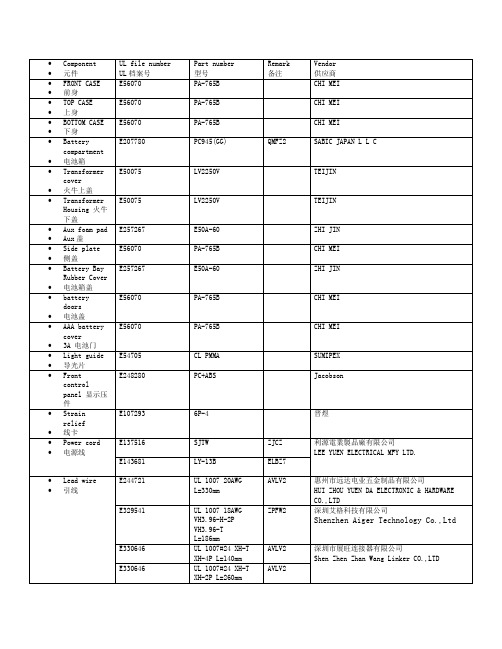
•Component •元件UL file numberUL档案号Part number型号Remark备注Vendor供应商•FRONT CASE•前身E56070 PA-765B CHI MEI•TOP CASE•上身E56070 PA-765B CHI MEI•BOTTOM CASE•下身E56070 PA-765B CHI MEI•Batterycompartment•电池箱E207780 PC945(GG) QMFZ2 SABIC JAPAN L L C•Transformercover•火牛上盖E50075 LV2250V TEIJIN•TransformerHousing 火牛下盖E50075 LV2250V TEIJIN•Aux foam pad•Aux盖E257267 E50A-60 ZHI JIN•Side plate•侧盖E56070 PA-765B CHI MEI•Battery BayRubber Cover•电池箱盖E257267 E50A-60 ZHI JIN•batterydoors•电池盖E56070 PA-765B CHI MEI•AAA batterycover•3A 电池门E56070 PA-765B CHI MEI•Light guide•导光片E54705 CL PMMA SUMIPEX•Frontcontrolpanel 显示压件E248280 PC+ABS Jacobson•Strainrelief•线卡E107293 6P-4 晋煜•Power cord •电源线E137516 SJTW ZJCZ 利源電業製品廠有限公司LEE YUEN ELECTRICAL MFY LTD. E143681 LY-13B ELBZ7•Lead wire •引线E244721 UL 1007 20AWGL=330mmAVLV2 惠州市远达电业五金制品有限公司HUI ZHOU YUEN DA ELECTRONIC & HARDWARECO.,LTDE329541 UL 1007 18AWGVH3.96-H-2PVH3.96-TL=186mmZPFW2 深圳艾格科技有限公司Shenzhen Aiger Technology Co.,LtdE330646 UL 1007#24 XH-TXH-4P L=140mmAVLV2 深圳市展旺连接器有限公司Shen Zhen Zhan Wang Linker CO.,LTDE330646 UL 1007#24 XH-TXH-2P L=260mmAVLV2E330646 UL 2547#28 PH-TPH-3P L=260mmAVLV2E330646 UL 2547#28 PH-TPH-3P L=220mmAVLV2E330646 UL 1185 22AWG XH-T XH-2P L=150mmAVLV2•Integralfuse •保险丝E340427 SFC0800A(800mA/250V FastActing Glass TubeFuse)JDYX 瑞卓电子(东莞)有限公司Dongguan Reomax Electronics Co., LTD•Fuse Holder •保险丝座E239034 H3(10A/250V)IZLT2 惠州市海牛電子有限公司HUIZHOU HINEW ELECTRIC APPLIANCE CO.,LTD.变压器材料清單/ MATERIAL LISTNO. MATERIAL DESCRIPTION Ul file MANUFACTURERS / SUPPLIERS1. 膠芯/Bobbin 最小0.71mm厚尼龍66 101(r9)一層minimum 0.71mm thick PA66101(r9) one layerUL:E41938 杜邦/E I Dupont De Nemours & Co Inc2 膠套/Shroud 最小0.50mm厚尼龍66 101(r9)一層minimum 0.50mm thick PA66101(r9) one layerUL:E41938 杜邦/E I Dupont De Nemours & Co Inc3 初級線圈PrimaryWinding 聚氨酯漆包線MW75C(130℃) 或Polyurethane Wire,MW75C(130℃)UL:E258125 河源天裕電子塑膠有限公司He Yuan Sky Wealth Electronic And PlasticCo Ltd.4 初級跨線絕緣Pri. windingcrossoverinsulation CT25聚脂膠紙/CT-25 Polyestertape厚度:0.05mm*2 層/Thickness:0.05mm*2 layersUL:E165111 靖江亞華壓敏黏膠有限公司Jingjiang Yahua Pressure Sensitive Glue COLTD5 溫度保險Thermal Fuse Type: A4-F130 Deg.C ( 250V/2A)UL:E140847 雅寶電子有限公司/Aupo Electronics Inc.6 初級引線Primary Leads UL-1672 AWG #22 VW-1 300V105Deg.CUL:E191230UL:E189674UL:E211048UL:E214859恒輝(香港)發展有限公司Ever Bright (Hongkong) development CompanyLimited.深圳东聚Shenzhen Dong Ju Wire & CableCo.,Ltd.琦富瑞Qifurui Electronics co阳泰氟电线电缆YANGTAI WIRE & CABLE CO LTD7 初級引線Primary Leads 聚氨酯漆包線MW75C(130℃) 或Polyurethane Wire,MW75C(130℃)or聚氨酯漆包線MW79C(155℃)Polyurethane Wire,MW79C(155℃)UL:E258125UL:E201757河源天裕電子塑膠有限公司He Yuan Sky Wealth Electronic And PlasticCo Ltd.太平洋電線電纜深圳公司Pacific ElectricWire&Cable(shenzhen)Co.,Ltd.8 次級引線SecondaryLeads UL-1015 AWG #20 VW-1 600V105Deg.CUL:E191230UL:E189674UL:E211048UL:E214859恒輝(香港)發展有限公司Ever Bright(Hongkong) development Company Limited.深圳东聚Shenzhen Dong Ju Wire & CableCo.,Ltd.琦富瑞Qifurui Electronics co阳泰氟电线电缆YANGTAI WIRE & CABLE CO LTD9 次級引線SecondaryLeads CT25聚脂膠紙/CT-25 Polyestertape厚度:0.05mm*3 層/UL:E165111 靖江亞華壓敏黏膠有限公司Jingjiang Yahua Pressure Sensitive Glue COLTD.Thickness:0.05mm*3 layers聚酯膠片型號:MYLAR EL21 0.25mm厚PET film Type:MYLAR EL21 0.25mmThickUL:E93687 杜邦帝人/ Dupont Teijin Films U S L P10 外層絕緣Outinsulation CT25聚脂膠紙/CT-25 Polyestertape厚度:0.05mm*3 層/Thickness:0.05mm*3 layers聚酯膠片型號:MYLAR EL21 0.25mm厚PET film Type:MYLAR EL21 0.25mmThickUL:E165111UL:E93687靖江亞華壓敏黏膠有限公司Jingjiang Yahua Pressure Sensitive Glue COLTD.杜邦帝人/ Dupont Teijin Films U S L P11 鐵芯片LaminationCore EI-57 硅鋼片(H18 黑) 片厚0.50,疊厚35.3+/-0.5mmEI-57 silicon steel sheet(H18black), thickness:0.50mm,depth thickness:35.3+/-0.5mmN/A 東莞東駿電器有限公司Dongguan Dongjun Electrical Appliances Co.,Ltd.12 安裝架/Bracket 冷軋板鍍鋅Cold rolled Steel with Zinc-coatedN/A 東莞駿豐五金製品廠Dongguan JunFeng MetalManufactory13 屏蔽殼/Endbell 冷軋板鍍鋅Cold rolled Steel with Zinc-coatedN/A 東莞駿豐五金製品廠Dongguan JunFeng MetalManufactory14 次級連接器Secondaryconnector Housing: JS-1121-02 & Terminal:JS-1121-THousing: A3963H-2P & Terminal:A3963-TPUL: E113875UL: E326732喬訊電子有限公司Chyao shiunn electronicIndustrial Ltd.長江連接器有限公司ChangJiang Connectors CoLtd15 浸漬/Impregnation Insulating Varnish/絕緣油Type: 8562/C, class FUL:E200154 恒昌化學塗料公司HANG CHEUNG PETROCHEMICALLTD。
宝贝描述(Product description)产品参数:尺寸:7英寸16:10比例,超薄薄至9.5mm屏幕:1280*800分辨率,IPS五点电容屏CPU:MTK8389 A9四核,1.2GHZ主频GPU:采用双核PowerVR SGX531内存:1G DDR3FLASH:8GB 储存容量操作系统:安卓4.1操作系统,支持人脸识别功能双摄像头:前置130万像素,后置200万像素(500万可选)3G:支持3G通话及3G上网,默认4+1,支持4+2,4+3GPS:支持GPS/AGPS/YGPA蓝牙:4.0支持FM/ATV功能电池:3000mah锂电池,可续航4-6小时电流电压:5V/2A,usb 、(HIDM可选)接口Product parameter:Size: 7 inch 16:10 ratio, Ultra thin 9.5 mmScreen: 1280*800 resolution, IPSfive capacitance screenCPU: MTK8377 A9 Four nuclear , 1.2G HZ frequencyGPU: A dual-core PowerVR SGX531Memory: 1G DDR3FLASH:8GB storage capacityOperating system: Android 4.1 operating system, support for face recognition functionDual cameras: front 1.3mp pixels,The rear 2.0mp pixels (5 million optional) 3G: Phone support 3 g and 3 g Internet access, the default 4 + 1, 4 + 2, 4 + 3 GPS: Support GPS/AGPS/YGPABluetooth:4.0Support FM/ATV functionBattery: lithium battery 3000mAh, lasts up to 5-7 hoursCurrent and voltage: 5V/2A, USB 、(HIDM optional)interface外形介绍:按键:电源键、音量键、HOME键接口:usb、耳机孔、TF卡槽、GSM卡槽、WCMDA卡槽等等七大接口。
LAM-N760,N760SP_ENG7inch Wide TFT colorTV System/Mobile Monitor OWNER’S MANUALLAM-N760SP/N760Before connecting, operating or adjusting thisproduct, please read this instruction bookletcarefully and completely.Main features7-8 Installation9-14 Parts supplied . . . . . . . . . . . . . . . . . . . . . . . . . . . . . . .9 Before installing . . . . . . . . . . . . . . . . . . . . . . . . . . . . .9 Installation order for the stand . . . . . . . . . . . . . . . . . .10 Treatment of monitor cable . . . . . . . . . . . . . . . . . . . .11 Installation of monitor unit . . . . . . . . . . . . . . . . . . .11-12 Installation order for the stand (Rear seat monitor) . . .13 Connection of exterior units . . . . . . . . . . . . . . . . . . . .14 Parts name15-17 Front view . . . . . . . . . . . . . . . . . . . . . . . . . . . . . . . . .15 Rear view . . . . . . . . . . . . . . . . . . . . . . . . . . . . . . . . .16 Remote control . . . . . . . . . . . . . . . . . . . . . . . . . . . . .17 Battery installation . . . . . . . . . . . . . . . . . . . . . . . . . . .17 Operation18-21 Power ON/OFF . . . . . . . . . . . . . . . . . . . . . . . . . . . . .18 Mode conversion . . . . . . . . . . . . . . . . . . . . . . . . . . . .18 Adjusting the volume . . . . . . . . . . . . . . . . . . . . . . . . .18 Mute . . . . . . . . . . . . . . . . . . . . . . . . . . . . . . . . . . . . .18 To enter the PICTURE menu . . . . . . . . . . . . . . . . . . .19 Adjusting PICTURE menu . . . . . . . . . . . . . . . . . . . . .19 To enter the TUNING menu . . . . . . . . . . . . . . . . . . . .19 Adjusting TUNING menu . . . . . . . . . . . . . . . . . . . . . .19 AUTO MEMORY . . . . . . . . . . . . . . . . . . . . . . . . . . . .20 SOUND SYSTEM . . . . . . . . . . . . . . . . . . . . . . . . . . .20 ADD/ERASE . . . . . . . . . . . . . . . . . . . . . . . . . . . . . . .20 FINE TUNE . . . . . . . . . . . . . . . . . . . . . . . . . . . . . . . .21 ALL RESET . . . . . . . . . . . . . . . . . . . . . . . . . . . . . . . .21 Troubleshooting22-23 Specifications242The lightning flash with arrowhead symbol, within an equilateral triangle is intended to alert the user about the presence of uninsulated dangerous voltage within the product’s enclosure that may be of sufficient magnitude to constitute a risk of electric shock. The exclamation point within an equilateral triangle is intended toalert the user to the presence of important operating and maintenance (servicing) instructions in the literature accompanying the appliance.To prevent a user or others from any physical or financial damage, please abide by the following. The following indications describe thedegree of danger or damage for the misusage.Warning“Warns the possibility of heavy injury or death.”Notice“likely to be injured or damaged physically.”Prohibition“Must not”Compulsion“Do it necessarily.”3NoteTV functions only for LAM-N760SPNoteTV functions only for LAM-N760SP5Disposal of your old appliance1. When this crossed-out wheeled bin symbol is attached to a product,it means the product is covered by the European Directive 2002/96/EC. 2. All electrical and electronic products should be disposed of separately fromthe municipal waste stream via designated collection facilities appointed by the government or the local authorities.3. The correct disposal of your old appliance will help prevent potentialnegative consequences for the environment and human health.4. For more detailed information about disposal of your old appliance, pleasecontact your city office, waste disposal service or the shop where you purchased the product.This product has been manufactured to comply with the radio interferencerequirements of EEC DIRECTIVE 89/336/EEC, 93/68/EEC and 73/23/EEC.7NoteTV functions only for LAM-N760SP.89At low temperature (20°C… or less) Turn on the heater for a proper temperature.(to enhance adhesive power).At high humidity (fog, rain and so on)After making adhesive side dried with a dryer,install the unit.After installing of the StandPulling the Monitor stand or installing the Monitor within 24 hours of the stand installation mayweaken adhesive power of the stand.Before installingAV Cable Earphone Cigar light adapter Remote Control Section-mount cradle (Rear)Section-mount cradle(Front)101112NoteRefer to your car’s user guide.A14NoteTV functions only for LAM-N760SP .When the AV Cable is insert and pulled out of the AV jack, the picture will flicker for a short moment, which is normal.15161.Left/ Right Speakers Antenna (This functions only for LAM-N760SP .)3.Docking connectorNoteActual player may vary slightly from images shown.171.Remove the battery holder with a pencil orball point pen.2.Install the battery on the battery holder.3.Install the battery holder back into its originalposition.Notes•Use only one CR2025 (3V) lithium battery.•Remove the battery if the remote control is not used for a long period of time.•Do not leave the product in a hot or humid place.•Do not handle the battery with metallic tools.•Do not store the battery with metallic materials.•In the event of battery leakage, wipe the remote control completely clean and install a new battery.Battery installationNoteWhen power of the main system is turned on or off, the picture sometimes flicker, which is normal.Notes•If power is supplied to the main system, the TV memorizes the previous status and makesNoteWhen you turn the unit off, the current volume level is automatically memorized.2. PressNoteWhen you press the AV1/AV2 switch, the pic-ture will flicker for seconds, which is normal.NoteWhen the DISPLYand 4:3, the picture will flicker for a second, ArrayTV functions only for LAM-N760SP.19202122service center in this manual and we will take a proper action. (As this product is assembled in delicate parts, only a skilled technician is recommended for the disassembly of product.)Small red, blue and green points display on the screen.•LCD screen is made in a high technology. So, this may happen due to lack of pixels by 0.001% or frequent lighting up of pixels. But, it is not the reason of any trouble.Audio and Video do not work.•Check if the starting switch of a car is on ACC or ON.•Check whether a connection code is unstable or is disconnected. •This does not work while driving.Video works but Audio does not.•Check with a volume controller if the volume level is proper.•Check whether an output port for voice is connected.The corner of the screen displays on TV.•If LCD screen has been used for long dark hours, it becomes dark gradually.•If it gets dark severely, replace its exclusive fluorescent tube.Voice quality is bad while receiving TV signal.•Change the frequency in case of interference from a radio displays only in black.•Check its color by adjusting Color Set on Menu.Note TV functions only for LAM-N760SP .bad.It noises.It noises.It noises.23P/NO : MFL3175340524。