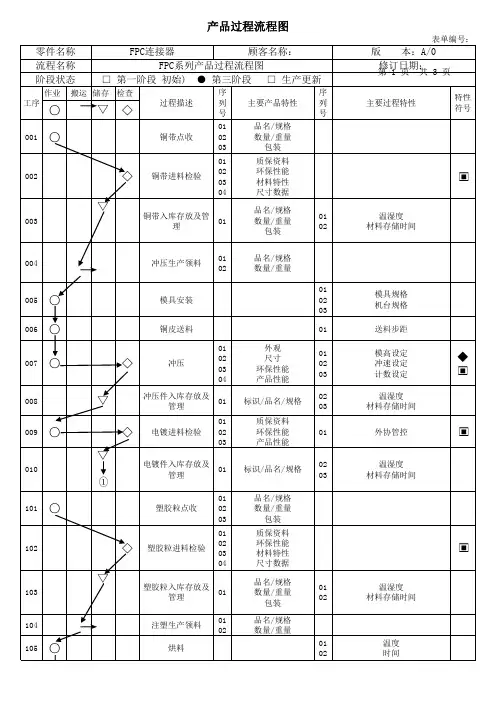
过程流程图(PFC)模板及例子
- 格式:xls
- 大小:101.00 KB
- 文档页数:86
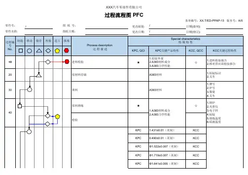
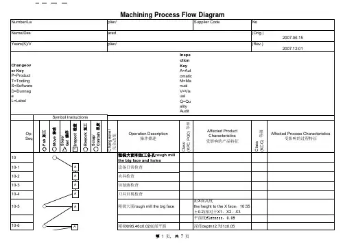
更改级别:/日期(最初):更改日期:/日期(修订):图纸日期:零件号:零件名称:图 纸 号:/过程流程图 PFC表单编号:XX.T/ED-PPAP-13 版本号:A/0XXX 汽车零部件有限公司更改级别:/日期(最初):更改日期:/日期(修订):图纸日期:零件号:零件名称:图 纸 号:/更改级别:/日期(最初):更改日期:/日期(修订):图纸日期:零件号:零件名称:图 纸 号:/KPC2X11.72±0.02(英制)KCCKPC1.25±0.02(英制)KCCKPC 2.38±0.02(英制)KCC KPC 1.56±0.02(英制)KCC KPC 2.44±0.02(英制)KCC KPC 8XΦ0.118±0.01(英制)KCC KPC KCC KPC2X45°±0.5°KCCKCC1.三轴加工中心2.刀具3.夹具4.切削液浓度检验机加工检验KPC除非另有说明,螺纹孔倒角至大径,螺纹孔内无铝屑;自攻螺套1.符合XXXX 总装图纸要求;2.符合《XX 产品总装配件清单及相关要求》3.作业后确保孔口无翻边,孔内不得有铝屑、污物等;4.无漏装、无错装、无倾斜;1.螺套规格2.工具型号3.自攻螺套作业指导书110100更改级别:/日期(最初):更改日期:/日期(修订):图纸日期:零件号:零件名称:图 纸 号:/更改级别:/日期(最初):更改日期:/日期(修订):图纸日期:零件号:零件名称:图 纸 号:/。
详解单级PFC反激电路近段时间一直忙着弄毕业论文,上论坛比较少了,前两天论文提交送审,打算发一个帖子,详细介绍一下单级PFC反激式电路结构。
单级PFC的反激式结构相信做LED电源的都不会很陌生,但估计大多数工程师做的工作限于按照IC厂商的datasheet设计产品,其中详细的原理很少有人细究。
考虑到工程应用中,复杂的公式实用价值不高,本贴将着重于定性地分析电路的工作原理,同时配合手头上能够提供的仿真和实例分析。
本帖首先介绍常用单级PFC反激式结构的几种工作模式,重点介绍一下适合用于做大功率(100W左右)的电路结构,也就是本帖实例介绍的FOT控制模式。
首先提出几个问题,希望大家能够一起探讨。
1、为什么市面上大多数单级PFC的LED驱动器都选用临界或者断续工作模式?2、为什么单级PFC的PF值随输入电压升高下降?3、为什么单级PFC的输出纹波如此之大?为了回答上面的几个问题,首先有必要讲一下单级PFC的基本原理。
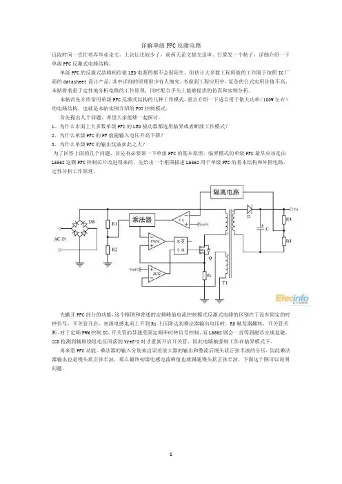
临界模式的单级PFC最早应该是由L6562这颗PFC控制芯片改进得来的,先给出一个框图描述L6562用于单级PFC的基本结构和外围电路,定性分析工作原理。
先撇开PFC部分的功能,这个框图和普通的定频峰值电流控制模式反激式电路的区别在于没有固定的时钟信号,开关管开启,初级电感电流上升到Rs上压降达到乘法器输出电压时,RS触发器翻转,开关管关断。
对于定频PWM控制IC,开关管的导通受固定频率时钟信号控制,而L6562则会一直等到磁芯完成退磁,ZCD检测到辅助绕组电压回落到Vref-2时才重新开启开关管,因此电路被强制工作在临界模式下。
再来看PFC功能。
乘法器的输入分别来自误差放大器的输出和整流后馒头状正弦半波的分压,因此乘法器输出也是馒头状正弦半波,那么最终初级电感电流峰值也就跟随馒头状正弦半波,下面这个图可以说明问题。
这个图中可以得到很多信息,首先是,跟随线电压半波的是初级电感峰值电流,而输入平均电流和初级电感峰值电流的关系为Iin-avg=Ipk*D/2,由于D是一个随线电压瞬时值升高而降低的变量,因此输入电感的平均电流较标准正弦半波而言要更加扁,功率因素不可能达到理想的1。

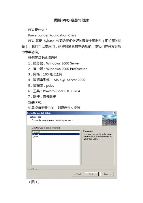
图解PFC-安装与创建PFC是什么?Powerbuilder Foundation ClassPFC就是Sybase公司给我们做好的混凝土预制件(即扩展的对象),我们可以拿来用,这些对象具有新的功能,使我们在开发过程中事半功倍。
样例在以下环境通过:1.服务器:Windows 2000 Server2.客户端:Windows 2000 Professtion3.网络:100兆以太网4.数据库系统: MS SQL Server 20005.数据库:pubs6.工具:Powerbuilder 8.0.3 97047.联接:直接联接安装PFC:如果没有安装PFC,则要自定义安装(图1)(图2)如图1,图2的高亮度选择,将PFC安装到系统中。
(图3)这样将会在系统的安装路径下面看到PFC文件夹。
如图3在PFC文件夹里面有11个.pbl文件,我们将用到其中的10个文件,pfcapp.pbl不用。
如表一pfcapsrv.pblpfcdwsrv.pblpfcmain.pblpfcutil.pblpfcwnsrv.pblpfepsrv.pblpfedwsrv.pblpfemain.pblpfeutil.pblpfewnsrv.pbl为了使用方便,可以将这10个文件拷贝到待开发的程序文件夹下面。
例如:D:\study其中的5个PFC开头的文件是PFC的基础层类库,而PFE开头的5个文件是PFC的扩展层,PFE文件在使用中不是必需的,但是考虑到今后的升级,强烈建议使用PFE文件,如果需要对PFC进行扩展或对属性进行修改,也要在PFE文件库中进行。
搭建PFC应用程序框架:(图4)我们从一个实际应用开始详细的介绍PFC程序的开发,首先我们建立一个工作空间(workspace),名字叫study。
如图4(图5)建立一个目标名为study,选中第二项,即模板项。
如图5(图6)(图7)(图8)(图9)这里是关键,一定要选择第三项。
在制造和工业应用中,色带搅拌器经常被使用。
混合器有一个中心轴,搅拌叶片的角度不同。
这些看起来像金属丝缠绕在轴上。
几何图形可以同时在不同的方向移动部分混合物,确保所有的配料都混合在一起。
离散元法非常适合这种应用。
用PFC3D对一个带式搅拌器进行建模,并使用三种粒子进行模拟:球、团块和球团(后者允许在混合过程中模拟颗粒断裂)。
球模拟的文件列表:#######几何导入命令用于导入容器的几何形状、轴和搅拌叶片。
该命令允许直接使用CAD文件(。
dxf和.stl格式被支持)在模型中包括与粒子相互作用的复杂形状的元素。
文件importBlenderGeometry。
p3dat显示了命令的使用。
使用墙壁导入几何命令,为每个导入的几何图形生成面墙。
由这些操作发出的blender结构如图1所示。
然后在墙位置定义的边界内生成一个球的集合(见球分布命令)。
由于搅拌器结构的复杂几何结构,颗粒主要产生于一个超出部分区域模型边界的盒子里。
然后,每一个球的位置都被重新访问,当粒子被发现在模型极限外占据一个区域时,粒子本身就会被删除。
这是用blender和inBody的功能完成的,它控制了每个粒子是否在模型边界之外,或者它是否与搅拌机的刀片相交。
鱼功能墙。
内部和范围FISH命令用于完成这些操作。
前者检查粒子是否落在墙内;后者允许自动检测被删除的粒子,根据在blender和inBody中指定的标准。
最后,允许粒子在搅拌器内沉淀,模拟就可以开始了。
对墙体进行了旋转速度的定义,根据其初始位置对四组球进行分组,以评价模拟过程中混合效率和效果(见图2)。
所有的命令都列在文件BlenderBalls.p3dat中。
混合效率可以从定性的角度进行评价。
在多次旋转叶片后,我们观察到混合四个初始组的结果。
图3显示了几次叶片旋转后的模拟画面。
块模拟的文件列表:BlenderClumps。
p3dat,importBlenderGeometry.p3dat类似的模拟可以用非球形的粒子来完成,使用的是clump逻辑。
(完整word版)PFC3D建模流程和代码解释本示例表示生成球体在一定的空间内进行运动的部分代码以及代码表示意义。
新建一个PFC3D模型必要部分生成的整体日志。
PFC3D 建模需要的部分和代码解释*********************************************** Logging started at 周三八月30 16:50:55 2017* By pfc3d Version 5.00 Release 025*** Job Title: Pandect example**********************************************pfc3d>pfc3d>; 3-设置模型名称,可有可无。
pfc3d>title 'Pandect example'pfc3d>pfc3d>; 4-设定计算区域(必要条件)pfc3d>; Set the domain extentpfc3d>domain extent -10.0 10.0 -20 20 ; domain当中有两个关键词是condition和extent,condition指的是边界条件periodic ;destroy ;stop ;reflect;condition默认值是stop。
extent指的是模型区域pfc3d>pfc3d>; 5-指定随机种子(若不指定,种子随机)pfc3d>set random 10001;默认值是一万,且数量级是相同的数量级,也就是该随机数值10000不能过大,不能过小。
设置随机种子以后,生成的颗粒的半径和位置都在范围内随机。
pfc3d>pfc3d>; 6-生成及修改模型组件(必要条件),有三种命令是来生成颗粒的,generate,create,distribute。
pfc3d>; Generate 30 balls in a box,wall就是一个生成颗粒的容器。
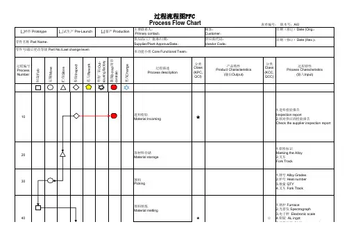
过程流程图(PFC)模板及例⼦PROCESS FLOW DIAGRAMDate (Orig.)Prepared byDate (Rev.)TitleIndustral EngineerPage Phone NumberCross Functional Team MembersStep #Fab Move Store Insp Operation description Item #1原材料发运 Raw material delivery Note2卸下原材料到检验区unload raw material to quarantine area3原材料检验raw material quarantine4原材料储存store material in rack5运送⾄开线压接区/预装区/总装车间move materials to reserve area in C/A;L/P;F/A6开线压接cut lead production and crimp7放置待检⼩车put on the cart for checking leads8检验inspect cut lead(with terminal) bundle9捆扎,挂在架⼦上 wrap and move cut lead to rack10储存在架⼦上store cut lead in rack11导线运送⾄预装压接区/总装 move cut lead to L/P and F/A .12预装压接Lead prepare13检验预装压接半成品 inspect the L/P products14放⼊储存架put into the store rack15储存storage16半成品导线运送⾄总装⽣产区域move L/P product to final assembly area 17总装及电测试final assemble the harness & electric test 18尺⼨及⽬测检验 dimension and attribute inspectionSpecial Characteristic AAFamily namePart NumberPart NameSymbol Key :Manufacturing/AssemblyMovement of Materials/PartsStorage of Material/PartsInspection171255,1117。
动力电池pfc模切工艺流程下载温馨提示:该文档是我店铺精心编制而成,希望大家下载以后,能够帮助大家解决实际的问题。
文档下载后可定制随意修改,请根据实际需要进行相应的调整和使用,谢谢!并且,本店铺为大家提供各种各样类型的实用资料,如教育随笔、日记赏析、句子摘抄、古诗大全、经典美文、话题作文、工作总结、词语解析、文案摘录、其他资料等等,如想了解不同资料格式和写法,敬请关注!Download tips: This document is carefully compiled by theeditor. I hope that after you download them,they can help yousolve practical problems. The document can be customized andmodified after downloading,please adjust and use it according toactual needs, thank you!In addition, our shop provides you with various types ofpractical materials,such as educational essays, diaryappreciation,sentence excerpts,ancient poems,classic articles,topic composition,work summary,word parsing,copy excerpts,other materials and so on,want to know different data formats andwriting methods,please pay attention!**[动力电池 PFC 模切工艺流程]**一、准备工作阶段在进行动力电池 PFC 模切之前,需要进行一系列准备工作,以确保模切的顺利进行和产品质量。
动力电池pfc模切工艺流程英文回答:The PFC (Power Factor Correction) module is a crucial component in power electronics systems, particularly in power supply units for electric vehicles. It helps to improve the power factor and efficiency of the system by reducing the harmonic content and reactive power. In this response, I will outline the typical process flow for manufacturing a PFC module for automotive applications.1. Design and Development:The first step in the process is the design and development of the PFC module. This involves the selection of appropriate components, such as IGBTs (Insulated Gate Bipolar Transistors) or MOSFETs (Metal-Oxide-Semiconductor Field-Effect Transistors), capacitors, and inductors. The design should consider factors such as power rating, switching frequency, and thermal management.2. PCB Layout and Assembly:Once the design is finalized, the next step is to create the PCB (Printed Circuit Board) layout. This involves placing the components on the board and routing the necessary connections. The PCB is then fabricated, and the components are assembled onto the board using surface mount technology (SMT) or through-hole technology (THT).3. Testing and Quality Control:After assembly, the PFC module undergoes rigorous testing to ensure its functionality and reliability. This includes electrical testing, such as checking voltage and current ratings, as well as thermal testing to verify the module's performance under different operating conditions. Quality control measures are also implemented to identify and rectify any defects or inconsistencies.4. Encapsulation and Protection:To protect the PFC module from external factors such as moisture, dust, and mechanical stress, it is encapsulatedin a protective housing. This can be done using potting or conformal coating methods. The encapsulation processensures the durability and longevity of the module in harsh environments.5. Final Testing and Validation:Before the PFC module is ready for deployment, it undergoes a final round of testing and validation. This includes functional testing to verify its performance inreal-world conditions. The module is also tested for compliance with industry standards and regulations, such as safety and electromagnetic compatibility (EMC) requirements.中文回答:动力电池PFC(功率因数校正)模块是电力电子系统中的关键组件,尤其在电动汽车的电源单元中起着重要作用。
PROCESS FLOW DIAGRAM
Date (Orig.)Prepared by
Date (Rev.)Title
Industral Engineer
Page Phone Number
Cross Functional Team Members
Step #Fab Move Store Insp Operation description Item #
1原材料发运 Raw material delivery Note
2卸下原材料到检验区unload raw material to quarantine area
3原材料检验raw material quarantine
4原材料储存store material in rack
5运送至开线压接区/预装区/总装车间
move materials to reserve area in C/A;L/P;F/A
6开线压接cut lead production and crimp
7放置待检小车put on the cart for checking leads
8检验inspect cut lead(with terminal) bundle
9捆扎,挂在架子上 wrap and move cut lead to rack
10储存在架子上store cut lead in rack
11导线运送至预装压接区/总装 move cut lead to L/P and F/A .
12预装压接Lead prepare
13检验预装压接半成品 inspect the L/P products
14放入储存架put into the store rack
15储存storage
16半成品导线运送至总装生产区域move L/P product to final assembly area 17总装及电测试final assemble the harness & electric test
18尺寸及目测检验 dimension and attribute inspection
Special Characteristic A
A
Family name
Part Number
Part Name
Symbol Key :
Manufacturing/Assembly
Movement of Materials/Parts
Storage of Material/Parts
Inspection
17
12
5
5,11
17。