RevitMEP水暖电基础知识
- 格式:pptx
- 大小:6.20 MB
- 文档页数:2
R e v i t M E P基本概述教程本教程将提供有关Revit MEP 学习入门的信息,主要内容包括:概况介绍在教程中设计的建筑信息模型的基本概念和相关术语以及如何与其它相关专业开展协同设计的操作流程。
在这些教程中,用户将学习如何在Revit MEP 中创建并设计建筑信息模型(BIM)。
同时也将学习与Revit Architecture 和Revit Structure 两款兄弟产品的链接操作与协同设计。
教程的组织方式:本教程是遵循典型的机械、电气和卫浴工程的工作流。
用户将在后续的详细教程完成以下设计培训:•导入二维(DWG) 或三维(RVT) 格式的建筑楼层平面。
•添加基本MEP 图元,如风管、装置和管道。
•添加更详细的建模图元,如机械设备、配电盘和卫浴装置。
•分析系统并优化MEP 图元。
•创建明细表、视图和图纸,以创建项目施工图。
•创建详图视图、注释和标记。
教程练习的设计遵循基本和简明的原则。
用户不必设计整个系统,而只需设计足以了解本产品中各种工具和选项的使用方法的部分系统即可。
例如,添加管网时,只需在建筑的一个翼楼中绘制风管。
在打开有些培训文件时,用户会注意到文件中包含之前在练习中并未特别添加的MEP 图元。
例如,为提供更丰富且更完善的设计,在后续培训文件中并入了诸如其他管网和设备等图元。
这些图元强化了用户将完成的练习。
★了解基本概念在本课程中,将学习Revit MEP 是什么,以及如何从其参数化修改引擎功能中受益。
先从Revit MEP 所依据的基本概念入手。
用户将学习术语、图元层次结构,以及如何在产品中执行某些常见任务。
★了解概念什么是Autodesk Revit MEP?用于建筑信息模型的Revit MEP 平台是建筑设计和文档系统,它支持建筑项目所需的设计、图纸以及明细表。
建筑信息模型(BIM) 提供了用户需要的有关项目设计、范围、数量和阶段等信息。
在Revit MEP 模型中,所有的图纸、二维视图和三维视图以及明细表都是同一个基本建筑模型数据库的信息表现形式。

(Building Information Modeling ,建筑信息建模)的强大功能。
这就是未来的系统设计 - Revit MEP 2009。
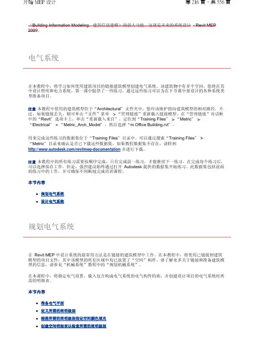
在本教程中,将学习如何使用建筑项目的链接建筑模型创建电气系统。
该建筑物中有多个空间,您将在其中设计照明和电力系统。
第一课中提供了一些练习,通过这些练习可以为在下节课中要设计的各种系统类型准备项目。
注意本教程中使用的建筑模型位于“Architectural "文件夹中。
您应该维护指向建筑模型的相对路径。
不过,如果链接丢失,则可单击“文件”菜单 “管理链接”重新载入链接模型。
在“管理链接”对话框中的“Revit "选项卡上,单击“重新载入来自”,定位到“Training Files "“Metric "“Electrical "“Metric_Arch_Model ",然后选择“m Office Building.rvt "。
用来完成这些练习的数据集位于“Training Files "目录中。
可以通过搜索“Training Files "“Metric "目录来确认是否已下载这些数据集。
如果教程数据集不存在,请转到 /revitmep-documentation 并进行下载。
注意本教程中的所有练习需要按顺序完成,只有完成前一练习,才能继续下一练习。
在完成每个练习后,可以选择保存工作。
但是,强烈建议始终通过打开 Autodesk 提供的数据集开始练习。
此数据集包括前面的练习中的工作,并可确保不间断地完成培训课程。
本节内容z 规划电气系统 z设计电气系统在 Revit MEP 中设计系统的最常用方法是在链接的建筑模型中工作。
在本教程中,将使用已链接到建筑模型的项目文件,其中该模型的所有区域中均已放置了“空间”构件。
要了解更多关于链接和准备建筑模型的信息,请参见“机械系统”教程中的“规划机械系统”。
在本课程中,将指定电气设置,载入包含构成电气系统的电气构件的族,并创建设计项目的电气系统时所需的明细表。
RveitMEP深化概述:排水、暖通、电气系统与建筑物一起构成一个有机整体,其管线的布置要与建筑物内部结构和空间分布相统一,为了更真实地表现出水暖电模型的准确性、合理性,创建与水暖电模型相应的建筑结构模型是有必要的。
在RveitMEP深化过程中基本分为2个步骤:1、建筑结构模型绘制。
2、机电综合的模型绘制。
一、建筑结构模型绘制。
1.熟悉CAD图纸现在的绘图模式很大部分采用先绘制CAD二维图纸,然后根据实际项目的需要绘制成三维图纸。
2.打开RveitMEP软件新建机械项目文件。
3.CAD图纸导入Revit MEP软件中为了利用CAD图纸中的线条进行定位,需要将CAD图纸导入Revit MEP软件中作为底图。
各系统分类的图纸,画该系统时分别导入,或一次性在CAD整合,以一张完整的图纸导入,省去重复导入工作。
4. 创建轴网创建建筑结构模型之前,需要确定模型主体之间的定位关系。
其定位主要通过标高和轴网的建立来实现创建轴网,根据导入的CAD地图的轴网为基准,通过初始的设置后采用约束复制发,画完轴网,并防止不小心移位我们采用锁定工具。
5. 创建标高根据图纸设定所需要的标高,进入立面视图设置标高数值并分层设置出各层标高平面。
6.创建结构柱首先载入矩形结构柱,根据结构图,识别柱子大小,在“图元属性中通过复制命令更改创建不同大小的结构柱。
如新建结构柱名称“600×600”,在类型属性中的“尺寸标注”栏中将b、h值均改为600,单击“确定”,完成结构柱的创建更改完成后,进入结构柱最底层的平面图,根据基准底图,逐个绘制结构柱,并设置结构柱高度。
7.创建剪力墙与砖墙更改墙的材质来区别墙体构造,字图元属性中,在结构中挑选材质。
在弹出的―放置墙‖选项卡中的―绘制‖面板中选择―直线‖命令,鼠标左键单击确定墙体的起点,再一次单击确定墙体的终点,沿顺时针方向绘制墙体。
也可用―绘制‖面板中的―拾取线‖命令,定位线选择―面层面:内部‖,拾取CAD图中的墙体边线,创建墙体。


Everything Electrical for Revit MEP®Don Sarmiento – ARUP, Senior CAD Technician [San Francisco, CA]Geoff Gunn, PE – ARUP, Senior Engineer [Boston, MA]MP6679The title of this class speaks for itself. You will learn everything you need to know about Revit MEP software, focusing entirely on the electrical side. Topics will include managing your project template; creating 2D annotation symbols and electrical families; creating more efficient diagrams; using filters for your electrical systems; and laying out fixtures. We’ll also look at devices and equipment, circuiting, and scheduling. We will cover techniques for achieving better coordination between disciplines (mechanical, electrical, and plumbing) and making the most out of Revit MEP software and we will discuss some best practices. We will also share with you an actual project that implemented items discussed during this lecture.Learning ObjectivesAt the end of this class, you will be able to:•Learn different techniques for efficient diagrams and discover why it's better in Revit software, forget linked CAD files•Learn how to create efficient 2D annotations and electrical families and discover that it's not always about how they look, but how they work•Using filters for better workflow. You'll be surprise what filters can do for you•Learn about coordination practices between electrical and mechanical, plumbing, and lighting, and discuss how we should we handle thisAbout the SpeakersDon Sarmiento is a Senior CAD Technician at Arup, a multidiscipline engineering firm based in San Francisco, California, which has over 90 offices throughout the world. He has over 17 years of experience in electrical drafting, using AutoCAD® software, AutoCAD MEP® software, and Revit MEP® software. He also worked as an electrical designer for over 5 years. Currently he is involved in the implementation of Building Information Modeling (BIM) using Revit MEP® software for the Electrical Group within Arup’s America’s region. He also provides internal training of Revit software and often presents at internal and regional meetings.**********************Geoff Gunn is a Senior Electrical Engineer based in the Boston, Massachusetts office of Arup, a multidiscipline engineering firm which has over 90 offices throughout the world. He has experience in electrical engineering for a wide range of project types from University labs, healthcare facilities, and data centers. Geoff has detailed hands-on experience producing electrical engineering designs using AutoCAD® software, AutoCAD MEP® software, and Revit MEP® software. Geoff is always looking for new ways to introduce Building Information Modeling techniques into the electrical engineering process in order to simplify drawing production, improve accuracy, and enhance communication with Architect's and facility Owners.*******************Techniques for Efficient Diagrams in RevitLet’s be honest. When we all transitioned from AutoCAD to Revit, the last thing that we probably did in Revit, was our diagrams and our details. Maybe because we were intimidated by change, and just not familiar with the commands in Revit. But working in a 2D environment in Revit is actually really easy and efficient, and it is just a matter of getting used to it.Here are some tips on how to create efficient diagrams in Revit.1. Create all your contentIf it’s a symbol, create it! Consider using masking region in building your symbols. We’ll discuss more about this later.2. Determine your sheet limitsThis should be the first thing you ever do when drafting. You don’t want to keep drafting then realize you’ve drawn over your sheets as you finish. Check your border, and measure.3. Create a grid guide in your drafting view or floor plan that matches your sheet limitsCreating a grid allows you work quicker, more efficient, and prevents you from “eye balling”, when laying out your detail lines. This will also allow you to create a more presentable diagram. Creating a family would make this more efficient.4. Pin the grid guideDetail item family5.Click on the “Select Pinned Elements” iconBy pinning the grid, then clicking on the “Select Pinned Elements” icon, this will allow you to hover over the grid, without selecting the grid. After these simple steps, you should be able to start on your diagram.6.Create different line styles for each distribution branchThis allows for your too easily follow the connections.7.Utilize the grid guide lines when drafting your detail lines8.Consider using masking region, instead of splitting when lines intersect as belowHere are the steps in using masking region:a.Create a masking region.b.Highlight the details lines that you do not want masked, then “bring to front”.The image below is the result after masking.9.Lock generic annotations (symbols) onto the detail linesThis allows the symbols to move with the detail lines as it moves.10.Turn off the grid guide before you printTip: If your diagram is large enough to continue onto another sheet, you can also create your diagram in a floor plan so you could generate dependent views.Figure 1.1 below is one of the most complex diagrams that I have ever worked on, created in a floor plan view, duplicated into 3 dependent views (Figure 1.2). Remember, all lines runs across continuously from sheet to sheet like the levels, and feeders. Lines are masked between sheets using masking region.Figure 1.1Figure 1.2Efficient 2D Symbols and Modeled familiesCreating content could be lots of fun. Once you get into it, you will think of different ways to be creative with your content, and try to make them as efficient as possible. Here are some things to consider when building content.1. For 2D Generic Annotation Familiesa.Make good use of masking region.b. Create all the Labels and Text as needed. If it needs to change, use a Label and set it asan instance. If not, use a Text. Name the Label to be understandable.c. Visibility. If there are multiple Symbols in your Family, make sure to set the visibilitycorrectly with a Yes/No Parameter.Masking regionMasks the detail line as you place your symbolLabel TextFilled region controlled by yes/no parameter “GFCI”Filled region controlled by yes/no parameter “Emergency”2.For Modeled Familiesa.Keep the 3D modeling simple. There is no need to show the nuts and bolts, every curveand angle of the device/fixture/equipment. As long as you show the overall dimensions,then that should be enough for coordination.b.Family Category and Parameters. Make sure these are set correctly. Check theOmniClass Number as well.c.Family Types. Do not use the Family Name in the Family Type Name. Name them toshow the size or information specific to the Family Type.d.Scheduling. If the Family is to be scheduled in Revit, make sure you have all necessaryShared Parameters set by your firm.e. Annotation Symbols. Families like electrical, ITC, fire alarm, lighting devices, some lightfixtures like downlights, exit signs, do require Annotation Symbols. If the family uses the size of the model as its symbol, like 2x4 light fixtures, then use a Detail Item.• Nest the Annotation Symbol/Detail Item families.• Make sure Symbols are per your company standards.• Visibility. Determine if the Symbol(s) requires a Visibility option to display theSymbol or not and set the visibility correctly with a Yes/No Parameter.• Set the Symbol(s) “Visibility/Graphics Overrides” to show only in Coarse andMedium Detail Level.f. Name your Reference Planes/Lines correctly such as Front, Back, Center (Front/Back),etc. This will allow for users to figure out how the content was built, and allow for easy modifications to the family when required.g. Set Dimensions to Reference Planes/Lines, not Detail Lines or Modeled Elements.h. If an equipment requires a clearance, show it. This would help in the design process. Youcan base the clearance per code, or from the manufacturer.PanelClearancei.Nest the different Components of the family, like the equipment, clearance, pads. TheseNested Families can be created as Generic Models. This makes your family free of multiple reference planes, and makes each component easier to manage within the family.j.Electrical Connectors. Make sure that correct parameters are linked to the Connector Element. For conduit connectors, make sure they are facing the right direction.k.Test your Family. When the family is loaded into a project, does it do the necessary changes in size, movements and visibilities without errors? Make sure to test allparameters that are shown in the properties of the Family.Figure 2.1 is an example of our Switchboard Family3D View Plan ViewSwitchboardSwitchboard Placeholder Detail Item or Annotation SymbolPad Equipment ClearanceFigure 2.1Using Filters for Electrical Distribution BranchIn this objective, we would like to share how we’ve used filters as a design tool by color coding the different electrical distribution branches. This is just one example of the countless possibilities where in you could use filters, and shows how powerful this is.1.Items to consider when creating filtersa.Filter naming. Use a standard naming convention, and have this figured out before youstart.b.Filter rules. Determine the necessary parameters you need for each filter.c.Visibility, Projection/Surface. How do you want represent these in your view? Determinethese as well.d.Be creative2.How to set-up your filtersa.Go to visibility graphics, then under the Filters tab, click on Edit/New…b.Under Filters, click on Create New, assign the Filter Name, click OK…c.Select the category you want to filter, then apply filter rules, click OK…d.Under Filters, click on Add, then under Add Filters, select the filter, click OK…e.Under Visibility Graphics, select the filter name, then override its visibility as you wish,which in this case we changed the color alone. Click OK under Color, then click OK under Line Graphics…f.Under Visibility Graphics, click OK to finish.Figure 3.1 below shows the different filters we’ve created based on the different distribution branches that we use. We created filters for equipment, and electrical devices/wires. We then matched the projection lines per the distribution branch. It is highly recommended to set these in your view templates.Figure 3.1The beauty about filters, is that visually elements change their projection lines based on the rules that you have set. We matched the electrical distribution branch filters projection lines between equipment and devices/wires, so as you circuit your device to a panel, they would match colors.Figure 3.2 below shows that as we layout our electrical equipment, they come in as a default color, white. As we named the panels (figure 3.3), they change colors based on how we name our panels. This also tells us, whether or not we have actually named our panels. The filter rule we applied here, is that an electrical equipment, is filtered by panel name, which begins with…Figure 3.2 Figure 3.3Figure 3.4 below tells us, whether or not we have circuited our device, and as you circuit (figure 3.5), the device and wire colors change to match the corresponding panels it’s assigned to. The filter rule we applied here, is that an electrical device, is filtered by panel, which begins with…Figure 3.4 Figure 3.5We also used filters for coordinating between electrical connectors and the architects/lighting designers lighting layout, and for the coordination between electrical and mechanical equipment, showing only mechanical equipment that have electrical power in our electrical plans. We will discuss more about these in the next objective.Coordination between Electrical and Other DisciplinesRevit is such a powerful software, and it’s in coordinating the different disciplines where you could take full advantage of this. Coordination between architectural and structural, structural andmechanical/plumbing, and of course, electrical and everyone else! There’s so many ways on how we can accomplish this in Revit, and we would like to share with you how we do it.1. LightingIn most cases, the architect and/or lighting designer usually models the light fixtures when you receive the architectural Revit model from them. So since it’s been modeled already, then there’s no need to redo the work. Since we cannot circuit between linked models, we decided to create light fixtures that act as connectors, which represents our symbols, for circuiting purposes only.Here’s our process:a. Create the light fixture families to match the architects and/or lighting designers scheduleand/or specs focusing on dimensions, voltage, apparent load, and wattage. Dimensions are important to match, so as you overlay the fixtures, they line up. If your are creating a schedule yourself, then incorporate all the parameters needed as well like description, lamp type, number of lamps, and tag.b. Create a coordination view or design view rather than using your sheet view. Visually, itwould be easier to coordinate the fixture locations here.``` Coordination or design viewSheet viewc. Set-up your filters in your view templates. In figure 4.1 below, we created 2 filters. Thefirst one for the architects/lighting designer’s layout, and the other one for our light fixture connector. We filtered our light fixture connector simply by family name, changed our projection patterns, and modified the transparency on either one. On the modelcategories tab, we also turned off the visibility of all models except for the light fixtures.Figure 4.1d. In the coordination view, we overlaid our light fixtures on top of theirs. Figure 4.2 belowshows that the blue fixture indicates the architect/lighting designer’s light fixture layout, and yellow fixture indicates our light fixture connectors. Gray indicates we’ve overlaid the fixtures, and that the location is coordinated.Figure 4.2Our light fixture connectorCoordinated fixture locationArchitects and/or lighting designer’s layoutUncoordinated fixture location2.Mechanical/Plumbing EquipmentIdeally, you only want to show mechanical or plumbing equipment that has power on yourelectrical plans. We used filters to control which mechanical equipment to show, by adding ayes/no parameter “is Electrical Power” to the mechanical equipment. You can also coordinateyour schedule with theirs, by creating a multi-category schedule, and comparing the mechanical equipment data, to your motor connector data.Here’s our process:a.Create a motor connector family that contains common shared parameters that also existin the mechanical equipment. These parameters will be used this to filter and sort out ourschedule, and for visibility of our mechanical equipment on our electrical plans. We alsocreated the different types of motor sizes based on voltage, phase and horsepower perNEC.Figure 4.3 shows the parameters that we are sharing between electrical and mechanicalfamilies, which are:•Is Electrical power Yes/No parameter•Equipment Type Text parameter•Equipment Number Text parameterFigure 4.3b. Set-up your filter in your view templates. In figure 4.4, we created a “Mech EquipmentPower” filter, which is filter by the “Is Electrical Power” parameter, equals “no”. In the filters tab, we then turned off the visibility. Make sure to turn on the visibility of the mechanical in the model categories tab, and change the projection lines of themechanical equipment. This will then turn off all mechanical equipment that has no electrical power in your view.Figure 4.4c. Layout your motor connector to line up with the mechanical layout. You can lock theconnector to the mechanical equipment (figure 4.5), so it moves with it. Consider tagging directly the mechanical equipment (figure 4.5), instead of your connector, so whenmechanical changes the equipment name, it updates. Update the Equipment Type and Number parameters on your connector to match the mechanical (figure 4.6).Figure 4.5Figure 4.6Tag directly the mechanical equipment Lock theconnector to the equipmentUpdate to matchmechanicald. Create a multi-category schedule for electrical mechanical coordination. We then filteredthis by the yes/no parameter “Is Electrical Power”, then sorted it out by Equipment Type, then Equipment Number, then Family. We then refer to the mechanical equipment voltage, phase and horse power, then select our family type to match.Figure 4.7Figure 4.8 shows the layout of the mechanical engineer. Figure 4.9 shows the power plans, wherein the only mechanical equipment outline shown are the (2) FCU’s, since these are motorized and are to be scheduled.Figure 4.8Figure 4.9Shared parametersShared parametersFrommechanical equipment From electrical connectorChange type to match mechanical`Everything Electrical for Revit MEP®Thank you for attending AU 2014, and for joining us in our class today. We do hope that the objectives discussed in this class will be beneficial to you.21。
Revit_MEP_基础功能Revit_MEP_基础功能Revit MEP 2022年用户手册Revit MEP 基本功能本章介绍了Revit MEP 中可通用于电气、机械、管道、卫浴和消防规程的基本功能。
本节内容zzzzzzzzzzzzz系统设置Revit MEP 管道工具放置机械设备风管和管道转换设置系统编辑工具管网和管道的选项栏设置连接到生成布局调整风管和管道的大小系统浏览器系统检查器空间内嵌明细表Revit MEP 2022年用户手册Revit MEP 基本功能系统设置项目中系统构件的外观和表现是由各个规程对应的设置确定的。
zzzzzz电气设置指定了电压、电力配电系统、配线和需求系数。
“机械设置”决定着项目中风管、管道、卫浴和消防系统管网和管道的行为和外观。
风管系统设置管道系统设置卫浴系统设置消防系统系统设置Revit MEP 2022年用户手册Revit MEP 基本功能Revit MEP 管道工具Revit MEP 提供了创建管道、卫浴和消防系统所需要的工具。
单击下列链接之一可获得特定系统类型的相关信息:zzz使用管道构件使用卫浴构件使用消防构件Revit MEP 2022年用户手册Revit MEP 基本功能放置机械设备Revit MEP 提供了为HVAC、管道、卫浴和消防系统放置机械设备所需要的工具。
单击下列链接之一可获得特定系统类型的相关信息:zzzz风管系统管道系统卫浴系统消防系统Revit MEP 2022年用户手册Revit MEP 基本功能风管和管道转换设置可以使用风管“转换设置”或“管道转换设置”对话框指定控制以下项的参数:使用“布局路径”工具时创建的管道或管网的高程、管道或风管尺寸和其他特征。
单击下列链接之一可获得特定系统类型的相关信息:zz风管转换设置管道转换设置Revit_MEP_基础功能Revit MEP 2022年用户手册Revit MEP 基本功能系统编辑工具选择某个系统后,“系统编辑工具”将可用。
快速入门本节内容z简介简介本简介可帮助您学习使用 Revit MEP 2009 教程,并提供了产品的基本概念,包括:z Revit MEP 是如何工作的。
z使用产品时所用的术语。
z如何导航用户界面。
z如何执行产品中的某些常规任务。
本节内容z使用教程z了解基本概念使用教程在本课程中,将学习如何使用 Revit MEP 教程,包括如何找到培训文件,以及如何从样板文件中新建 Revit MEP 项目。
Revit MEP 教程窗口的“内容”选项卡会显示可用的教程标题。
在教程中展开一列课程的标题。
在课程中展开一列练习的课程标题。
注意将教程打印出来会有助于您在使用 Revit MEP 时易于参考其中的说明。
也可以通过单击 Revit MEP 中的“帮助”菜单 “网上文档”获取 PDF 格式的教程。
本节内容z访问培训文件访问培训文件培训文件是专门为教程的使用而创建的 Revit MEP 项目、样板和族。
在本练习中,将学习如何找到培训文件,以及如何打开并保存培训文件。
如何找到培训文件的位置?默认情况下,培训文件位于“C:\Documents and Settings\All Users\Application Data\Autodesk\RME2009\Training"。
在“Training"文件夹中,培训文件被分为 3 个文件夹:z Common:讲授概念时经常用到的一般文件。
这些文件与英制或公制单位无关。
常规文件的名称中含有前缀 c_。
z Imperial:指为使用英制单位的用户准备的文件。
英制文件的名称中含有前缀 i_。
z Metric:指为使用公制单位的用户准备的文件。
公制文件的名称中含有前缀 m_。
注意根据安装情况的不同,培训文件夹可能位于不同的位置。
联系 CAD 管理员可获得详细信息。
重要信息可在培训文件位置找到并访问教程中所使用的内容(如样板和族)。
尽管此内容可能安装在您计算机的其他位置,但本教程中使用的所有内容都包含在培训文件位置中,以确保所有读者都能访问正确的文件。
和技术,也代表上述学科和技术所涉及到的行业和产业。
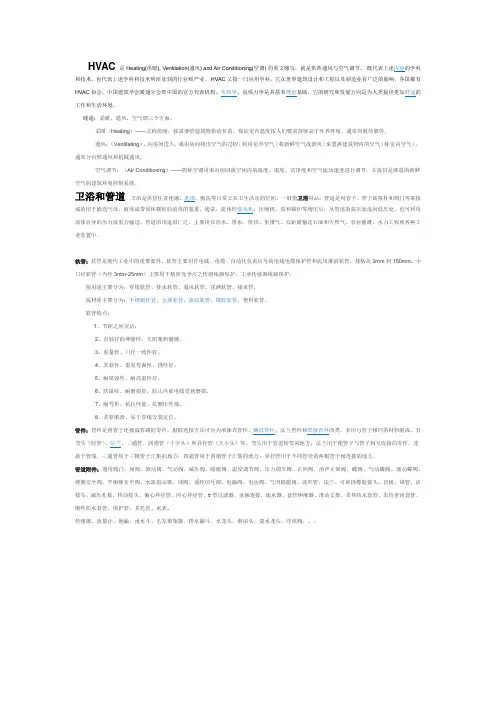
HVAC又指一门应用学科,它在世界建筑设计和工程以及制造业有广泛的影响,各国都有工作和生活环境。
暖通:采暖、通风、空气调三个方面。
采暖(Heating)——又称供暖,按需要给建筑物供给负荷,保证室内温度按人们要求持续高于外界环境。
通常用散热器等。
通风:(Ventilating),向房间送入,或由房间排出空气的过程。
利用室外空气(称新鲜空气或新风)来置换建筑物内的空气(称室内空气),通常分自然通风和机械通风。
空气调节:(Air Conditioning)——简称空调用来对房间或空间内的温度、湿度、洁净度和空气流动速度进行调节,并提供足够量的新鲜空气的建筑环境控制系统。
卫浴和管道卫浴是供居住者便溺、洗浴、盥洗等日常公共卫生活动的空间。
一般指卫浴用品;管道是用管子、管子联接件和阀门等联接流体自身的压力或重力输送。
管道的用途很广泛,主要用在给水、排水、供热、供煤气、长距离输送石油和天然气、农业灌溉、水力工程和各种工业装置中。
软管:软管是现代工业中的重要部件。
软管主要用作电线、电缆、自动化仪表信号的电线电缆保护管和民用淋浴软管,规格从3mm到150mm。
小口径软管(内径3mm-25mm)主要用于精密光学尺之传感线路保护、工业传感器线路保护。
按用途主要分为:穿线软管、排水软管、通风软管、花洒软管、线束管。
按材质主要分为:不锈钢软管、金属软管、波纹软管、橡胶软管、塑料软管。
软管特点:1、节距之间灵活;2、有较好的伸缩性,无阻塞和僵硬。
3、重量轻、口径一致性好。
4、柔软性、重复弯曲性、挠性好。
5、耐腐蚀性、耐高温性好。
6、防鼠咬、耐磨损好,防止内部电线受到磨损。
7、耐弯折、抗拉性能、抗侧压性强。
8、柔软顺滑、易于穿线安装定位。
管件:管件是将管子连接成管路的零件。
根据连接方法可分为承插式管件、螺纹管件、法兰管件和焊接管件四类。
多用与管子相同的材料制成。
有弯头(肘管)、法兰、三通管、四通管(十字头)和异径管(大小头)等。
Revit®MEP 2009Design. Analyze. Optimize.Duct and Pipe Sizing/Pressure Calculations Built-in calculators make it possible to perform sizing and pressure loss calculations according to industry-standard methods and specifications, including the American Society of Heating, Refrigerating, and Air-Conditioning Engineers (ASHRAE) fitting loss database. System sizing tools instantly update the size and design parametersof duct and pipe elements, without the need for file exchanges or third-party applications. Select a dynamic sizing method for the ductwork and piping systems in your plans using Duct Sizing and Pipe Sizing tools. Use the friction, velocity, static regain, or equal friction sizing method for duct sizing. Use the velocity or friction method for pipe sizing. Duct and Pipe System ModelingIntuitive layout tools enable easy model modifications. As always, Revit MEP software automatically updates your model views and sheets, helping to maintain document and project consistency. Create HVAC systemswith mechanical functionality providing 3D modeling for ductwork and piping. Easily modify the model by dragging design elements on the screen in almost any view. Modeling can alsobe done in both section and elevation views. All model views and sheets update automatically whenever a change is made anywhere for accurate, coordinated designs and documents at all times. HVAC/Electrical Space Design Communicate design intent visually with room color-fill plans that facilitate client validationof design reviews and criteria. All revisionsand alterations to color-fill plans are updated automatically across your model. Create any number of schemes, and maintain consistency for the duration of your project. Three-dimensional modeling for ductwork and piping enables you to create HVAC systems that can be clearly shown using customer color schemes for design airflow, actual airflow, mechanical zones, and more. Create electrical color schemes for power loads, lighting per area, and more. With color schemes, deciphering spreadsheets and using colored pencils on printed plans are no longer necessary. System Inspector (Critical Path)Quickly identify and adjust high pressure loss areas in your system, enhancing economy and efficiency. Interactively modify fittings, shape, or configuration, and instantly see the updated static pressure loss and changes to flow properties. Revit MEP software displays the critical flow path for branches, main trunks, or entire systems.Revit® MEP software is an intuitive mechanical, electrical, and plumbing system design tool, enabling enhanced coordination and rapid design within a building information model. Optimize systems engineering through data-driven system sizing and design. Use the building performance analysis tools within the Revit MEP building information modeling (BIM) software application to support sustainable design. Accelerate accurate decision making through faster engineering design data creation and more reliable client communications. Using consistent, compatible models created in Revit® Architecture orRevit® Structure software, you can minimize time-consuming errors between mechanical, electrical, and plumbing (MEP) engineers,structural engineers, and architects. Automatic change management across your evolving design and documentation set helps to keep yourplans consistent and your projects on track. Experience the BIM advantage by designing optimized engineering systems, and enhance building performance with analysis support. Enable appropriate feedback on your design’s scope, schedule, and budget.Sustainable Design SupportRevit MEP software provides integrated heating and cooling loads analysis tools to help you perform energy analysis, evaluate system loads, and produce heating and cooling load reports for a project. Provide optimal systems design with the same building information model, with realistic, real-time design scenarios aiding better decision-making support. Revit MEP helps to minimize design errors and better define your project’s overall sustainability strategy. Take full advantage ofthe data-rich Revit MEP model to support better decision making through integrated building performance analysis tools. Revit MEP also supports green building extensible markup language (gbXML), containing information for spaces and zones as well as lighting fixture element data. Export the gbXML file for use with a third-party analysis application for calculating loads. Create high-performance, sustainable buildings with extensive analysis of heating and cooling load,LEED daylighting, thermal energy, and more.Panel SchedulesAutomatically create electrical panel schedules in your designs. Balance loads or change circuits for a device through panel schedules. Easily edit the panel circuits through a built-in panel circuit editor. Panel schedules can be formatted like most Revit schedules. Benefit from multiple panel schedules and the ability to change electrical devices directly in the panel schedule.Lighting and Power CircuitryUse circuits to track loads, monitor attached devices, and verify circuit lengths. Define wire types, voltage ranges, distribution systems, and demand factors to prevent overloads and mismatched voltages. Accurately calculate the estimated demand loads on feeders and panels to size equipment quickly and efficiently. Using circuits to track loads, number of devices, and circuit lengths helps to minimize errors in the electrical design. Create high-performance, sustainable buildings with extensive analysis of heating and cooling load, LEED daylighting, thermal energy, and more.Parametric ComponentsParametric components offer open, graphical systems for design thinking and precisely detailed design intent. Use parametric components for your most elaborate mechanical, electrical, and plumbing engineering assemblies, with no need for programming languages or software coding. Construction DocumentationAutomatically generate plan, section, elevation, detail, and schedule views that precisely reflect design information. Synchronized model views from a common database enable consistent, coordinated change management. Benefit from more accurate, coordinated construction documents that BIM provides for the mechanical, electrical, and plumbing design team.Automatic Sheet Drawing ReferencesSections, elevations, and call-out references are more accurate, while all data, graphics, details, schedules, drawings, and sheets in the drawing set are current and coordinated. No longer spend hours coordinating sheet sets: Revit MEP helps automate the process with ease.System BrowserEasily perform model continuity checks on defined system types, quickly see unbalanced loads, and identify orphaned elements not connected to systems. Help to ensure that all mechanical, electrical, and plumbing system elements are connected and contributing to system loadrequirements for accurate sizing. Revit MEP software gives engineers confidence that the mechanical, electrical, and plumbing systems designs are complete.DWG/DWF/DXF/DGN SupportNative support for DWG,™ DWF,™ DXF,™ and DGN formats help ensure fully compatible data exchange. The ability to import, export, and link data with the industry-leading DWG format makes Revit MEP one of the best coordination and collaboration solutions available.Revit MEP software helps maximize theeffectiveness of leveraging your architectural and engineering BIM design and construction documentation processes. Enhance clientcommunications and accelerate decision making through in-process visualization. Smoothly collaborate with Revit Architecture and Revit Structure using a Revit model. Built on the latest version of the Revit ® platform, Revit MEP provides all the competitive advantages of BIM.Interference CheckingCoordinate major building elements and systems during design, avoiding collisions between elements and reducing the risk of construction cost overruns. Choose which building elements to check for interference, whether duct and structural beams, or lighting fixtures and diffusers. Revit MEP automatically generates a report with the ability to zoom into the area of interference for easy clash resolution.Bidirectional AssociativityA change anywhere is a change everywhere. Storing your information in a single, consistent database helps to ensure that your entire model is always up-to-date. Parametric technologyautomatically manages all change propagation and keeps your project on track. The ability to change a schedule and automatically update the modelis a key benefit of using Revit MEP software.Change is good.Parametric change is better for coordination.meet ever-growing client demands are key indicators for parametric BIM technology as the design methodology of choice overconventional methods.— T im DeRuyscher, PE Executive Vice President RobsonWoese Inc.Publish to Autodesk BuzzsawPublish to Autodesk ® Buzzsaw ® functionality enables team members to seamlessly upload Revit MEP files to a predetermined Buzzsawproject site. With the addition of default template assignments, you can assign properties to a view and set those properties back to their original state before project publication or printing.Interface to External DatabasesFacilitate communications with third-party estimating, planning, procurement, and facility management tools by outputting Revit MEP model data to any ODBC-compliant database. Import/Export ACIS Solids with AutoCAD-Based ApplicationsRevit-based products can read and write ACIS ® solids, enabling easy import and export between Revit MEP models and other AutoCAD ® software–based architectural or engineering applications. Import or link 3D solid geometry into AutoCAD ® Architecture or AutoCAD ® MEP software.Application Programming Interface (API) A rich programming environment, the Revit API facilitates and extends Revit functionality throughout the building industry.Create realistic representations of mechanical, electrical, and plumbing engineering systems,enhancing communication of your designs and those of your clients. Benefit from automated exchange of engineering design data from detailed building information models. Help identify errors earlier, and reduce the need for costly redesigns later.WorksharingRevit MEP worksharing distributes the power of the parametric modeling environment across the project team. Worksharing provides a complete range of collaboration modes, from entirely on-the-fly, simultaneous access to the shared model, through the formal division of the project into discrete shared units, to complete separation of project elements or systems into individually managed linked models. Design teams can effectively collaborate and interact based on workflow and project requirements through worksharing.RenderingBuilding designs are often presented to clients in the form of rendered, photorealistic images. Revit MEP software renders 3D project views with various effects, such as lights, plants, decals, and people. Add sunlight to an interior scene of the model for radiosity solutions. Select families with transparent materials as daylight sources. Revit MEP enables clients to see the building systems design before it is built through photorealistic images.Visualize. Communicate.Lighting CalculationsZonal cavity estimation automatically calculates room lighting levels. Set room surface reflectivity values, attach industry-standard Illuminating Engineering Society data files, and define workplane heights for automatic calculation of average illumination.Voltage Drops and Derating FactorsIdentify voltage drops and apply derating factors as you design, enhancing your design data with crucial engineering information. Evaluating the best electrical system for the design is a key benefit of using Revit MEP software.Plumbing System ModelingComplete 3D parametric modeling of system layout automatically places all risers and drops according to the plumbing system design. Changes are automatically updated across your designs and views. Benefit from accurate and coordinated plumbing designs and construction documentation at all times.Sloped Pipe and Invert ElevationsModel sloped piping for all plumbing systems according to industry code. Easily define the rise over run, and lay out your plumbing design. Calculation is automatic and slope propagation is a breeze when applying a slope to a run of multiple pipe selections through fittings. Add invert elevation tags at theends of pipe runs, minimizing guesswork and manual calculations typical of sloped pipe.Fire Protection System ModelingIntuitive layout tools enable easy layout of fire protection systems. Create fire protectionsystems as logical entities to facilitate specifying parameters for sizing components. Create a fire protection system by placing sprinklers in a project and assigning them to a system. Then, using automated layout tools, determine the best routing for the piping that connects the system components. Fire protection plans are easy to create and allow for coordination with mechanical, electrical, and plumbing systems.Auto-Route DuctEasily route and constrain complex duct runsbetween any two points. Choose from multiple path options to determine the best path for your design. Connection preferences and fitting selections are used to determine the routing path. Automatic routing alleviates tedious layout tasks and allows time for more detailed design and analysis.Auto-Wire CircuitsAutomatic wiring of lighting fixtures andreceptacles includes the home-run to the panel assigned to those electrical devices. Automated wire path layout tools provide path options, enabling you to choose appropriate routing for annotation. Also show multiple circuits on the home-run to help ensure accuracy of the design. Annotating construction documents is not onlyeasy, it also increases accuracy.。
revit2020水、暖、电、项目样板文件摘要:一、Revit 2020 简介二、水、暖、电项目样板文件的作用三、如何创建水、暖、电项目样板文件四、Revit 2020 水、暖、电项目样板文件的优点五、结论正文:Revit 2020 是一款功能强大的建筑信息模型(BIM) 软件,广泛应用于建筑、结构、MEP(机械、电气、管道) 等领域。
在这篇文章中,我们将重点介绍如何使用Revit 2020 创建水、暖、电项目样板文件。
首先,我们需要了解什么是水、暖、电项目样板文件。
它们是在Revit 中预设的一些标准文件,可以帮助用户更快地开始新项目,同时确保所有设计都符合特定的标准和要求。
简单来说,它们是方便用户快速启动项目的模板。
接下来,我们将介绍如何创建水、暖、电项目样板文件。
以下是具体步骤:1.打开Revit 2020 软件。
2.点击“文件”菜单,选择“新建”。
3.在“新建”对话框中,选择“项目样板”。
4.在“项目样板”列表中,选择所需的项目样板类型,如“建筑项目样板”、“结构项目样板”或“MEP 项目样板”。
5.然后,选择适当的模板,如“基本模板”、“参考模板”或“族模板”。
6.点击“创建”,等待文件创建完成。
创建好水、暖、电项目样板文件后,用户可以在此基础上开始新项目。
这些样板文件可以帮助用户更快地开始设计,同时确保设计符合相关标准和规范。
Revit 2020 水、暖、电项目样板文件具有以下优点:1.提高设计效率:使用预设的标准文件,可以避免每次都从头开始创建项目,从而节省时间。
2.确保设计质量:通过遵循预设的标准和要求,可以确保设计质量符合预期。
3.方便团队协作:所有团队成员都可以使用相同的模板,确保项目的一致性和准确性。
综上所述,Revit 2020 水、暖、电项目样板文件对于建筑、结构、MEP 等领域的设计师来说非常有用。