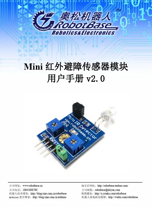
Mini红外避障传感器用户手册v2.0
- 格式:pdf
- 大小:2.68 MB
- 文档页数:11
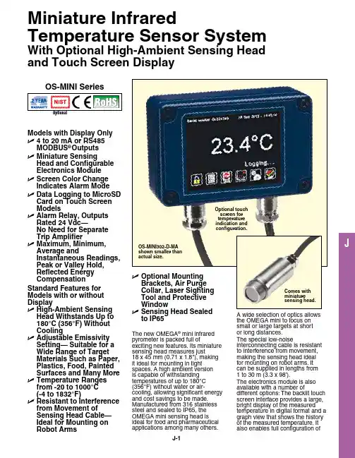
JModels with Display Only U 4 to 20 mA or RS485 MODbuS ®Outputs U M iniature SensingHead and Configurable Electronics Module U S creen Color Change Indicates Alarm Mode U D ata Logging to MicroSD Card on Touch Screen Models U A larm Relay, Outputs Rated 24 Vdc—No Need for Separate Trip Amplifier U M aximum, Minimum, Average andInstantaneous Readings, Peak or Valley Hold, Reflected Energy CompensationStandard Features for Models with or without Display U H igh-Ambient Sensing Head Withstands up to 180°C (356°F) Without Cooling U A djustable Emissivity Setting— Suitable for a Wide Range of Target Materials Such as Paper, Plastics, Food, Painted Surfaces and Many More U T emperature Ranges from -20 to 1000°C (-4 to 1832°F)U R esistant to Interference from Movement of Sensing Head Cable—Ideal for Mounting on Robot ArmsMiniature InfraredTemperature Sensor SystemWith Optional High-Ambient Sensing Head and Touch Screen Displayto IP65OS-MINI SeriesThe new Omega ® mini infrared pyrometer is packed full ofexciting new features. Its miniature sensing head measures just 18 x 45 mm (0.71 x 1.8"), making it ideal for mounting in tight spaces. a high ambient version is capable of withstanding temperatures of up to 180°C (356°F) without water or air-cooling, allowing significant energy and cost savings to be made. manufactured from 316 stainless steel and sealed to IP65, the Omega mini sensing head is ideal for food and pharmaceutical applications among many others.a wide selection of optics allows the Omega mini to focus on small or large targets at short or long distances.The special low-noiseinterconnecting cable is resistant to interference from movement, making the sensing head ideal for mounting on robot arms. It can be supplied in lengths from 1 to 30 m (3.3 x 98').The electronics module is also available with a number ofdifferent options: The backlit touch screen interface provides a large, bright display of the measured temperature in digital format and a graph view that shows the history of the measured temperature. It also enables full configuration ofOS-MINI302-D-MA shown smaller than actual size.Comes with miniature sensing head.Optional touch screen for temperature indication and configuration.the sensor including temperature range setting between-20 to 1000°C (-4 to 1832°F), adjustable filtering, peak or valley hold processing, emissivity setting and reflected energy compensation. In alarm conditions, the whole display changes color to provide an immediate and obvious alarm indication. alarm modes and levels can be configured via the touch screen. When fitted with a microsd card, the Omega minialso functions as a data logger,providing a useful means ofrecording process temperaturesfor quality assurance andtraceability. The user can selectthe sample rate and the numberof samples to be taken andschedule the data logging tostart at a certain time. With a2 gb card, the user can store28.4 million time and datestamped readings, which providesalmost 1 year’s worth of data atthe fastest possible sample rateof 1 per second.Output options include 4 to20 ma, Rs485 mOdbus andalarm relays, which are rated24 Vdc so there is no need fora separate trip amplifier. Otheroptions include mounting brackets,an air purge collar, protective lenscover and laser sighting tool.24 Vdc100 mA -CB and -CRT models 24 Vdc 100 mA-BB and -BT modelsConnectionsSpecificationsMaximum Temperature Span(Touch Screen Models): 1020°C (1868°F)Minimum Temperature Span (Touch Screen Models): 100°C (212°F)Output: 4 to 20 ma or Rs485 mOdbusAccuracy:is greaterRepeatability: ± 0.5°C or 0.5%, whichever is greaterEmissivity Setting Range: 0.20 to 1.00Emissivity Setting Method:MA Models: in electronics boxMODbuS Display Models: Via Rs485; via touch screenResponse Time, t90: 240 ms (90% response)Spectral Range: 8 to 14 μmSupply Voltage: 24 Vdc ± 5%Maximum Current Draw: 100 ma Maximum Loop Impedance(MA and MA-R-D Models): 900 Ω (4 to 20 ma output)Models):alarm relays rated 24 Vdc, 1 a,isolated 500 VdcCable Length (Sensing Head to Electronics Module): 1 m (3.3') (standard), up to 30 m (98.4')(optional)Ambient Temperature (Sensing MA and MA-R-D C4 and C4-R-DModels with Touch Screen DisplayModels with RS485/MODbuS OutputJModels with No DisplaySD card adaptor.* To order, specify model number, temperature range, output and interface, for an additional cost.** Insert cable length in meters. Extended cable is added to standard cable length, add suffix to model number, for an additional cost.Ordering Examples: OS-MINI152-D-MA, miniature infrared temperature sensor with 15:1 optics, touch screen and configurable temperature range from -20 to 1000°C (-4 to 1832°F).OS-MINI302-MA-XT, miniature infrared temperature sensor with 30:1 optics, 4 to 20 mA output and fix range from 0 to 1000°C (32 to 1832°F).OS-MINI-HA201-D-C4, miniature infrared temperature sensor with high ambient sensing head and 20:1 optics, RS485 MODBuS, relay and touch screen. OCW-3, OMEGACARE extends standard 2-year warranty to a total of 5-year warranty.OS-MINI152-MA-MT-MINI-PMCE-(3), miniature infrared temperature sensor with 15:1 optics, 4 to 20 mA output, 0 to 250°C (32 to 482°F) rangeand 3 m (10') of extension cable.Options and Accessories K Type High Ambient Sensing HeadAir purge collar.Laser sighting tool.Measurement Temperature Range Specify temperature range from table below.。

MINI SMD 数字AD 型热释电红外传感器Mini SMD AD Pyroelectric Infrared SensorsS22-P330Y 使用说明书V1.3森霸传感科技股份有限公司Senba Sensing Technology Co.,Ltd.森霸传感科技股份有限公司1.企业及产品概况:1.1体系认证●ISO14001认证公司获得ISO14001认证,在遵守国家环保法的基础上,通过采取各种改进措施,实现企业可持续性发展。
●ISO 9001认证公司获得国际标准化机构(ISO)的品质保证标准-即“ISO 9001”的认证。
1.2关于欧盟ROHS指令ROHS指令:欧盟提出的“关于在电子电气设备中限制使用某些有害物质的指令2011/65/EC”,公司生产的所有产品均符合欧盟ROHS指令。
1.3产品型号及检测原理1.3.1产品规格型号:本产品为SMD 数字AD 型双元热释电红外传感器,产品型号为S22-P330Y ,版本号为V1.3,若使用产品超出了产品列举的应用范围,请及时咨询产品应用或销售工程师。
1.3.2产品探测原理:传感器核心部件由热释电探测敏感元、红外滤光片和芯片IC三部分组成,其中探测敏感元为双元结构。
产品是将AD芯片与人体探测敏感元都集成在电磁屏蔽罩内的热释电红外传感器。
人体探测敏感元将感应到的人体移动信号传输到AD芯片上,其通过采集、滤波等输出16位数字信号,并通过外围电路的单片机实现相关功能。
2.非商业用途说明森霸传感科技股份有限公司(以下简称森霸)免费授权用户非商业性使用本产品说明书,并为用户提供产品变更和咨询服务。
若要进行商业性的销售、复制、散发或其他商业活动,须事先获取森霸的书面授权和许可。
另外,用户在使用本产品说明书时,不得违反法律、危害公共安全或损害第三方合法权益,森霸不承担由此引发的任何索赔责任。
3.产品说明3.1产品命名规则示例S:贴片型22:产品分类P:窗口:窗口尺寸4*43:感应单元:敏感元为双元结构3:脚位:功能脚位数量为30:红外滤光片:探测波长5-14um Y:芯片:表示其型号代码为YS22—P33Y森霸传感科技股份有限公司3.2产品特点⏹小型化⏹SMD回流焊贴装工艺⏹16位数字信号输出⏹单线串行数据⏹低电压、微功耗⏹适合超薄的产品外观设计3.3产品应用领域消费电子应用:⏹玩具⏹数码相框、门铃⏹电视机、冰箱、空调智能家居、安防应用:⏹USB报警器⏹入侵检测⏹网络摄像机⏹局域网监控器⏹私人警报器⏹汽车防盗系统灯饰应用:⏹室内、庭院、走廊、楼梯灯等的自动亮起和熄灯等3.4产品及推荐的焊盘尺寸图推荐焊盘尺寸图注:1、传感器双元结构,以X 向做左右横切运动时,其感应视角最大且探测距离最远。

P •Email: sensors@197 MINI-BEAM专家型TM传感器MINI-BEAM®专家型TM注意:i) 电缆式传感器型号后缀加“W/30”,电缆长度为9m(如:SME312FPB W/30)ii)型号后带QD的产品需另配接插件。
•Email: sensors@199 MINI-BEAM专家型TM传感器MINI-BEAM®专家型TM200MINI-BEAM 专家型TM 传感器M I N I -B E A M ®E x p e r t T M˝…¤31.2 mm(1.23")MINI-BEAM 专家型系列传感器(后缀LP ,LPC ,D ,DV ,CV ,CV2,CVG ,CVB ,及)电缆式接插件式MINI-BEAM 专家型系列传感器宽光束直接反射式(后缀为W 型)MINI-BEAM 专家型系列传感器玻璃光纤式(后缀为F ,FV ,FVG ,FVB 和FVW 型)MINI-BEAM 专家型系列传感器塑料光纤式(后缀为FP ,FPG ,FPB 和FPW 型)MINI-BEAM 专家型系列传感器-后视图 •Email: sensors@209 MINI-BEAM系列传感器MINI-BEAM®系列对于标准的MINI-BEAM:i) 电缆式传感器型号后加后缀“W/30”,电缆长度为9m(如:SM312FP W/30)ii) MINI-BEAM电缆式接插件型号后缀为“QDP”,长度150mm(如SM312FPQDP)iii) 型号后带QD的产品需另配接插件210MINI-BEAM 系列传感器M I N I -B E A M ®S e r i e s注意:直流MINI-BEAMs 如加上后缀“MHS ”(如:SM312LVMHS )则为高速型,响应时间0.3ms ,但同时减小了检测距离和过量增益。
•Email: sensors@211MINI-BEAM 系列传感器MINI-BEAM ®系列直流系列电缆式直流系列接插件式(4针Euro型)直流电缆式发射器直流接插件式发射器(4针Euro 型)4针Euro 型出线图可选接插件(QD )式直流MINI-BEAM 型传感器具有2m(6.5')或9m(30')的PVC 电缆,或是一个4针Euro 型的QD 接插件。
IR T1Small Area Infrared TransmitterMAN 212HIR T1 Small Area Infrared TransmitterImportant Safety InstructionsPlease read and keep these instructions.WARNING! To reduce the risk of fire or electric shock, do not expose the system to rain or moisture. Do not use this apparatus near water. The system should not be exposed to dripping or splashing, and objects filled with liquids such as beverages should not be placed on the transmitter or receivers. Clean only with a dry cloth.Attempting to service this device will void the warranty • Refer servicing to qualified personnel. Servicing is required when the system has been damaged in any way: if liquid has been spilled or objects have fallen into the unit, if the unit has been exposed to moisture, if the unit does notoperate normally, or if the unit has been dropped.• Do not block any ventilation openings. Install in accordance withmanufacturer’s instructions.• Do not install near any heat sources such as radiators, heat registers,stoves, or other apparatus that produces heat.• Use only attachments/accessories specified by the manufacturer.• Unplug the transmitter during lightning storms or when unused for long periods of time.• Be advised that different operating voltages require the use of differentattachment plugs. Check the voltage in your area and use the correct type.• Use only the power supply provided by Williams AV. Other power supplies may have similar specifications, but may not be equivalent in emissionsratings, in-rush current, etc. Use of an unapproved power supply may leave the device partially or completely inoperable, and will void the warranty.• Protect the power cord from being walked on or pinched, particularly atplugs, receptacles, and near the power jack on the transmitter.• This apparatus must be grounded.• The AC Power plug or an appliance coupler is used as the disconnectdevice, so the disconnect device should remain readily operable.For Customers in The United StatesThis equipment has been tested and found to comply with the limits for Class B digital device, pursuant to part 15 of the FCC rules.For Customers in CanadaThis Class B digital device meets all requirements of the Canadian Interference-causing Equipment Regulations. Cet appareil numérique de la classe B respecte toutes les exigencies du Règlement sur le matériel brouilleur du Canada.IR T1 Small Area Loop Infrared Transmitter Recycling InstructionsPlease help Williams AV protect the environment. Please take the time to dispose of your equipment properly.Product Recycling for Customers in the European Union:Please do NOT dispose of your Williams AV equipment in the householdtrash. Take the equipment to a electronics recycling center, or return theproduct to the factory for proper disposal.System OverviewThe IR T1 is a two-channel infrared transmitter combining infrared modulator and emitter technology into a single mountable enclosure—which reduces operating costs, eliminates the need for rack space and eases set-up.The IR T1 is ideal for high quality audio programs such as music, television audio, and audio description. The IR T1 will accept any line level stereo audio input. Infrared receivers detect the transmission and convert the light signals backinto audio signals. The IR T1 operating frequencies (2.3/2.8 MHz) minimize high efficiency lighting interference.No FCC license or radio approval is required with this equipment. It can be used anywhere in the world.NOTE: This equipment has been tested and found to comply with the limits fora Class B digital device, pursuant to part 15 of the FCC Rules. These limits are designed to provide reasonable protection against harmful interference when the equipment is operated in a commercial environment. This equipment generates, uses, and can radiate radio frequency energy and, if not installed and used in accordance with the instruction manual, may cause harmful interference to radio communications. Operation of this equipment in a residential area may cause interference, in which case the user will be required to correct the interference at his own expense.NOTE: A PLASMA MONITOR OR TELEVISION CAN DEGRADE THE AUDIO QUALITY OF THE IR T1 TRANSMITTER. FOR BEST PERFORMANCE, THE TRANSMITTER SHOULD BE POSITIONED AS FAR AWAY AS POSSIBLE FROM ANY PLASMA MONITOR, TELEVISION OR OTHER INTERFERING DEVICES. Installation ProceduresDetermine Coverage AreaWhen using the IR T1 transmitter with the RX22-4 receiver, the system coverage area will exceed 1,300 sq. ft. (120 sq. m.). Other receivers may have a reduced coverage area. Figure 1 illustrates typical coverage pattern for the IR T1. This can be affected by direct/indirect sunlight, reflections on walls, objects in the room and room construction. The patterns illustrated are the direct radiation pattern. Most objects block infrared light, so the transmitter cannot be concealed behind walls, glass, curtains, etc. The infrared radiation does not drop to zero outsidethe illustrated patterns; it decreases. It still may be useable at a greater distance, depending on the receiver sensitivity and the reflective characteristics of the room. Important: Remember to point the transmitter towards the listening audience. The front is the surface with the Williams AV logo as shown on the cover of this manual.See Figure 1 on the next page for a coverage pattern.IR T1 Small Area Infrared Transmitter Figure 1 - IR T1 Coverage PatternWIR RX22-4 Receiver - solid line || IR RX20 - dashed lineConnections & IndicatorsFigure 2 - IR T1 Rear ViewConnecting Power1. Snap in the correct adapter for your region into the TFP 055 power supply.2. Plug the USB end of the “USB to micro USB cord” into the power supply.3. Plug the micro USB end of the “USB to micro USB cable” into the IR T1.4. Plug the power supply into an AC outlet.Alternatively, you may plug the USB end of the cord into a direct USB power source, such as the USB port on a television, etc. to power the IR T1.On power up, the IR T1 performs a self-test to detect damage due to shipping, handling, tampering or incorrect operation. If any failure is present, the green power LED will blink rapidly. If this occurs, contact Williams AV Customer Service. This system is designed for class 2, low-voltage wiring. Always follow local electrical codes when using low-voltage wiring.IR T1 Small Area Loop Infrared Transmitter Audio Indicators (Ch. 1,2)The audio indicator LEDs (see Figure 2) will light up yellow when an adequate level of input audio is sensed on that channel. If audio is present, but not high enough to produce acceptable audio quality, the LED will not light. Once an adequate level of audio is fed to the unit, the LED will stay on. If the audio level falls below the acceptable threshold, the LED will go out, and the sleep timer will start to turn off that channel after approximately 12 minutes (See “Sleep Mode” below).Sleep ModeThe IR T1 is equipped with a sleep mode/power save feature. If a minimum acceptable audio level is not present on a channel (both channels are independent), a timer begins, and after approximately 12 minutes that channel will automatically go into sleep/power save mode. The timer begins when the yellow channel LED goes out. Both channels are independent; one can be broadcasting while the other goes to sleep (shuts off infrared output).This mode decreases power consumption by 80 percent. Audio will automatically begin broadcasting again when the audio input threshold is triggered.Connecting the Audio SourceThe IR T1 detects the presence of audio on the Audio Line Input jack, lights up the LED for the channel(s) where an adequate level of incomiing audio is present, and transmits on either/both channels.The IR T1 will accept line level mono or stereo audio inputs. See figure 3 for audio input cable configuration.The IR T1 uses a limiter circuit to control the gain of line level audio for optimum transmission. The yellow Audio Indicator LED should stay on when when an adequate level of input audio is present. If the audio indicators do not stay on, the audio level is too low. Adjust the gain of the audio source up until they stay on. Figure 3 - 3.5mm plug/input jack wiringOptional Receiver(s)WIR RX22-4 4-Channel, Body Pack Receiver (requires earphones, headphones, or neckloop)WIR RX20 2-Channel, Under-the-Chin ReceiverIR T1 Small Area Infrared TransmitterTroubleshootingThe IR T1 is equipped with a series of self-tests. If the power indicator on the unit is blinking rapidly, an error has occurs which requires returning the unit for service. The IR T1 “Power Indicator” is not lit:• Make sure the power supply is plugged into the transmitter and any remote power switch is on.• Make sure the electrical outlet is on.• Make sure the 5 VDC USB power supply is working.The IR T1’s Ch1 or Ch2 “Audio Indicator” does not light:• Make sure the IR T1 is plugged in.• Make sure the audio input is connected properly. Refer to figure 3.• Make sure an active and adequate level of audio signal is being sent to the IR T1 transmitter.No Sound through Receivers:• Check to make sure the receiver is operating on the same frequency as the transmitter.• If some of the receivers work but others don’t, check for bad batteries or earphones.• If none of the receivers work, check to see if the power and audio input cables are connected to the transmitter. Verify that the “Power Indicator” LED is on, and Ch1 or Ch2 “audio indicator” LED(s) are on.• Make certain the transmitter is not covered by objects which would block infrared light.Sound Through the Receivers is Weak and Noisy:• Make certain the user is facing towards the transmitter. Move the user closer to the transmitter, or reposition the transmitter closer to the user as appropriate.• Try adjusting the audio input level on the source.• Reposition the transmitter beam, making certain the front (curved) face of the transmitter is pointed directly towards the listener.Buzzing or Humming Noise in Sound System:• Check for ground loops or noise on the input signal.If these instructions do not address your problem or the issue persists, please call your authorized Williams AV dealer or representative.Mounting Options• STD 008 – TV Top Shelf (optional)• BKT 024 - Universal wall / ceiling mount (optional)• The IR T1 can be mounted on any camera tripod stands with a 1/4” - 20 threaded connectorIR T1 Small Area Loop Infrared Transmitter Infrared Transmitter SpecificationsModel IR T1Dimensions:Width: 5.65”(14.4 cm), Depth: 3.65”(9.3 cm), Height:1.15”(2.9 cm)Weight:8.3 oz (235 g)Color:BlackPower Supply:TFP 055 – 100-240VAC 50/60Hz Input, 5VDC, 0.2A USBOutput, Universal Supply with international adaptersOther USB Power Supply (must be at least 5VDC, 0.2A) Power Cable:USB to micro USB cableDC Power Input:Micro USB connector, 5VDC, 0.2APower Indicator:Green LEDSleep/Power Save Mode:Shuts off carrier when no audio present for 12 minutes Modulation:FM Wideband, ±50 kHz deviation max, 50 μS pre-emphasisCarrier Frequencies: 2.3MHz (Ch 1) and 2.8MHz (Ch 2)Default at power on = carriers off. Carriers areautomatically enabled upon presence of audio. Coverage Area:1,300 sq. ft (120 sq. m.) with the WIR RX22-41000 sq. ft. (93 sq. m.) with the IR RX20Audio Inputs: 3.5mm stereo line level input jack, Ch 1 connected to tip,Ch 2 connected to ring, GND connected to sleeve Audio Indicators:One Y ellow LED per channel, lights up and stays onsteady with minimum audio level.Signal-to-Noise Ratio:70 dB at onset of limitingFrequency Response:100 - 12,000 HzOperating Requirements:32°-122°F (0-50°C)Mounting Kit:Optional: STD 008 TV Top Shelf Mounting KitOptional: BKT 024 Omnidirectional mount for wall orceiling mountingCompatible Receivers:WIR RX22-4, IR RX20Warranty: 2 yearsApprovals/Regulatory Compliance:CE, RCM, FCC, Industry Canada, PSE, CUL, WEEE, RoHS, CB SchemeNOTE: Specifications are subject to change without notice.Visit our website for the latest specifications and publications: Hereby, Williams AV declares that the infrared equipment is in compliance withDirectives 2014/30/EU, 2014/35/EU and other Union harmonization as applicable. The full text of the EU declaration of conformity is available by contacting Williams AV at the following email address: *************************Limited WarrantyWilliams AV products are engineered, designed, and manufactured under carefully controlled conditions to provide many years of reliable service. Williams AV warrants the IR T1 infrared listening system against defects in materials and workmanship for two (2) years. During the first two years from the purchase date, we will promptly repair or replace the IR T1 infrared listening system. Microphones, earphones, headphones, batteries, chargers, cables, carry cases, and all other accessory products carry a 90-day warranty.WILLIAMS AV HAS NO CONTROL OVER THE CONDITIONS UNDER WHICH THIS PRODUCT IS USED. WILLIAMS AV, THEREFORE, DISCLAIMS ALL WARRANTIES NOT SET FORTH ABOVE, BOTH EXPRESS AND IMPLIED, WITH RESPECT TO THE IR T1 INFRARED LISTENING SYSTEM, INCLUDING BUT NOT LIMITEDTO, ANY IMPLIED WARRANTY OF MERCHANTABILITY OR FITNESS FOR A PARTICULAR PURPOSE. WILLIAMS AV SHALL NOT BE LIABLE TO ANY PERSON OR ENTITY FOR ANY MEDICAL EXPENSES OR ANY DIRECT, INCIDENTALOR CONSEQUENTIAL DAMAGES CAUSED BY ANY USE, DEFECT, FAILUREOR MALFUNCTIONING OF THE PRODUCT, WHETHER A CLAIM FOR SUCH DAMAGES IS BASED UPON WARRANTY, CONTRACT, TORT OR OTHERWISE, THE SOLE REMEDY FOR ANY DEFECT, FAILURE OR MALFUNCTION OFTHE PRODUCTS REPLACEMENT OF THE PRODUCT. NO PERSON HAS ANY AUTHORITY TO BIND WILLIAMS AV TO ANY REPRESENTATION OR WARRANTY WITH RESPECT TO THE IR T INFRARED LISTENING SYSTEM. UNAUTHORIZED REPAIRS OR MODIFICATIONS WILL VOID THE WARRANTY.The exclusions and limitations set out above are not intended to, and should not be construed so as to contravene mandatory provisions of applicable law. If any part or term of this Disclaimer of Warranty is held to be illegal, unenforceable, or in conflict with applicable law by a court of competent jurisdiction, the validity of the remaining portions of this Disclaimer of Warranty shall not be affected, and all rights and obligations shall be construed and enforced as if this Limited Warranty did not contain the particular part or term held to be invalid.If you experience difficulty with your system, call toll-free for customer assistance: 1-800-843-3544 (U.S.A.) or +1 952 943 2252 (outside the U.S.A.)If it is necessary to return the system for service, your Customer Service Representative will give you a Return Authorization Number (RA) and shipping instructions.Pack the system carefully and send it to:Williams AVAttn: Repair Dept.10300 Valley View RoadEden Prairie, MN 55344 USAY our warranty becomes effective the date you purchase your system. If your sales receipt is not available, the date code on the product will determine your warranty status.*******************/800-843-3544 / INTL: +1-952-943-2252©2021 Williams AV • All Rights Reserved MAN 212H。

Smallest displacement sensor in class* A mong devices equipped with displays in the 1 μm repeat accuracy class. Optex FA examination performed November 2015.Newly added amplifier unit that can be connected with CC-Link communication unitsBuilt-in amplifier & digital 4-digit displayFeaturing high performance functionality like high-end modelsRelated productsCC-Link communication UC1P .118Remote operation/calculation CDAP .450Specular reflection typeCD33P .47218 × 31 × 44 mm (W × D × H). The FASTUS CD22 series has achieved being the smallest displacement sensor in its class by adopting a new type of hybrid lens for the optical system and by integrating accumulated optical technology. By utilizing Optex FA’s know-how regarding the completion of measurement processing inside the sensor head, a feedback circuit that is the same as those on high-end displacement sensors has been equipped within the compact body.*Among devices equipped with displays in the 1 μm repeat accuracy class.Optex FA examination performed November 2015.Smallest in class*W18 × D31 × H44 mmPositioning for metal plate mountingDetection of presence/height of electronic componentsSlackness measurements for rubber materialsElectrode thickness measurement464Compact laser displacement sensor CD22 series Selection tableFor the pig tail type, please purchase an optional connector cable.When using a CDA amplifier unit, please select the RS-485 communication type.Regarding stainless steel housingtype (made-to-order)A type that features SUS316L for the housing can also bemade.ConnectorcablesDisplacement sensor amplifier unitCDA seriesOptionsDOL-1205-G02MCable length: 2 mDOL-1205-G05MCable length: 5 mDOL-1205-G10MCable length: 10 mCDA-M(master unit)CDA-S (slave unit)DOL-1205-G02M-RCable length: 2 m, robot cable typeDOL-1205-G05M-RCable length: 5 m, robot cable type* I mage shows DOL-1205-G02M. Robot cable type feature black instead of orange and shapes vary slightly.Features an organic EL display that can display clearly in bothJapanese and English.This external amplifier can be used for calculations using twoCD22 series units or connected to a CC-Link communicationunit.*For details, refer to page 450.Compact laser displacement sensor CD22 seriesFeaturesIdeal for robot mountingCD22 series models feature a compact and lightweight body, and because of their built-in amplifier, there are few limitations on installation space and wiring, meaning that sensors themselves can be mounted on robots or on moving parts.Connect with CC-Link to achieve “sensor visibility”By connecting a CDA series to a communication unit, connection to a CC-Link network is possible.It supports Mitsubishi iQ Sensor Solution (iQSS) and batch management of sensors can be performed easily with GX Works2.CC-Linkcommunication unit UC1Easy-to-see digital panelFeaturing an ultra-small body and easy-to-see built-in 4-digit digital panel meter.Confirmation of distance can be performed on the spot and the 4 operation buttons provide multi-functionality whileenabling easy operation.The housing features aluminum die-casting that suppresses measurement errors caused by temperatures or housing distortion.OUT: ON when output is ON ZERO: ON when zero reset is usedMANUAL: ON when "Extension mode"LASER: ON during laser emissionCC-Link communication unitUC1 series*For details, refer to page 118.The external amplifier unit enables remote operation and easy calculation settingWith its excellent visibility and operability, the external amplifier unit enables the CD22 series to be operated remotely even when mounted in narrow spaces such as inside machinery.Calculation of thickness and height differences can be performed easily using 2 sensor heads.Displacement sensor amplifier unitCDA series*For details, refer to page 450.Compact laser displacement sensor CD22 seriesHigh-accuracyWith the CD22 series, the causes of all measurement errors can be eliminated even in the case of workpieces in which highly accurate measurements were difficult thanks to “Tri-CORE” optimization technology that corrects receiving light waveforms by way of “digital sub-pixel processing”, a “high resolution electric shutter” and “unique algorithm”.Automatic sampling functionWith the CD22 series, in addition to normal receiving light quantity feedback, a “Sampling period: AUTO” mode has also been equipped that automatically adjust the sampling period when there are only low levels of reflected light from the workpiece.Thanks to this, high-speed measurements of even black workpieces and metal workpieces with low levels of reflected light are possible.Alarm hold functionAlarms may be generated during measurement due to small holes in the workpiece, etc.CD22 series models are equipped with an “alarmhold function” that enables the time until an alarm is identified to be set. It is possible to configure settings so that an alarm is not generated in the case of small holes, but is generated when there is no workpiece.During high-speed samplingresulting in some sections not being able to be measuredDuring low-speed samplingShape cannot be correctly obtainedworkpieces can be correctly obtainedWorkpiece in which receiving light quantity is decreased due Sampling period: When xedelectricalgorithmWhen alarm hold is not usedMeasurement not possible (9999)When alarm hold is usedAlarm holdCD22-15CD22-35 CD22-1000.21015Measurement distance (mm)L i n e a r i t y (%F S )200.10−0.1−0.2−0.3−0.4−0.50.30.40.50.220Measurement distance (mm)L i n e a r i t y (%F S )500.10−0.1−0.2−0.50.30.40.5−0.3−0.430400.25060708090110120130140100Measurement distance (mm)L i n e a r i t y (%F S )1500.10−0.1−0.2−0.3−0.4−0.50.30.40.5Black rubberStainless steel plateWhite ceramic (speci cation)Linearity characteristics data Low deviation depending on the workpieceCompact laser displacement sensor CD22 seriesSpecificationsAnalog output type¢Array Array<Measurement conditions>The measurement conditions are as follows unless otherwise designated: Ambient temperature: 23°C (normal temperature), Supply voltage: 24 VDC, Sampling period: 500 μs, Average number of times: 64, Center of measurement range, Measurement target: white ceramic.*1 A Class 1 type can also be made available (made-to-order product).*2 I n accordance with the FDA provisions of Laser Notice No. 50, the laser is classified as Class 1 or Class 2 per the IEC 60825-1 standard.*3 D efined with center strength 1/e2 (13.5%) at the center of measurement range. There may be leak light other than the specified spotsize. The sensor may be affected when there is a highly reflective object close to the detection area.*4 With an average of 512 times*5 In the case of the analog voltage output type, use a supply voltage of 12.0 VDC Minimum to obtain the proper output.RS-485 communication type¢<Measurement conditions>The measurement conditions are as follows unless otherwise designated: Ambient temperature: 23°C (normal temperature), Supply voltage: 24 VDC, Sampling period: 500 μs, Average number of times: 64, Center of measurement range, Measurement target: white ceramic.*1 A Class 1 type can also be made available (made-to-order product).*2 I n accordance with the FDA provisions of Laser Notice No. 50, the laser is classified as Class 1 or Class 2 per the IEC 60825-1 standard.*3 D efined with center strength 1/e2 (13.5%) at the center of measurement range. There may be leak light other than the specified spotsize. The sensor may be affected when there is a highly reflective object close to the detection area.*4 With an average of 512 times*5 Multi-drop connections by way of station number settings are not supportedCompact laser displacement sensor CD22 seriesI/O circuit diagram¢ Analog output type: With the NPN setting¢ Analog output type: With the PNP setting¢ Connector pin configuration(Sensor side)Brown 1Gray 3Black 2Blue 5White 4M12 connectorAnalog output typeBrown 1 12 to 24 VDC Black 2 Control output Gray 3 External input White 4 Analog output Blue 5 0 VRS-485 communication typeBrown 1 12 to 24 VDC Black 2 RS-485 (A)Gray 3 Not used White 4 RS-485 (B)Blue 5 0 VCompact laser displacement sensor CD22 series DimensionsSensorPig tail type Cable type(Unit: mm)Connector cables ¢ DOL-1205-G02M¢DOL-1205-G05M¢DOL-1205-G10M Connector cable (robot cable specification)¢ DOL-1205-G02M-R¢DOL-1205-G05M-RCable section material: PVCConductor cross-section: 5-wire × 0.5 mm2Cable section material: PVCConductor cross-section: 5-wire × 0.3 mm2 Precautions for laser useThis product emits a Class 1 or Class 2 visible laser beam that is compliant with JISC6802/IEC -60825-1/FDA laser safety standards. Labels for applicable standards areaffixed and attached to the sides of the sensor.Export to the United StatesIf this product is to be exported to the United States,it is necessary to follow laser standards as stipulatedby the American Food and Drug Administration(FDA). This product has already been submitted tothe CDRH (Center for Devices and RadiologicalHealth). If exporting to the United States, apply theattached seal to the product or replace the seal.Type of laser used in this product。

MINI-MDVRShenzhen Technology Co., Ltd.版权所有侵权必究All rights reserved目录1产品介绍 (3)1.1产品概述 (3)1.2产品的主要功能 (3)1.3性能参数 (3)2操作说明 (5)2.1前面板 (5)2.2后面板............................................................................................ 错误!未定义书签。
2.3遥控器 (5)3基本操作手册............................................................................................. 错误!未定义书签。
3.1系统的开启与登陆.......................................................................... 错误!未定义书签。
3.1.1系统开启 ........................................................................................ 错误!未定义书签。
3.1.2系统登陆 ........................................................................................ 错误!未定义书签。
3.2系统的查询与设置.......................................................................... 错误!未定义书签。
3.2.1设备操作 ........................................................................................ 错误!未定义书签。

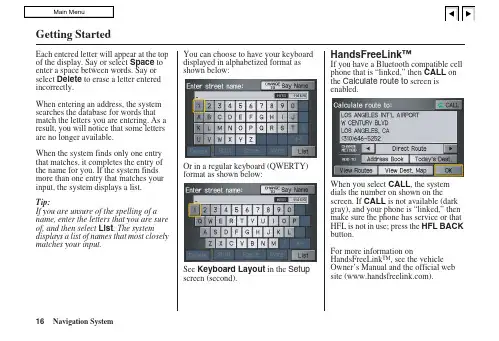
Getting StartedEach entered letter will appear at the top of the display. Say or select Space to enter a space between words. Say or select Delete to erase a letter entered incorrectly.When entering an address, the system searches the database for words that match the letters you are entering. As a result, you will notice that some letters are no longer available.When the system finds only one entry that matches, it completes the entry of the name for you. If the system finds more than one entry that matches your input, the system displays a list.Tip:If you are unsure of the spelling of a name, enter the letters that you are sure of, and then select List. The system displays a list of names that most closely matches your input.You can choose to have your keyboarddisplayed in alphabetized format asshown below:Or in a regular keyboard (QWERTY)format as shown below:See Keyboard Layout in the Setupscreen (second).HandsFreeLink™If you have a Bluetooth compatible cellphone that is “linked,” then CALL onthe Calculate route to screen isenabled.When you select CALL, the systemdials the number on shown on thescreen. If CALL is not available (darkgray), and your phone is “linked,” thenmake sure the phone has service or thatHFL is not in use; press the HFL BACKbutton.For more information onHandsFreeLink™, see the vehicleOwner’s Manual and the official website ().16Navigation SystemGetting StartedSystem Start-upWhen you turn the ignition to ON (II), it takes several seconds for the navigation system to boot up.The first screen to appear is the navigation system globe screen. The screen then changes to the Disclaimer screen:NOTE:The OK button does not appear immediately. It appears after the software is loaded.Read this disclaimer carefully so youunderstand it before continuing. Push inon the joystick, or touch OK, and themap screen will appear on the display.The “OK” cannot be activated by voice.If you do not press the joystick or touchOK, the screen will go dark after 30seconds. To return to the Disclaimerscreen, press any navigation or voicecontrol button.NOTE:If you do not select OK, and then enterthe Setup or Information screens, someitems are not available, and will showup as darkened buttons (grayed out).See System Function Diagram onpage 20.If you have entered any Calendarreminders, they are displayed after youselect OK.The Calendar reminder screenremains displayed until you select OK,Remind Later or press the CANCELbutton.If you select OK, the reminder will notshow up again. If you wish to have thereminder show up again later in the day,touch the Remind Later button.If you press the CANCEL button, themessage will be displayed the next timeyou start the vehicle.NOTE:The system will display the currentmessage and any older or previouslyunread messages, with the newestmessage listed first.Navigation System 17。
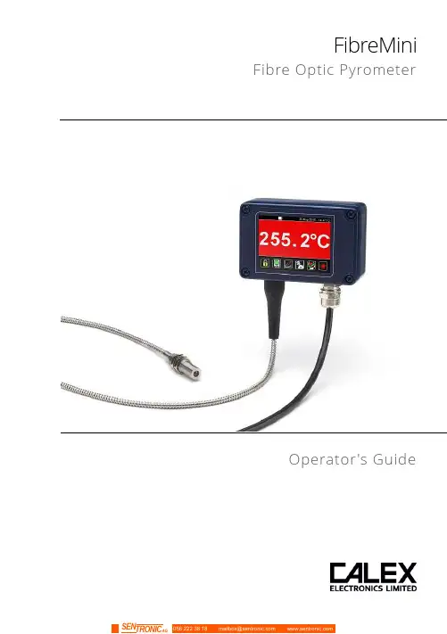
FibreMini Fibre Optic PyrometerOperator's GuideFibreMiniThe FibreMini is an infrared temperature sensor (pyrometer) with a fibre optic sensing head and separate electronics module.The fibre optic sensing head withstands ambient temperatures of up to 200°C and contains no electronics, so it may be used in areas of strong electromagnetic interference. Continuous laser sighting illuminates the position and size of the measurement spot while readings are being taken, without affecting the accuracy of the measurement.A touch screen interface is built into the electronics module, with temperature display, sensor configuration, data logging to optional MicroSD Card, and configurable alarm relay outputs. The sensor works by detecting the infrared radiation emitted from a surface as a result of its own temperature. The amount of radiation emitted is related to the temperature, and the sensor uses this relationship to provide an accurate temperature output.FibreMini sensors are ideal for measuring the surface temperature of many reflective metals in high-temperature applications, including iron and steel, as well as non-reflective non-metals.SpecificationsMeasurement SpecificationsData Logging SpecificationsTouch Screen Interface SpecificationsMechanical SpecificationsEnvironmental SpecificationsThis product is CE marked and RoHS compliant.Electromagnetic Compatibility StandardsConforms to EMC Directive EN61326-1:2006 (Electrical equipment for measurement, control and laboratory use – Industrial) as well as industrial standards for electromagnetic immunity and emissions.Model NumbersFM2.2 - 301 - MT - CRT - 3MFibre OpticCable Length3M = 3 metres5M = 5 metres10M = 10 metresOutput and InterfaceCRT = 4-20 mA output, two alarmrelay outputs, with touch screenBRT = RS485 Modbus output, twoalarm relay outputs, with touchscreenTemperature RangeMT = 250°C to 1000°CHT = 450°C to 2000°CField of View301 = 30:1 divergent optics751 = 75:1 divergent opticsSeriesFM2.2 = FibreMini pyrometer with 2.2 µm spectral responseField of View DiagramsDiagrams show the diameter of the measured spot at each distance, for 90% energy. The sensor will also measure at longer distances than the diagrams show. Measurement accuracy is not affected by distance, however the measured spot size will be larger at longer distances.Emissivity AdjustmentThe default emissivity setting is 0.95. This may be adjusted via the touch screen interface: Settings → Emissivity & CompensationEnter the emissivity of the target surface here. For more information on how to find the target emissivity, contact Calex.Reflected Energy CompensationSettings → Emissivity & CompensationSome of the infrared energy detected by an infrared temperature sensor is not emitted by the target, but is a reflection of its surroundings.To ensure an accurate reading, the sensor needs to know the temperature of the source of that reflected energy. In most applications, the surfaces that surround the target have the same temperature as the sensor itself (e.g. the sensor and target are in the same room). The sensor automatically compensates for the reflected energy, so this setting is not required and should be switched off.However, in some applications, the source of the reflected energy (the surroundings of the target) is much hotter or colder than the sensor itself. In these cases, Reflected Energy Compensation should be enabled and set to the temperature of the surroundings of the target.For example: if the target is inside a furnace and the sensor is outside, the reflected energy is coming from the inner walls of the furnace. Enter the furnace temperature into “Reflected Temperature” and select “Enable Reflected Energy Compensation”.For assistance, contact Calex.Alarm OutputsThe sensor has two alarm relay outputs, rated 24 V DC, 1 A. They are individually configurable via the touch screen interface.Each alarm can be configured as Low or High, with set point and hysteresis.For more information, see “Alarms”.Touch Screen InterfaceThe backlit touch screen interface provides a large, bright display of the measured temperature, two alarm relay outputs, and options for full configuration of the sensor.Using the Touch Screen InterfaceDisplays a large indication of the measured temperature. Thebackground turns bright red when an alarm is activated.MicroSD Card StatusThis icon is displayed when a MicroSD card is inserted, andflashes when data logging is in progress.Scheduled LoggingThis icon is displayed when scheduled data logging isenabled and has yet to begin.Temperature Units °C and °FPress “°C” to switch to °F and vice versa. The units arechanged throughout the interface.Display OptionsPress the measured temperature to select which reading isshown:Average Temperature: The measured temperaturewith averaging, but without hold processing.Hold Temperature: The measured temperature,with averaging and hold processing.Unfiltered Temperature: The unprocessedmeasured temperature.Sighting On/OffSwitches the laser sighting light on or off. The light does notaffect the measurement accuracy.Start/Stop LoggingManually begins or ends data logging (requires MicroSDCard, available separately).If Scheduled Start is enabled in Settings > Data Logging,then logging cannot be started manually.To manually start logging, you must first disable ScheduledStart.Acknowledge AlarmsSwitches the relay outputs for triggered alarms to theirnormal, untriggered state. The background of theTemperature View and Graph screen will stay red, and thealarms will not be triggered again until they are reset (seeLock/UnlockPrevents settings being changed via a four-digit numerical code.To unlock the sensor, enter the password and press the Unlock icon. The default password is 1234.Change PasswordEnter, confirm and save a new four-digit code.GraphDisplays the recent history of the Filtered Temperature and the Sensor Temperature. To scroll backwards and forwards in time, touch the graph and drag it. The graph stores the most recent 24 hours of temperature data.Reset GraphClears and restarts the graph.Return to Scrolling ViewReturns the graph to the real-time scrolling view, showingthe most recent measurements.SettingsAccess the configuration parameters. Press Apply to save the settings, or Exit to leave the screen without saving.SettingsData LoggingConfigure the storage of temperature data and alarm events. A MicroSD Card (optional) must be inserted to use these features.Emissivity & Compensation Settings4 to 20 mA Output (-CRT models) Modbus Address (-BRT models)Output ProcessingAveraging PeriodSelect the required averaging period to smooth the output and slow down the sensor’s response time.Note: averaging prevents the sensor from following rapid temperature changes.Hold ModeWith Peak or Valley Hold, the sensor will continue to display or outputa peak or valley in the measured temperature for a certain time.This feature is ideal for monitoring the temperature of individualobjects on a conveyor, and for ignoring unwanted low readings,such as when a rotating stirring arm in a container of liquidpasses the sensor.PeakThe output returns to the measured temperature after theHold Period.ValleyValley Hold operates in the same way as Peak Hold, exceptthe sensor holds the lowest temperature measuredduring the Hold Period.OffDisables hold processing.Hold PeriodThe peak hold period.AlarmsThe settings for the Alarm 1 and Alarm 2 relay outputs are configured individually.Manually Reset AlarmsAlarm 1 and Alarm 2Manualon the Temperature View oron the Alarms screen.AlarmsAlarm Operation with Hysteresis and Automatic ResetData LoggingData Logging SettingsAlarm Logging SettingsAlarm events can be logged to the MicroSD Card. Alarm log files andsettings are independent from Data Logging.Data LoggingThe sensor can be used as a standalone data logger.Data is stored on a MicroSD card in .csv format and can be viewed and edited easily using spreadsheet software. The MicroSD card is available as an optional accessory, with an SD Card adapter to transfer data to a PC.With a 2 GB card, the user can store 28.4 million readings, which is almost 1 year’s worth of data at 1 sample per second. Larger cards provide more storage.The MicroSD card slot and battery holder are located on the touch screen circuit board in the lid of the electronics module. Readings are time and date stamped using the unit’s internalclock. The clock is reset when the power is disconnected, or it will continue if the optional battery is fitted.Using the Sensor as a Data Logger1. Insert a MicroSD card into the holder on the circuit board inside the lid of the electronics module.2. To retain the date and time when the unit is switched off, fit a battery to the holder on the circuit board inside the lid.3. Replace the lid and connect the sensor power supply.4. To set the number of samples to be logged, the time period between samples, and, if required, to schedule data logging to automatically start, press to access the Settings menu, then press to access the Data Logging options.5. To save data logging settings, press6. To manually start data logging, press on the Temperature View.7. While logging is in progress, the logging icon flashes on the Temperature View.8. To stop data logging, press9. To transfer data to a computer, remove the MicroSD Card from the unit, insert the card into the SD Card adapter (supplied with the MicroSD Card, accessory model MSD) and insert the adapter into an SD Card reader.Installation of MicroSD Card and BatteryThe MicroSD Card and battery slots are located on the touch screen circuit board. Unscrew the lid of the electronics module to access them.The battery is optional. With a battery fitted, the internal clock will continue to run when the power is off. Without a battery, the unit will request the date and time each time the power is cycled.All other settings are stored in permanent memory and will be preserved when it is switched off, regardless of whether a battery is fitted.Data Log FilesData is saved to the MicroSD Card in .csv format. This file format can be opened or imported by spreadsheet software such as Microsoft Excel.A new folder is created on the MicroSD Card for each day that data is logged.A new log file is created every time logging is started. The start time is used as the file name. AccessoriesA range of accessories to suit different applications and industrial environments is available. These may be ordered at any time and added on-site. The following accessories are available from Calex:Fixed mounting bracketAdjustable mounting bracketAir purge collar: The air purge collar is used to keep dust, fumes, moisture, and other contaminants away from the lens. It must be screwed fully onto the sensing head. Air flow should be 5 to 15 l/min. Clean or ‘instrument’ air is recommended.MicroSD Card: Stores logged data. Includes SD Card adapter.OptionsAn optional Calibration Certificate is available if ordered at the same time as the sensor. This UKAS traceable certificate shows the measured temperature at three points across the sensor's temperature range. Contact Calex for details.InstallationThe installation process consists of the following stages:- Preparation- Mechanical installation- Electrical installationPlease read the following sections thoroughly before proceeding with the installation. PreparationDistance and Spot SizeThe size of the area (spot size) to be measured determines the distance between the sensor and the target. The spot size must not be larger than the target. Choose a suitable mounting distance so that the measured spot size is smaller than the target.ReflectionsThe sensor must be installed in a location where energy from lamps, heaters and sunlight cannot be reflected from the target into the lens. This is especially important for low- temperature targets. Using shields may help in this respect. For further information and assistance, contact Calex.Ambient TemperatureThe sensing head may be used between 0°C and 200°C ambient temperature.The electronics module may be used between 0°C and 60°C ambient temperature. Ensure the temperature of the electronics module remains stable, and allow 20 minutes for the unit to adjust to large changes in ambient temperature.Atmospheric QualitySmoke, fumes, dust or steam can contaminate the lens and cause errors in temperature measurement.In these types of environment, the amount of contaminant should be minimised, and the air purge collar should be used to help keep the lens clean.Electrical InterferenceThe sensor is tested to industrial standards for electromagnetic compatibility (EMC). To minimise electromagnetic interference or ‘noise’, the electronics module should be mounted away from motors, generators and such like.The fibre optic sensing head of this pyrometer contains no electronics and may be mounted where electromagnetic interference prevents the other types of sensor from working properly.Power SupplyThe required supply voltage is 24 V DC. Ensure the power supply is of the correct voltage and is capable of providing an output current of at least 100 mA.Mechanical InstallationAffix the sensing head to its mounting. The sensor can be mounted on brackets of your own design, or you can use the mounting bracket accessory.- Switch on the laser sighting to illuminate the measured spot, and adjust the angle of the sensor to aim it.- Ensure the target is larger than the illuminated spot. If not, adjust themeasurement distance for a smaller spot size.Note: The sensor housing must be connected to earth at one point, either the sensing head, the electronics module, or the output cable shield termination. To avoid ground loops, please ensure the sensor is grounded at only one of these points.Electrical InstallationCheck the distance between the sensing head and the electronics module, and between the electronics module and the instrumentation. If necessary, the sensor can be ordered with a longer fibre optic cable between the sensing head and the electronics module.The cable from the electronics module should have an outer diameter between 3.0 and 6.5 mm, with conductors of size 28 to 18 AWG.The terminal blocks may be removed from the electronics module for easy wiring. IMPORTANT: Ensure wiring is correct before switching the power on. Always switch off the power before connecting or disconnecting the sensor.Do not disconnect the touch screen circuit board from the main circuit board while the power is on.Wiring (-BRT models)When connecting several sensors in a single Modbus network, all of the sensors should be connected via a junction box to a single network bus cable, running from the furthest sensor to the Modbus Master.Up to 247 sensors may be connected to a single Modbus network. Each sensor must have a unique Modbus address. Sensors are normally shipped with Modbus address 1. This may be changed using the touch screen interface or via Modbus.To help prevent data reflections, please ensure the cable between each sensor and the main network bus is as short as possible. The network bus should be terminated with a resistor of 120Ω between the RS+ and RS- wires. The PWR- wire of the bus should be connected to the signal ground of the Modbus Master.OperationOnce the sensor is in position and the appropriate power, air and cable connections are secure, the system is ready for continuous operation by completing the following simple steps:1.Turn on the sensor power supply2.Turn on the connected instrumentation3.Read, monitor or log the temperatureImportantBe aware of the following when using the sensor:•If the sensor is exposed to significant changes in ambient temperature (hot to cold, or cold to hot), allow 20 minutes for the temperature to stabilise before taking orrecording measurements.•The electronics module should be positioned away from sources ofelectromagnetic interference. However, the sensing head may be positioned inareas of high electromagnetic interference.•Wires must be connected only to the appropriate terminals.•Do not attempt to open the black cover on the sensor inside the electronics module. Doing so will void the warranty.Viewing through a windowThe sensor is capable of measuring the temperature of a target through a window made of a suitable material transmissive to infrared radiation at 2.0 to 2.6 microns. The emissivity setting of the sensor should be adjusted to compensate for the presence of the window. Please contact Calex for more information on using the sensor with a window.MaintenanceOur customer service representatives are available for application assistance, calibration, repair, and solutions to specific problems. Contact our Service Department before returning any equipment.In many cases, problems can be solved over the telephone. If the sensor is not performing as it should, try to match the symptom below to the problem. If the table does not help, call Calex for further advice.TroubleshootingLens cleaningThe lens must be kept clean and dry for maximum accuracy. Check the condition of the lens regularly.If the lens has become dirty, the measurement accuracy will be affected. Blow off loose particles (if not using the air purge accessory) with an air “puffer”.PasswordThe default password is 1234. The password may be changed via the interface. GuaranteeCalex guarantees each instrument it manufactures to be free from defect in material and workmanship under normal use and service for the period of two years from the date of purchase. This guarantee extends only to the original buyer according to Calex Terms and Conditions of Sale.Issue C – June 2019。
********************Smart Air Quality MonitorSensedge MiniEnglish Español Deutsch Français 中文1 5 9 13 17ContentsThe Sensedge Mini is a building-grade air quality monitor. This user manual will provide a basic guide to its first use. Further information can be found on the Kaiterra Support Portal at /sensedge-miniGetting StartedAir is drawn into the Sensedge Mini from the lower side, as well as the air intake on the upper side. It is vital that neither side of the device is covered. Any changes in airflow may affect the readings and accuracy.USB-C: Only use the cable and charger/adapter supplied with the device DC direct wiring: Used for power supply of 12-30V DCPoE (Power over Ethernet): Available for model SE000200P Power:· · · 2.4GHz Wi-Fi (802.11 b/g/n)Ethernet: Used for data transfer via Ethernet RS-485: Used for Modbus communicationConnectivity:· · · Externals and Air FlowThe Sensedge Mini provides multiple power and connectivity options:Power and Connectivity678910Module status light Module RS-485Direct wiring Ethernet port12345Air intake USB-CSTATUS light RESET pinhole ON/OFF switch89101267345Sensedge Mini User ManualPlease read the safety warnings before use and take the necessary precautions to reduce the risk of fire, electric shock, or injury. The Kaiterra limited warranty applies only if the unit is used according to these instructions.What’s IncludedImportant SafeguardsSensedge MiniUSB cable Sensedge Mini sensor modules x 2Drywall screws and anchors (3 pairs)Electrical box screws (US) x 2Electrical box screws (China and EU) x 2Fastening screws x 2Surface / Drywallmount Electrical box mount ChargerCertificate ofcalibration and testing Certificate of conformityUser ManualTo reduce safety risks, always use service personnel from the manufacturer or service provider, orother qualified personnel for installation and maintenance. Make sure the power is OFF during installation or maintenance.DO NOT tamper with or use nonofficial spare parts for repair or maintenance.DO NOT use the device in environments with high humidity or possible direct exposure to water.DO NOT use the device in an outdoor environment.DO NOT use the device near heat sources such as radiators, furnaces, ovens, or stoves.WARNING· · · ·· · 中文DeutschFrançaisEspañol中文DeutschFrançaisEspañolThe Sensedge Mini utilizes a modular design to allow for easy control and replacement of sensors. A CO 2 sensor and a temperature and relative humidity sensor are built into the core of the device, and a variety of other sensors may be inserted using the two sensor bays on the lower side of the device. To insert a sensor module, simply align it with the bay and press it in, ensuring the Kaiterra logo on the plastic tab is facing outwards. When inserted correctly, the module will click into place, and an LED light above the bay will briefly flash red if the device is powered on.To remove a sensor module, gently pull the tab outward and remove the module from the bay. Make sure to pull at a 90 degree angle.Sensors may be inserted in either sensor bay, and in any order. They may be swapped both when the Sensedge Mini is powered on and operational, and when the device is turned off.By default, the Sensedge Mini is shipped with the KM-200 and KM-203 sensor modules, which together measure PM 2.5 and TVOC.Sensor ModulesSteady OFF Flash red once Flash red rapidly Device working normal Device powered on Reset successfulSTATUS Light Indications:Standard operation:Move the ON/OFF switch to turn on the device. The STATUS light will go on briefly to indicate the device has been powered on.To reset the device, use a paperclip and hold down the RESET pinhole. The STATUS light will flash red rapidly, indicating that the reset is successful.Control and StatusSteady OFF Flash red once Steady ON FlashFlash slowlySensor working normalSensor module powered onSensor module needs to be changed Sensor module failureSensor module in sleep modeSensor Module Status Light Indications:Flash yellowFlash green rapidly Glow green graduallyDevice in configuration mode Connecting to the network Connecting to the cloud Configuration:Steady ON in red Flash redDevice failureNo network connectionTroubleshooting:Kaiterra provides a 1-year limited manufacturer warranty on the Sensedge Mini. To obtain a copy of the warranty for this product, please visit https:///policiesWarranty InformationThe Sensedge Mini can be mounted on a concrete block wall, drywall, ceiling, or to an electrical box. For detailed instructions on installation, power, and connectivity setup, please visit our support center website at /sensedge-mini or scan the QR code below.InstallationFor additional support, please contact your sales representative or email us at ********************Troubleshooting中文FrançaisEspañolDeutsch 中文Français EspañolDeutschEl Sensedge Mini es un monitor de calidad de aire de grado comercial. Este manual de usuarioproporcionará una guía básica para su primer uso. Se puede encontrar más información en el Portal de Apoyo de Kaiterra en /sensedge-miniIntroducciónEl aire es atraído hacia el Sensedge Mini desde la parte inferior, al igual que por la entrada de aire en la parte superior. Es vital que ninguno de los dos lados del dispositivo esté cubierto. Cualquier cambio en el flujo de aire puede afectar las lecturas y la precisión.USB-C: Utilice únicamente el cable y el cargador/adaptador suministrado con el dispositivo Cableado directo de DC: Se utiliza para la alimentación de 12-30V DC PoE (Power over Ethernet): Disponible para el modelo SE000200PEnergía:· ·· Exteriores y flujo de aireEl Sensedge Mini proporciona múltiples opciones de energía y conectividad:Energía y Conectividad678910Luz de estado del módulo MóduloRS-485 Módulo Cableado directo Puerto Ethernet12345Toma de aire USB-CLuz de ESTADO Botón de REINICIO Interruptor ENCENDIDO/APAGADOWi-Fi de 2.4GHz (802.11 b/g/n)Ethernet: Se utiliza para la transferencia de datos a través de Ethernet· ·Conectividad:Manual de Usuario Sensedge MiniPor favor, lea las advertencias de seguridad antes de su uso y tome las precauciones necesarias para reducir el riesgo de incendio, descarga eléctrica o lesiones. La garantía limitada de Kaiterra sólo se aplica si el dispositivo se utiliza de acuerdo con estas instrucciones.Lo que incluyeMedidas de seguridad importantesSensedge MiniCable USB Sensedge Minimódulos de sensores x 2Tornillos y anclajes para pared de yeso(3 pares)Tornillos para la caja eléctrica(US) x 2Tornillos para la caja eléctrica (China y UE) x 2Tornillos de fijación x 2Montaje para pared/yeso Montaje paracaja eléctricaCargadorCertificado de calibración y prueba Certificado de conformidadManual delusuario Para reducir los posibles riesgos de seguridad, siempre utilice al personal de servicio del fabricante o del proveedor de servicios, u otro personal cualificado para la instalación y el mantenimiento.Asegúrese de que la corriente esté DESCONECTADA durante la instalación o el mantenimiento.No manipule ni utilice piezas no oficiales de repuesto para reparaciones o mantenimiento.No utilice el dispositivo en ambientes con exceso de humedad o con directa exposición al agua.NO utilice el dispositivo en ambientes exteriores.NO utilice el dispositivo cerca de fuentes de calor como radiadores, hornos o estufas.ADVERTENCIAS· ·· · ··中文Français EspañolDeutsch中文Français EspañolDeutsch89101267345El Sensedge Mini utiliza un diseño modular para permitir un fácil control y reemplazo de los sensores. El sensor de CO 2 y el sensor de temperatura y humedad relativa están incorporados en el centro del dispositivo, y diversos sensores pueden ser insertados usando las dos aperturas para sensores en la parte inferior del dispositivo.Para insertar un módulo de sensor, simplemente se debe alinear con la apertura y presionarlo, asegurándose de que el logo de Kaiterra en la lengüeta del plástico esté hacia afuera. Cuando se inserta correctamente, el módulo encajará en su lugar, y una luz LED encima de la apertura parpadeará brevemente en color rojo si el dispositivo está encendido.Para quitar un módulo de sensor, tire suavemente de la lengüeta hacia fuera y retire el módulo de la apertura. Asegúrese de extraerlo en un ángulo de 90 grados.Los sensores se pueden insertar en cualquiera de las aperturas para sensores, y en cualquier orden. Pueden intercambiarse tanto cuando el Sensedge Mini está encendido y en funcionamiento, como cuando el dispositivo está apagado.De manera predeterminada, el Sensedge Mini se envía con los módulos de sensores KM-200 y KM-203, que juntos miden PM 2.5 y TVOC. Módulos SensoresIndicaciones de la luz de ESTADO:Luces apagadas Flash de luz roja Flash rojo rápido Dispositivo funcionando normal Dispositivo encendido Reinicio exitosoFuncionamiento Estándar:Mueva el interruptor de encendido y apagado para encender el dispositivo. La luz de ESTADO se encenderá brevemente para indicar que el dispositivo se ha encendido.Para reiniciar el dispositivo, utilice un sujetapapeles y mantenga presionado el orificio de reinicio. La luz de ESTADO parpadeará rápidamente en rojo, indicando que el reinicio se ha realizado exitosamente.Control y EstadoLuces apagadas Flash de luz rojaLuces rojas encendidas FlashFlash gradualEl sensor funciona normal Módulo de sensor encendidoEl módulo de sensor debe cambiarse Falla en el módulo de sensorMódulo de sensor en modo de esperaLuces Indicadores del Módulo Sensor:Configuración:RS-485: Se utiliza para la comunicación Modbus · Flash amarilloFlash verde rápido Parpadeo gradual Dispositivo en modo configuración Conectando a la red Conectando a la nubeLuces rojas encendidas Flash de luz rojaFalla en el dispositivo Sin conexión a la redSolución de problemas:Kaiterra ofrece 1 año de garantía limitada del fabricante para el Sensedge Mini. Para obtener una copia de la garantía de este producto, por favor visite https:///policies.Información sobre la garantíaEl Sensedge Mini puede ser instalado en una pared de bloques de concreto, en un muro de yeso, en el techo o en una caja eléctrica.Para instrucciones detalladas sobre la instalación, energía y configuración de la conectividad, por favor visite el sitio web de nuestro centro de soporte/sensedge-mini o escanee el código QR a continuación.InstalaciónPara obtener asistencia adicional, por favor contacte a su representante de ventas o envíenos un correoelectró*************************.Solución de problemas中文Français Español Deutsch 中文Français EspañolDeutschDer Sensedge Mini ist ein Luftqualitätsmonitor der Klasse B für den Innenbereich. Diese Bedienung-sanleitung hilft Ihnen bei der Inbetriebnahme Ihres Geräts. Weitere Informationen finden Sie auf dem Kaiterra-Support-Portal unter /sensedge-miniErste SchritteDer Sensedge Mini saugt Luft von der Unter- und Oberseite an. Deshalb ist es wichtig, dass keine der beiden Seiten des Geräts abgedeckt wird. Jegliche Behinderung des Luftstroms kann die Messwerte und die Genauigkeit der Ergebnisse beeinträchtigen.Verwenden Sie das Gerät NICHT im Außenbereich.Verwenden Sie das Gerät NICHT in der Nähe von Wärmequellen wie Heizkörpern, Öfen oderHerdplatten.· · USB-C: Benutzen Sie ausschließlich mitgelieferte Kabel, Ladegeräte und Adapter Direktanschluss: Für Stromversorgung von 10-30V (Gleichstrom)PoE (Power over Ethernet): Verfügbar für Modell SE000200PStromversorgung:· · · Äußere Eigenschaften und LuftstromDer Sensedge Mini bietet mehrere Anschlüsse für Stromversorgung und Konnektivität:Stromversorgung und Verbindungsmöglichkeiten:678910Modul-Statusleuchte ModulRS-485-Anschluss Direktanschluss Ethernet-Anschluss12345LufteinlassUSB-C-Anschluss Statusleuchte Reset-Stiftloch Ein-/AusschalterSensedge Mini BedienungsanleitungBitte lesen Sie die Sicherheitshinweise vor der Inbetriebnahme sorgfältig durch und treffen Sie die notwendigen Vorsichtsmaßnahmen, um die Gefahr eines Brandes, eines elektrischen Schlages oder Verletzungen zu verringern. Die beschränkte Garantie von Kaiterra gilt nur, wenn die folgenden Anweisungen befolgt werden.LieferumfangWichtige SicherheitshinweiseSensedge MiniUSB-Kabel Sensedge Mini Sensormodule 2xSchrauben und Dübel für Trockenbauwand(3 Paar)Schrauben für Abzweigdose(USA) 2x Schrauben für Abzweigdose (China und EU) 2xBefestigungsschrauben2xHalterung für Oberflächen /TrockenbauwandHalterung fürAbzweigdoseLadegerätKalibrier- und PrüfzertifikatKonformitätszertifikatBedienungsanleitung Um Gefahren zu vermeiden sollten Montage- und Wartungsarbeiten nur vom Servicepersonal desHerstellers oder Dienstleisters oder anderem qualifizierten Personal durchgeführt werden. Sorgen Sie dafür, dass das Gerät während der Montage oder Wartung ausgeschaltet ist.Verwenden Sie zur Reparatur oder Wartung KEINE inoffiziellen Ersatzteile und manipulieren Sie diese NICHT.Verwenden Sie das Gerät NICHT in der Nähe von Wasser oder in einer Umgebung mit hoher Luftfeuchtigkeit.ACHTUNG· · ··Français Deutsch中文EspañolFrançais Deutsch中文Español89101267345Das modulare Design des Sensedge Mini erleichtert die Bedienung und das Auswechseln vonSensoren. Sensoren für CO 2, Temperatur und Luftfeuchtigkeit sind im Gerät eingebaut. An den beiden Sensorschächte an der Unterseite des Geräts können verschiedene andere Sensoren angebracht werden.Zum Anbringen eines Sensormoduls richten Sie es einfach am Schacht aus und drücken es ein, wobei Sie darauf achten müssen, dass sich das Kaiterra-Logo auf der Plastiklasche außen befindet. Beikorrektem Anbringen rastet das Modul mit einem Klickgeräusch ein, und eine LED-Leuchte über dem Schacht blinkt kurz rot, wenn das Gerät eingeschaltet ist.Um ein Sensormodul zu entfernen, ziehen Sie die Lasche sorgfältig in einem 90°-Winkel nach außen und nehmen Sie das Modul vom Schacht ab.Die Sensoren können bei ein- und ausgeschaltetem Gerät, in beiden Sensorschächten und in beliebiger Reihenfolge eingesetzt werden.Der Sensedge Mini wird standardmäßig mit den Sensormodulen KM-200 und KM-203 geliefert, die zusammen Feinstaub (PM 2,5) and flüchtige organische Verbindungen (TVOC). SensormoduleKein LichtLeuchtet einmal rot auf Blinkt schnell rotGerät funktioniert normal Gerät eingeschaltet Reset erfolgreichStatusleuchtanzeige Normaler Betrieb:Bewegen Sie den Ein-/Ausschalter, um das Gerät einzuschalten. Die Statusleuchte leuchtet kurz auf, um anzuzeigen, dass das Gerät eingeschaltet wurde.Um das Gerät zurückzusetzen, drücken Sie mit einer Büroklammer das Reset-Stiftloch ein. Die Statusleuchte blinkt schnell rot und zeigt damit an, dass der Reset erfolgreich war.Bedienung und StatusKein LichtLeuchtet einmal rot auf Leuchtet dauerhaft BlinkenLangsam blinkenNormale Funktionsfähigkeit Sensormodul eingeschaltet Sensormodul auswechseln Ausfall eines Sensormoduls Sensormodul im SchlafstandSensormodul-Statusleuchte 2,4 GHz WLAN (802.11 b/g/n)Ethernet: Zur Datenübertragung via Ethernet RS-485: Für Modbus-KommunikationVerbindungsmöglichkeiten:· · · Leuchtet gelbBlinkt schnell grünGlüht langsam grün auf Gerät im KonfigurationsmodusVerbindung zum Netzwerk herstellen Verbindung zur Cloud herstellenKonfiguration:Leuchtet dauerhaft rot Blinkt rotGeräteausfallKeine NetzwerkverbindungFehlerbehebung:Kaiterra bietet eine beschränkte Herstellergarantie von 1 Jahr auf den Sensedge Mini. Eine Kopie der Garantie für dieses Produkt erhalten Sie unter https:///policiesGarantieDer Sensedge Mini kann an einer Betonsteinwand, einer Trockenbauwand, einer Decke oder an einer Abzweigdose montiert werden.Für detailliertere Anweisungen zur Montage, Stromversorgung und Verbindungsherstellung besuchen Sie unser Support-Center auf /sensedge-mini oder scannen Sie den untenstehenden QR-Code.MontageFür zusätzliche Unterstützung wenden Sie sich bitte an Ihren Vertriebsmitarbeiter oder nehmen Sie via E-MailKontaktmitunsauf:********************FehlerbehebungFrançais 中文Español Deutsch Français 中文EspañolDeutschLe Sensedge Mini est un appareil de contrôle de la qualité de l'air pour les bâtiments. Ce mode d'emploi est un guide de base en vue de sa première utilisation. Pour plus d'informations, veuillez consulter le portail d'assistance Kaiterra à l'adresse suivante /sensedge-miniDémarrageL'air est aspiré dans le Sensedge Mini par les parties inférieures, ainsi que par la prise d'air sur la partie supérieure. Les deux parties de l'appareil ne doivent pas être couvertes. Toute modification du flux d'air peut affecter les relevés et leur précision.NE PAS utiliser l'appareil dans un environnement extérieur.NE PAS utiliser l'appareil à proximité de sources de chaleur telles que radiateurs, fours, étuves oupoêles.· · USB-C: Veuillez utiliser uniquement le câble et le chargeur/adaptateur livré avec l'appareil Câblage direct CC : Utilisé pour l'alimentation électrique de 12-30V DCAlimentation:· · Extérieurs et Circulation de l'AirLe Sensedge Mini offre de multiples options de alimentation et de connectivité :Alimentation et connectivité678910Voyant d'état du module Module RS-485Câblage direct Port Ethernet12345Prise d'air USB-CVoyant ETAT Sténopé RESET Interrupteur ON/OFFSensedge Mini Manuel d'utilisationVeuillez lire les avertissements de sécurité avant toute utilisation et vous conformer aux précautions nécessaires pour réduire les risques d'incendie, de choc électrique ou de préjudice.La garantie limitée de Kaiterra ne peut être appliquée que si l'appareil est utilisé conformément à ces instructions.ContenuMesures de protection importantesSensedge MiniCâble USB Mini-modules de capteurs Sensedge x 2Vis et ancres pour cloisons sèches(3 paires)Vis de boîtier électrique (US) x 2Vis de boîtier électrique(Chine et UE) x 2Boulons de fixation x 2Surface/ Montage à secMontage d'unboîtier électrique ChargeurCertificat d'étalonnageet d'essaiCertificat de conformitéMode d'emploiAfin de réduire tout risque de sécurité, veuillez toujours faire appel au personnel de service dufabricant ou du prestataire de services, ou à tout autre personnel qualifié pour l'installation et la maintenance.Assurez-vous que l'alimentation est coupée pendant l'installation ou la maintenance.NE PAS manipuler ou utiliser des pièces de rechange non officielles pour la réparation ou l'entretien.NE PAS utiliser l'appareil dans des environnements à forte humidité ou en cas d'exposition directe à l'eau.AVERTISSEMENT· · ··Français 中文EspañolDeutschFrançais中文EspañolDeutsch89101267345Le Sensedge Mini utilise un système modulaire destiné à faciliter le contrôle et le remplacement des capteurs. Un capteur de CO 2, température et d'humidité relative sont intégrés au cœur de l'appareil, et différents autres capteurs peuvent être insérés à l'aide des deux baies de capteurs situées sur le côté inférieur de l'appareil.Pour installer un module capteur, il suffit de le positionner dans la baie et de l’insérer, en veillant à ce que le logo Kaiterra sur la languette en plastique soit tourné vers l'extérieur. Lorsqu'il est correctement inséré, le module s'enclenche et un voyant LED au-dessus de la baie clignote en rouge si l'appareil est allumé.Pour retirer un module de capteur, tirez doucement la languette vers l'extérieur et retirez le module de sa baie. Assurez-vous de la tirer suivant un angle de 90 degrés.Les capteurs peuvent être installés dans toute baie de capteurs, et dans n'importe quel ordre. Ils peuvent être échangés aussi bien lorsque le Sensedge Mini est allumé et opérationnel que lorsque l'appareil est éteint.Le Sensedge Mini est livré par défaut avec les modules de capteurs KM-200 et KM-203, qui mesurent ensemble la PM 2,5 et la TVOC.Modules de capteursIndications lumineuses STATUS :Steady OFFAppareil fonctionnant normalementFonctionnement standard:Actionnez l'interrupteur ON/OFF pour allumer l'appareil. Le voyant STATUS s'allumera brièvement pour indiquer que l'appareil est en marche.Insérez un trombone dans l’o rifice marqué RESET et maintenez le enfoncé pour réinitialiser l'appareil. Le voyant STATUS clignote rapidement en rouge, indiquant que la réinitialisation a réussi.Télécommande et StatutSteady OFFClignote en rouge une fois Steady ON ClignoteClignote lentementLe capteur fonctionne normalement Module de capteur activéLe module du capteur doit être remplacé.Module de capteur défaillantModule de capteur en mode veilleVoyants d'état des modules de capteurs :Wi-Fi 2.4GHz (802.11 b/g/n)Ethernet : Utilisé pour le transfert de données via Ethernet RS-485 : utilisé pour le protocole ModbusConnectivité :· · · PoE (Power over Ethernet) : Disponible pour le modèle SE000200P· Clignote en rouge une fois Clignote rapidement en rouge Appareil en marche Réinitialisation réussieClignote en jauneClignote rapidement en vert Brille progressivement en vert Appareil en mode de configuration Connection au réseau Connection au CloudConfiguration:Steady ON en rouge Clignotement en rougeDéfaillance du dispositif Pas de connexion au réseauRésolution des problèmes:Kaiterra assure une garantie limitée du fabricant d'un an sur le Sensedge Mini. Pour obtenir une copie de la garantie relative à ce produit, veuillez consulter le site https:///policiesInformations de garantieLe Sensedge Mini peut être monté sur un mur en béton, une cloison sèche, un plafond ou sur un boîtier électrique.Pour des informations détaillées sur l'installation, l'alimentation et la connectivité, veuillez consulter le site web de notre service d'assistance à l'adresse suivante/sensedge-mini ou scannez le code QR ci-dessous.InstallationPour obtenir une aide supplémentaire, adressez-vous à votre représentant commercial ou envoyez-nousuncourrielà********************Résolution des problèmesFrançais 中文Español Deutsch Français中文EspañolDeutsch睿石Mini是一款商用空气质量监测仪。
Congratulations on your decision to purchase a Mini Rad Mounted Radiation Detector.INSTALLATION AND OPERATINGINSTRUCTIONS FOR THEVEHICLE-MOUNTED RADIATION DETECTION SYSTEMVersion 4June 2017D-tect Systems11814 South Election Road, Suite 200Draper, UT 840201 Important Installation NoticeRead all installation instructions in section 4 before installing the Mini Rad-V system. Do NOT apply power to the In-Cab Display module before connecting it to the External Detector module. This can cause an electrical failure and ruin the Mini Rad-V system. The In-Cab Display module should always be connected to the External Detector module BEFORE power is applied. Failure to follow the instructions in this manual may damage the unit.2 IntroductionThe Mini Rad-V is a vehicle-mounted radiation detection device. It quietly scans the environment around the vehicle to find any sources of gamma radiation. If gamma radiation is detected, the Mini Rad-V gives clear audio and visual alarms proportional to the presence of radiological materials nearby. The Mini Rad-V features a simple layout and automatically calibrates itself to natural background radiation.3 System Overview3.1 ModulesThe Mini Rad-V consists of two modules: The In-Cab Display module (Figure 1: In-Cab Display Module) and the External Detector module (Figure 2: External Detector Module). The In-Cab Display module receives power via a cable connected to the back of the unit. The unit is powered by two lead lines attached to the fuse box. The In-Cab Display module is connected to the External Detector module via a communications cable.Dimensions∙In-Cab Display Module −2.8” × 1.82” × 1” Weight: 0.4 lbs∙External Detector Module −4.7” × 3.14” × 1.7” Weight: 1.2 lbsFigure 1: In-Cab Display Module Figure 2: External Detector Module3.2 External Detector ModuleThe External Detector module houses a 0.5” diam eter x 1.5” Cesium Iodide Scintillation crystal with a high-sensitivity photo-multiplier tube. It detects gamma radiation within the energy range of 30 keV to 3 MeV. It takes readings in less than one second.3.3 MaintenanceThe External Detector module is designed to MIL-STD-810 environmental standards for rain, shock, and vibration. The unit is sealed to reduce intrusion from dust, humidity, and salt fog. It may be cleaned safely with mild soap and water using a warm, wet cloth.4 Installation InstructionsPlease refer to your vehicle manufacturer’s manual for specific installation guidance for your vehicle, particularly for mechanical mounting of the Mini Rad-V modules, routing of the power and communication cables, and connecting the Mini Rad-V to vehicle power. D-tect Systems assumes no responsibility for damages to any vehicle, other electronic devices, or this product incurred during installation.4.1 Installation StepsDo not apply power to the In-Cab Display module before connecting it to the External Detector module. The In-Cab Display module should be connected to the External Detector module BEFORE power is applied, and the In-Cab Display module should NEVER be connected to power without the External Detector module attached.Please follow these instructions exactly. Failure to do so may damage the unit.1.Mount the External Detector module to the bumper. Do NOT connect the cable to the ExternalDetector module at this time.2.Mount the In-Cab Display module onto the dashboard of the vehicle. Do NOT connect the detectorcable to the External Detector module at this time.3.Run the detector cable from the In-Cab Display module to the to the External Detector module. Donot connect the cable to the External Detector module. Secure the cable to the bumper with a zip tie. While running the cables through the vehicle, make sure to not twist the connector ends. Do not pull hard on or stretch the cables. Do not connect he cables to the External Detector module or the In-Cab Display module and then allow them the hang or dangle. This can cause the system to malfunction and fail.4.Run the power cable from the power source to the In-Cab Display module. Do NOT connect thecable to the power source at this time.5.Connect the detector cable to the External Detector module.6.Connect the detector cable to the In-Cab Display module.7.Connect the power cable to the In-Cab Display module.8.Connect the power cable to the power source.9.Test to make sure the Mini Rad-V powers up and responds to a radiation source.4.2 External Detector Module InstallationThe External Detector module houses the radiation detection components and is designed to be placed on the exterior of the vehicle. It is attached to the vehicle with four ⅛” screws (spaced 2” apart on both ends of the module). The sensitivity of the device decreases with the amount of material between the detector and any potential radiation sources, so it is best to mount the device in a secure location with good exposure, such as behind the front grill or on the front bumper. Make sure that neither the mounting equipment nor the position of the module affects the operation of the vehicle in any way. Take special care if mountingthe External Detector module under the hood to avoid placement near the engine block, exhaust lines, compressor, or other hot/cold areas, as exposure to extreme temperatures may damage the device. Also, make sure to avoid engine belts and electrical wires, and confirm that the power and/or communications cables of the modules are secured and isolated from moving parts and hot surfaces.Figure 3: External Detector Module∙ Place on the exterior of the vehicle in alocation with good exposure (i.e.BEHIND the front grill or on the frontbumper).∙ Avoid hot or cold areas of the vehicle,such as locations near exhaust lines,the engine block, or the radiator.∙ Make sure the cable reaches from oneunit to the other before firmly securingeither unit.4.3 In-Cab Display Module InstallationThe In-Cab Display module should be placed within easy reach of the operator and should be attached securely to a solid surface. The module is attached to a support that is secured by three ¼” screws spaced 1 ¼” apart. Make sure that the In-Cab Display module does not block the view of the driver or interfere with vehicle controls and/or other equipment. Contact your local Department of Transportation for information regarding regulations regarding dashboard-mounted displays, as these may vary from state to state. The In-Cab Display module must be connected to the External Detector module via the communication cable. Depending on the vehicle model and configuration, this cable can usually be run under the dashboard and through the engine compartment.Figure 4: In-Cab Display Module∙ Place inside the cab where it is visiblefrom inside the vehicle but does notobscure the driver’s view.∙ Make sure the cable reaches from oneunit to the other before firmly securingeither unit.4.4 Installing the Mini Rad-V CablesFigure 5: Installing Cables ∙Themodules are connected by the communication cable (included).∙To connect the cable, adjust it until it fits onto the post, then turn the cable connector until it locks firmly into the post.∙Make sure that the cables do not interfere with the vehicle’s other operating systems.∙Do not place excessive force on the cables or the connectors.∙Do not route cables where they may be pinched, worn excessively, or melted.4.5 Specifications5 System Operation5.1 Start upTo operate the Mini Rad-V, you first need to connect the cables. Both the communication and power cables connect to the back of the In-Cab Display module. To connect the cables, adjust the cable until it fits onto the post, then turn the cable connector to the right until it locks firmly onto the post. To release the cable, turn the connector in to the left until it stops. From there, the cable should pull away from the post. When power is applied to the In-Cab Display module, the blue LED labeled ‘Power’ will light up and the unit will begin a power-up and calibration sequence, indicated by a beep and a flashing blue LED. During the 30 second calibration interval, the unit will measure naturally occurring background radiation and calculate a threshold. (This threshold will be the baseline from which a radiological alert will be indicated to the operator.) The blue LED will blink once more to indicate that the background calibration has finished. If the Mini Rad-V stops detecting normal background radiation levels for a period of time (such as if it is taken into a parking garage), the Mini Rad-V will recalibrate itself. The device will beep and the blue LED will flash to indicate the 30 second calibration phase. When calibration is complete, the Mini Rad-V will beep once more and go into detection mode. This keeps the Mini Rad-V at maximum sensitivity levels in all environments.5.2 PowerThe unit can be powered by any of the following sources: a car adapter plugged into a cigarette lighter or auxiliary power source, two lead lines attached to the fuse box, or an AC power converter for standard outlets. After plugging in the unit, check to make sure that the blue LED on the front face of the In-Cab Display module is on.5.3 AlarmThe In-Cab Display module will alarm (audibly and with a blinking red LED on the front face of the In-Cab Display module) when the presence of gamma radiation exceeds threshold background levels. The frequency of the audio and visual alarms will increase proportionately to increasing levels level of gamma radiation. The audio alarm can be silenced by pressing the ‘mute’ button on the front face of the In-Cab Display module. To reactivate the audio alarm, press the mute button again. The red LED will continue to flash until the External Detector module no longer detects radiation above background levels.6 Customer ServiceThe D-tect Systems team strives to provide the most reliable and technologically advanced radiation detection and identification products available at affordable prices. All D-tect Systems products are designed, engineered, and manufactured in the USA. In an effort to ensure that the user receives the utmost in value and productivity in the use of D-tect Systems products, we have established a knowledgeable, trained distributor network with a specific background in these types of products. Please contact your distributor if you require additional information about our products, or if you require immediate warranty assistance (please reference model, serial number, and date of purchase). We also provide direct technical support resources at .7 Limited Warranty for D-tect Systems Products1. What this Warranty Covers and for How LongD-tect Systems (“D-tect Systems”) warrants this device (the "Product") against defects in materials and workmanship under normal use for a period of two years from the date of purchase. This warranty extends to the first end-user purchaser only, and is not transferable. This warranty does not extend to other ancillary and/or consumable products including but not limited to batteries, calibration sources, straps, and shipping cases. D-tect Systems, at its option, will at no charge either repair, replace or refund the purchase price of any Products that do not conform with this warranty. Repair may include the replacement of parts with functionally equivalent reconditioned or new parts. Replacement may include providing a functionally equivalent Certified Reconditioned/Pre-owned or a new Product. Products that have been repaired or replaced are warranted for the balance of the original warranty period or for 90 days from the date that the repaired or replaced Product is received by you, whichever is longer. All Products for which replacements have been provided will become D-tect Systems property.2. Other Warranty ConditionsThis warranty is D-tect Systems’ complete warranty for the Product. D-tect Systems assumes no obligation or liability for changes to this warranty unless made in writing and signed by an officer of D-tect Systems.If D-tect Systems agrees to perform services requested and approved by the customer that are not included in either the Limited or Extended Warranty, these services will be billed to the customer at D-tect Systems’ standard prices and terms.D-tect Systems does not warrant any installation, maintenance, or service that it did not perform. SERVICE WORK PERFORMED BY SERVICE CENTERS NOT AUTHORIZED BY D-TECT SYSTEMS TO PERFORM SUCH WORK WILL VOID THIS WARRANTY.3. What This Warranty Does Not Covera.Defects or damage resulting from: collision of the Product with hard surfaces, contact with water,rain or extreme humidity, contact with sand, dirt or the like, contact with extreme heat or cold, spills of food or liquid, improper testing, operation, maintenance, installation, adjustment; or any alteration or modification of any kind.b.Normal “wear and tear” of the Product such as scratches, scuffs, and marks on the LCD, case andother external features.c.Cracked or broken displays, buttons, or damage to other externally exposed parts caused byabnormal use and/or abuse of the Product.d.Products disassembled or repaired in such a manner as to adversely affect performance or preventadequate inspection and testing to verify any warranty claim.e.Products on which serial numbers or date tags have been removed, altered or obliterated.4. How to Get Warranty ServiceTo get warranty service, please contact your distributor or D-tect Systems at .You will receive directions on how to mail the Product to D-tect Systems. All Products shipped to D-tect Systems must be shipped with freight and insurance prepaid. Along with the Product you must include a receipt, bill of sale, or some other comparable proof of purchase, a written description of the problem and, most importantly, your address and telephone number. If additional information is needed, please contact D-tect Systems at the web address indicated above.5. General ProvisionsTHIS IS THE COMPLETE WARRANTY FOR THIS PRODUCT BY D-TECT SYSTEMS AND SETS FORTH YOUR EXCLUSIVE REMEDIES. THIS WARRANTY IS GIVEN IN LIEU OF ALL OTHER EXPRESS WARRANTIES. IMPLIED WARRANTIES, INCLUDING WITHOUT LIMITATION THE IMPLIED WARRANTIES OF MERCHANTABILITY AND FITNESS FOR A PARTICULAR PURPOSE, ARE GIVEN ONLY IF SPECIFICALLY REQUIRED BY APPLICABLE LAW. OTHERWISE, THEY ARE SPECIFICALLY EXCLUDED. IN NO EVENT SHALL D-TECT SYSTEMSBE LIABLE FOR DAMAGES IN EXCESS OF THE PURCHASE PRICE OF THE PRODUCT OR FOR ANY INDIRECT, INCIDENTAL, SPECIAL OR CONSEQUENTIAL DAMAGES ARISING OUT OF THE USE OR INABILITY TO USE THE PRODUCT, TO THE FULL EXTENT THESE DAMAGES MAY BE DISCLAIMED BY LAW.6. Patent and Software ProvisionsD-tect Systems will defend at its own expense, any suit brought against you to the extent that it is based on a claim that the Products infringe a United States patent. D-tect Systems will pay those costs and damages finally awarded against you in any such suit which is attributable to any such claim. The defense and payments by D-tect Systems are conditioned on the following: (a) that you will notify D-tect Systems promptly in writing any notice of the claim; and (b) that D-tect Systems will have sole control of the defense of the suit and all negotiations for its settlement or compromise; and (c) should the Products become, or in D-tect System’s opinion be likely to become, the subject of a claim of infringement of a United States patent, that you will permit D-tect Systems, at its option and expense, either: to procure for you the right to continue using the Products or parts; to replace or modify them so that they become non-infringing; or to grant you a credit for such Products or parts as depreciated and accept their return. The depreciation will be an equal amount per year over the lifetime of the Products, accessories, battery or parts as established by D-tect Systems.D-tect Systems will have no liability to you with respect to any claim of patent infringement which is based upon the combination of the Products or parts furnished under this limited warranty with software, apparatus or devices not furnished by D-tect Systems. D-tect Systems will have no liability for the use of ancillary or peripheral equipment or software not furnished by D-tect Systems which is attached to or used in connection with the Products. The foregoing states the entire liability of D-tect Systems with respect to infringement of patents by the Products, accessories, batteries or any parts of them.Laws in the United States and other countries preserve for D-tect Systems certain exclusive rights for copyrighted D-tect Systems software such as the exclusive rights to reproduce in copies and distribute copies of the D-tect Systems software. D-tect Systems software may be copied into, used in and redistributed with only the Products associated with such D-tect Systems software. No other use, including without limitation disassembly, of such D-tect Systems software or exercise of exclusive rights in such D-tect Systems software is permitted.。
Miniature Infrared Temperature Sensorfor High Temperature Targets and MetalsOS-MINI22 SeriesU S hort WavelengthMeasurement for Low-Emissivity Targets Such as Steel Rollers and Other Metal Surfaces U R anges from 100°C to 2000°C (212 to 3632°F) U 4 to 20 mA or RS485 Modbus ® Output Models U M iniature Sensing Head to Fit Most Applications with Configurable Electronics Package U O ptional Touch Screen Display for Temperature Indication and Configuration U B right Red Alarm Screen U A djustable Emissivity on All Models U D ata Logging SD Card (Optional) on All Touch Screen Models U M AX/MIN/AVG and Instantaneous Read Modes, Peak or Valley Hold, Reflected energy Compensation U S ensing Head Sealed to IP65 (NEMA 4)U R esistant to Errors Due to Moving Cables as on Robotic Armsrequirements. The optional backlit touch screen interface mounted in the electronics module,provides an easy-to-read large, bright display of the measured Temperature, as well as controls allowing full configuration of the sensor. The graph viewallows viewing the history of the measured temperature.In alarm condition, the display turns bright red to provide an immediate and obvious alarm indication. The alarm levels and modes can be configured from the touch screen.SpecificationsMin/Max Adjustable Span (D-MA Model): 100°C (212°F)/up to 1550°C (2822°F) within the full rangeOutput: 4 to 20 mA or RS485 Modbus (up to 247 sensors may be installed on a single Modbus network)Field of View: See To Order chart on next pageAccuracy: ±2°C or 1% reading, whichever is greaterRepeatability: ±0.5°C or 0.5% reading, whichever is greaterThe OS-MINI has miniature sensing head to fit mostapplications and configurable electronics package. They use short wavelength measurement for low-emissivity targets such as steel rollers and other metal surfaces. Field of views from 15:1 to 75:1 plus a close focus model are designed to fill most industrialEmissivity Setting Range: 0.10 to 1.00Emissivity Setting Method:-MA Models: T wo rotary switches in electronics packageC4 and /D-C4 Models: RS485 D-MA/D-C4 Models: Touch screen Response Time, t 90: ≥240 mS (90% response)Spectral Range: 2.0 to 2.6 μm Supply Voltage: 24 Vdc ±5%Maximum Current Draw: 100 mA Maximum Loop Impedance(4 to 20 mA Output Models): 900Ω“D-” Models Alarm Relays:2 x Single Pole alarm relays 24 Vdc, 1A, 500 Vdc isolationMECHANICALSensing Head: Material: 316 SSDimensions: 18 dia. x 45 mm (see diagram above)Mounting: M16 x 1 mm thread, nut includedElectronics Module:Material: Cast aluminumDimensions: 98 L x 64 W x 36 mm D (3.9 x 2.5 x 1.4")OS-MINI22-SN151-D-MA-MT miniature sensor with display, shown smaller than actual size.ENVIRONMENTAL Environmental Sealing:NEMA 4 (IP65)Ambient Range: 0 to 70°C(32 to 158°F)Relative Humidity: 95% non-condensingElectronics Module: Environmental Sealing: NEMA 4 (IP65) models with touch screen Ambient Range: 0 to 60°C(32 to 140°F)Relative Humidity:95% non-condensing Electromagnetic Standards:EMC Directive: EN61326-1:2006 Immunity: IEC 61000-4-2,IEC 61000-4-3, IEC 61000-4-4, IEC 61000-4-5, IEC 61000-4-6, EN 55022A, EN 55022B Data Logging (Models withDisplay Data Logging Interval):1 to 86,400 sec (1-day)MicroSD Card: 2 GB max capacity(not included)Internal Clock Battery: 1 x BR12253V (not included)Variables Logged: Target temp,Sensing head temp, electronicsmodule temp, max, min, average,emissivity setting, reflected energycompensation, alarm eventsFile Format: .csvConfigurable Parameters: Sampleperiod, number of samples, scheduledstart date and timeTOUCH SCREEN DISPLAYDisplay Format: 72 mm (2.83")resistive touch TFT, 320 x 240 pixels,backlitConfigurable Parameters:Temperature range, temperatureunits, emissivity setting, reflectedenergy compensation, alarms, signalprocessing, Modbus address (D-C4models), date, time, data loggingTemperature Units: °C, °FTemperature Resolution: 0.1°Alarm Configuration: Two alarmswith adjustable levels, individuallyconfigurable as HI or LO; Alarm 2can be set to target temperature orsensing head internal temperatureSignal Processing: Average, peakhold, valley hold, minimum, maximum24 Vdc 100 mA 24 Vdc 100 mATP+TP-TH+GND OP+OP-PWR-PWR+TP+TP-TH+GND OP+OP-PWR-PWR+Emissivityswitches on -MA models onlyMA and D-MA modelsC4 and D-C4 modelsA 24 Vdc 100 mA 4 to 20 Modbus GND 24 Vdc 100 mATP+TP-TH+GNDOP+OP-PWR-PWR+TP+TP-TH+GNDOP+OP-PWR-PWR+Emissivityswitches on -MA models onlyOrdering Example: OS-MINI22-SN251-D-MA-MT, OS-MINI with 2.2 μm spectral range, 25:1 field of view, touch screen display, 4 to 20 mA output and 2 alarm relays, and 250 to 1000°C (482 to 1832°F) temperature range.。
用户手册目录声明 (5)声明/担保与赔偿 (5)安全操作概要 (5)安装安全概要 (6)第一章产品简介 (7)1.1随附配件 (7)1.2产品概述 (8)1.2.1主要特点 (8)1.2.2前面板图示 (9)1.2.3接口面板图示 (10)1.2.4外形尺寸图 (11)第二章产品安装 (12)2.1连接电源 (12)2.2连接信号源 (12)2.3连接监看设备 (13)2.4连接麦克风和外接监听设备 (13)2.5连接USB作为网络信号源 (14)2.6连接计算机 (14)2.7打开mini-pro (15)第三章产品使用 (16)3.1触摸屏操作 (16)触摸屏简介 (16)划屏功能 (16)预设调用菜单 (17)3.2信号直切 (17)设置切换特效 (17)设置切换时长 (18)3.3信号预监切换与多画面分割监看 (18)3.4画中画设置 (19)设置画中画布局 (19)设置图层大小 (19)3.4预设场景的保存和快捷调用 (20)3.5视频输出设置 (21)HDMI输出 (21)USB输出 (22)3.6音频设置 (22)3.7抠图设置 (24)3.8PTZ控制与预设位置保存 (25)3.9连接USB进行硬盘录制 (26)3.10设置 (27)第四章网络推流 (31)4.1OBS推流 (31)4.2VMix推流 (35)4.3钉钉直播 (36)4.4腾讯会议直播 (37)4.5飞书会议直播 (38)第五章XPOSE mini软件操作 (40)5.1.连接mini与电脑 (40)使用网线直接连接 (40)使用静态直连 (41)使用路由器无线连接 (42)5.2使用XPOSE mini (43)搜索设备 (43)PTZ摄像头设置 (44)色度抠图 (45)测试模式 (45)密码保护 (46)T-Bar校正 (46)流媒体 (47)5.3升级指导 (48)第六章订购编码 (51)6.1产品编码 (51)第七章附录 (52)7.1规格 (52)7.2FAQ (53)7.3术语和定义 (54)7.4修订记录 (60)第八章技术支持 (61)首先感谢您选购我们的产品!为了让您迅速掌握如何使用这款产品,我们为您送上了详细的产品使用手册。
Multi-Channel Infrared Temperature Monitoring System RS485/Modbus®OS-MINIHUBU M iniature Non-ContactTemperature Sensorswith RS485 ModbusCommunicationsU T ouch ScreenDisplay Optionalfor Configuration,Display, Alarmsand Data LoggingU L ow-Cost Standalone 6-Channel SystemU B uild Larger Systems Using the TSD600’sSeparate ModbusMaster and SlaveInterfacesU A nalog and AlarmRelay Outputs viaOptional ModulesU C onforms to Industrial EMC StandardsThe OS-MiniHUB is an industrial infrared temperature monitoring system, with miniature sensing heads and optional display modules.OS-MiniHUB sensors are designed to measure the surface temperature of non-reflective materials in industrial applications, from -20 to 1000°C (-4 to 1832°F). They are sealed to nEMA 4(iP65), built from 316 stainless steel, and fully tested to industrial EMC standards.They can measure food, paper, thick plastics, asphalt, paint, bulk materials and organic materials, as well as most dirty, rusty oroily surfaces.RobustOS-MiniHUB sensors have an operating temperature rating of up to 120°C (248°F) with no need for cooling. CompactThe sensors measure just 45 mm(1.7") long (plus cable gland), sothey can fit into the smallest ofspaces.ConfigurableUp to 6 sensors can be connectedto the optional TSD600 interfacemodule, which providestemperature display, configuration,and high-capacity data logging toa MicroSD Card. Analog and relayoutputs are available via separateDin rail mounted modules.Low CostWith up to 6 sensors connectedto one TSD600, the OS-MiniHUBis an ideal low-cost non-contacttemperature measurementsystem.NetworkableTo measure more than 6 locations,OS-MiniHUB sensors andTSD600 sub-networks maybe connected to an RS485Modbus SCADA system orPLC. it is possible to measurethe temperature of hundreds orthousands of locations on thesame network.ApplicationsThe OS-MiniHUB may beinstalled as a new temperaturemonitoring system, or integratedinto an existing Modbus network.With two Modbus interfaces, theTSD600 makes an ideal localdisplay for a group of sensors aspart of a larger system.The OS-MiniHUB-JB6 junctionbox makes it easy to connect thesystem together.never miss a critical temperatureevent. in condition monitoringapplications, the OS-MiniHUBsystem is an always-on solutionthat can replace manual checkswith a handheld thermometer orexpensive thermal imager.Typical ApplicationsCuring OvensFiberglass impregnated with epoxyis cured in an oven to increasestrength. OS-MiniHUB sensorsare placed inside the oven atup to 120°C (248°F), to build-upa temperature profile at manypoints on the entire surface of theworkpiece, and to communicatethe measured temperature to theheating system that controls the hotair blowers in the oven. industriesinclude boatbuilding and aerospaceas well as many others.Industrial BakeriesCheck the temperature profile ofbakery products at multiple pointsalong a conveyor oven.Corrugated Board ManufacturingMonitor the web temperature alongan entire corrugator, with localdisplays for each section of theproduction line, and centralizedmonitoring in the control room.Sensors withstand 120°C(248°F), and can be used in high-temperature areas such as singlefacers without cooling.OS-MINIHUB shownsmaller than actual size.TSD600 touch screen display with data loggingUp to 6OS-MINIHUB sensorsOS-MINIHUB-RM12relay outputmodule(optional)*OS-MINIHUB-AO4analog outputmodule(optional)*PowersupplyModbus PLC or SCADA system (optional)*OS-MINIHUB-JB6(optional)**Up to 6 output modules maybe connected to each TSD600Modbus Mastere.g. SCADA system in control roomOtherModbusdevicesRS485TSD600#1TSD600#2TSD600#3Each TSD600 is a slave device on the main network and the master on each network of sensors.Up to 6 sensors and 6 output modulesPower DistributionMonitor the temperature of bulbar joints in switchgear cabinets. Hundreds or even thousands of points can be monitored on the same network using theOS-MiniHUB system. AutomotiveA large system of OS-MiniHUB sensors can monitor the paint curing process at several points. Monitor temperatures around the entire vehicle in environmental test chambers.Condition MonitoringA network of OS-MiniHUB sensors can monitor all the bearing temperatures on a machine, a runout table, or the whole factory. TheOS-MiniHUB is ideal for measuring the temperature of all painted metal surfaces.Infrared CuringArrays of sensors fitted on a rig of infrared curing lamps ensure an even temperature profile along the part being cured. Surface coatings, paint and epoxy are ideal target materials, among many others.Gas Cylinder FillingMonitor temperatures to improve repeatability in the filled volume and improve filling efficiency. The temperature of every cylinder on a filling rig is easily monitored with no need to manually move contact probes.TSD600 as Modbus Master TSD600 as Modbus SlaveSpecifications Temperature Range: -20 to 1000°C(-4 to 1832°F)Interface: RS485 Modbus RTUAccuracy: ±1% of reading or ±1ºC whichever is greaterRepeatability: ±0.5% of reading or±0.5ºC whichever is greaterEmissivity Setting: 0.2 to 1.0Response Time, t90: 240 ms (90% response)Spectral Range: 8 to 14 μmSupply Voltage: 6 to 28 VdcOptional AC Power: 100 to 240 Vac, 0.3 ASupply Current: 50 mA maxBaud Rate: 9600 baud *Format: 8 data bits, no parity,1 stop bit ** Other configurations available upon request.CONFIGURATION Configuration Method: Via TSD600 touch screen, or directly via RS485 ModbusConfigurable Parameters: Emissivity Setting, Averaging, Peak/Valley Hold Processing, Reflected Energy CompensationMECHANICALConstruction: Stainless SteelDimensions: 18 dia x 45 mm L (0.7 x 1.7")Thread Mounting: M16 x 1 mm pitch (0.03")Cable Length: 1 m (3.3') (longer lengths available to order)Weight with Cable: 85 g (3 oz)ENVIRONMENTAL Environmental Rating: iP65 Ambient Temperature: 0 to 120ºC (32 to 248°F)Relative Humidity: 95% maxnon-condensing CONFORMITY Electromagnetic Compatibility:En61326-1, En61326-2-3 (Electrical Equipment for Measurement, Control and Laboratory Use - EMC Requirements - industrial)6-Channel Display Module SpecificationsDisplay: 72 mm (2.83") resistive touch TFT, 320 x 240 pixels, backlit Supply Voltage: 10 to 30 Vdc Maximum Current Draw: 100 mA Configurable Parameters (Global): T emperature units, date and time, data logging, graph channels, alarm loggingConfigurable Parameters(per Channel): Signal processing, emissivity setting, reflected energy compensation, alarms, Modbus addressAlarm Configuration: 12 alarms (2 per sensor) with adjustable level, individually configurable as Hi or LO Temperature Units: °C or °F selectableTemperature Resolution: 0.1°Signal Processing: Average, peak hold, valley hold, minimum, maximum Display Sample Period: 120 ms per sensor (720 ms in total for 6 sensors) DATA LOGGINGLogging Interval: 1 to 86,400 seconds (1 day)MicroSD Card Max Capacity:32 GB (not included)Internal Clock Battery: 1 x BR 1225 3V (not included)TSD600 6-ChannelTouch Screen TerminalU C onfigure, Display and Log Data and Alarms from Upto 6 Sensors per TerminalUnit, Simultaneously orIndividuallyU O perates as Modbus®Master and Modbus SlaveU H igh Capacity Data Logging to MicroSD CardU B right Touch Screen with BacklightU A nalog and Relay Outputs via Optional ICP DASModulesU2-Channel ScrollingTemperature ChartDisplay andconfigure all6 channelsindividually orsimultaneously.Displays channelsin red in alarmcondition.Displaytemperature datafrom two channelsin a scrollinggraph.Configure options for eachsensor and the TSD600 itself viathe touch screen interface.Schedule astart time, orstart and stoplogging at thetouch of an icon.Temperaturedata and alarmevents can belogged to amicroSD card(not included).Variables Logged: T argettemperature, sensing headtemperature, alarm eventsFile Format: .csv (can be importedto Excel®)Configurable Parameters:Sample period, number of samples,scheduled start date and timeMECHANICALConstruction: Die cast aluminumElectrical Connections: Removablescrew terminals, 28 AWG to 18 AWGDimensions: 98 W x 64 H x 36 mm D(3.8 x 2.5 x 1.4"), excluding cableglandsWeight: 280 g (0.6 lb)ENVIRONMENTALEnvironmental Rating: nEMA 4(iP65)Ambient Temperature Range:0 to 60°C (32 to 140°F)Relative Humidity: Maximum 95%,non-condensingCONFORMITYCE MarkedRoHS CompliantElectromagnetic Compatibility:En61326-1, En61326-2-3 (ElectricalEquipment for Measurement,Control and Laboratory Use -EMC Requirements - industrial)OS-MINIHUB SpecifcationsConstruction: Die cast aluminumElectrical Connections: Removablescrew terminals, 28 to 18 AWGWeight: 250 g (8.8 oz)Environmental Rating: iP65Enclosure Dimensions:98 W x 64 H x 36 mm DOrdering Examples: A complete system with 6 sensors and 4 analog outputs:Qty 5: OS-MINIHUB-SN201-3, 5 sensors with 20:1 optics and 3 m (10') cable (2 extra meters of cable each).Qty 1: OS-MINIHUB-SN201-3-CALA, 1 sensors with 20:1 optics, 3 m (10') cable with calibration certificate.Qty 6: OS210-FBS, 6 fixed mounting brackets.Qty 1: OS210-LSTS, 1 laser sighting tool to align each sensor.Qty 1: OSMINIHUB-JB6, 6-channel IP65 junction box.Qty 1: OSMINIHUB-AO4, 4-channel analog output module.Qty 1: TSD600, 6-channel touch screen display module.Qty 1: MINI-MSD, 1 Micro-SD card for TSD600 data logging.OS-MINIHUB shown smaller than actual size.。