asic 工程师手册
- 格式:doc
- 大小:36.89 KB
- 文档页数:4

analog engineer's cookbook中文-概述说明以及解释1.引言1.1 概述概述:在现代科技的发展中,模拟电子工程师扮演着非常重要的角色。
模拟电子工程师专注于设计和开发模拟电子电路,这些电路能够处理连续变化的信号,如音频、视频和感知器件所涉及的传感器信号。
本篇文章将介绍《模拟工程师的手册》(Analog Engineer's Cookbook),这是一本经典的工具书,广泛应用于模拟电子工程师的实践中。
这本手册致力于为模拟电子工程师提供专业的指导和实用的技术方案,帮助他们解决实际工程问题和挑战。
在本手册中,读者将深入了解常见的模拟电子电路设计,包括滤波器、放大器、数据转换器和电源管理等方面。
手册内容丰富多样,涵盖了从基础理论和原理到实际设计和调试的各个层面。
我们将在本篇文章中通过对手册的分类和提纲的介绍,帮助读者理解其中的知识结构和内容布局。
文章将从引言开始,简要介绍手册的背景、目的和结构。
接着,我们将深入探讨手册的要点部分,并针对每个要点进行详细的解读和讲解。
通过详细阐述手册中的知识点和技术方案,我们旨在帮助读者在实际工程项目中更加快速和准确地解决问题。
同时,我们还将总结手册的重要内容,分析其中的实验结果和设计指导,并对未来的发展进行展望。
无论是初涉模拟电子工程领域的新手,还是经验丰富的专业人士,这本《模拟工程师的手册》都是一本不可或缺的工具书。
希望本篇文章对读者们更好地了解手册的内容和意义有所帮助,能够在实际工作中提供一些有益的参考和指导。
1.2 文章结构文章结构部分的内容可以包括以下内容:文章结构本文按照以下结构展开:引言、正文和结论三个部分。
每个部分都有特定的目的和内容。
引言引言部分主要是对本文的背景和目的进行介绍。
我们首先会概述本文的主题,并给出文章的整体框架。
然后,我们会阐述本文的目的和意义,以引发读者对文章内容的兴趣。
正文正文部分是文章的核心部分,包括多个要点,并对每个要点进行详细的阐述和分析。
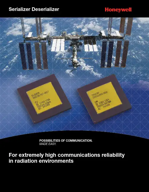
MADE EASY.Honeywell’s responseHoneywell responds to these challenges with our unsurpassed reliability for Gigabit Data Communications and Networks in Space Applications.For both board level packaged parts and macrocells for Application Specific Integrated Circuits (ASICs), Honeywell Serializer Deserializers (SERDES) are designed for extremely highcommunications re liability in radiation environments. SERDES have provencompatibility with communication protocols including Serial Rapid IO, Gigabit Ethernet, and Fibre Channel. SERDES are alsodesigned for direct point to point links and have been demonstrated to be compatible with other industry SERDES products and field-programmable gate array (FPGA) platforms. Serial communications with higher data rates reduce power, wires and weight over existing solutions.HX5000 ASICs and Structured Array with SERDESSERDES can be implemented in HX5000 Standard Cell ASICs and are integrated into the HX5SA13 Structured Array to enable a number of high bandwidth communication solutions. This can range from high speed point-to-point links,to the creation of networks with switches and endpoints.HX5SA13 Structured Array with SERDESThe HX5SA 13 Structured Array contains 16 lanes of SERDES. They are configured as two groups of 8 lanes so there are two separate PLLs and Clock Management Units (CMU).Serializer DeserializerFeatureHXSRD01 TrivorHXSRD02 Slider Number of SERDES lanes Quad Redundant SERDES (8 lanes)4 LanesCommunication Protocol Gigabit Ethernet and Fibre Channel Protocol Serial Rapid IO protocol and protocol bypass Parallel Interface 8/10 bit parallel interface, 2.5V SSTL216/20 bit parallel interface, 2.5V SSTL2Package (pin count)468 CGA Package467 CGA PackageSERDES Benefits■Internet data rates: Rates of 1.0 to 3.125 Gb/s per channel supporting multiple standards■QML V Qualified: First SERDES Qualified Manufacturers List (QML) V Qualified product in 2008■Reliable in radiationenvironments: Low jitter phase-locked loop (PLL) and Transmitter, exceptional Receiver sensitivity, and a SERDES that continues to perform in SEE environments (no PLL unlock, no lanes down, no latchup)■Flexible: SERDES areprogrammable for peak data throughput and the lowest power consumptionStandard ProductsThere are two standard products, the HXSRD01 and HXSRD02, which share a common SERDES physical layer but support slightly different applications, including communication protocols, and slightly different parallel interfaces. Below is a list of the key, unique features of the two products; Select the appropriate product that will meet your system requirements.The control and operation of the two parts share many common items, including control for optimizing performance:■Data Rate of 1.0 to 3.125Gb/s■4 Lane XAUI capability for 10Gb/s operation■1.8V core power supply, 2.5V parallel interface power supply■Independent Lane Control including on/off control for minimal power consumption ■Programmable Tx Output Amplitude and Pre-Emphasis ■Programmable Rx Equalization and Loss-of-Signal ■Integrated 8b10b encoder and decoder ■Integrated Clock and Data Recovery ■Package size and technology ■-55°C to +125°CIndustry challengesThe industry continues to increase requirements for faster and better data communications in space environments. From point-to-point sensor applications to networking an entire satellite, reliable communications with high bandwidth are imperative. Performance, with lower power consumption and 10 times faster than existing technology, fewer wires and less weight is also an expectation.2HXSRD01 Trivor Block DiagramHXSRD02 Slider Block Diagram3RXP[3:0]RXN[3:0]TXP[3:0]TXN[3:0]RXP[3:0]RXN[3:0]TXP[3:0]TXN[3:0]JTAG Logic MDC/MDIO Logic DFT LogicGbE andFiber Channel LogicParallel InterfaceSDR/DDR 8/10-BitRX Interface 8b or 10b * 4TX Interface 8b or 10b * 4MUXPort B 4 Channel SERDESPort A 4 Channel SERDESMDC/MDIO Logic4Channel SERDESRXP[3:0]RXN[3:0]TXP[3:0]TXN[3:0]JTAG LogicSerial Rapid IO PCS Logic (Mercury)RX Interface 16b or 20b * 4TX Interface 16b or 20b * 4DFT LogicInterfaceand Bypass LogicParallel InterfaceSDR/DDR 16/20-Bit MUXBoth 4 lane and 8 lanes HX5000 SERDESmacrocells can be instantiated with tocreate systems with 32 – 40 lanes (powerdissipation can become a limiting factor).The interface to the core logic includesspecialized high speed parallel interfacelogic and Built in Self-Test (BIST) logic.An ASIC provides the flexibility for lowoverhead communication links likepoint to point. In these systems, a fullcommunication networking protocolmay not be necessary and the customercan implement their application specificprotocol in the ASIC logic.HX5000 ASICs4BIST10b to20bLogicHoneywellSERDESInterface(RTL)Customer Logic,Honeywell IP BlocksExternal IP (RTL)Clock &DataRecoverySERDESPLLMacrocellRXTXDe-SerializerSerializerMultiport Switches and Endpoints are common in communication network applications and a more direct “transmitter to receiver” configuration is used for applications like image sensors data processing.Possible Network Implementation(for illustration purposes only)5SERDES LITE Hard Macro sRIO PCS IP ,DIFTSERDES LITE Hard Macro sRIOPCS IP ,DIFTsRIO PCS IP ,DIFTSERDES LITE Hard MacroSERDES LITE Hard MacrosRIO PCS IP ,DIFTS E R D E S L I T E H a r d M a c r o s R I O P C S I P ,D I F TMercury sRIO Switch Soft Macro S E R D E S L I T E H a r d M a c r o s R I O P C S I P ,D I F TMercury sRIOEndpoint IPsRIO EndpointImplemented with HX5SA13Structured Array with SERDES (up to 16 lanes)sRIO EndpointImplemented with HX5000 ASICsRIO EndpointImplemented with a HXSRD02 Slider8-Port sRIO SwitchImplemented with HX5000 ASICMercury sRIO Endpoint IPHXSRD02 Slider Std ProductProcessing Chip with Mercury sRIOEndpoint IPCharacterization and QualificationThe SERDES went through an extensive characterization and qualification process leading to being QML V qualified in 2008. A summary of key performance parameters is summarized below.Independent Functional VerificationThe HXSRD01 Trivor was functionality validated with the industry standards 1G Ethernet, XAUI 10G Ethernet, 1G and 2G and XAUI 10G Fibre Channel at the University of New Hampshire Inter-Operability Lab.Bit Error Ratio and Jitter TestingVerification of Bit Error Ratio (BER) and Jitter over temperature, voltage and data rate demonstrated BER much lower than 1E-12 and a jitter tolerance of better than 0.7UI eye closure.Robust PerformanceOne benefit of the Silicon on Insulator Complementary metal-oxide-semiconductor (SOI CMOS) technology is the low noise process. The transistors are isolated from the bulk silicon substrate which minimizes cross-circuit signal coupling. This leads to a SERDES Transmitter with very low jitter. Shown below is the transmitter output at 3.125Gb/s, 1.7V , 125C, and 100 foot coaxial cable.High Sensitivity SERDES ReceiverThe Receiver is capable of receiving data and delivering a Bit Error Ratio (BER) ********************************/swithaneyethatis~85%closed (shown below).Tested Performance6Radiation Performance SummaryDesigned for the space applications, the SERDES communication is reliable even in strong heavy ion and proton environments.Parameter Limites Units Conditions Total Dose≥1X10⁶rads(Si)Transient Dose Rate Upset ≥1X10¹⁰rads(Si)/s Pulse width = 20 ns Transient Dose Rate Survivability ≥1X10¹²rads(Si)/sPulse width = 20 nsBit Error Rate (s)Heavy Ion Proton≥1X10-12≥1X10-12Bit Upsets/Bits Sent Geosynchronous orbit during solar minimum non-flare conditons behind 100mil Aluminum shieldNeuton Fluence≥1X10⁶N/cm 21MeV equivalent energy, Unbiased, T A =25°C1. Device will not latch up due to any of the specific radiation exposure conditions.2. The Bit Error Ratio (BER) is defined as the number of but errors per bits sent due to ion-induced single event upsets.The SERDES will continue to perform in single event effects environments.• No phase-locked loop unlock • No lanes down • No latchup7******************************10000。

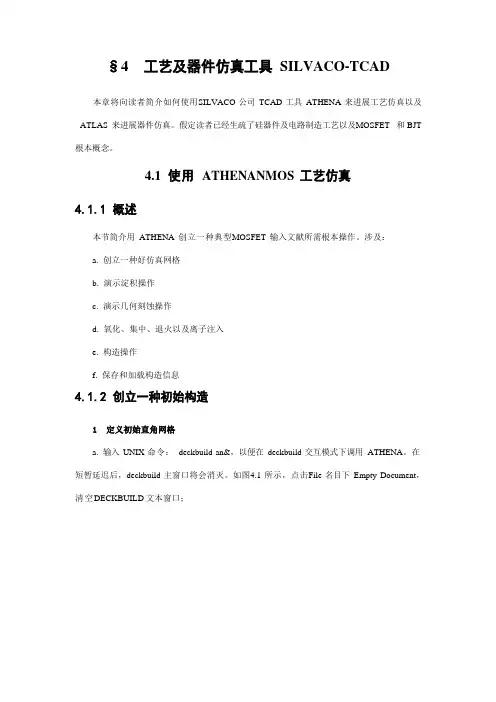
§4 工艺及器件仿真工具SILVACO-TCAD 本章将向读者简介如何使用SILVACO 公司TCAD 工具ATHENA 来进展工艺仿真以及ATLAS 来进展器件仿真。
假定读者已经生疏了硅器件及电路制造工艺以及MOSFET 和BJT 根本概念。
4.1使用ATHENANMOS 工艺仿真4.1.1概述本节简介用ATHENA 创立一种典型MOSFET 输入文献所需根本操作。
涉及:a.创立一种好仿真网格b.演示淀积操作c.演示几何刻蚀操作d.氧化、集中、退火以及离子注入e.构造操作f.保存和加载构造信息4.1.2创立一种初始构造1定义初始直角网格a.输入UNIX 命令:deckbuild-an&,以便在deckbuild 交互模式下调用ATHENA。
在短暂延迟后,deckbuild 主窗口将会消灭。
如图4.1 所示,点击File 名目下Empty Document,清空DECKBUILD 文本窗口;图 4.1 清空文本窗口b.在如图4.2 所示文本窗口中键入语句go Athena ;图 4.2 以“go athena”开头接下来要明确网格。
网格中结点数对仿真精准度和所需时间有着直接影响。
仿真构造中存在离子注入或者形成PN 结区域应当划分更加细致网格。
c.为了定义网格,选取Mesh Define 菜单项,如图4.3 所示。
下面将以在0.6μm×0.8μm 方形区域内创立非均匀网格为例简介网格定义方法。
图 4.3 调用 ATHENA 网格定义菜单2 在0.6μm×0.8μm方形区域内创立非均匀网格a.在网格定义菜单中,Direction〔方向〕栏缺省为X;点击Location〔位置〕栏并输入值0;点击Spacing〔间隔〕栏并输入值0.1;b.在Comment〔注释〕栏,键入“Non-Uniform Grid(0.6um x 0.8um)”,如图4.4 所示;c.点击insert 键,参数将会出当前滚动条菜单中;图4.4定义网格参数图 4.5 点击Insert 键后d.连续插入X 方向网格线,将其次和第三条X 方向网格线分别设为0.2 和0.6,间距均为0.01。

Data SheetCisco S-Class 40GBASE QSFP ModulesProduct OverviewThe Cisco® 40GBASE QSFP (Quad Small Form-Factor Pluggable) portfolio (shown in Figure 1; more details in Table 1) offers customers high-density and low-power 40 Gigabit Ethernet connectivity options for data center, high-performance computing networks, enterprise core, and distribution layers applications.Figure 1. Cisco 40GBASE QSFP ModulesFeatures and Benefits●Hot-swappable input/output device that plugs in to a 40 Gigabit Ethernet Cisco QSFP port●Commercial Temperature (0 to 70°C) only●Interoperable with other IEEE-compliant 40GBASE interfaces where applicable●Cisco quality identification (ID) feature that enables a Cisco platform to identify - optics supported byCisco technology●High-speed electrical interface compliant to the IEEE 802.3ba standard only●1-year limited warrantyTable 1. Cisco S-Class QSFP40G PortfolioCisco QSFP-40G-SR4-SThe Cisco 40GBASE-SR4 QSFP module supports link lengths of 100 and 150 meters, respectively, on laser-optimized OM3 and OM4 multimode fibers. It primarily enables high-bandwidth 40G optical links over 12-fiber parallel fiber terminated with MPO/MTP multifiber connectors. Cisco QSFP-40G-SR4-S is optimized to guarantee interoperability with any IEEE-compliant 40GBase-SR4 module.Cisco QSFP-40G-LR4-SThe Cisco 40GBASE-LR4 QSFP module supports link lengths of up to 10 kilometer over a standard pair of G.652 single-mode fiber with duplex LC connectors. The QSFP-40G-LR4-S module supports 40GBase Ethernet rate only. The 40 Gigabit Ethernet signal is carried over four wavelengths. Multiplexing and demultiplexing of the four wavelengths are managed in the device.Technical SpecificationsFollowing are the technical specifications for platform support, and connectors and cabling.Platform SupportCisco QSFP modules are supported on Cisco switches. For more details, refer to the document “Cisco 40 Gigabit Ethernet Transceiver Modules Compatibility Matrix.”Connectors and CablingSee Table 2 for connector type information and cabling specifications for each QSFP product.Note: Only connections with patch cords with PC or ultra-physical contact (UPC) connectors are supported. Patch cords with angled physical contact (APC) connectors are not supported. All cables and cable assemblies used must be compliant with the standards specified in the standards section of this data sheet.Table 2. QSFP Port Cabling Specifications* 1 Minimum cabling distance is 0.5 meters for -SR4 and -CSR4 modules and 2 meters for -LR4 according to the IEEE 802.3 standard.* 2 Considered an engineered link with maximum 1 decibel loss budget.* 3 Specified at transmission wavelength.Table 3 shows the key optical characteristics for the Cisco QSFP modules.Table 3. Optical Characteristics*5 Transmitter and receiver power is average, unless specified.DimensionsMaximum outer dimensions for the Cisco QSFP connector module are (H x W x D) 13.5 x 18.4 x 72.4 millimeters. Cisco QSFP connector module typically weigh 100 grams or less.Environmental ConditionsOperating temperature range:●Commercial temperature range: 0 to 70°C (32 to 158°F).●Storage temperature range: -40 to 85°C (-40 to 185°F).Warranty●Standard warranty: 1 year.●Extended warranty (optional): Cisco QSFP modules can be covered in a Cisco SMARTnet® Service supportcontract for the Cisco platform chassis.Ordering InformationTable 4 provides the ordering information for Cisco SFP+ modules and related cables.Table 4. Ordering InformationRegulatory and Standards ComplianceFollowing is information about complying with standards and safety regulations.Standards:●GR-20-CORE: Generic requirements for optical fiber and optical fiber cable●GR-326-CORE: Generic requirements for single-mode optical connectors and jumper assemblies●GR-1435-CORE: Generic requirements for multifiber optical connectors●IEEE 802.3ba (-SR4, -LR4)●QSFP+ MSA SFF-8436●SFP+ MSA SFF-8431 and -8461●RoHS 6Safety:●Laser Class 1M per IEC60825-1 and CFR 21 Section 1040For other QSFP 40 gigabit modules and cables, refer to the following link:/c/en/us/products/collateral/switches/nexus-9000-series-switches/datasheet-c78-730160.html.Additional InformationFor more information about Cisco 40GBASE QSFP optics and copper modules, contact your sales representative or visit /en/US/products/hw/modules/ps5455/prod_module_series_home.html.。
ASIC设计工程师岗位职责ASIC设计工程师职位描述:1. 理解MAC层调度方法;2. 负责MAC层架构设计和RTL实现;3. 负责MAC和SOC以及物理层接口设计;4. 负责MAC 层FPGA验证;5. 协作MAC层整体的前端综合和后端timing signoff;6. 协作供应MAC驱动程序;7. MAC层相关模块的优化和维护;任职要求:1. 计算机或电子类专业本科及以上学历,1年以上工作阅历;1. 熟识ARM总线协议;2. 熟识WiFi/BlueTooth/NBIoT/ Ethernet 至少一种MAC层协议;3. 良好的算法理解力量;4. 熟识芯片ASIC前端设计流程;5. 娴熟的verilog/C/C++/matlab/Perl 等编程力量;6. 有胜利流片工程阅历者优先; 1. 理解物理层算法以及协作物理层算法研发;2. 负责物理层算法的RTL 实现;3. 设计物理层微架构;4. 评估物理层算法实现后的的性能;5. 负责相关模块的模块级别验证工作;6. 负责相关模块的FPGA原型验证工作;7. 协作相关模块的前端综合和后端timing signoff;8. 协作底层驱开工程师完善相关模块的驱动;9. 物理层相关模块的优化和维护;任职要求:1. 计算机或通信类专业本科及以上学历,1年以上工作阅历;2. 把握信号处理算法;3. 熟识WiFi/BlueTooth/NBIoT/Ethernet/3G/4G/5G 至少一种物理层算法优先;4. 良好的算法理解力量;5. 熟识芯片ASIC前端设计流程;6. 娴熟的verilog/C/C++/matlab/Perl 等编程力量;7.有胜利流片工程阅历者优先; 职位描述:1. 理解MAC层调度方法;2. 负责MAC层架构设计和RTL实现;3. 负责MAC和SOC以及物理层接口设计;4. 负责MAC 层FPGA验证;5. 协作MAC层整体的前端综合和后端timing signoff;6. 协作供应MAC驱动程序;7. MAC层相关模块的优化和维护;任职要求:1. 计算机或电子类专业本科及以上学历,1年以上工作阅历;1. 熟识ARM总线协议;2. 熟识WiFi/BlueTooth/NBIoT/ Ethernet 至少一种MAC层协议;3. 良好的算法理解力量;4. 熟识芯片ASIC前端设计流程;5. 娴熟的verilog/C/C++/matlab/Perl 等编程力量;6. 有胜利流片工程阅历者优先;篇2:工程师设计岗位职责EPB算法设计与验证工程师上海汇众上海汇众汽车制造有限公司,上海汇众,汇众招聘岗位: EPB算法设计与验证工程师工作地点: 上海市浦东南路1493号数量: 2人学历要求: 硕士及以上学历专业要求: 车辆工程、掌握工程或相关专业英语力量: 英语CET6以上经历要求: 有3年以上底盘电控产品开发经受性别要求: 不限年龄要求: 不限经验要求: 3年以上底盘电控产品的掌握算法的设计验证阅历其他要求: 喜爱这个行业、勤学肯干,具有团队协作精神工作职责:1)依据电子驻车系统(EPB)算法代码进展掌握算法验证工作;2)利用相关的工具,如Tessy,QAC,Polyspace等进展软件单元测试;3)编写算法软件单元测试用例;4)撰写掌握算法软件验证相关的报告和文档;5)熟识软件释放流程,管控软件公布质量。
asic 工程师手册
ASIC(Application-Specific Integrated Circuit)工程师手册是一个非常专业的技术指南,用于指导ASIC工程师进行集成电路设计、验证、测试和实现。
以下是一个可能的ASIC工程师手册的内容大纲:
第一章:概述
ASIC简介
ASIC的应用领域
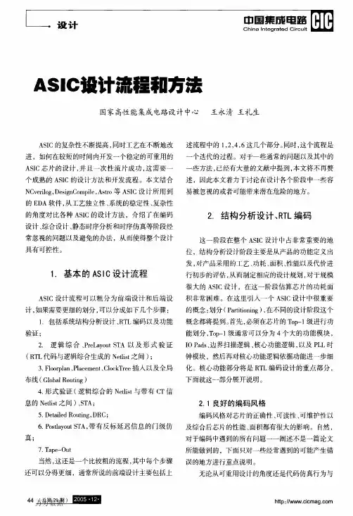
ASIC的设计流程
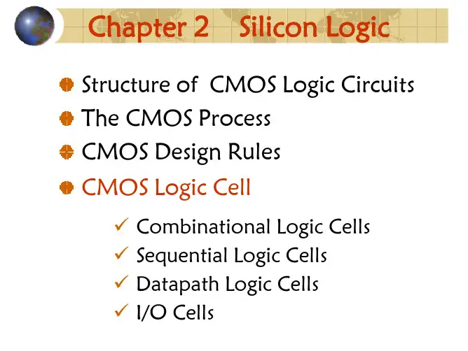
第二章:集成电路设计基础
集成电路的基本构成
集成电路设计工具简介
集成电路设计语言(如Verilog和VHDL)
第三章:ASIC设计流程
需求分析
规格说明
架构设计
逻辑设计
物理设计
布线与布局
测试与验证
第四章:ASIC验证方法
仿真验证
形式验证
静态时序分析(STA)
物理验证(DRC/LVS)
第五章:ASIC测试技术
测试策略与测试计划
测试向量生成
内建自测试(BIST)
故障模拟与故障覆盖率分析
第六章:ASIC实现与版图绘制
工艺选择与参数提取
设计版图生成与后端物理合成
DFM(可制造性设计)考虑因素
最终版图检查与验证
第七章:ASIC制程与封装
制程技术简介
封装技术与材料选择
制程与封装测试方法
第八章:ASIC可靠性与可靠性分析
ASIC可靠性概述
环境应力对ASIC的影响
ASIC可靠性分析方法与工具介绍(如加速寿命测试、失效模式和效应分析)第九章:ASIC设计案例研究
案例一:数字信号处理(DSP)ASIC设计实例案例二:通信系统ASIC设计实例
案例三:高性能计算(HPC)ASIC设计实例。