PDS-770数字式发电机保护装置说明书
- 格式:pdf
- 大小:697.12 KB
- 文档页数:61
产品使用前请仔细阅读本说明书WTGB2000微机综合保护装置说明书使用说明书安装使用前请详细阅读本使用说明书淮南万泰荣博照明科技有限公司出版日期2014-01-11警告◆严格遵照执行国家及电力行业相关安全规程。
工作在高电压环境下,应严肃认真对待,以避免人身伤害或设备损坏。
◆在操作中不应接触电路,可能会有致命的电压、电流。
◆在拆卸装置面板后,应避免触及电路。
◆在正常运行期间,严禁断开、连接与端子相连的导线或连接件,可能会有致命的危险电压、电流,也可能会中断设备的运行,损坏端子及测量电路。
小心◆不得将装置与带电导线相连,这可能会使装置内部电路受到损坏。
◆在移动装置的板件时,应使用经过验证的防静电袋。
在对板件进行操作或处理时,应使用导电腕环套与保护地相连,并在适当的防静电表面操作。
静电可能会引起芯片损坏。
!注意!◆装置上电使用前请仔细阅读说明书,参照说明书对装置进行操作、定值运行参数整定和测试。
如有随机资料,相关部分以资料为准。
◆装置上电前,应明确连线与正确示图相一致。
通电前注意事项⏹核对装置箱体上的出厂标签与出厂检验报告,并确认与定货一致。
⏹检查装置外壳是否有明显的损伤和变形。
⏹检查各插件插拔接触是否可靠。
⏹装置外壳是否可靠接地。
⏹装置供电电源为交流或直流220V。
⏹检查输入装置的交流量各相序及极性应正确无误。
1一、概述WTGB2000微机综合保护装置(以下简称产品)是功能先进的微机型综合保护装置,主要应用于10kV及以下电压等级的高压开关柜保护中,可对进线、电容器、电动机、厂用变等设备进行保护。
1.1保护功能配置见表1。
产品根据保护对象的不同,设有四种保护模式(可在“设置”菜单的“保护对象”一栏设定),分别适用于线路、电容器、电动机、厂变不同保护对象。
序号功能名称线路电容器电动机厂用变1 两段式电流保护√√√√2 过流反时限保护√√3 负序电流保护√4 过负荷保护√√√5 三相一次重合闸√6 后加速保护√7 过电压保护√√8 低电压保护√√√√9 零序电流保护√√√√10 零序反时限保护√11 不平衡电流保护√12 低频减载√13 启动时间过长√14 过热保护√15 控制回路异常告警√√√√16 弹簧未储能告警√√√√17 TV断线检测√√√√18 非电量保护Ⅰ√19 非电量保护Ⅱ√20 非电量保护Ⅲ√21 重瓦斯保护√22 高温保护√23 遥信、遥控功能√√√√24 遥测√√√√表11.2 产品主要特点a.本产品为微机保护装置,其元器件采用工业品,稳定性、可靠性高,可以在高压开关柜等恶劣的环境中工作;宽范围使用环境温度-25℃~+55℃。
国电南自PDS 2000数字化防误操作系统装置使用说明书国电南京自动化股份有限公司GUODIAN NANJING AUTOMATION CO.,LTD安全声明1. 说明安全声明与相关的装置文件构成了安全操作、调试与测试的完整信息。
在对装置作任何操作之前,使用人员必须熟悉本安全声明的内容和装置铭牌的额定参数。
2. 健康和安全装置的正常和安全运行,依赖于恰当的运输、搬运和正确的贮存、安装和调试,以及细心的操作、维护和维修。
因此,只有合格人员才可操作或在装置上工作。
合格人员是指:——熟悉装置的安装、调试和运行及所接入的系统的人员;——能够按照认可的安全工程惯例执行操作,并经授权可对装置进行带电、掉电、隔离、接地操作的人员;——经过设备安全使用培训的人员;装置的安装、调试和运行由装置文件提供了说明,但手册不能涵盖所有细节,在出现问题或特殊情况时,未经正确授权不得采取行动。
3. 设备的安装、调试和维护警告!a) 装置的安装调试应由专业人员进行或指导;b) 装置上电使用前请仔细阅读说明书。
应遵照国家和电力行业相关规程,并参照说明书对装置进行操作、调整和测试。
如有随机材料,相关部分以资料为准;c) 装置施加的额定操作电压应该与铭牌上标记的一致;d) 严禁无防护措施触摸电子器件,严禁带电插拔模件;e) 在拆卸开装置面板后,应避免触及电路,装置包含电子电路,如果遭受静电,可能会受到损坏;f) 不管运行条件如何,必须将装置与保护地相连。
这也适用于一些特殊的场合,如在台桌上测试演示及离线配置。
不经恰当接地操作装置,可能会损坏装置,也可能会发生事故引起伤害;g) 不得将装置与带电导线相连,这可能会导致装置内部电路损坏;h) 在安装调试装置过程中,如果碰触装置或其连线要小心,以免受到电击。
*技术支持电话:(025)52393607传真:(025)52393606* 本说明书可能会修改,请注意核对实际产品与说明书版本是否相符。
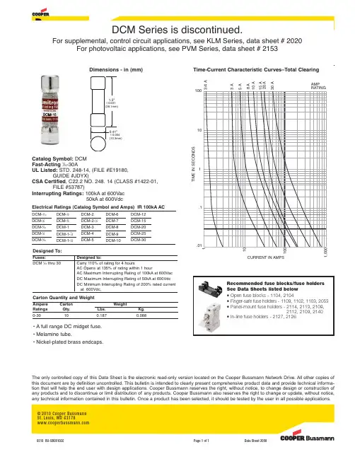
Electrical Ratings (Catalog Symbol and Amps) IR 100kA ACFast-Acting 13⁄32˝ x 1 1⁄2˝ (10x38mm) Midget Fuses, 600Vac/dc, 1⁄10–30ADCM SeriesDimensions - in (mm)DCM-1⁄10DCM-1⁄8DCM-2⁄10DCM-1⁄4DCM-3⁄10DCM-1⁄2DCM-3⁄4DCM-1DCM-1-1⁄4DCM-1-1⁄2DCM-6DCM-7DCM-8DCM-9DCM-10DCM-12DCM-15DCM-20DCM-25DCM-30DCM-2DCM-2-1⁄2DCM-3DCM-4DCM-5•A full range DC midget fuse. •Melamine tube.•Nickel-plated brass endcaps.Designed To:Fuses:Designed to:DCM 1⁄10thru 30Carry 110% of rating for 4 hoursAC Opens at 135% of rating within 1 hourAC Maximum Interrupting Rating of 100kA at 600Vac DC Maximum Interrupting Rating of 50kA at 600Vdc DC Minimum Interrupting Rating of 200% rated current at 600Vdc,Catalog Symbol:DCM Fast-Acting 1⁄10-30AUL Listed:STD. 248-14, (FILE #E19180,GUIDE #JDYX)CSA Certified , C22.2 NO. 248. 14 (CLASS #1422-01,FILE #53787)Interrupting Ratings:100kA at 600Vac50kA at 600VdcCarton Quantity and WeightAmpere Carton WeightRatings Qty.Lbs.Kg.0-30100.1870.088Recommended fuse blocks/fuse holders See Data Sheets listed below • Open fuse blocks - 1104, 2104• Finger-safe fuse holders - 1109, 1102, 1103, 2053• Panel-mount fuse holders - 2114, 2113, 2108,2112, 2109, 2140• In-line fuse holders - 2127, 2126110100CURRENT IN AMPS.01.1110100AMPRATING3/4 A 15 A 10 A20 A30 A8 A 5 A3 A1,000T I M E I N S E C O N D STime-Current Characteristic Curves–Total Clearing©2010 Cooper Bussmann St.Louis,MO 631780310 BU-SB091066Page 1 of 1Data Sheet 2038The only controlled copy of this Data Sheet is the electronic read-only version located on the Cooper Bussmann Network Drive.All other copies of this document are by definition uncontrolled.This bulletin is intended to clearly present comprehensive product data and provide technical informa-tion that will help the end user with design applications.Cooper Bussmann reserves the right,without notice,to change design or construction of any products and to discontinue or limit distribution of any products.Cooper Bussmann also reserves the right to change or update,without notice,any technical information contained in this bulletin.Once a product has been selected,it should be tested by the user in all possible applications.1.5"ע0.031(38.1mm)0.41"ע0.004(10.3mm)DCM Series is discontinued.For supplemental, control circuit applications, see KLM Series, data sheet # 2020For photovoltaic applications, see PVM Series, data sheet # 2153。
PDS-770数字式发电机保护装置说明书(040812) PDS-770数字式发电机保护装置说明书(040812)1.引言1.1 目的1.2 范围1.3 定义2.产品概述2.1 产品特点2.2 技术规格2.3 硬件结构2.4 软件功能3.安装与调试3.1 安装要求3.2 安装步骤3.3 调试步骤3.4 注意事项4.功能说明4.1 电压保护4.1.1 过欠压保护 4.1.2 断相保护 4.2 频率保护4.2.1 过频保护 4.2.2 欠频保护 4.3 电流保护4.3.1 过流保护 4.3.2 地电流保护 4.4 功率保护4.4.1 过功率保护 4.4.2 欠功率保护 4.5 温度保护4.5.1 过温保护4.5.2 欠温保护5.操作与设置5.1 操作界面5.2 参数设置5.3 保护参数设置5.4 报警与事件记录5.5 定值修改6.维护与维修6.1 日常维护6.2 故障诊断与维修6.3 零部件更换6.4 装置校准7.附录7.1 附加设备接口7.2 故障码及处理方法7.3 技术支持与联系方式附件:1.PDS-770数字式发电机保护装置安装示意图2.PDS-770数字式发电机保护装置接口说明3.PDS-770数字式发电机保护装置维护手册法律名词及注释:1.保护装置:指用于电力设备保护的装置,可对电流、电压、频率、功率等进行监测和保护。
2.电流保护:利用电流传感器监测电流,当电流超过设定值时,触发保护装置进行相应的保护动作。
3.电压保护:利用电压传感器监测电压,当电压超过或低于设定值时,触发保护装置进行相应的保护动作。
4.频率保护:利用频率传感器监测电网频率,当频率超过或低于设定值时,触发保护装置进行相应的保护动作。
5.功率保护:通过计算电压和电流以及功率因数来监测和保护发电机的功率输出,以防止过载和过功率。
6.温度保护:通过温度传感器监测发电机的温度,当温度超过设定值时,触发保护装置进行相应的保护动作。
小电厂10kV电缆按热稳定校验选择截面一、引言随着社会工业化的发展,电力系统的重要也与日俱增。
而电缆是电力系统中的“血管”,它的安全可靠关系着整个电力工程的运行安全与稳定。
同时,电缆在电力工程的直接建材费中占比也非常高。
所以选择一个科学、合理的电缆就有关重要。
为了保证供电系统的安全、可靠、优质、经济地运行,选择导体截面时,除满足工作电压的要求外,一般还要满足发热条件:电流通过电缆时要产生电能损耗,使导体发热升温,严重时会损坏绝缘层甚至引起火灾。
但是当前的很多设计人员,在设计选型时,往往根据计算电流,容许压降等技术条件选择电缆的截面,却往往忽视了电缆的动稳定和热稳定校验。
所以在35kV以下的电缆中,动稳定基本都能满足要求,而热稳定如果不进行校验,往往就不满足要求,造成停电甚至发生火灾。
所以本文着重探讨电缆的热稳定校验。
二、设计的依据根据DL/T5222-2005《导体和电器选择设计技术规定》5.0.2规定:选用导体的长期允许电流不得小于该回路的持续工作电流。
对于断路器、隔离开关、组合电器、封闭式组合电器、金属封闭开关设备、负荷开关、高压接触器等长期工作制电器,在选择其额定电流时,应满足各种可能运行方式下回路持续工作电流的要求。
根据GB50217-2007《电力工程电缆设计规范》(以下简称《电缆规范》)3.7.7规定:对非熔断器保护回路,应按满足短路热稳定条件确定电缆导体允许最小截面,并应按照本规范附录E的规定计算。
规范的附录中我们可以知道在固定绝缘电缆的导体允许最小截面,按下面公式:210×≥CQS(E.1.1-1))20(1)20(1ln1−+−+=pmkJqCθαθαραη(E.1.1-2)200))((HpHpIIθθθθ−+=(E.1.1-3)根据公司E.1.1-1可知,电缆的最小截面跟发热量Q和热稳定系数C有关。
而热稳定系数因温度、单位体积热容量、电阻温度系数、电阻系数、校正系数等众多参数的影响,计算复杂。
PDS-760系列数字式保护测控装置使用手册(版本号:V3.00)南京南自机电自动化有限公司二○○六年十二月*版权所有:南京南自机电自动化有限公司*注:本公司保留对说明书的修改权,恕不另行通知。
关注最新版本,请登录查询。
在装置安装和调试过程前,请仔细阅读本手册相关章节(第三章和第七章目录目录一、概述 (4)1.1. 产品适用范围 (4)1.2. 产品特点 (4)1.3.产品功能配置 (5)二、主要参数和技术指标............................................................ 错误!未定义书签。
2.1. 工作电源..........................................................................................错误!未定义书签。
2.2. 工作频率..........................................................................................错误!未定义书签。
2.3. 交流电流输入(CT)......................................................................错误!未定义书签。
2.4. 交流电压输入(PT)..........................................................................错误!未定义书签。
2.5. 开关量输入......................................................................................错误!未定义书签。
2.6. 接点输出..........................................................................................错误!未定义书签。
第一章概述一、设计依据本工程依据甲方设计委托书、甲方提供资料进行施工设计。
二、建设规模建设介休煜业选煤10kV配电所1座;容量为7525kVA,采用单电源供电。
10kV进线1回,出线6回。
建设相应的二次及电源侧部分,0.4kV及土建部分不做设计。
第二章电气一次部分一、接线及运行方式10kV采用单电源供电,由110kV北辛武变电站10kV新建专线供电,线路长1.5kM,10kV母线采用单母线分段接线方式。
计量点设在用户侧。
10kV进线装1套组合计量装置。
二、无功功率补偿本站装设并联电容器作为无功损耗补偿装置,分别在10kV母线上集中补偿和低压侧补偿,10kV母线上补偿容量为600kVar。
三、设备选择本配电室由110kV北辛武变电站10kV新建专线供电时,短路电流较大,线路长1.5km。
2009年北辛武站10kV系统短路容量为171kVA,经计算本配电室10KV三相短路电流为:4.9kA。
根据正常条件选择,按短路条件校验,本站设备选择如下:10kV开关柜:KYN28A-12(Z)10kV断路器:VBG-12/630-25型户内真空断路器,附弹簧机构10kV电流互感器:LZZBJ9-12型0.5/10P15级上述设备均安装于KYN28A-12(Z)开关柜内。
四、电气平面布置及配电装置本期工程新建10kV开关柜11面,分别为10kV进线柜1面、计量柜1面、PT柜1面、补偿柜2面、出线柜6面,均安装在10kV配电室内,单列布置。
开关柜采用KYN28A-12(Z)型开关柜,10kV进线采用10kV电压等级的MYJV22-3×240交联聚乙稀电力电缆,10kV出线采用10kV电压等级的3芯交联聚乙稀电力电缆,采用走电缆沟方式敷设。
配电所内所有的门均需向外开启。
五、过电压保护为防止内部过电压,在10kV进线侧、母线及出线上分别装设一组氧化锌避雷器。
六、防雷及接地1、防雷配电室由厂区内的避雷针保护,本次不做设计。

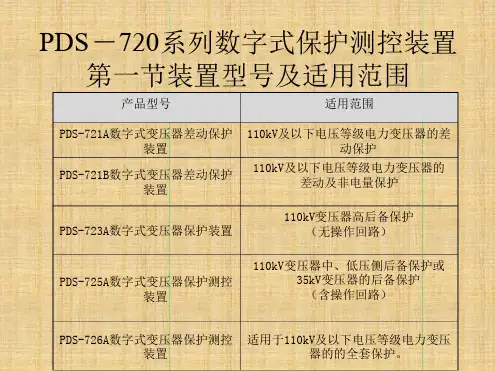
PDS-7000厂站自动化系统PDS-770系列数字式发电机保护装置技术说明书(版本号:V2.00)南京南自机电自动化有限公司二○○五年六月一、概述1.产品型号及适用范围PDS-770系列数字式发电机保护是以32位微处理器为核心的数字式发电机保护装置。
它适用于125MW及以下容量的发电机或发电机变压器组保护,能满足不同容量、电压等级的发电机或发电机变压器组保护功能的需要。
产品型号及适用范围见下表2.产品特点PDS-7000厂站自动化系统是我公司在第一代变电站自动化系统WBX-35基础上自行开发、拥有完全知识产权的第二代产品。
WBX-35系统自1999年通过部级鉴定并投入系统运行以来,已累计投运近5000套微机保护装置,几百个变电站使用了WBX-35变电站综自系统。
产品广泛应用在电力系统及其他工业领域。
该系统的微机保护装置运行稳定可靠,得到了用户的好评。
为适应新的市场需求,保持公司的产品在技术上的先进性,增强产品的市场竞争力,在总结已投运系统的成功经验及广泛听取用户意见和建议的基础上,开发出了适用于变电站和发电厂的第二代保护及自动装置硬件、软件平台,并在平台的基础上开发出了PDS-700系列保护和自动装置。
本分册所介绍的PDS-770系列数字式发电机保护装置即是该系列保护和自动装置中的发电机和发电机变压器组保护装置部分。
PDS-700系列保护和自动装置相比第一代产品,采用了较多的新技术、新工艺,添加了许多新功能,使之具有更高的可靠性、更广的适用性、更好的使用性及更优的性价比。
具有以下的特点:1.统一硬件平台。
采用功能强大的32位微处理器,并在此基础上构成了第二代保护的通用硬件平台。
PDS -710、PDS-720、PDS-730、PDS-740、PDS-770、PDS-790系列保护和自动装置均采用该通用平台设计。
该硬件平台的特点:1)大资源,配置了大容量的存贮器,包括随机存储器RAM,闪烁存储器FLASH RAM,电可擦存储器EEPRM等。
NSC 554U数字式发电机保护装置说明书南京南自四创电气有限公司20012年6月*本说明书可能会被修改,请注意最新版本资料目次1装置简介 (1)2 装置硬件构成 (2)2.1 交、直流输入模件 (2)2.2 主处理模件 (2)2.3 人机对话模件 (3)2.4 输出及信号模件 (2)3 技术指标 (5)3.1运行环境 (5)3.2 额定参数 (5)3.3 装置技术参数 (5)4 绝缘性能 (6)4.1 绝缘电阻 (6)4.2 介质强度 (6)4.3 冲击电压 (6)4.4 耐湿热性能 (6)4.5 抗电磁干扰性能 (6)4.6 机械性能 (6)5 保护原理 (7)5.1发电机纵差保护 (7)5.2发电机定子接地保护 (9)5.3 发电机过电压保护 (10)5.4 发电机静稳失磁保护 (11)5.5 发电机定时限负序过流保护 (14)5.6 发电机过负荷保护 (15)5.7 发电机叠加直流式转子一点接地保护 (16)5.8 发电机谐波序电压式转子两点接地保护 (17)5.9 发电机频率异常保护 (18)5.10发电机逆功率保护 (19)5.11发电机复合过流(记忆过流)保护 (20)5.12 非电量保护(发电机热工保护、灭磁联跳保护、LCB温度高保护) (21)6 定值清单 (222)7装置背板布置图 (2224)1装置简介NSC 554U发电机保护装置专为小型中型汽轮发电机、水轮发电机、燃气轮发电机等发电机机组设计,且并能满足电厂自动化系统的要求。
保护装置CPU的保护功能配置表功能NSC554U发电机差动保护√发电机过电压保护√发电机失磁保护√发电机复合电压过流保护√发电机频率保护√发电机转子一点接地保护√发电机转子两点接地保护√发电机定子接地保护√发电机逆功率保护√发电机非电量保护√TA、TV断线保护√※注:装置配有一套完整操作回路,无须单独配置发电机出口断路器操作箱;装置的保护出口方式可由定值整定。
M S S er i esM a n ua lm ot o rp r ot e ct o rsCK1-xx contacts must mount flush on the right side of the MS132; these devices are supplementary and not required for use in UL 508 Type E &F applicationsSK4-11 contacts are required for UL 508 Type E applications using types MS4xx; included when purchasing types MS4xx-xxEHKF1-11HK4-11HK1-11 HKS4-20SK1-11 CK1-11 SK4-11AA1-24UA1-24AA4-24AccessoriesFor Types MS116, MS132, MS45x, MS49xM S S e r i e s M a n u a l m o t o rp r o t e c t o r sActuation tablesFor Types MS116, MS132, MS45x, MS49xX = Indicates closed state O = Indicates open stateFor connection diagrams, see page 4.17.1 + I>> indicator window = red.M S S er i e s M a n u a l m o t o r pr o t e c t o r sThe DX495 terminal is included when purchasing type MS49x-xxE devices.PS1-2-0-65PS1-3-1-100S1-M3-25KA450DX495AccessoriesFor Types MS116, MS132, MS45x, MS49xM S S e r i e s M a n u a l m o t o rp r o t e c t o r s 4AccessoriesFor Types MS116, MS132ABB Manual motor protectors can also be connected to the SMISSLINE power distribution bus system, which provides a versatile and flexible means of distributing power to a wide variety ofelectrical devices. For complete system information, see Section 24.The 9 mm wide additional housing is needed when an odd number of combi modules are plugged on the socket; required to fill space into a full module (18 mm).The 9 mm wide additional housing must also be used when a side-mount auxiliary contact isused.SMISSLINE busbar combi modules for types MS116 / MS132 +M S S er i esM a n ua lm ot o rp r ot e ct o rsLocking accessoriesDoor mount kits - Type 12 & IP 65Max. 3 padlocks with bail diameter Ø 4…6.5 mmThrough-door hardware - Types 1, 3R, 12 and IP 64Max. 3 padlocks with bail diameter Ø 5…8 mmFor coded shaft couplers, the “On” position is dependent on the mounting orientation of the MMPMust have handle, shaft coupler and shaft for through-door operation. Drive spindles can replace both shaft coupler and shaft.Enclosures - Type 12 & IP 65Type MS116 devices trip to the “Off” positionMax. 3 padlocks with bail diameter Ø 4…6.5 mmFor UL enclosure type ratings, contact technical support.SA1 SA2DMS132-GMSHD-LY MSHD-LTY1SAM101923R00021SAM101924R00131SAM201920R1000IB132-GAccessoriesFor Types MS116, MS132, MS45x, MS49xM S S e r i e s M a n u a l m o t o rp r o t e c t o r sAccessoriesFor Types MS116, MS132, MS45x, MS49xMS132 + PSR SoftstarterMS132 + AF ContactorBEA16-4BEA16-3M S S er i e s M a n u a l m o t o r pr o t e c t o r sCurrent limitersThe sum of all load currents including inrush currents shall not exceed the maximum permissible load of the S803W.1 Also suitable for Tap Conductor protection.2 Requires the use of a line-side feeder terminal S1-M3-xx; see accessories section.3MCCB interrupting rating must be equal to or greater than the rating of the device.MS132 Short circuit current ratings using S803W current limiters (kA)Catalog numberUL 508 - Motor controllers, manual (NLRV)UL 508 - Combination motor controllers (NKJH)Circuit breakerGroup motor installation 1Self-protected Type E 2Self-protected Type F 2240V 480V600V480Y/ 277V600Y/ 347V480Y/ 277V600Y/ 347VType F contactorsMS132-0.16MCCB, 400Amax.3656565476547AF26…AF38MS132-0.25656565476547AF26…AF38MS132-0.4656565476547AF26…AF38MS132-0.63656565476547AF26…AF38MS132-1.0656565476547AF26…AF38MS132-1.6656565476547AF26…AF38MS132-2.5656565476547AF26…AF38MS132-4.0656565476547AF26…AF38MS132-6.3656565186547AF26…AF38MS132-10656565186547AF26…AF38MS132-12656565-65-AF26…AF38MS132-16656565-65-AF26…AF38MS132-20656565-65-AF26…AF38MS132-25656565-65-AF26…AF38MS132-32656565-65-AF26…AF38S803W-SCL32-SRt i m e [s ]n x I Maximum loadAccessories For Type MS132Rated for use with the type MS132, the S803W current limiters can provide selective coordination for individual downstream SCPDs, and can be utilized in combination up to 65 kA at 600 v ac. For more information, see Section 17 - S800 Series.M S S e r i e s M a n u a l m o t o rp r o t e c t o r sConnection diagramsFor Types MS116, MS132, MS45x, MS49xConnection diagramsAccessories for use with Type MS116, MS132 & MS4xx1 L1 5 L38676I >>I >I D1D2<U C1C2423288423434781321221466568675857787314133434433417755658557675765665858783 L268AA1...AA4...UA1...UA4...HKF1-11HK4-11HK1-11HKS4-11HKF1-20HK4-20HKF1-02HK4-02SK1-11SK4-11SK1-20SK1-02CK1-11SK4-11CK1-20CK1-02M S S er i esM a n ua lm ot o rp r ot e ct o rsMS116UA1AA1SK1HK1CK1CK1HK1HK1SK1HK1S1-M1-25PS1-..-65BS1-3PS1-..-65S1-M2-25MS132S1-M1-25PS1-..-100BS1-3SA13-phase busbar upto 92 A3-phase busbar upto 65 AHKF1General accessory mounting layoutMS116 & MS132M S S e r i e s M a n u a l m o t o rp r o t e c t o r sMain circuit – Utilization characteristics according to IEC/ENShort-circuit breaking capacity and back-up fusesl CS Rated service short-circuit breaking capacity l CU Rated ultimate short-circuit breaking capacity I CC Prospective short-circuit current at installation location Note: Maximum rated current of the back-up fuses if I CC > I CSType230 V AC 400 V AC 440 V AC 500 V AC 690 V AC I CS kAI CU kAgG, aM AI CS kAI CU kAgG, aM AI CS kAI CU kAgG, aM AI CS kAI CU kAgG, aM AI CS kAI CU kAgG, aM AMS116-0.16No back-up fuse required up to I CC = 50 kANo back-up fuse required up to I CC = 30 kAMS116-0.25MS116-0.4MS116-0.63MS116-1.0MS116-1.6MS116-2.51010251010255525MS116-4.0662566252225MS116-6.3666366632240MS116-10666366632250MS116-12 252580252580666366632250MS116-16161680161680666344632263MS116-201015-1015-36-34-22-MS116-251015-1015-36-34-22-MS116-321010-1010-36-34-22-MS116-10: No need for back-up fuse in networks with a prospective current of up to 50 kA at 400 V .MS116-16: No need for back-up fuse in networks with a prospective current of up to 16 kA at 400 V . With an appropriate 80 A type gG fuse the device can be used in a network with a prospective current of up to 100 kA.MS116-32: No need for back-up fuse in networks with a prospective current of up to 15 kA at 400 V .Technical data - IEC/EN MS116M S S er i e s M a n u a l m o t o r pr o t e c t o r s TypeMS116StandardsUL 508, CSA 22.2 No. 14Maximum operational voltage 600 V ACManual motor controller ratings See table "UL 508 – Manual motor controller"Trip rating 125 % FLAMotor ratings Horse powerSee table "Motor rating, three phase"Full load amps (FLA)See table "Motor rating, three phase"Locked rotor amps (LRA)See table "Motor rating, three phase"Motor rating, three phasehp Horse power FLA Full load amps LRALocked rotor ampsType110-120 V AC 220-240 V AC 440-480 V AC 550-600 V AC hpFLALRAhpFLALRAhpFLALRAhpFLALRAMS116-0.16-0.160.96-0.160.96-0.160.96-0.160.96MS116-0.25-0.25 1.5-0.25 1.5-0.25 1.5-0.25 1.5MS116-0.4-0.4 2.4-0.4 2.4-0.4 2.4-0.4 2.4MS116-0.63-0.63 3.78-0.63 3.78-0.63 3.78-0.63 3.78MS116-1.0- 1.0 6.0- 1.0 6.0 1.0 6.01/20.98MS116-1.6- 1.69.6- 1.69.63/4 1.612.53/4 1.310MS116-2.5- 2.515.01/2 2.2201 2.1151-1/2 2.416MS116-4.0- 4.016.01 4.2302 3.4253 3.925.6MS116-6.31/2 4.4401-1/2 6.4403 4.8325 6.136.8MS116-1018.46039.66457.6467-1/2950.8MS116-121-1/2128039.6647-1/21163.5101164.8MS116-16213.6100515.292101481101164.8MS116-20319.2128515.292101481151793MS116-25319.21287-1/22212715211162022116MS116-32530.4184102816220271452527146Technical data - UL/CSA MS1161 Suitable as motor disconnect only when provided with padlock SA1 or SA3...Main circuit – Utilization characteristics according to UL/CSAM S S e r i e s M a n u a l m o t o rp r o t e c t o r sGeneral technical dataMain circuit – Connecting characteristicsTechnical data MS116M S S er i e s M a n u a l m o t o r pr o t e c t o r s Type MS132StandardsIEC/EN 60947–2, IEC/EN 60947-4-1, IEC/EN 60947-1Rated operational voltage U e 690 V AC / 250 V DC Rated frequency DC, 50/60 HzTrip class10 (10A for MS132-0.16)Number of poles 3Duty time100 %Rated impulse withstand voltage U imp 6 kVRated insulation voltage U i 690 V ACRated operational current I eSee ordering details Rated instantaneous short-circuit current setting I i See ordering detailsRated service short-circuit breaking capacity I cs See table "Short-circuit breaking capacity and back-up fuses"Rated ultimate short-circuit breaking capacity I cuSee table "Short-circuit breaking capacity and back-up fuses"Short-circuit breaking capacity and back-up fusesl CS Rated service short-circuit breaking capacity l CU Rated ultimate short-circuit breaking capacity I CC Prospective short-circuit current at installation location Note: Maximum rated current of the back-up fuses if I CC > I CSType230 V AC 400 V AC 440 V AC 500 V AC 690 V AC I CS kAI CU kAgG, aM AI CS kAI CU kAgG, aM AI CS kAI CU kAgG, aM AI CS kAI CU kAgG, aM AI CS kAI CU kAgG, aM AMS132-0.16No back-up fuse required up to I CC = 100 kAMS132-0.25MS132-0.4MS132-0.63MS132-1.0MS132-1.6MS132-2.5MS132-4.02020*2020*33*MS132-6.32020*2020*33*MS132-102020*2020*33*MS132-122020*2020*33*MS132-162020*2020*33*MS132-202020*2020*33*MS132-25505010050501002020*1010*33*MS132-32255012525501252020*1010*33*MS132-16: No need for back-up fuse in networks with a prospective current of up to 100 kA at 400 V .MS132-32: No need for back-up fuse in networks with a prospective current of up to 50 kA at 400 V . With an approbiate 125 A type gG fuse the device can be used in a network with a prospective current of up to 100 kA * not available yetTechnical data - IEC/EN MS132Main circuit – Utilization characteristics according to IEC/ENM S S e r i e s M a n u a l m o t o rp r o t e c t o r sMain circuit – Utilization characteristics according to UL/CSAMotor rating, three phasehp Horse power FLA Full load amps LRALocked rotor ampsType110-120 V AC 220-240 V AC 440-480 V AC 550-600 V AC hpFLALRAhpFLALRAhpFLALRAhpFLALRAMS132-0.16-0.160.96-0.160.96 - 0.160.96 - 0.160.96MS132-0.25-0.25 1.5-0.25 1.5 - 0.25 1.5 - 0.25 1.5MS132-0.4-0.4 2.4-0.4 2.4 - 0.4 2.4 - 0.4 2.4MS132-0.63-0.63 3.78-0.63 3.78 - 0.63 3.78 - 0.63 3.78MS132-1.0- 1.0 6.0- 1.0 6.0 - 1.0 6.0 1/2 1.0 6.0MS132-1.6- 1.69.6- 1.69.6 3/4 1.69.6 3/4 1.69.6MS132-2.5- 2.515.01/2 2.515.01 2.515.0 1-1/2 2.515.0MS132-4.0- 4.024.01 4.024.02 4.024.03 3.926.0MS132-6.31/2 6.337.81-1/2 6.337.83 4.832.056.137.0MS132-103/410.060.039.664.057.646.0 7-1/2 9.051.0MS132-121-1/212.072.039.664.0 7-1/2 11.064.01011.065.0MS132-16216.084.0515.292.01014.081.01011.065.0MS132-20319.2128.0515.292.01014.081.01517.093.0MS132-25319.2128.07-1/222.0127.01521.0116.02022.0116.0MS132-32530.4184.01028.0162.02027.0145.02527.0146.0Technical data - UL/CSA MS1324M SS er i esM an ua lm ot o rp r ot e ct o rsType MS132 Pollution degree3Phase loss sensitive YesAmbient air temperatureOperation Open - compensated without derating-25 ... +60 °COpen-25 ... +70 °CEnclosed (IB132)0 ... +40 °CStorage-50 ... +80 °CAmbient air temperature compensation ContinuousMaximum operating altitude permissible2000 mResistance to shock acc. to IEC 60068-2-2725 g / 11 msResistance to vibrations acc. to IEC 60068-2-6 5 g / 3 ... 150 HzMounting position Position 1-6 (optional for single mounting) Mounting DIN-rail (EN 60715)Group mounting On requestMinimum distance to otherunits same typeHorizontal0 mmVertical150 mmMinimum distance toelectrical conductive boardHorizontal, up to 400 V0 mmHorizontal, up to 690 V> 1.5 mmVertical75 mmDegree of protection Enclosure / terminals IP20Main circuit – Connecting characteristicsTechnical dataMS132General technical dataM S S e r i e s M a n u a l m o t o rp r o t e c t o r sTechnical dataMS116 & MS132 AccessoriesGeneral technical dataTypeUA1AA1Standards IEC/EN 60947-1, UL 508/60947-4-1A, CAN/CSA C22.2 No.14/60947-4-1-07Pick-up value % of Uc ≥ 85≥ 70Drop-out value% of Uc 35…70-Power consumption Pick-upVA 9HoldingVA 3Ambient air temperatureOperation -20…+55 °C Storage-50…+80 °CM S S er i e s M a n u a l m o t o r pr o t e c t o r s Contact utilization characteristics per IECTypeHKF1-xxHK1-xxHK1-20LSK1-xxCK1-xxStandardsIEC/EN 60947-5-1 Rated operational voltage U e250 V AC/690 V AC/250 V DC 600 V DC Conventional free-air thermal current I th 5 A 6 ARated frequency50/60 Hz Rated impulse withstand voltage U imp 6 kVA Rated insulation voltage U i 230 V 690 V Pollution degree3Ambient air temperature Operation -20…+55 °C Storage -50…+80 °C Resistance to shock acc. to IEC 60068-2-2725 g / 11 ms Resistance to vibrations acc. to IEC 60068-2-6 2 g / 5…150 HzNumber of poles1 N.C. + 1 N.O. or2 N.O. or 2 N.C.2 leading N.O.1 N.C. + 1 N.O. or2 N.O. or 2 N.C.I e / Rated operational current AC-15 acc. to IEC/EN 60947-5-1 for utilization category24 V , 50/60 Hz 36 120 V , 50/60 Hz 36230 V , 50/60 Hz 1.54 400 V , 50/60 Hz -3 690 V , 50/60 Hz -1 I e / Rated operational current DC-13 acc. to IEC/EN 60947-5-1 for utilization category24 V 1.02 125 V 0.270.55 250 V 0.100.27 600 V -0.15Minimum switching capacity 17 V / 5 mA Short-circuit protective device 10 A Type gG Duty time 100 % MountingFront of MMS Right side of MMSMounting positions 1-6Mechanical durability 100000 cycles Electrical durability100000 cyclesContact utilization characteristics per UL/CSATypeHKF1-xxHK1-xxHK1-20LSK1-xxCK1-xxStandardsUL 508/60947-4-1A, CAN/CSA C22.2 No.14/60947-4-1-07 Rated voltage UL/CSA 240 V AC/ 250 V DC 600 V AC/ 600 V DC Pilot dutyB300, Q300B600, Q600AC thermal rated current 5AC maximum volt-ampere making 3600AC maximum volt-ampere breaking 360DC thermal rated current 2.5DC maximum volt-ampere make/break 69Connecting characteristicsTypeHKF1-xxHK1-xxHK1-20LSK1-xxCK1-xxConnecting capacitySolid 1 or 2 x 1...1.5 mm² Flexible 1 or 2 x 0.75...1.5 mm² Flexible with non-insulated ferrule 1 or 2 x 0.75...1.5 mm² Flexible with insulated ferrule 1 or 2 x 0.75...1.5 mm² Stranded acc. to UL/CSA 1 or 2 x AWG 16-14 Flexible acc. to UL/CSA 1 or 2 x AWG 16-14 Stripping length 8 mmTightening torques 0.8...1.2 Nm / 7...10.3 Ib.in Connection screwPozidriv 2 / M3Technical dataMS116 & MS132 AccessoriesM S S e r i e s M a n u a l m o t o rp r o t e c t o r sMain circuit – Utilization characteristics according to IEC/ENShort-circuit breaking capacity and back-up fusesl CS Rated service short-circuit breaking capacity l CU Rated ultimate short-circuit breaking capacity I CC Prospective short-circuit current at installation location Note: Maximum rated current of the back-up fuses if I CC > I CS Type240 V AC 400 V AC 440 V AC 500 V AC 690 V AC I CS kAI CU kAgG, aM AI CS kAI CU kAgG, aM AI CS kAI CU kAgG, aM AI CS kAI CU kA gG, aM A I CS kA I CU kA gG, aM A Short-circuit protection MS45xMS45x-40No back-up fuse required up to I CC = 100 kA255016015501255101002463MS45x-45255016015501255101002463MS45x-50255016015501255101002480MS45x: No need for back-up fuse in networks with a prospective current of up to 50 kA at 400 V.With an appropriate 160 A type gG fuse the device can be used in a network with a prospective current of up to 100 kA.Short-circuit protection MS49xMS49x-40No back-up fuse required up toI CC = 100 kA 255012520501256121253663MS49x-50255012520501256121253680MS49x-63255016020501606121603680MS49x-75255016020501606816035100MS49x-90255016020501606816035125MS49x-100255016020501606816035125MS49x-40: No need for back-up fuse in networks with a prospective current of up to 50 kA at 400 V. With an appropriate 125 A type gG fuse the device can be used in a network with a prospective current of up to 100 kA.MS49x-100: No need for back-up fuse in networks with a prospective current of up to 50 kA at 400 V. With an appropriate 160 A type gG fuse the device can be used in a network with a prospective current of up to 100 kA.Technical data - IEC/EN MS45x & MS49xM S S er i e s M a n u a l m o t o r pr o t e c t o r s Main circuit – Utilization characteristics according to UL/CSAType MS45x, MS49xStandardsUL 508, CSA 22.2 No. 14 Maximum operational voltage 600 V ACManual motor controller ratings See table “UL 508 – Manual motor controller” Trip rating125 % FLAMotor ratings Horsepower See table “Motor rating, three phase” Full load amps (FLA) See table “Motor rating, three phase” Locked rotor amps (LRA)See table “Motor rating, three phase”Motor rating, three phasehp Horsepower FLA Full load amps (FLA)LRA Locked rotor amps (LRA)Type208 V AC 220-240 V AC 440-480 V AC 550-600 V AC hpFLALRAhpFLALRAhpFLALRAhpFLALRATypes MS450 / MS451MS451-16516.7102.0515.292.01014.081.01517.093.0MS451-20516.7102.07.522.092.01521.0116.02022.0116.0MS451-257.524.2140.01028.0127.02027.0145.02527.0146.0MS451-321030.8179.01028.0162.02534.0183.03032.0174.0MS45x-401546.2257.01542.0232.03040.0218.04041.0232.0MS45x-451546.2257.01542.0232.03040.0218.04041.0232.0MS45x-501546.2257.02054.0232.04052.0290.05052.0290.0Types MS495 / MS496MS49x-401546.2257.01542.0232.03040.0218.04041.0232.0MS49x-501546.2257.02054.0232.04052.0290.05052.0290.0MS49x-632059.4321.02568.0290.05065.0363.06062.0348.0MS49x-752574.8404.02568.0365.06077.0435.07577.0434.0MS49x-903088.0481.03080.0435.07596.0543.010099.0580.0MS49x-10040114.0641.040104.0580.07596.0543.010099.0580.0Technical data - UL/CSA MS45x & MS49xM S S e r i e s M a n u a l m o t o rp r o t e c t o r sTechnical data MS45x & MS49xGeneral technical dataMain circuit – Connecting characteristicsM S S er i e s M a n u a l m o t o r pr o t e c t o rs General technical dataTypePS4-xxxS4-M1StandardsIEC/EN 60947-1Rated operational voltage U e 690 V AC Rated operational current I e 108 A Rated frequency50/60 Hz Rated impulse withstand voltage U imp 6 kV Rated insulation voltage U i 690 V AC Pollution degree 3Cross-section10 mm 225 mm 2Ambient air temperature Operation -25... +70°C Storage-50... +80°CGeneral technical dataTypeUA4AA4Standards IEC/EN 60947-1, UL 508/60947-4-1A, CAN/CSA C22.2 No.14/60947-4-1-07Pick-up value % of U c ≥ 85≥ 70Drop-out value% of U c 35 (70)-Power Pick-up VA 20.2Consult factory consumption HoldingVA 7.2Consult factoryTechnical dataMS45x & MS49x AccessoriesM S S e r i e s M a n u a l m o t o rp r o t e c t o r sTechnical dataMS45x & MS49x AccessoriesM S S er i e s M a n u a l m o t o r pr o t e c t o r s 1,5 / 0,06"1,7 / 0,07"14 / 0,55"14 / 90 / 3,54"45 / 1,77"0,55"35 / 1,38"5,5 / 0,22"45 / 1,77"57,8 / 2,3"70 / 2,76"43,5 / 1,71"80,1 / 3,15"27,5 / 1,1"75 / 2,95"MS116-0.16... MS116-16, MS132-0.16…MS132-10MS116-20... MS116-32, MS132-12... MS132-321,5 / 0,06"1,7 / 0,07"27,5 / 1,1"45 / 1,77"57,8 / 2,3"35 / 1,38"5,5 / 0,22"69,8 / 2,75"43,3 / 1,7"79,9 / 3,15"14 / 0,55"14 / 75 / 2,95"97,8 / 3,85"45 / 1,77"0,55"DMS132-xMS116-0.16…MS116-16 or MS132-0.16…MS132-10 + UA1, AA1,SK1, HK1, CK1, HKF1-11MS116-20... MS116-32 or MS132-12... MS132-32 + UA1, AA1, SK1, HK1, CK1, HKF1-11IB132-xApproximate dimensionsM S S e r i e s M a n u a l m o t o rp r o t e c t o r sApproximate dimensionsMS450-40…MS450-50, MS451-16…MS451-50MS495-40…MS495-100, MS496-40…MS496-100。