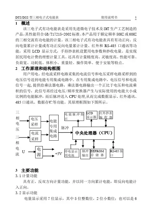
数显交流电压表芯片使用手册 采用STM8S003
- 格式:pdf
- 大小:753.95 KB
- 文档页数:7
2003BDIGITAL PANEL VOLTMETEROperator’sManual /manuals®NEWPORT Electronics,Inc.CountersFrequency MetersPID ControllersClock/TimersPrintersProcess MetersOn/Off ControllersRecordersRelative HumidityTransmittersThermocouplesThermistorsWire Rate Meters Timers Totalizers Strain Gauge Meters Voltmeters Multimeters Soldering Iron Testers pH pens pH Controllers pH Electrodes RTDs Thermowells Flow Sensors NEWPORT Electronics, Inc.®For Immediate Assistance In the U.S.A. and Canada: 1-800-NEWPORT®In Mexico: (95) 800-NEWPORTSMOr call your local NEWPORTOffice.Additional products fromIt is the policy of NEWPORT to comply with all worldwide safety and EMC/EMI regulations that apply.NEWPORT is constantly pursuing certification of its products to the European New Approach Directives. NEWPORT will add the CE mark to every appropriate device upon certification.The information contained in this document is believed to be correct but NEWPORT Electronics, Inc.accepts no liability for any errors it contains, and reserves the right to alter specifications without notice.WARNING: These products are not designed for use in, and should not be used for, patient connected applications.This device is marked with the international caution symbol. It is important to read the SetupGuide before installing or commissioning this device as it contains important information relating to safety and EMC.T A B L E O F C O N T E N T SSAFETY CONSIDERATION (ii)1.0DESCRIPTION . . . . . . . . . . . . . . . . . . . . . . . . . . . . . . . . . . . . . . . . . . . . . . . . . . . . . . .11.1GENERAL . . . . . . . . . . . . . . . . . . . . . . . . . . . . . . . . . . . . . . . . . . . . . . . . . . . . .11.2SPECIFICATIONS . . . . . . . . . . . . . . . . . . . . . . . . . . . . . . . . . . . . . . . . . . . . . . .22.0RECEIVING AND INSTALLATION . . . . . . . . . . . . . . . . . . . . . . . . . . . . . . . . . . . . . . . .62.1UNPACKING AND INSPECTION . . . . . . . . . . . . . . . . . . . . . . . . . . . . . . . . . . . .62.2INITIAL CHECKOUT PROCEDURE . . . . . . . . . . . . . . . . . . . . . . . . . . . . . . . . . .62.3MECHANICAL INSTALLATION . . . . . . . . . . . . . . . . . . . . . . . . . . . . . . . . . . . . . .73.0OPERATING INSTRUCTIONS . . . . . . . . . . . . . . . . . . . . . . . . . . . . . . . . . . . . . . . . . . .83.1PIN ASSIGNMENTS . . . . . . . . . . . . . . . . . . . . . . . . . . . . . . . . . . . . . . . . . . . . .83.2POWER . . . . . . . . . . . . . . . . . . . . . . . . . . . . . . . . . . . . . . . . . . . . . . . . . . . . . . .93.3SIGNAL INPUT . . . . . . . . . . . . . . . . . . . . . . . . . . . . . . . . . . . . . . . . . . . . . . . . .113.4RATIO . . . . . . . . . . . . . . . . . . . . . . . . . . . . . . . . . . . . . . . . . . . . . . . . . . . . . . .143.5DIGITAL SIGNALS . . . . . . . . . . . . . . . . . . . . . . . . . . . . . . . . . . . . . . . . . . . . . .143.6DECIMAL POINTS . . . . . . . . . . . . . . . . . . . . . . . . . . . . . . . . . . . . . . . . . . . . . .154.0 THEORY OF OPERATION . . . . . . . . . . . . . . . . . . . . . . . . . . . . . . . . . . . . . . . . . . . . .16FIGURE 4SIMPLIFIED BLOCK DIAGRAM OF UNIT. . . . . . . . . . . . . . . . . . . . . . . .17FIGURE 5CONVERSION CYCLE WAVE FORM . . . . . . . . . . . . . . . . . . . . . . . . . .185.0ADJUSTMENT AND CALIBRATION . . . . . . . . . . . . . . . . . . . . . . . . . . . . . . . . . . . . . .19 DRAWINGS . . . . . . . . . . . . . . . . . . . . . . . . . . . . . . . . . . . . . . . . . . . . . . . . . . . . . . . . . . . .20SAFETY CONSIDERATIONSUnpacking &InspectionUnpack the instrument and inspect for obvious shipping damage. Do not attempt to operate the unit if damage is found.This instrument is a panel mount device protected in accordance with Class I of EN 61010(115/230 AC power connections). Installation of this instrument should be done by Qualified personnel. In order to ensure safe operation, the following instructions should be followed.This instrument has no power-on switch. An external switch or circuit-breaker shall be included in the building installation as a disconnecting device. It shall be marked to indicate this function, and it shall be in close proximity to the equipment within easy reach of the operator. The switch or circuit-breaker shall not interrupt the Protective Conductor (Earth wire), and it shall meet the relevant requirements of IEC 947–1 and IEC 947-3 (International Electrotechnical Commission). The switch shall not be incorporated in the mains supply cord.Furthermore, to provide protection against excessive energy being drawn from the mains supply in case of a fault in the equipment, an overcurrent protection device shall be installed.•The Protective Conductor must be connected for safety reasons. Check that the power cable has the proper Earth wire, and it is properly connected. It is not safe to operate this unit without the Protective Conductor Terminal connected.•Do not exceed voltage rating on the label located on the top of the instrument housing.•Always disconnect power before changing signal and power connections.•Do not use this instrument on a work bench without its case for safety reasons.•Do not operate this instrument in flammable or explosive atmospheres.•Do not expose this instrument to rain or moisture.EMC Considerations•Whenever EMC is an issue, always use shielded cables.•Never run signal and power wires in the same conduit.•Use signal wire connections with twisted-pair cables.•Install Ferrite Bead(s) on signal wires close to the instrument if EMC problems persist.This device is marked with the international Caution symbol. It is important to read this manual before installing or commissioning this device as it contains important information relating to Safety and EMC(Electromagnetic Compatibility).PCBA DWG, 2003B, 4 1/2 DIGIT DPVMPCBA DWG, 2003B, 4 1/2 DIGIT DPVM - SOLDERSWITCHESOUTLINE AND MOUNTING FOR DIN 1A CASEOUTLINE AND MOUNTING FOR OPTIONAL NEMA CASE D W G N O .05169 BFor immediate technical or application assistance please call:Newport Electronics, Inc.2229 South Yale Street • Santa Ana, CA • 92704 • U.S.A.TEL: (714) 540-4914 • FAX: (203) 968-7311TollFree:1-800-639-7678••e-mail:******************ISO 9001 CertifiedNewport Technologies, Inc.976 Bergar • Laval (Quebec) • H7L 5A1 • CanadaTEL: (514) 335-3183 • FAX: (514) 856-6886TollFree:1-800-639-7678•www.newport.ca•e-mail:***************Newport Electronics, Ltd.One Omega Drive • River Bend Technology CentreNorthbank, Irlam • Manchester M44 5BD • United KingdomTel: +44 161 777 6611 • FAX: +44 161 777 6622TollFree:0800488488••e-mail:******************.ukNewport Electronics B.V.Postbus 8034 • 1180 LA Amstelveen • The NetherlandsTEL: +31 20 3472121 • FAX: +31 20 6434643TollFree:08000993344•www.newport.nl•e-mail:***************Newport Electronics spol s.r.o.Frystatska 184, 733 01 Karviná • Czech RepublicTEL: +420 59 6311899 • FAX: +420 59 6311114TollFree:0800-1-66342•www.newport.cz•e-mail:***************Newport Electronics GmbHDaimlerstrasse 26 • D-75392 Deckenpfronn • GermanyTEL: 49 7056 9398-0 • FAX: 49 7056 9398-29TollFree:0800/6397678•www.newport.de•e-mail:****************Newport Electronique S.A.R.L.11, rue Jacques Cartier • 78280 Guyancourt • FranceTEL: +33 1 61 37 29 00 • FAX: +33 1 30 57 54 27TollFree:0800466342•www.newport.fr•e-mail:****************Mexico and Latin AmericaFAX: 001 (203) 359-7807En Español: 001 (203) 359-7803。

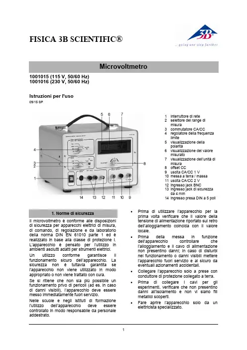
FISICA 3B SCIENTIFIC®11001015 (115 V, 50/60 Hz) 1001016 (230 V, 50/60 Hz)Istruzioni per l'uso09/15 SP1 interruttore di rete2 selettore del range dimisura3 commutatore CA/CC4 regolatore della frequenzalimite5 visualizzazione dellapolarità6 visualizzazione del valoremisurato7 visualizzazione dell’unità dimisura 8 offset CC9 uscita CA/CC 1 V10 messa a terra / massa 11 uscita CA/CC 2 V 12 ingresso jack BNC13 ingresso jack di sicurezzada 4 mm14 ingresso presa DIN a 5 poliIl microvoltmetro è conforme alle disposizioni di sicurezza per apparecchi elettrici di misura, di comando, di regolazione e da laboratorio della norma DIN EN 61010 parte 1 ed è realizzato in base alla classe di protezione I. L’apparecchio è pensato per l’utilizzo in ambienti asciutti adatti per strumenti elettrici. Un utilizzo conforme garantisce il funzionamento sicuro dell’apparecchio. La sicurezza non è tuttavia garantita se l’apparecchio non viene utilizzato in modo appropriato o non viene trattato con cura.Se si ritiene che non sia più possibile un funzionamento privo di pericoli (ad es. in caso di danni visibili), l’apparecchio deve essere messo immediatamente fuori servizio.Nelle scuole e negli istituti di formazione l’utilizzo dell’apparec chio deve essere controllato in modo responsabile da personale addestrato.∙Prima di utilizzare l’apparecchio per la prima volta verificare che il valore della tensione di alimentazione riportato sul retro dell’alloggiamento coincida con il valore locale.∙Prima della messa in funzione dell’apparecchio controllare che l’alloggiamento e il cavo di alimentazione non presentino danni; in caso di disturbi nel funzionamento o danni visibili mettere l’apparecchio fuori servizio e al sicuro da eventuali azionamenti accidentali.∙ Collegare l'apparecchio solo a prese con conduttore di protezione collegato a terra. ∙Prima di collegare i cavi per gli esperimenti, verificare che non presentino danni all’isolamento e non vi siano fili metallici scoperti.∙Fare aprire l’appa recchio solo da un elettricista specializzato.3B Scientific GmbH ▪ Rudorffweg 8 ▪ 21031 Hamburgo ▪ Germania ▪ Con riserva di modifiche tecniche © Copyright 2015 3B Scientific GmbHL'apparecchio consente di misurare e amplificare tensioni continue e alternate estremamente piccole (max. 2 V), come ad es. tensioni a induzione, termiche e ottiche. La misurazione viene indicata su un display a LED. Inoltre è possibile collegare anche un misuratore dimostrativo. Il segnale di misura viene alimentato mediante un jack BNC o un jack di sicurezza da 4 mm. Un commutatore consente di eseguire misurazioni in CA o CC. Nell'ingresso di misura è possibile collegare un filtro per il livellamento del segnale o per la limitazione superiore della frequenza di misura. Si possono impostare 4 frequenze fisse. Il filtro consente di ridurre le tensioni di disturbo durante le misurazioni di tensioni continue e alternate. Una presa DIN supplementare permette di collegare facilmente delle sonde di Hall.L’apparecchio 1001015 è progettato per una tensione di rete di 115 V (±10 %), 1001016 per 230 V (±10 %).Tensione di uscita: 0 – ±2 V Corrente di uscita:max. 1 mAResistenza d'entrata: range CC: 100 k Ω range CA: 900 k ΩVisualizzazione misura: display LED a 3,5 cifre Collegamenti in ingresso: 2 jack di sicurezzada 4 mm ,jack BNC presa DIN a 5 poliCollegamenti in uscita: 3 jack di sicurezza da4 mmTensione di alimentazione: vedere sul retrodell’alloggiamentoFusibile primario: vedere sul retrodell’alloggiamentoDimensioni: 235 × 250 × 180 mm³ Peso: ca. 3,3 kg4.1 Funzionamento come misuratore CC ∙ Applicare la tensione di esercizio. ∙ Impostare il commutatore su CC.∙Impostare il range di misura (200 μV –200 mV).∙ Mettere in cortocircuito l’ingresso e regolare il punto zero con l’offset CC.∙ Rimuovere il cortocircuito e collegare ilcarico all’ingresso.4.2 Funzionamento come misuratore CA ∙ Applicare la tensione di esercizio. ∙ Impostare il commutatore su CA.∙ Impostare il range di misura (200 μV –200 mV).∙Collegare il carico all’ingresso.4.3 Funzionamento come amplificatore dimisura CC∙ Applicare la tensione di esercizio. ∙ Impostare il commutatore su CC.∙ Impostare il range di misura (200 μV –200 mV).∙ Mettere i n cortocircuito l’ingresso e regolare il punto zero con l’offset CC.∙Rimuovere il cortocircuito e collegare il misuratore dimostrativo (visualizzazione analogica, range di misura fino a 2 V) all’uscita.∙Collegare il carico all’ingresso.4.4 Funzionamento come amplificatore dimisura CA∙ Applicare la tensione di esercizio. ∙ Impostare il commutatore su CA.∙ Impostare il range di misura (200 μV –200 mV).∙Collegare il misuratore dimostrativo (visualizzazione analogica, range di misura fino a 2 V) all’uscita.∙Collegare il carico all’ingresso.∙ Smaltire l'imballo presso i centri di raccolta e riciclaggio locali. ∙Non gettare l'apparecchio nei rifiuti domestici. Perlo smaltimento delle appare- cchiature elettriche, rispet- tare le disposizioni vigenti a livello locale.∙Non gettare le batterie esaurite nei rifiuti domestici. Rispettare le disposizioni legali locali (D: BattG; EU: 2006/66/EG).。
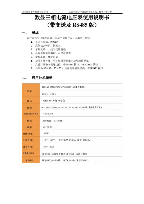
数显三相电流电压表使用说明书(带变送及RS485版)一、概述该产品是采用单片机设计而成的最新产品,具有以下特点:1、正四位显示,0-99992、高位AD转换,精度高。
3、单片机设计,抗干扰性能强4、具有多项菜单编程,可灵活操作5、量程准确,性能可靠6、功能扩展方便,可扩展报警输出口及可编程单元。
7、具备三路独立变送功能,带RS485接口,MODBUS协议8、外形为80×80,72×72不具备变送输出功能,带RS485接口二、通用技术指标三、接线图四、编程说明五、变送输出该产品具备变送输出及RS485输出。
具体操作如下:变送输出:1、首先确定仪表变送输出量程,一般可选0-20mA或4-20mA,如果需要电压信号,只需在电流输出两端并上精密电阻,输出电压精度由电阻决定。
2、第一路电流/电压对应第一路变送输出,其它二路与之类似。
3、变送输出最大值由信号量程决定,如AC5A量程,则输入电流信号为5A时对应输出20mA六、数字通讯MODBUS协议只允许在主机(PC,PLC等)和终端设备之间通讯,而不允许独立的终端设备之间的数据交换,这样各终端设备不会在它们初始化时占据通讯线路,而仅限于响应到达本机的查询信号。
主机查询:查询消息帧包括设备地址码、功能人码、数据信息码、校验码。
地址码表明要选中的从机设备;功能代码告之被选中的从设备要执行何种功能,例如功能代码03或04是要求从设备读寄存器并返回它们的内容;数据段包含了从设备要执行功能的其它附加信息,如在读命令中,数据段的附加信息有从何寄存器开始读的寄存器数量;校验码用来检验一帧信息的正确性,为从设备提供了一种验证消息内容是否正确的方法,它采用CRC16的校准规则。
从机响应:如果从设备产生一正常的回应,在回应消息中有从机地址码、功能代码、数据信息码和CRC16校验码。
数据信息码包括了从设备收集的数据:如寄存器值或状态。
如果有错误发生,我们约定是从机不进行响应。


• 166•由于人类生产生活的影响,地球大气臭氧层受到了严重破坏,紫外线到达地面的强度增大。
为了预防过度的紫外线照射对人体造成的危害,人们有必要较准确地了解实时的紫外线强度,以便及时地采取相应的预防措施。
而市场上紫外线强度检测仪表普遍价格昂贵,且体积较大,不适合于人们日常的使用。
本文设计了一种基于stm8s 单片机的实时便携式紫外线监测器,采用进口UVM-30高精度紫外线感光器对紫外线光源进行强度检测,经过转换调理电路,将实时的紫外线强度转化为具有友好界面的效果的LCD 显示屏显示出来。
具有高精度,小型化,低功耗等特点。
1 总体设计方案在本系统的电路设计方框图如图1所示,整个系统设计有7个组成部分:①控制部分主芯片采用单片机STM8S003F3;②显示部分采用FTP1018显示屏;③采集部分采用UVM-30紫外线传感器;④按键控制;⑤SGM8521放大器;⑥电压转换模块;⑦电源模块。
图1 电路设计方框图2 硬件设计2.1 STM8的引脚电路STM8S003F3成本低,体积小,容量与引脚可以满足本设计的要求,所以微控制器选择STM8S003F3单片机的贴片封装形式。
其共有引脚20个,设计中只用到了18个引脚,其它引脚均没有外接,本设计的单片机的电路如图2所示。
图2 单片机的引脚电路图2.2 电源模块电路本次设计使用PT1301 DC/DC 升压转换器,其最小启动电压低于1V 。
随着使用时间的增加,系统电池电压会减小,影响工作,通过本升压电路,即可满足整个系统对电源的的需求,减小电源成本,延长系统使用寿命。
PT1301内置2A 电源开关,锂电池供电时可提供高达300mA 的输出电流。
输出电压由外部电阻R11与R12决定,最小静态电流为14μA ,功耗很低。
500KHz 是固定的开关频率,效率可达90%,处在关断状态下工作电流为0。
图3所示为电源模块电路图。
图3 电源模块电路图2.3 紫外线感光电路UVM-30紫外线感光器设计小巧,紫外线感光器反应十分灵敏,采用线性电压信号输出,是专门为方便人们高精确测量紫外线指数而设计的,精确可靠。

UM0560User manualSTM8 bootloader 1 IntroductionThis document describes the features and operation of the STM8 integrated bootloaderprogram. This code embedded in the system memory of the device (ROM memory allowsmemories, including Flash program, data EEPROM, and RAM, to be written into the deviceusing the standard serial interfaces LINUART/UART/USART, SPI, and CAN.The bootloader code is similar for all STM8 versions. However, even though a peripheralmay be present in a product, the product may not support it (for example the SPI is notsupported in 128 Kbyte devices. In addition, different STM8 device types support differentperipherals (see Table5: Serial interfaces associated with STM8 devices for detailedinformation.For further information on the STM8 family features, pinout, electrical characteristics,mechanical data and ordering information, please refer to the STM8 datasheets.March 2011Doc ID 14798 Rev 41/70Contents UM0560Contents1Introduction . . . . . . . . . . . . . . . . . . . . . . . . . . . . . . . . . . . . . . . . . . . . . . . . 12Bootloader introduction . . . . . . . . . . . . . . . . . . . . . . . . . . . . . . . . . . . . . . 62.1Bootloader activation . . . . . . . . . . . . . . . . . . . . . . . . . . . . . . . . . . . . . . . . . 73Peripheral settings . . . . . . . . . . . . . . . . . . . . . . . . . . . . . . . . . . . . . . . . . 113.1USART/UARTs settings . . . . . . . . . . . . . . . . . . . . . . . . . . . . . . . . . . . . . . 11 3.1.1LINUART/UARTs in “reply” mode settings . . . . . . . . . . . . . . . . . . . . . . . 11 3.2SPI settings . . . . . . . . . . . . . . . . . . . . . . . . . . . . . . . . . . . . . . . . . . . . . . . 123.3CAN settings . . . . . . . . . . . . . . . . . . . . . . . . . . . . . . . . . . . . . . . . . . . . . . 134Bootloader command set . . . . . . . . . . . . . . . . . . . . . . . . . . . . . . . . . . . . 144.1Get command . . . . . . . . . . . . . . . . . . . . . . . . . . . . . . . . . . . . . . . . . . . . . . 154.1.1Get command via USART/LINUART/UART1/ UART2/UART3 . . . . . . . . 15 4.1.2Get command via SPI . . . . . . . . . . . . . . . . . . . . . . . . . . . . . . . . . . . . . . 174.1.3Get command via CAN . . . . . . . . . . . . . . . . . . . . . . . . . . . . . . . . . . . . . 194.2Read memory command . . . . . . . . . . . . . . . . . . . . . . . . . . . . . . . . . . . . . 214.2.1Read memory command via USART/LINUART/UART1/UART2/UART3 214.2.2Read memory command via SPI . . . . . . . . . . . . . . . . . . . . . . . . . . . . . . 234.2.3Read memory command via CAN . . . . . . . . . . . . . . . . . . . . . . . . . . . . . 264.3Erase memory command . . . . . . . . . . . . . . . . . . . . . . . . . . . . . . . . . . . . . 274.3.1Erase memory command via USART/LINUART/UART1/UART2/UART3 . . . . . . . . . . . . . . . . . . . . . . . . . . . . . . . . . . . . . . . . . . . . . . . . . . 284.3.2Erase memory command via SPI . . . . . . . . . . . . . . . . . . . . . . . . . . . . . 314.3.3Erase memory command via CAN . . . . . . . . . . . . . . . . . . . . . . . . . . . . 334.4Write memory command . . . . . . . . . . . . . . . . . . . . . . . . . . . . . . . . . . . . . 354.4.1Write memory command via USART/LINUART/UART1/UART2/UART3 364.4.2Write memory command via SPI . . . . . . . . . . . . . . . . . . . . . . . . . . . . . . 384.4.3Write memory command via CAN . . . . . . . . . . . . . . . . . . . . . . . . . . . . . 414.5Speed command . . . . . . . . . . . . . . . . . . . . . . . . . . . . . . . . . . . . . . . . . . . 434.5.1Speed command via CAN . . . . . . . . . . . . . . . . . . . . . . . . . . . . . . . . . . . 434.6Go command . . . . . . . . . . . . . . . . . . . . . . . . . . . . . . . . . . . . . . . . . . . . . . 454.6.1Go command via USART/LINUART/UART1/UART2/UART3 . . . . . . . . . 454.6.2Go command via SPI . . . . . . . . . . . . . . . . . . . . . . . . . . . . . . . . . . . . . . . 472/70Doc ID 14798 Rev 4UM0560Contents4.6.3Go command via CAN . . . . . . . . . . . . . . . . . . . . . . . . . . . . . . . . . . . . . . 494.7Sector codes . . . . . . . . . . . . . . . . . . . . . . . . . . . . . . . . . . . . . . . . . . . . . . 504.8Software model (STM8A/L/S . . . . . . . . . . . . . . . . . . . . . . . . . . . . . . . . . . 564.8.1RAM erase/write routines . . . . . . . . . . . . . . . . . . . . . . . . . . . . . . . . . . . 575Error management . . . . . . . . . . . . . . . . . . . . . . . . . . . . . . . . . . . . . . . . . 586Programming time . . . . . . . . . . . . . . . . . . . . . . . . . . . . . . . . . . . . . . . . . . 59Appendix A How to upload ROP protected device . . . . . . . . . . . . . . . . . . . . . . . 60A.1Rules for upgrading ROP protected devices. . . . . . . . . . . . . . . . . . . . . . . 60 Appendix B Bootloader entry points . . . . . . . . . . . . . . . . . . . . . . . . . . . . . . . . . . 61Appendix C SPI peripheral timing options. . . . . . . . . . . . . . . . . . . . . . . . . . . . . . 62C.1SPI with busy state checking. . . . . . . . . . . . . . . . . . . . . . . . . . . . . . . . . . . 62C.2Modified erase/write RAM routines. . . . . . . . . . . . . . . . . . . . . . . . . . . . . . 62 Appendix D PC software support . . . . . . . . . . . . . . . . . . . . . . . . . . . . . . . . . . . . . 63Appendix E Bootloader UART limitation . . . . . . . . . . . . . . . . . . . . . . . . . . . . . . . 64E.1Description . . . . . . . . . . . . . . . . . . . . . . . . . . . . . . . . . . . . . . . . . . . . . . . . 64E.1.1UART automatic baudrate calculation. . . . . . . . . . . . . . . . . . . . . . . . . . . 64E.1.2Description of UART limitation . . . . . . . . . . . . . . . . . . . . . . . . . . . . . . . . 64E.2Workaround for UART limitation . . . . . . . . . . . . . . . . . . . . . . . . . . . . . . . . 65 Appendix F Limitations and improvements versus bootloader versions. . . . . 66 Revision history . . . . . . . . . . . . . . . . . . . . . . . . . . . . . . . . . . . . . . . . . . . . . . . . . . . . 68Doc ID 14798 Rev 43/70List of tables UM0560 List of tablesTable 1.STM8 subfamilies featuring abootloader. . . . . . . . . . . . . . . . . . . . . . . . . . . . . . . . . . . . . . . 6 Table 2. STM8 subfamilies without bootloader . . . . . . . . . . . . . . . . . . . . . . . . . . . . . . . . . . . . . . . . . 7 Table3.Bootloader versions for which bootloader activation flowchart isvalid. . . . . . . . . . . . . . . . . 7 Table 4.Initialchecking . . . . . . . . . . . . . . . . . . . . . . . . . . . . . . . . . . . . . . . . . . . . . . . . . . . . . . . . . . 10 Table 5.Serial interfaces associated with STM8devices. . . . . . . . . . . . . . . . . . . . . . . . . . . . . . . . . 11 Table 6.Bootloadercommands . . . . . . . . . . . . . . . . . . . . . . . . . . . . . . . . . . . . . . . . . . . . . . . . . . . . 14 Table 7.Bootloader codes . . . . . . . . . . . . . . . . . . . . . . . . . . . . . . . . . . . . . . . . . . . . . . . . . . . . . . . .14 Table 8.Examples ofdelay . . . . . . . . . . . . . . . . . . . . . . . . . . . . . . . . . . . . . . . . . . . . . . . . . . . . . . . 39 Table9.STM8 sector codes. . . . . . . . . . . . . . . . . . . . . . . . . . . . . . . . . . . . . . . . . . . . . . . . . . . . . . .50 Table 10.Errortable. . . . . . . . . . . . . . . . . . . . . . . . . . . . . . . . . . . . . . . . . . . . . . . . . . . . . . . . . . . . . . 58 Table ART/LINUART/UART1/UART2/UART3 programmingtimes. . . . . . . . . . . . . . . . . . . . . 59 Table 12.SPI programmingtime . . . . . . . . . . . . . . . . . . . . . . . . . . . . . . . . . . . . . . . . . . . . . . . . . . . . 59 Table 13.CAN programming time . . . . . . . . . . . . . . . . . . . . . . . . . . . . . . . . . . . . . . . . . . . . . . . . . . . 59 Table 14.Bootloader entrypoints. . . . . . . . . . . . . . . . . . . . . . . . . . . . . . . . . . . . . . . . . . . . . . . . . . . . 61 Table15.Description of limitation, improvements and addedfeatures . . . . . . . . . . . . . . . . . . . . . . . 66 Table 16.Document revisionhistory . . . . . . . . . . . . . . . . . . . . . . . . . . . . . . . . . . . . . . . . . . . . . . . . . 68 4/70Doc ID 14798 Rev 4UM0560List of figures List of figuresFigure 1.Bootloader activation flowchart . . . . . . . . . . . . . . . . . . . . . . . . . . . . . . . . . . . . . . . . . . . . . . 8 Figure 2.CANframe . . . . . . . . . . . . . . . . . . . . . . . . . . . . . . . . . . . . . . . . . . . . . . . . . . . . . . . . . . . . . 13 Figure 3.Get command via USART/LINUART/UART1/UART2/UART3 - hostside . . . . . . . . . . . . . 15 Figure 4.Get command viaUSART/LINUART/UART1/UART2/UART3 - device side. . . . . . . . . . . . 16 Figure5.Get command via SPI - host side. . . . . . . . . . . . . . . . . . . . . . . . . . . . . . . . . . . . . . . . . . . .17 Figure 6.Get command via SPI - deviceside . . . . . . . . . . . . . . . . . . . . . . . . . . . . . . . . . . . . . . . . . . 18 Figure 7.Get command via CAN - host side. . . . . . . . . . . . . . . . . . . . . . . . . . . . . . . . . . . . . . . . . . . 19 Figure 8.Get command via CAN - device side . . . . . . . . . . . . . . . . . . . . . . . . . . . . . . . . . . . . . . . . . 20 Figure 9.Read memory command via USART/LINUART/UART1/UART2/UART3 - host side. . . . . 21 Figure 10.Read memory command viaUSART/LINUART/UART1/UART2/UART3 - device side . . . 22 Figure 11.Read memory command via SPI - host side . . . . . . . . . . . . . . . . . . . . . . . . . . . . . . . . . . . 23 Figure 12.Read memory command via SPI - deviceside. . . . . . . . . . . . . . . . . . . . . . . . . . . . . . . . . . 25 Figure 13.Read memory command via CAN - host side. . . . . . . . . . . . . . . . . . . . . . . . . . . . . . . . . . . 26 Figure 14.Read memory command via CAN - device side. . . . . . . . . . . . . . . . . . . . . . . . . . . . . . . . . 26 Figure 15.Erase memory command via USART/LINUART/UART1/UART2/UART3 - host side. . . . . 28 Figure 16.Erase memory command viaUSART/LINUART/UART1/UART2/UART3 - device side. . . 30 Figure 17.Erase memory command via SPI - host side . . . . . . . . . . . . . . . . . . . . . . . . . . . . . . . . . . . 31 Figure 18.Erase memory command via SPI - deviceside . . . . . . . . . . . . . . . . . . . . . . . . . . . . . . . . . 32 Figure 19.Erase memory command via CAN - host side . . . . . . . . . . . . . . . . . . . . . . . . . . . . . . . . . . 33 Figure 20.Erase memory command via CAN - device side . . . . . . . . . . . . . . . . . . . . . . . . . . . . . . . . 34 Figure 21.Write memory command via USART/LINUART/UART1/UART2/UART3 - hostside . . . . . 36 Figure 22.Write memory command viaUSART/LINUART/UART1/UART2/UART3 - device side . . . 37 Figure 23.Write memory command via SPI - host side. . . . . . . . . . . . . . . . . . . . . . . . . . . . . . . . . . . . 38 Figure 24.Write memory command via SPI - deviceside. . . . . . . . . . . . . . . . . . . . . . . . . . . . . . . . . . 40 Figure 25.Write memory command via CAN - host side. . . . . . . . . . . . . . . . . . . . . . . . . . . . . . . . . . . 41 Figure 26.Write memory command via CAN - device side. . . . . . . . . . . . . . . . . . . . . . . . . . . . . . . . . 42 Figure 27.Speed command via CAN - hostside. . . . . . . . . . . . . . . . . . . . . . . . . . . . . . . . . . . . . . . . . 43 Figure 28.Speed command via CAN - device side. . . . . . . . . . . . . . . . . . . . . . . . . . . . . . . . . . . . . . . 44 Figure 29.Go command via USART/LINUART/UART1/UART2/UART3 - host side. . . . . . . . . . . . . .45 Figure 30.Go command via USART/LINUART/UART1/UART2/UART3 - device side . . . . . . . . . . . . 46 Figure 31.Go command via SPI - hostside . . . . . . . . . . . . . . . . . . . . . . . . . . . . . . . . . . . . . . . . . . . . 47 Figure 32.Go command via SPI - device side. . . . . . . . . . . . . . . . . . . . . . . . . . . . . . . . . . . . . . . . . . . 48 Figure 33.Go command via CAN - hostside . . . . . . . . . . . . . . . . . . . . . . . . . . . . . . . . . . . . . . . . . . . 49 Figure 34.Go command via CAN - device side. . . . . . . . . . . . . . . . . . . . . . . . . . . . . . . . . . . . . . . . . . 49 Figure35.Delay elimination in modified RAMroutines . . . . . . . . . . . . . . . . . . . . . . . . . . . . . . . . . . . 62 Figure 36."Flash loader demonstrator" software. . . . . . . . . . . . . . . . . . . . . . . . . . . . . . . . . . . . . . . . . 63Doc ID 14798 Rev 45/706/70Doc ID 14798 Rev 42 Bootloader introductionThe main task of the bootloader is to download the application program into the internalmemories through the integrated peripherals (UARTs, SPI, or CAN without using the SWIM protocol and dedicated hardware. Data are provided by any device (host which is capable of sending information through one of the above-mentioned serial interfaces.The bootloader permits downloading of application software into the device memories, including RAM, program and data memory, using standard serial interfaces. It is a complementary solution to programming via the SWIM debugging interface.The bootloader code is stored in the internal boot ROM memory. After a reset, thebootloader code checks whether the program memory is virgin or whether a specific option byte is set allowing code modifications.If these conditions are not fulfilled, the bootloader resumes and the user application is started.In case of a successful check the bootloader is executed.When the bootloader procedure starts, the main tasks are:●Polling all supported serial interfaces to check which peripheral is used●Programming code, data, option bytes and/or vector tables at the address(es received from the host.Each STM8 device embeds a specific bootloader code which is common to a whole group of STM8 devices. The correspondence between STM8 groups and STM8 part numbers is given in Table 1. Group names are used all over this user manual.Table 2 gives the list of STM8 devices without embedded bootloader (no ROM bootloader is implemented inside the microcontroller. When using these devices, youhave to write your own bootloader code and save it in the UBC program area (refer to STM8S and STM8A families reference manual for information on the UBC area.Table 1.STM8 subfamilies featuring a bootloaderSTM8 group STM8 part numbersSTM8A/S-128KSTM8AF52xx, STM8AF6269/8x/Ax, STM8AF51xx, STM8AF6169/7x/8x/9x/Ax,STM8S20xxx STM8A/S-32KSTM8AF622x/4x, STM8AF6266/68, STM8AF612x/4x, STM8AF6166/68,STM8S105xxSTM8L-64k STM8L15xx8, STM8L15xR6, STM8L16xx8STM8L-32KSTM8L15xC4, STM8L15xK4, STM8L15xG4,STM8L15xC6, STM8L15xK6, STM8L15xG6(x = 1 or 2STM8L-8KSTM8L15xC2, STM8L15xK2, STM8L15xG2, STM8L15xC3, STM8L15xK3, STM8L15xG3(x = 1 or 2Doc ID 14798 Rev 47/702.1 Bootloader activationThe STM8 hardware reset vector is located at the beginning of the boot ROM(0x006000,while the other interrupt vectors are in the Flash program memory starting at address 0x008004.The device executes the boot ROM (jumps inside the boot ROM area and after checking certain address locations (see Table 4: Initial checking on page 10, it starts to execute the bootloader or the user code defined by the reset vector (0x008000.The bootloader activation flowchart is described in Figure 1: Bootloader activation flowchart . In previous bootloader versions, a return to the “wait for SYNCHR” state (see dashed line in Figure 1 was performed when the “Flash virgin” test was positive. In newer versions, it has been replaced by a software (SW reset to prevent the customer firmware from remaining in a infinite loop (e.g. due to EMC disturbance. This bootloader modification is referred to as "EMC lockup protection" in T able 15. Table 3 lists the bootloader versions for which the dashed line was replaced by a SW reset.The bootloader version number of a given device is obtained by the “Get command” (see Section 4.1: Get command . The bootloader version is represented by a two-digitbinary-coded decimal (BCD number (with a decimal point between the two digits which is coded into one byte in the “Get command” result. For example, 0x21 version byte is bootloader version 2.1.Table 2.STM8 subfamilies without bootloaderSTM8 group STM8 part numbersSTM8A/S-8K STM8Sx03xx STM8L-8KSTM8L101xxTable 3.Bootloader versions for which bootloader activation flowchart is validSTM8 group Bootloader versionSTM8A/S-128K v2.2STM8A/S-32K v1.3STM8L-64K v1.0STM8L-32K v1.2STM8L-8Kv1.01.See Flow chart description on page9 for explanation of points 1 to 8.2.See Table4: Initial checking.3.Dotted routines are loaded in RAM by the host. They are removed by the go command before jumping to the Flash programmemory to execute an application.8/70Doc ID 14798 Rev 4Flow chart description1.Disable all interrupt sources.2. The host can start the bootloader process according to checks shown in Table4 (inkeeping with the content of the first Flash program memory location (0x008000 and “bootloader enable” option bytes. The host checks the following bootloader startconditions:Condition 1: the host checks if the device memory is empty by inspecting the content of address 0x00 8000 (reset vector. If the content is not equal to 0x82 or 0xAC, thedevice is recognized as being empty and the bootloader remains active and waits for host commands without timeouts.Condition 2: the host checks if the bootloader option bytes (two bytes are set to enable the bootloader or not. The bootloader is enabled with a value of 0x55AA and disabled by all other values (see the device datasheets for the bootloader option byte locations.If the option bytes are enabled, the bootloader remains active and waits for hostcommands with a 1-second timeout. If the host does not send a command within this timeout, the bootloader jumps directly to the application user vector (jump to address0x008000.Condition 3: If the option bytes disable the bootloader (by a value different from0x55AA, the bootloader jumps directly to the application user vector (jump to address 0x00 8000.The above checking process is summarized in T able4.3. When readout protection (ROP is active, the Flash program memory is readoutprotected. In this case, the bootloader stops and the user application starts. If ROP is inactive, the bootloader continues to be executed (see Appendix A: How to upload ROP protected device.4. The CAN peripheral can only be used if an external clock (8 MHz, 16 MHz, or 24 MHzis present. It is initialized at 125 kbps. The UARTs and SPI peripherals do not require an external clock.5. Set the high speed internal RC oscillator (HSI to 16 MHz and initialize the UARTsreceiver pins in input pull-up mode in the GPIO registers. Initialize the SPI in slave mode. Then, wait 4 ms for I/O pin voltage level stabilization. It is recommended that the host waits 10 ms from the STM8 reset before sending the SYNCHR byte/message.This is the time needed for bootloader initialization.Doc ID 14798 Rev 49/7010/70Doc ID 14798 Rev 46.Interface polling: The bootloader polls all peripherals waiting for a synchronizationbyte/message (SYNCHR = 0x7F within a timeout of 1 s. If a timeout occurs, either the Flash program memory is virgin in which case it waits for a synchronizationbyte/message in an infinite loop through a software reset, or the Flash programmemory is not virgin and the bootloader re stores the registers’ reset status and jumps to the memory address given by the reset vector (located at 0x008000. For thebootloader versions listed in Table 3, a software reset is generated after a timeout has elapsed, in case the Flash program memory is empty (this is because it is safer to stay in an infinite loop if there is a hardware chip error.Note:When synchronization fails (the bootloader receives a byte/message different to‘SYNCHR’ = 0x7F two different situations can be distinguished according to the peripheral:With the UART peripherals, a device reset or power-down is necessary beforesynchronization can be tried again. Refer to Appendix E: Bootloader UART limitation With the CAN or SPI peripheral, the user can continue to poll the interfaces until a synchronization or a timeout occurs.7.If the synchronization message is received by the UARTs, the bootloader automatically detects the baud rate, initializes the UART and goes to step 8 below. If thesynchronization message is received by the CAN or SPI, the bootloader goes directly to step 8 below.Note: Once one of the available interfaces receives the synchronization message, all others are disabled.8.Waiting for commands: Commands are checked in an infinite loop and executed. To exit from the bootloader, the host has to send a ‘GO’ command. When this is done, the bootloader removes the EM and WM routines from the RAM memory and jumps to the address selected by the host.Note:To be able to write/erase data in Flash and EEPROM the host must write into RAMexecutable routines for writing and erasing. Those routines (*.s19 files are provided with the bootloader. Host must upload those routines at address 0xA0. See section 4.8.1: RAM erase/write routines for more information.Note:After interface initialization, the ROP bit is checked to avoid non-authorized reading of the Flash program memory and data EEPROM.Table 4.Initial checkingChecksProgram memory byte location [0x008000]Bootloader check option bytes[BL_OPT](11.See device datasheet for the [BL_OPT] location in the option byte area memory map.Actual Flash program memory status-> Flash action1st [0x00 8000] <>(0x82 or 0xAC[BL_OPT] = 0x00XXXX Flash program memory virgin.-> jump to bootloader 2nd[0x00 8000] <>(0x82 or 0xAC[BL_OPT] = 0x0055AA Flash program memory already written, bootloader enabled by option bytes.-> jump to bootloader 3rd[0x00 8000] <>(0x82 or 0xAC[BL_OPT] <> 0x0055AAFlash program memory already written,bootloader disabled by option bytes.-> jump to Flash program memory resetUM0560Peripheral settingsDoc ID 14798 Rev 411/703 Peripheral settingsThis section describes the hardware settings of the STM8 communication peripherals:●UARTs/LINUART ●SPI ●CANNote:During bootloading only one peripheral (first addressed is enabled. All others are disabled.3.1 USART/UARTs settingsThis peripheral supports asynchronous serial communication.The USART/UARTs settings are:●Data frame: 1 start bit, 8 data bit, 1 parity bit set to even, 1 stop bit●Baud rate: The baud rate is automatically detected by the bootloader. When the usersends the synchronization byte, 0x7F , the bootloader automatically detects the baud rate and sets the USART/UARTs to the same baud rate. Maximum baud rate = 1 Mbps (115200 baud for STM8L-64K; minimum baud rate = 4800 bps.To perform the automatic speed detection, the RxD line must be stable in the application board (internal pull-up is enabled on the RxD line by the bootloader.3.1.1 LINUART/UARTs in “reply” mode settingsSettings are:●Data frame: 1 start bit, 8 data bit, no parity bit, 1 stop bit●Baud rate: The baud rate is automatically detected by the bootloader. When the user sends the synchronization byte 0x7F , the bootloader automatically detects the baud rate and sets the UARTs to the same baud rate. Maximum baud rate = 550 kbps (115200 baud for STM8L-64K; minimum baud rate = 4800 bps.To perform automatic speed detection, the RxD line must be stable in the application board (internal pull-up is enabled on the RxD line by the bootloader.Table 5.Serial interfaces associated with STM8 devices (11.The above table reflects only current bootloader versions and device states.STM8 groups Serial interfaceSTM8A-128K USART , LINUART (in “reply” mode, CAN STM8A-32K LINUART, SPISTM8S-128K UART1, UAR T3 (in “reply” mode, CAN STM8S-32K UART2 (in “reply” mode, SPI STM8L-8K UART, SPI STM8L-32K UARTSTM8L-64KUART1, UART2, UART3 (in “reply” mode,SPI1, SPI2Peripheral settings UM056012/70Doc ID 14798 Rev 4Reply modeThe host must reply to all the bytes sent from the bootloader. If TxD and RxD lines share the same physical medium (for example, 1-wire communication, then host replies are not necessary since RxD and TxD pins coincide.3.2 SPI settingsThe SPI settings are:●8 data bit, MSB first●Bit rate: S et by the host which acts as a master●Peripheral set in slave mode with software management of NSS●Data polarity : CPOL = 0 (SCK to 0 when idle, CPHA = 0 (the first clock transition is thefirst data capture edge.Note:1Before sending a ‘token’ byte, th e host has to wait for a delay of a specified period of time. If this period is not quantified, it is equal to 6 µs.2The SPI peripheral is accessible via SPI_SCK, SPI_MOSI and SPI_MISO pins.UM0560Peripheral settingsDoc ID 14798 Rev 413/703.3 CAN settingsTo address additional devices on the same bus, the CAN protocol provides a standardidentifier field (11-bit and an optional extended identifier field (18-bit in the frame. Figure 2 shows the CAN frame that uses the standard identifier only.The CAN settings are as follows:●Standard identifier (not extended●Bit rateBy default, it is 125 kbps. The runtime can be changed via the speed command to achieve a maximum bitrate of 1 Mbps.The transmit settings (from the STM8 to the host are:●Tx mailbox0: On●Tx mailbox1 and Tx mailbox2: Off ●Tx identifier: 0x02●Outgoing messages contain 1 data byteThe receive settings (from the host to the STM8 are:●The synchronization byte, 0x7F , is in the RX identifier and not in the data field●The RX identifier depends on the command (0x00, 0x03, 0x11, 0x21, 0x31, 0x43●Error checking: If the error field (bit [6:4] in the CESR register is different from 000b, the message is discarded and a NACK is sent to the host.●In FIFO overrun condition, the message is discarde d and a NACK is sent to the host.●Incoming messages can contain from 1 to 8 data bytes.Note:The CAN peripheral is accessible via CAN_TX and CAN_RX pins.Bootloader command set UM056014/70Doc ID 14798 Rev 44 Bootloader command setThe commands supported by the bootloader are listed in Table 6 below.Table 7.Bootloader codesWhen the bootloader receives a command via the UARTs, CAN or SPI peripherals, the general protocol is as follows:1.The bootloader sends an ACK byte (0x79 to the host and waits for an address and for a checksum byte, both of which are checked when received.2.When the address is valid and the checksum is correct, the bootloader transmits an ACK byte (0x79, otherwise it transmits a NACK byte (0x1F and aborts the command. The bootloader waits for the number of bytes to be transmitted (N bytes and for its complemented byte (checksum. –If the checksum is correct, it then carries out the command, starting from the received address.–If the checksum is incorrect, it sends a NACK (0x1F byte before aborting the command.Table 6.Bootloader commandsCommandCommand codeCommand descriptionGet 0x00Gets the version and the allowed commands supported bythe current version of the bootloaderRead memory 0x11Reads up to 256 bytes of memory starting from an address specified by the hostErase memory0x43Erases from one to all of the Flash program memory/data EEPROM sectorsWrite memory0x31Writes up to 128 bytes to RAM or the Flash programmemory/data EEPROM starting from an address specified by the hostSpeed 0x03Allows the baud rate for CAN runtime to be changed Go0x21。
3.1 数字万用表3.1.1数字万用表的结构和工作原理数字万用表主要由液晶显示屏、模拟(A )/数字(D )转换器、电子计数器、转换开关等组成。
其测量过程如图3-1-1。
被测模拟量先由A/D 转换器转换成数字量,然后通过电子计数器计数,最后把测量结果用数字直接显示在显示屏上。
可见,数字万用表的核心部件是A/D 转换器。
目前,教学、科研领域使用的数字万用表大都以ICL7106、7107大规模集成电路为主芯片。
该芯片内部包含双斜积分A/D 转换器、显示锁存器、七段译码器、显示驱动器等。
双斜积分A/D 转换器的基本工作原理是在一个测量周期内用同一个积分器进行两次积分,将被测电压U X 转换成与其成正比的时间间隔,在此间隔内填充标准频率的时钟脉冲,用仪器记录的脉冲个数来反U X 的值。
3.1.2 VC98系列数字万用表操作面板简介VC98系列数字万用表具有321(1999)位自动极性显示功能。
该表以双斜积分A/D 转换器为核心,采用26mm 字高液晶(LCD )显示屏,可用来测量交直流电压、电流,电阻,电容,二极管,三极管,通断测试,温度及频率等参数。
图3-1-2为其操作面板。
1.LCD 液晶显示屏:显示仪表测量的数值及单位。
2.POWER (电源)开关:用于开启、关闭万用表电源。
3.B/L (背光)开关:开启及关闭背光灯。
按下“B/L ”开关,背光灯亮,再次按下,背光取消。
4.旋钮开关:用于选择测量功能及量程。
5.C x (电容)测量插孔:用于放置被测电容。
6.20A 电流测量插孔:当被测电流大于200mA 而小于20A 时,应将红表笔插入此孔。
7.小于200mA 电流测量插孔:当被测电流小于200mA 时,应将红表笔插入此孔。
(公共地):测量时插入黑表笔。
9.V (电压)/Ω(电阻)测量插孔:测量电压/电阻时插入红表笔。
10.刻度盘:共8个测量功能。
“Ω”为电阻测量功能,有7个量程档位;“DCV ”为直流电压测量功能,“ACV ”为交流电压测量功能,各有5个量程档位;“DCA ”为直流电流测量功能,“ACA ”为交流电流测量功能,各有6个量程档位;“F ”为电容测量功能,有6个量程档位;“hFE ”为三极管hFE 值测量功能;123459图3-1-2 VC98系列数字万用表操作面板似显示二极管的正向压降值,导通电阻<70Ω时,内置蜂鸣器响。
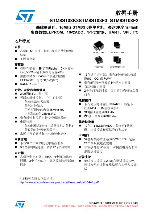
···16-bit generalOC or PWM)with3CAPCO···RAM:memory:128bytes of true data EEPROM;·endurance up to100000write/erase cycles ·Window watchdog and independent watchdog ··I C interface up to400Kbit/s···Flexiblepower crystal resonator oscillator -··Highly robust I/O design,immune against current ·-Low power modes STM8S003K3STM8S003F3Value line,16MHz STM8S8-bit MCU,8Kbytes Flash,128bytes data EEPROM,10-bit ADC,3timers,UART,SPI,I²CInterrupt managementNested interrupt controller with32interrupts·Up to27external interrupts on6vectors LQFP327x7TSSOP20UFQFPN203x3FeaturesCore16MHz advanced STM8core with Harvardarchitecture and3-stage pipeline·Extended instruction setMemoriesProgram memory:8Kbytes Flash;data retention20years at55°C after100cyclesClock,reset and supply management2.95to5.5V operating voltageclock control,4master clock sources:·Power management:(wait,active-halt,halt)-Switch-off peripheral clocks individually·Permanently active,reset consumption power-onTimersAdvanced control timer:16-bit,4CAPCOMchannels,3complementary outputs,dead-timeinsertion and flexible synchronization,·8-bit basic timer with8-bit prescaler·Auto wake-up timerCommunications interfacesUART with clock output for synchronousoperation,Smartcard,IrDA,LIN master mode·SPI interface up to8Mbit/s2Analog to digital converter(ADC)10-bit,±1LSB ADC with up to5multiplexedchannels,scan mode and analog watchdogI/OsUp to28I/Os on a32-pin package including21high sink outputsDevelopment supportEmbedded single wire interface module(SWIM)for fast on-chip programming and non intrusivedebuggingJune2012DocID018576Rev31/100Contents STM8S003K3STM8S003F3 Contents1Introduction (7)2Description (8)3Block diagram (9)4Product overview (10)4.1Central processing unit STM8 (10)4.2Single wire interface module(SWIM)and debug module(DM) (10)4.3Interrupt controller (11)4.4Flash program memory and data EEPROM (11)4.5Clock controller (12)4.6Power management (13)4.7Watchdog timers (13)4.8Auto wakeup counter (14)4.9Beeper (14)4.10TIM1-16-bit advanced control timer (14)4.11TIM2-16-bit general purpose timer (15)4.12TIM4-8-bit basic timer (15)4.13Analog-to-digital converter(ADC1) (15)4.14Communication interfaces (16)4.14.1UART1 (16)4.14.2SPI (17)4.14.3I²C (17)5Pinout and pin description (18)5.1STM8S003K3LQFP32pinout and pin description (18)5.2STM8S003F3TSSOP20/UFQFPN20pinout and pin description (21)5.2.1STM8S003F3TSSOP20pinout and pin description (21)5.2.2STM8S003F3UFQFPN20pinout (22)5.2.3STM8S003F3TSSOP20/UFQFPN20pin description (22)5.3Alternate function remapping (24)6Memory and register map (25)6.1Memory map (25)6.2Register map (26)6.2.1I/O port hardware register map (26)6.2.2General hardware register map (27)6.2.3CPU/SWIM/debug module/interrupt controller registers (36)7Interrupt vector mapping (39)8Option bytes (41)8.1Alternate function remapping bits (43)2/100DocID018576Rev39.3.9 I C interface characteristics (80)STM8S003K3 STM8S003F3Contents9 Electrical characteristics .....................................................................................469.1 Parameter conditions ..................................................................................................46 9.1.1 Minimum and maximum values .......................................................... 46 9.1.2 Typical values ...................................................................................... 46 9.1.3 Typical curves ..................................................................................... 46 9.1.4 Loading capacitor ................................................................................ 46 9.1.5 Pin input voltage ..................................................................................46 9.2 Absolute maximum ratings ......................................................................................... 47 9.3 Operating conditions ...................................................................................................49 9.3.1 VCAP external capacitor ..................................................................... 50 9.3.2 Supply current characteristics ............................................................. 51 9.3.3 External clock sources and timing characteristics .............................. 60 9.3.4 Internal clock sources and timing characteristics ................................ 62 9.3.5 Memory characteristics .. (64)9.3.6 I/O port pin characteristics .................................................................. 66 9.3.7 Reset pin characteristics ..................................................................... 74 9.3.8 SPI serial peripheral interface ............................................................. 77 29.3.10 10-bit ADC characteristics .................................................................819.3.11 EMC characteristics (85)10 Package information ..........................................................................................8910.1 32-pin LQFP package mechanical data ................................................................... 89 10.2 20-pin TSSOP package mechanical data ................................................................. 90 10.3 20-lead UFQFPN package mechanical data ............................................................9211 Thermal characteristics ......................................................................................9411.1 Reference document ................................................................................................ 94 11.2 Selecting the product temperature range .................................................................9412 Ordering information .......................................................................................... 96 13 STM8 development tools ...................................................................................9713.1 Emulation and in-circuit debugging tools .................................................................. 97 13.2 Software tools ...........................................................................................................97 13.2.1 STM8 toolset ..................................................................................... 98 13.2.2 C and assembly toolchains ...............................................................98 13.3 Programming tools ...................................................................................................9814 Revision history ..................................................................................................99DocID018576 Rev 33/100Table 43. I C characteristics (80)List of tablesSTM8S003K3 STM8S003F3List of tablesT able 1. STM8S003xx value line features ............................................................................................... 8 T able 2. Peripheral clock gating bit assignments in CLK_PCKENR1/2 registers ................................. 13 T able 3. TIM timer features ................................................................................................................... 15 T able 4. Legend/abbreviations for pinout tables.................................................................................. 18 T able 5. LQFP32 pin description ........................................................................................................... 19 T able 6. STM8S003F3 pin description .................................................................................................. 22 T able 7. I/O port hardware register map ............................................................................................... 26 T able 8. General hardware register map.............................................................................................. 27 T able 9. CPU/SWIM/debug module/interrupt controller registers........................................................ 36 T able 10. Interrupt mapping .................................................................................................................. 39 T able 11. Option bytes.......................................................................................................................... 99 T able 12. Option byte description .......................................................................................................... 41 T able 13. STM8S003K3 alternate function remapping bits for 32-pin devices ..................................... 43 T able 14. STM8S003F3 alternate function remapping bits for 20-pin devices ..................................... 44 T able 15. Voltage characteristics .......................................................................................................... 47 T able 16. Current characteristics .......................................................................................................... 47 T able 17. Thermal characteristics ......................................................................................................... 48 T able 18. General operating conditions ................................................................................................ 49 T able 19. Operating conditions at power-up/power-down ..................................................................... 50 T able 20. T otal current consumption with code execution in run mode at V DD = 5 V ............................ 51 T able 21. T otal current consumption with code execution in run mode at V DD = 3.3 V ......................... 52 T able 22. T otal current consumption in wait mode at V DD = 5 V ........................................................... 53 T able 23. T otal current consumption in wait mode at V DD = 3.3 V ........................................................ 53 T able 24. T otal current consumption in active halt mode at V DD = 5 V ................................................. 54 T able 25. T otal current consumption in active halt mode at V DD = 3.3 V .............................................. 54 T able 26. T otal current consumption in halt mode at V DD = 5 V ............................................................ 55 T able 27. T otal current consumption in halt mode at V DD = 3.3 V ......................................................... 55 T able 28. Wakeup times ........................................................................................................................ 56 T able 29. T otal current consumption and timing in forced reset state ................................................... 57 T able 30. Peripheral current consumption ............................................................................................ 57 T able 31. HSE user external clock characteristics ................................................................................ 60 T able 32. HSE oscillator characteristics ................................................................................................ 61 T able 33. HSI oscillator characteristics ................................................................................................. 62 T able 34. LSI oscillator characteristics .................................................................................................. 64 T able 35. RAM and hardware registers ................................................................................................. 64 T able 36. Flash program memory and data EEPROM .......................................................................... 65 T able 37. I/O static characteristics ........................................................................................................ 66 T able 38. Output driving current (standard ports) ................................................................................. 68 T able 39. Output driving current (true open drain ports) ....................................................................... 68 T able 40. Output driving current (high sink ports) ................................................................................. 69 T able 41. NRST pin characteristics ....................................................................................................... 74 T able 42. SPI characteristics .................................................................................................................78 2 T able 44. ADC characteristics ............................................................................................................... 82 T able 45. ADC accuracy with R AIN < 10 kΩ , V DD = 5 V........................................................................ 82 T able 46. ADC accuracy with R AIN < 10 kΩ R AIN , V DD = 3.3 V............................................................. 83 T able 47. EMS data ...............................................................................................................................864/100DocID018576 Rev 3STM8S003K3STM8S003F3List of tablesT able48.EMI data (86)T able49.ESD absolute maximum ratings (87)T able50.Electrical sensitivities (88)T able51.32-pin low profile quad flat package mechanical data (89)T able52.20-pin,4.40mm body,0.65mm pitch mechanical data (91)T able53.20-lead ultra thin fine pitch quad flat no-lead package(3x3)mechanical data (92)T able54.Thermal characteristics (94)T able55.Document revision history (99)DocID018576Rev35/100Figure 41. Typical application with I C bus and timing diagram (84)List of figuresSTM8S003K3 STM8S003F3List of figuresFigure 1. Block diagram .......................................................................................................................... 9 Figure 2. Flash memory organization ................................................................................................... 12 Figure 3. STM8S003K3 LQFP32 pinout ............................................................................................... 18 Figure 4. STM8S003F3 TSSOP20 pinout ............................................................................................. 21 Figure 5. STM8S003F3 UFQFPN20-pin pinout .................................................................................... 22 Figure 6. Memory map .......................................................................................................................... 25 Figure 7. Pin loading conditions ............................................................................................................ 46 Figure 8. Pin input voltage .................................................................................................................... 47 Figure 9. f CPUmax versus V DD ............................................................................................................... 50 Figure 10. External capacitor C EXT ...................................................................................................... 50 Figure 11. Typ I DD(RUN) vs. V DD HSE user external clock, f CPU = 16 MHz ............................................ 58 Figure 12. Typ I DD(RUN) vs. f CPU HSE user external clock, V DD = 5 V ................................................... 58 Figure 13. Typ I DD(RUN) vs. V DD HSI RC osc, f CPU = 16 MHz ................................................................ 59 Figure 14. Typ I DD(WFI) vs. V DD HSE user external clock, f CPU = 16 MHz ............................................. 59 Figure 15. Typ I DD(WFI) vs. f CPU HSE user external clock, V DD = 5 V .................................................... 60 Figure 16. Typ I DD(WFI) vs. V DD HSI RC osc, f CPU = 16 MHz ................................................................ 60 Figure 17. HSE external clock source ................................................................................................... 61 Figure 18. HSE oscillator circuit diagram .............................................................................................. 62 Figure 19. Typical HSI frequency variation vs V DD @ 4 temperatures ................................................. 63 Figure 20. Typical LSI frequency variation vs V DD @ 4 temperatures .................................................. 64 Figure 21. Typical V IL and V IH vs V DD @ 4 temperatures ..................................................................... 67 Figure 22. Typical pull-up resistance vs V DD @ 4 temperatures ........................................................... 67 Figure 23. Typical pull-up current vs V DD @ 4 temperatures ................................................................ 68 Figure 24. Typ. V OL @ V DD = 5 V (standard ports) ............................................................................... 70 Figure 25. Typ. V OL @ V DD = 3.3 V (standard ports) ............................................................................ 70 Figure 26. Typ. V OL @ V DD = 5 V (true open drain ports) ..................................................................... 71 Figure 27. Typ. V OL @ V DD = 3.3 V (true open drain ports) .................................................................. 71 Figure 28. Typ. V OL @ V DD = 5 V (high sink ports) ............................................................................... 72 Figure 29. Typ. V OL @ V DD = 3.3 V (high sink ports) ............................................................................ 72 Figure 30. Typ. V DD - V OH @ V DD = 5 V (standard ports) ...................................................................... 73 Figure 31. Typ. V DD - V OH @ V DD = 3.3 V (standard ports) .................................................................. 73 Figure 32. Typ. V DD - V OH @ V DD = 5 V (high sink ports) ...................................................................... 74 Figure 33. Typ. V DD - V OH @ V DD = 3.3 V (high sink ports) ................................................................... 74 Figure 34. Typical NRST V IL and V IH vs V DD @ 4 temperatures .......................................................... 76 Figure 35. Typical NRST pull-up resistance vs V DD @ 4 temperatures ................................................ 76 Figure 36. Typical NRST pull-up current vs V DD @ 4 temperatures ..................................................... 77 Figure 37. Recommended reset pin protection ..................................................................................... 77 Figure 38. SPI timing diagram - slave mode and CPHA = 0 ................................................................. 79 Figure 39. SPI timing diagram - slave mode and CPHA = 1 ................................................................. 79 Figure 40. SPI timing diagram - master mode (1) ..................................................................................80 2 Figure 42. ADC accuracy characteristics .............................................................................................. 84 Figure 43. Typical application with ADC ............................................................................................... 85 Figure 44. 32-pin low profile quad flat package (7 x 7) ......................................................................... 89 Figure 45. 20-pin, 4.40 mm body, 0.65 mm pitch .................................................................................. 90 Figure 46. 20-lead ultra thin fine pitch quad flat no-lead package outline (3x3) ................................... 92 Figure 47. STM8S003x value line ordering information scheme ..........................................................966/100DocID018576 Rev 3· · For informationto the STM8S Flash programming manual (PM0051).internal Flash memory· For information on the protocol and debug module user manual (UM0470). to the STM8· For information on the STM8 core, please refer to the STM8 CPU programming manualSTM8S003K3 STM8S003F3Introduction1IntroductionThis datasheet contains the description of the device features, pinout, electrical characteristics, mechanical data and ordering information.For complete information on the STM8S microcontroller memory, registers and peripherals, please refer to the STM8S microcontroller family reference manual (RM0016).on programming, erasing and protection of the please referdebug and SWIM (single wire interface module) refer SWIM communication(PM0044).DocID018576 Rev 37/100Multipurpose timer (TIM1), SPI, I C, UARTDescription2STM8S003K3 STM8S003F3DescriptionThe STM8S003x value line 8-bit microcontrollers feature 8 Kbytes Flash program memory, plus integrated true data EEPROM. The STM8S microcontroller family reference manual (RM0016) refers to devices in this family as low-density. They provide the following benefits: performance, robustness, and reduced system cost.Device performance and robustness are ensured by integrated true data EEPROM supporting up to 100000 write/erase cycles, advanced core and peripherals made in a state-of-the art technology, a 16 MHz clock frequency, robust I/Os, independent watchdogs with separate clock source, and a clock security system.The system cost is reduced thanks to high system integration level with internal clock oscillators, watchdog and brown-out reset.Full documentation is offered as well as a wide choice of development tools.Table 1: STM8S003xx value line featuresDevice Pin countMaximum number of GPIOs (I/Os) Ext. interrupt pins Timer CAPCOM channels Timer complementary outputs A/D converter channels High sink I/OsSTM8S003K3 32 28 27 7 3 4 21STM8S003F3 20 16 16 7 2 5 12 Low density Flash program memory (bytes) 8K 8K RAM (bytes)True data EEPROM (bytes) 1K 128 (1)1K 128 (1)2Peripheral setwindow WDG,independent WDG, ADC, PWM timer (TIM2), 8-bit timer (TIM4)(1) Without read-while-write capability.8/100DocID018576 Rev 3A d d r e s s a n d d a t a b u sSTM8S003K3 STM8S003F3Block diagram3Block diagramFigure 1: Block diagramReset blockClock controllerXTAL 1-16 MHzResetSingle wire debug interf.400 Kbit/s8 Mbit/sResetPORBORSTM8 coreDebug/SWIMI2CSPIDetectorClock to peripherals and coreRC int. 16 MHzRC int. 128 kHzWindow WDGIndependent WDG8-Kbyte program Flash 128-bytedata EEPROM1-KbyteRAMUp to4 CAPCOM channels +3LIN master SPI emul.UART116-bit advanced control timer (TIM1)16-bit general purposetimer (TIM2)complementaryoutputsUp to3 CAPCOMchannels8-bit basic timerUp to 5 channels1/2/4 kHzbeepADC1BeeperDocID018576 Rev 3(TIM4)AWU timer9/100· · Xand read-modify-write type data manipulations addressing modes with or without offset · · Indexed indirect addressing mode for look-up tables located anywhere in the address ·Product overviewSTM8S003K3 STM8S003F344.14.210/100Product overviewThe following section intends to give an overview of the basic features of the device functional modules and peripherals.For more detailed information please refer to the corresponding family reference manual (RM0016).Central processing unit STM8The 8-bit STM8 core is designed for code efficiency and performance.It contains 6 internal registers which are directly addressable in each execution context, 20 addressing modes including indexed indirect and relative addressing and 80 instructions.Architecture and registers Harvard architecture· 3-stage pipeline · 32-bit wide program memory bus - single cycle fetching for most instructionsand Y 16-bit index registers - enabling indexed · 8-bit accumulator · 24-bit program counter - 16-Mbyte linear memory space · 16-bit stack pointer - access to a 64 K-level stack · 8-bit condition code register - 7 condition flags for the result of the last instructionAddressing20 addressing modesspace · Stack pointer relative addressing mode for local variables and parameter passingInstruction set80 instructions with 2-byte average instruction size· Standard data movement and logic/arithmetic functions · 8-bit by 8-bit multiplication · 16-bit by 8-bit and 16-bit by 16-bit division · Bit manipulation · Data transfer between stack and accumulator (push/pop) with direct stack access · Data transfer using the X and Y registers or direct memory-to-memory transfersSingle wire interface module (SWIM) and debug module (DM)The single wire interface module and debug module permits non-intrusive, real-time in-circuit debugging and fast memory programming.DocID018576 Rev 3· · 128 bytes ofbyte area EEPROM· ·STM8S003K3 STM8S003F3Product overviewSWIMSingle wire interface module for direct access to the debug module and memory programming. The interface can be activated in all device operation modes. The maximum data transmission speed is 145 bytes/ms. Debug moduleThe non-intrusive debugging module features a performance close to a full-featured emulator. Beside memory and peripherals, also CPU operation can be monitored in real-time by means of shadow registers.R/W to RAM and peripheral registers in real-time· R/W access to all resources by stalling the CPU · Breakpoints on all program-memory instructions (software breakpoints) · Two advanced breakpoints, 23 predefined configurations4.34.4Interrupt controller· Nested interrupts with three software priority levels · 32 interrupt vectors with hardware priority · Up to 27 external interrupts on 6 vectors including TLI · Trap and reset interruptsFlash program memory and data EEPROM· 8 Kbytes of Flash program single voltage Flash memorytrue data User optionWrite protection (WP)Write protection of Flash program memory and data EEPROM is provided to avoid unintentional overwriting of memory that could result from a user software malfunction.There are two levels of write protection. The first level is known as MASS (memory access security system). MASS is always enabled and protects the main Flash program memory, the data EEPROM, and the option bytes.T o perform in-application programming (IAP), this write protection can be removed by writing a MASS key sequence in a control register. This allows the application to modify the content of the main program memory and data EEPROM, or to reprogram the device option bytes. A second level of write protection, can be enabled to further protect a specific area of memory known as UBC (user boot code). Refer to the figure below.The size of the UBC is programmable through the UBC option byte, in increments of 1 page (64-byte block) by programming the UBC option byte in ICP mode. This divides the program memory into two areas: Main program memory: 8 Kbytes minus UBC· User-specific boot code (UBC): Configurable up to 8 KbytesThe UBC area remains write-protected during in-application programming. This means that the MASS keys do not unlock the UBC area. It protects the memory used to store the bootDocID018576 Rev 311/100。
毕业设计说明书数字式交流毫伏表电路的设计专业电气工程及其自动化学生姓名姜晓天班级BM电气082学号0851402211指导教师成开友完成日期2012年5月22日数字式交流毫伏表电路的设计摘要:当今社会是数字化的社会,是数字集成电路广泛应用的社会。
数字集成电路本身在不断地进行更新换代。
它由早期的电子管、晶体管、小中规模集成电路,发展到超大规模集成电路(VLSIC)以及许多具有特定功能的专用集成电路。
本文设计的电路分为模拟和数字两个部分,具有量程自动转换功能。
输入信号经过输入通道进入放大器部分,经过放大后,由AC/DC转换电路转换为与交流电压有效值相等的直流电压。
该直流电压经过V/F转换电路输出相应的频率量,然后计数器部分在秒脉冲的控制下进行技术测量,最后显示出读数,从而完成电压的测量。
本文所设计的数字式交流毫伏表的显著特点是测量范围宽,可测范围在500V 以下,最大分辨率为0.01mV,且可以实现量程自动转换,操作简单,使用方便。
电压表还具有在一定测量范围内自动选择量程的功能,从而可以快速,方便,准确地测量电压。
关键词:A/D转换;V/F转换;量程自动转换;计数器Digital AC millivoltmeter circuit designAbstract:Today's society is the digital society , the society of a wide range of applications of digital integrated circuits . Digital integrated circuits constantly upgrading . By the early tubes, transistors , small - scale integrated circuits developed to ultra - LSI ( VLSIC ) as well as many ASIC has a specific function .In this paper, the design of the circuit is divided into analog and digital two parts , with a range automatic conversion . After the input channel , the input signal into the amplifier section, after amplification by AC / DC converter circuit to convert the DC voltage equal to the AC voltage rms . The output frequency of the DC voltage conversion circuit through the V / F , then the counter part of the second pulse control techniques to measure , and finally show the reading , thus completing the measurement of the voltage .Designed digital AC millivoltmeter notable feature is the wide measuring range can be measured in the range below 500V , the maximum resolution of 0.01mV , and can realize automatic range conversion , simple operation, easy to use . The voltmeter also has automatically selected range in a certain measuring range of functions , which can be fast , convenient and accurate measurement of voltage .Key Words: A / D converter ; V / F conversion ; automatic conversion range ; counter盐城工学院本科生毕业设计说明书( 2012)目录1.概述 (1)2. 设计总体方案 (2)3.模拟部分设计 (2)3.1 输入通道的设计 (2)3.2 反相放大器的设计 (3)3.3A/D 转换部分的设计 (4)4.量程自动转换电路的设计 (6)4.1 模拟比较器 (6)4.2 量程寄存器 (8)4.3 量程开关 (10)4.4 译码器 (11)5. 数字部分 (15)5.1 V/F转换器AD650 (15)5.2 计数器74LS90 (17)5.3 锁存器74LS273 (18)5.4 秒脉冲发生器 (19)5.4 控制电路 (21)6. 译码显示部分 (23)7. 电源部分 (24)8. 结束语 (26)致谢 (27)附录 (29)附录1:程序清单 ............................................................................................... 错误!未定义书签。
数显三相电流电压表使用说明书一、概述该产品是采用单片机设计而成的最新产品,具有以下特点:1、正四位显示,2、高位转换,精度高。
3、单片机设计,抗干扰性能强4、具有多项菜单编程,可灵活操作5、量程准确,性能可靠6、功能扩展方便,可扩展报警输出口及可编程单元。
二、通用技术指标、工作电源:±、功耗:<.5、精度:测量级、工作环境:℃℃、储存环境:℃℃、绝缘:大于Ω三、按键说明●功能选择键●键:移位键●▲键:数据键四、显示说明●电流表显示方式说明:-当显示值 < 时,显示三位小数,即:-当≤显示值 < 时,显示二位小数,即:-当≤显示值 < 时,显示一位小数,即:-当≤显示值 < 时,不显示小数位,即:-当显示值≥时,指示灯点亮,显示为:●电压表显示方式说明:-当显示值 < 时,显示一位小数,即:-当≤显示值 < 时,不显示小数位,即:-当≤显示值 < 时,指示灯点亮,显示为:-当≤显示值 < 时,指示灯点亮,显示为:-当显示值≥时,指示灯点亮,显示为:五、参数设置持续按下(初始密码为“”)●数码管显示“――――”,按任意键,数码管闪烁显示“”。
●操作按键,依次输入密码:键:由左至右选择闪烁位▲键:从~改变闪烁位的数值。
键:确认数据,校验已输入的密码值。
密码输入正确时,进入参数设置程序:三相变比同时修改:●三排数码管及指示灯同时闪烁显示当前电压表/电流表的比例系数●操作键,选择需要修改的数字位(闪烁位)●操作▲键,修改当前闪烁位的数值例:倍率应设置●持续按下键超过秒,确认并保存当前数据,退出操作。
●短时按下键,确认当前数据,进入步骤:仅修改相变比.(注:三相变比相同,无需操作此项)六、运输存贮与保修期限产品在运输和拆封时不应受到剧烈冲击,并根据《仪器仪表包装通用技术条件》规定运输和存贮。
库存和保管应在原包装条件下存放在支架上,叠放高度不应超过层。
基于STM8的数字电压表设计摘要:本产品是一款自动调整量程的数字电压表,其采用STM8单片机对数据进行处理并输出;电压值采用单片机自带的10位ADC电路进行采集,即化简了电路的复杂性,又降低了成本、提高了精度。
当采集电压高于ADC的采集极限时,放大器PGA对量程自动调节,省去了手动调节量程的过程。
电路中的放大器PGA设计方法是使用数字电位器作为运算放大电路的反馈电阻,调节运算放大器的放大倍数,使输入的ADC电压值满足要求。
如果输入电压没有达到要求则根据实际情况自动调节数字电位器,即调整运算放大器的放大倍数使之满足要求。
实际值根据放大器的放大倍数计算得出,并通过数码管显示,可直观的读取测量结果。
关键词:STM8控制器电压测量量程自动调整1引言电压作为电子产品的最重要的参数,所以产品在使用过程中需要对其进行测量、显示,以此来判断该产品的工作状态,电压表应运而生。
电压表就是将无形的电压值转变成可以直接看到数值的电压测量工具,是电压测量的必备工具。
电压表分为数字式和模拟式,本产品的数字式电压表相比模拟式电压表具有精度高、速度快、自动化程度高、抗干扰能力强和方便读数等特点。
1总体方案本产品的核心是STM8控制芯片。
STM8控制器芯片上有独立的10位测量精度的ADC电路,电压采集直接通过芯片上的ADC电路进行采集。
在STM8最小系统电路中外部时钟可以省略,使用芯片内部的RC振荡器产生16M的时钟。
程序采用SWD进行下载,下载完成后直接运行,无需进行热启动。
此外STM8可以进行在线调试,通过仿真器对程序运行过程进行调试。
本产品使用STM8S003F3P6单片机,该型号封装为TSSOP20,封装尺寸更小。
STM8单片机支持5V和3.3V电平,兼容性更高。
主要包括量程转换电路PGA、STM8单片机和数码管显示电路。
量程转换电路是通过放大器对输入的电压值进行调节,将测量值转换为合适采集值。
通过程序控制数字电位器改变阻值,对输入的信号进行放大或者衰减,使输出信号始终保持在ADC量程的2/3到满量程之间,这样既可以使低电压有较高测量精度,又可以使高电压不会对ADC造成损坏。
交流毫伏表的使用常用的单通道晶体管毫伏表,具有测量交流电压、电平测试、监视输出等三大功能。
交流测量范围是100nV~300V、5Hz~2MHz,共分1、3、10、30、100、300mV,1、3、10、30、100、300V共12档;电平dB刻度范围是-60~+50dB。
1、.工作原理晶体管毫伏表由输入保护电路、前置放大器、衰减放大器、放大器、表头指示放大电路、整流器、监视输出及电源组成。
输入保护电路用来保护该电路的场效应管。
衰减控制器用来控制各档衰减的接通,使仪器在整个量程均能高精度地工作。
整流器是将放大了的交流信号进行整流,整流后的直流电流再送到表头。
监视输出功能主要是来检测仪器本身的技术指标是否符合出厂时的要求,同时也可作放大器使用。
2、.使用方法(1)开机前的准备工作:①将通道输入端测试探头上的红、黑色鳄鱼夹短接;②将量程开关选最高量程(300V)。
(2)操作步骤:①接通220V电源,按下电源开关,电源指示灯亮,仪器立刻工作。
为了保证仪器稳定性,需预热10秒钟后使用,开机后10秒钟内指针无规则摆动属正常;②将输入测试探头上的红、黑鳄鱼夹断开后与被测电路并联(红鳄鱼夹接被测电路的正端,黑鳄鱼夹接地端),观察表头指针在刻度盘上所指的位置,若指针在起始点位置基本没动,说明被测电路中的电压甚小,且毫伏表量程选得过高,此时用递减法由高量程向低量程变换,直到表头指针指到满刻度的2/3左右即可;③准确读数。
表头刻度盘上共刻有四条刻度。
第一条刻度和第二条刻度为测量交流电压有效值的专用刻度,第三条和第四条为测量分贝值的刻度。
当量程开关分别选1mV、10mV、100mV、1V、10V、100V档时,就从第一条刻度读数;当量程开关分别选3mV、30mV、300mV、3V、30V、300V时,应从第二条刻度读数(逢1就从第一条刻度读数,逢3从第二刻度读数)。
例如:将量程开关置“1V”档,就从第一条刻度读数。
若指针指的数字是在第一条刻度的“0.7”处,其实际测量值为0.7V;若量程开关置“3V”档,就从第二条刻度读数。
1简介
数显交流电压表芯片采用ST公司低成本、高性价的STM8S003F3,并固化数显表采样算法,显示程序而成。
STM8S003F3直接采样交流电压信号,并进行数字滤波器,有效值算法算出电压有效值,刷新速度快。
采用本芯片的数显电压表方案具备成本低,外围电路简单,体积小,生产方便。
芯片自带校准功能,校准方便,校准速度快等特点。
STM8S003F3是ST公司的一颗低成本、性价比非常的单片机,基于高级STM8内核,具有3级流水线的哈佛。
此芯片具体有8K FLASH,1K RAM,128B EEPROM,具有中断管理,多路定时器,带UARTA、SPI、I2C通信接口,10位AD转换口,很强的IO倒灌电流能力,支持单线接口模块(SWIM)和调试模块(DM),可以方便地进行在线编程和非侵入式调试。
2芯片内部框图
3引脚定义
引脚说明
4电气特性
极限参数
5封装说明
数显交流电压表芯片使用手册 6参考设计
6 / 7
数显交流电压表芯片使用手册
说明:
1)使用共阳数码管,COM1,COM2,COM3上的电流不得大于10mA;
2)电压采样至少采用5个以上的1206电阻或7个0603电阻进行分压,以避免浪涌后,电
阻值发生变化;
3)如对计量电压的精度,稳定度,温漂有更高要求,请使用专门的稳压器(比如TL431)
进行稳压。
4)阻容降压电路必须使用630V以上CBB电容或者安规电容,但电压测量范围比较小时,
可以降低电容的,当然也可采用其他供电方式!
7校准说明
使用一个220V交流电压源(精度要求不高时,可以使用普通的交流稳压源)给电压表供电,对地短接FACTORY信号,约2秒左右,当LED显示220V即表示校准成功。
8关于固化程序STM8S003F3芯片的供货
第100-第5000片2元/片(不含STM8S003F3芯片,仅固化程序的费用)
第5001-第20000片1元/片(不含STM8S003F3芯片,仅固化程序的费用)
第20001片及以上0.5元/片(不含STM8S003F3芯片,仅固化程序的费用)
注:
1)多次采购可累计计算片数(比如第一次采购了5000片,则价格为2元/片),第2
次有采购了5000片,这价格为1元/片;累计计算片数时,只针对同一个人或公
司!
2)以上报价不含税;
3)更多信息可访问淘宝店铺:。