TBLM脉冲使用说明书
- 格式:pdf
- 大小:865.61 KB
- 文档页数:14

I N S T R U C T I O N M A N U A LModels:3” (D-750), 3” (D-1000)(Extended flow range),4”(D-1500)&4"(D-2500)(Extended flow range)Large capacity positive displacementPulse FlowmetersOVAL GEARIndex / contents 11.0General Page1.1 Overview 21.2 Operating principal 21.3 Specifications 32.0 Installation2.0 Mechanical installation 42.0.1 Meter & totaliser orientation 42.1 Flow conditioning & locations 52.2 Electrical Installation 52.2.1 Instrument Cable 62.2.2 Hazardous Area Wiring 62.3 Pulse output selection for pulse meters 62.3.1 Hall effect sensor output 62.3.2 Reed switch output 62.4 Calibration K-factor 63.0 Commissioning 74.0Maintenance4.0 Maintenance 84.1 Disassembly of meter & exploded view 84.2 Inspection 94.3 Re-assembly of meter 94.4 Spare parts list 105.0 Fault Finding 115.1 Trouble shooting 122 General1.1 OverviewThe Oval Gear meter is a precise positive displacement flowmeter incorporating a pair of oval geared rotors. These meters are capable of measuring the flow of a range of clean liquids such as fuels, fuel oils & lubricating liquids.The flowmeter is available with a pulse output only for safe or hazardous areas. The meter also has a flow rate register option with either RT40 (option E) for safe areas or an intrinsically safe RT12 (option I) for hazardous areas. Both these totalisers have pulse output capabilities of interfacing to most monitoring and controlinstrumentation. The RT12 instrument also has monitoring and control output options 4-20mA, scaled pulse and flowrate alarms.Both RT12 and RT40 options have multiple display units (kgs, Litres, lbs, Gal and m³) and can show instantaneous flow rate and total flow values1.2 Operating PrincipleThe Oval gear are positive displacement flowmeters where the passage of liquid causes two oval geared rotors to rotate within a precision measuring chamber and with each rotation a fixed volume of liquid is displaced passing through the meter. Magnets embedded within the rotors initiate a high resolution pulse train output. The pulse output can be wired directly to process control and monitoring equipment or can be used as an input to instruments supplied with or fitted directly to the meter.The benefits of this technology allow precise flow measurement and dispensing of most clean liquids irrespective of their conductivity, with other liquid characteristics having nil or minimal effect on meter performance. This metering technology does not require flow profile conditioning as required with alternative flow technologies making the installation relatively compact and low cost.OPERATION :Liquid travels around the crescentshaped chambers created by therotational movement of the rotorsliquid exits the measuring chamber liquid in transit flow liquid entering measuring chamberSpecifications 31.3 Specifications4 Installation2.0 Mechanical Installation Prior to installing the meter check :•The fluid is compatible with the meter materials of construction using appropriate information such as fluid compatibility charts and site experience.•The application and process conditions are compatible with the meter specifications. Minimum and maximum flows are within the meter specified range including any in-situ cleaning processes. Whenmetering viscous liquids the maximum allowable flow may need to be reduced to ensure the pressuredrop across the meter does not exceed 100 kPa (1 Barg, 15 PSIG).•The process temperature and pressure does not exceed meter ratings.•The meter is not exposed to process temperatures and pressures that will cause the liquid medium to gasify (flash) within the meter.2.0.1 Flow Conditioning and LocationsStrainer : It is recommended to INSTALL a 40mesh (350 micron) strainer immediately upstream of (prior to) the meter. Strainers are available from the factory.Flow conditioning : The flowmeter does not require any flow conditioning, therefore straight pipe runs before or after the meter are not required. If required, the pipe size about the meter can be altered to suit the installation.Locations : The flowmeter is preferred to be fitted upstream of any flow control and/or shut off valve, this prevents free discharge from the meter and minimizes the risk of drainage and air entrapment which can result in erroneous readings or damage the meter on start up.Process or safety critical meters should be installed in a by-pass section of pipe with isolation valves to enable the meter to be isolated and serviced as required. A by-pass installation also allows purging of the system during commissioning (see Commissioning).The meter must be appropriately rated and is typically located downstream (on the discharge side) of the pump.If mounted outdoors ensure a suitable watertight gland or plug is used to seal any open electrical entries. In humid environments take precautions to avoid condensation build up within the electrical and/or instrument enclosure. It is good wiring practice for conduits to be connected from the bottom of an entry port, in this way condensation will gravitate away from any terminal housing.Fluid state : Fluid entering the meter must remain a liquid at all times so protect the meter to avoid solidification or gelling of the metered medium. If meters are to be trace heated or jacketed in any way the maximum temperature rating of the meter must not be exceeded. Size the meter to avoid gasification of volatiles (flashing) within the liquid due to the pressure drop experienced within the system or within the meter.Hydraulic shock : If pressure surges or hydraulic shock of any kind is possible, the system upstream of the meter must be fitted with a surge suppressor or pressure relief valve to protect the meter from damage. High frequency flow pulsations can damage the meter. Such pulsations can be caused by the injection profile in diesel engines. Most pulsations are removed with the installation of a suitable pulsation dampener.Installation 5 2.1 Meter & totaliser orientationThe flowmeter MUST be mounted so that the rotor shafts are in a horizontal plane. This is achieved by mounting the meter so that the digital display is facing the user in a horizontal direction, it should never point towards the sky or towards the ground. If installed incorrectly the weight of the rotors will bear down on the base of the measuring chamber, leading to inaccuracy and meter damage and failure.Liquid can flow into the meter from either a horizontal or vertical direction. For vertical flow installations the most common orientation is for the liquid to rise through the meter (i.e. travel from bottom to top) to assist in air or entrained gas elimination. The meter operation is independent of the liquid flow direction thus there is no markings for inlet or outlet.Given the size and weight of these meters, it is recommended that any 3” or 4” meters have adequate support so that there is no excessive pressure on the process connections. Failure to support these meters during the installation process can result in structural damage to the flowmeter’s threaded connections/flanges during normal operation.2.2 Electrical InstallationAs a default the meter and totalizer is wired at the factory with the reed output pre-wired and DIP switches set for an integral rate/totaliser allowing self-powered operation of the instrument displays.The output(s) and function(s) available from a meter fitted with an integral instrument depends on the model of the instrument fitted and may include meter pulse repeater, pre-scaled pulse output, 4-20mA flow output or flowrate alarms.Refer to the option in the meter model number and relevant instrument manual. Unless programming details were provided at time of order the instrument program will contain factory default parameters. Integral instruments will however be programmed with the relevant calibration factor (K factor or scale factor) for the meter.Factory default settings can be found in the instrument instruction manual and it should be noted all output(s) are6 Installation2.2.1 Instrument Cable Twisted pair low capacitance shielded instrument cable 7 x 0.3mm (0.5mm²) should be used for electrical connection between the flowmeter and remote instrumentation, use Belden® number 9363 or similar. The cable drain or screen should be terminated on a DC COMMON or a specifically assigned shield termination at the readout instrument end only in order to protect the transmitted signal from mutual inductive interference. IMPORTANT, tape off & isolate the shield at the flowmeter end of the cable.The cable should not be run in a common conduit or parallel with power and high inductive load carrying cables as power surges may induce erroneous noise transients onto the transmitted pulse signal or cause damage to the electronics. Run the cable in separate conduit or with other low energy instrument cables. The maximum transmission distance is typically 1000m (3300 Ft).2.2.2 Hazardous area wiring Intrinsically safe wiring including using the reed switch pulse output as simple apparatus, wiring to an Intrinsically Safe Instrument must be undertaken in accordance with the rules, regulations and requirements applying to the territory in which the meter is being installed. The meters should only be connected by qualified staff, the qualified staff must have knowledge of protection classes, regulations & provisions for the apparatus in hazardous areas.If the flowmeter is fitted with an intrinsically safe instrument refer to the appropriate manual & I.S. supplement for wiring of the instrument inputs and outputs.2.3 Pulse Output selection for pulse meters Two types of output are available on each meter, open collector from Hall Effect sensors or reed switch contact. Each output type is linearly proportional to volumetric flow and each pulse is representative of an equal volume of liquid.2.3.1 Hall Effect Sensor Pulse Output The Hall Effect Sensor is a high resolution solid state 3 wire device providing an un-sourced, open collector, NPN transistor output. The term “un-sourced” means that no voltage is applied to the output from within the flowmeter, it must be pulled to a ‘high’ or ‘on’ state by between 5~24Vdc supplied from an external source, typically the receiving instrument.2.3.2 Reed Switch Pulse Output The reed switch output is a two wire normally open SPST voltage free contact ideal for installations without power or for use in hazardous area locations when Intrinsically Safe (I.S.) philosophy is adopted. Note: when using the reed switch output the liquid temperature must not change at a rate greater than 10ºC per minute (50ºF per minute).In general the reed switch life will exceed 2 billion actuations when switching less than 5Vdc @10mA as is the case when combined with the RT12 and RT40 instruments. 2.4 Meter Calibration Factor (K or scale Factor) Each flowmeter is individually calibrated and has the number of pulses per unit volume (eg pulses per litre or pulses per US gallon) entered into the program of the instrument. Please refer to relevant instrument manual for programming details. Nominal figures are shown in the specification section of this manual. For more accurate metering we recommend using the calibrated K factor. Calibration certification is available upon request from your distributor.Commissioning 73.0 Commissioning Once the meter has been mechanically installed the meter is ready for commissioning.The meter must NOT be run until the pipework is flushed of foreign matter, more often than not foreign matter is present after pipework fabrication or modification; weld slag, grinding dust, sealing tape & compound &/or surface rust are most common offenders.Flushing can be undertaken by utilizing a by-pass or removing the meter from the pipework. If neither is practical then the meter rotors must be removed prior to flushing (refer to Maintenance section of this manual for disassembly).After flushing or following long periods of shutdown the meter must be purged of air/vapour. This can be achieved by allowing the liquid to flow through the meter at a slow rate until all air/vapor is displaced. Never run the meter above its maximum flow or exceed 100kpa (1 bar, 15psi) pressure drop across the meter. Now the meter is ready for its operation to be confirmed by ensuring correct indication on the mechanical display. Refer if necessary to fault finding section of this manual. flowmeter isolation valve isolation valve Open downstream valve last4.0 Maintenance Adhering to the installation instructions in this manual should ensure your meter provides the required operational performance. These are mechanical meters and a periodic maintenance and inspection regime will maximize the operational availability of the meter.The frequency of maintenance depends on the application factors including liquid lubricity and abrasiveness and operational factors such as flowrate and temperature.BEFORE undertaking meter maintenance ensure the following :Associated alarm(s) or control output(s) are isolated so not to affect the process.The meter is isolated from any source of supply of liquid upstream or downstream.The meter is depressurized and liquid drained from the meter.4.1Disassembly of Pulse meter (Refer Exploded View)The meter is fitted with an integral instrument the instrument display assembly must be removed if required to gain access to the instrument terminal connections, instrument battery or pulse output board. This is achieved by:1.Undo the bezel screws and separate the display assembly from its base. Do not stress or damage thewires that connect the display assembly to the meter output. Take care not to misplace or damage O-ring(s).The pulse output board can now be accessed.2.To remove the pulse output board, first undo the screws that fix the instrument base to the flowmeter(Refer Exploded View).If required to gain access to the oval geared rotors undo the 8 body screws (5), carefully pry the meter body apart avoiding misplacing or damaging the O-ring (3) and rotors (2).Maintenance 94.2 Inspection (refer Exploded View)Inspect O-rings (3) for damage, chemical attack, deformity or any form. Remove, inspect & clean the rotors (2). Check the measuring chamber (1) for damage or scoring & redress if necessary, the rotor shafts should NOT be loose or able to be rotated.4.3 Re-assembly of meter (refer Exploded View)When re-installing the rotors (2) all four magnets MUST be visible when both rotors are in place. Both rotors will only engage correctly if fitted precisely at an orientation of 90 degrees to each other. Rotate the rotors slowly by hand to ensure they are correctly fitted at the same time check the rotor shafts & rotor bearings for wear.Fit the O-ring (3) into the groove and assemble the two parts of the meter, the body (1) & cap (4) align with a location pin.Fit the body cap screws (5) and tighten in a star sequence then carryout a final tighten in the same sequence to a firm torque. This sequence and procedure ensures the meter bodies are assembled correctly and evenly. Fit the pulse output board and instrument as appropriate.This sequence and procedure ensures the meter bodies are assembled correctly and evenly. Once completed,10 Maintenance 4.4 Spare PartsFault finding 11 5.0 Fault Finding Pulse meters have two distinct sections: the mechanical wetted section housing the rotors and the electrical section housing the pulse output board.Meters fitted with integral instruments have these two sections plus the instrument.The aim of fault finding is to trace the source of the fault to one of these sections.If a fault is traced to an instrument section, refer to the relevant instruction manual.Below are basic fault finding steps. Also refer to Trouble Shooting Guide on following page.Step 1 - Check application, installation and setup.Refer to Mechanical Installation section for installation and application factors that may affect the meter operation including pulsation and air entrainment or incorrect meter selection including incorrect flow rate, temperature and pressure or materials compatibility. Refer to Electrical Installation for correct wiring.Step 2 - Check for blockages.The most common cause of fault/unsatisfactory meter operation, particularly for new or altered installations, is due to blockage within the system or meter caused by foreign particles such as weld slag, sealing tape or compound, rust, etc.Step 3 - Ensure flow is present.No flow or lower than normal minimum flow may be attributed to a blocked strainer, jammed or damaged rotors within the flowmeter, malfunctioning pump, closed valves or low liquid level in feeder tank.Step 4 - Ensure oval gears within meter are rotating.Rotation of the oval gears can be heard by holding a screw driver blade to the meter body and pressing the handle hard against the ear lobe. If necessary test the meter with the flow turned off and turned on to familiarize yourself with the audible rotation signature.Step 5 - Ensure pulses are being generated during flowing conditions.A multimeter is often not fast enough to distinguish the pulse train from the reed switch or Hall Effect sensor. An oscilloscope will allow you to view the output pulse train. When viewing the Hall effect sensor pulse ensure a pull up resistor is installed between the pulse output and the supply voltage (refer electrical installation).Step 6 - Confirm Instrument Operation.If an associated instrument is connected to the flowmeter confirm its operation by simulating a pulse input onto the flow input terminals. In most instances a contact closure on the flow input terminals is an adequate simulation.12 Trouble shooting5.1 TROUBLE SHOOTINGNotes:IM-D-750~D-2500-Pulse 3216© 2017 Great Plains Industries, Inc., All Rights Reserved.Great Plains Industries, Inc. / 888-996-3837 / 。
第1篇一、产品概述脉冲针灸治疗仪是一种集传统针灸与现代科技于一体的医疗设备,通过模拟传统针灸的刺激方式,结合现代电子技术,对人体的穴位进行刺激,以达到疏通经络、调和气血、缓解疼痛、调节生理功能等治疗效果。
本产品适用于各种慢性疼痛、神经痛、肌肉劳损、关节炎、颈椎病、腰椎病等疾病的治疗和调理。
二、产品特点1. 模拟传统针灸:脉冲针灸治疗仪采用微电脑控制,模拟传统针灸的手法,刺激穴位,安全可靠。
2. 多种刺激模式:根据不同疾病和患者需求,提供多种刺激模式,如疏密波、断续波、疏密断续波等。
3. 自动定时:治疗时间可根据需要设定,避免长时间治疗对患者造成不适。
4. 安全保护:具有过载保护、短路保护等功能,确保使用安全。
5. 操作简便:操作界面直观易懂,操作简便,老人和儿童也可轻松使用。
三、适用范围1. 慢性疼痛:如颈椎病、腰椎病、肩周炎、关节炎、风湿性关节炎等。
2. 神经痛:如坐骨神经痛、三叉神经痛、带状疱疹后遗神经痛等。
3. 肌肉劳损:如腰肌劳损、肩背肌肉劳损、腿痛等。
4. 消化系统疾病:如胃痛、肠炎、便秘等。
5. 妇科疾病:如痛经、月经不调等。
四、使用方法1. 检查设备:使用前请检查设备外观是否完好,如有损坏,请及时联系售后服务。
2. 选择刺激模式:根据疾病和患者需求,选择合适的刺激模式。
3. 调整强度:根据个人感觉调整刺激强度,以患者能忍受为宜。
4. 穴位定位:根据疾病选择相应的穴位,如颈椎病可选用风池、大椎、肩井等穴位。
5. 治疗操作:将电极片贴在穴位上,开启治疗仪,开始治疗。
治疗过程中,如感觉不适,请立即关闭治疗仪。
6. 治疗时间:每次治疗时间约为30分钟,每天1-2次,具体治疗次数根据病情和患者需求而定。
五、注意事项1. 使用前请确保治疗仪处于干燥、通风的环境中。
2. 治疗时请保持电极片与皮肤接触良好,避免脱落。
3. 治疗过程中,如感觉不适,请立即关闭治疗仪。
4. 治疗过程中,避免电极片受到碰撞、挤压等外力作用。

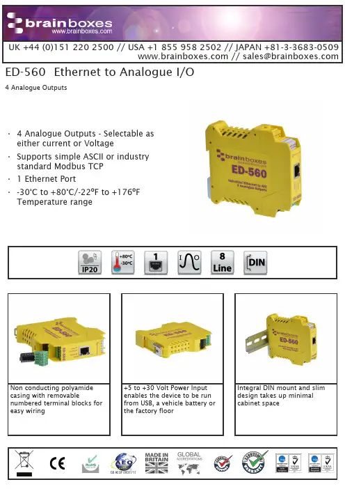
Integral DIN mount and slim design takes up minimal cabinet space+5 to +30 Volt Power Input enables the device to be run from USB, a vehicle battery or the factory floorNon conducting polyamide casing with removablenumbered terminal blocks for easy wiringGB AEOF 00031/11Ethernet to Analogue I/O• 4 Analogue Outputs - Selectable as either current or Voltage • Supports simple ASCII or industry standard Modbus TCP • 1 Ethernet Port• -30°C to +80°C/-22ºF to +176ºF Temperature range4 Analogue OutputsED-560ConnectorsScrew Terminals 3.5mm pitchWire Thickness #22 - #14, 0.5mm 2-2.5mm 2Power SupplyPower Supply input Unregulated +5V to +30Volts DC, reverse polarity protection Isolation1500V RMS Magnetic isolation from Ethernet EnvironmentalOperating Temperature -30o C to +80o C / -22ºF to +176ºF Storage Temperature-40o C to +85o C / -40ºF to +185ºF Ambient Relative Humidity 5 to 95% (non-condensing)Magjack LED Information Link/Activity LED Solid greenConnection established Flashing Green Data communication Speed LED Green 100Base-Tx Unlit10Base-TEthernetEthernet Port RJ45 jack, 10/100Mhz autosensing, crossover auto sensing (Auto MDIX)Protection 1,500 Volts magnetic isolation between ports HousingIP-20 rated non-conducting polyamide caseEasy Wire Removable screw terminal blocksWide Range Input Power: +5VDC to +30VDCIntegral DIN rail clip with earthIP20 Non-conductingpolyamide case with vents-30ºC to +80ºC/-22ºF to +176ºF temperature rangeEthernet PortSerial Expansion Port suitable for ADAM modulesView from webpage - no software requiredIntegrate with popularsoftware packages or use with our free APIsSupports Modbus TCP or ASCIIcommands4 Analogue Output Lines: 12 bitEthernet to Analogue OutputED-560Ethernet Port Pin Outs PIN FUNCTION 1RD+ / TD+2RD- / TD-3TD+ / RD+4NC 5NC 6TD- / RD-7NC 8NCLifetime Warranty and Support:We can help with every aspect of your project, from getting you up and running to custom application.Terminal Block Pin OutsTerminal Block Pin 1Pin 2Pin 3Pin 4Pin 5Yellow AGND Vout 0Vout 1Iout 0Iout 1Grey SIG GND RS-485 D-RS-485 D+RS-485 D+RS-485 D-Green AGND Vout 2Vout 3Iout 2Iout 3Black-V+VA+VB-VFunc GNDPower Input +5V to +30V DCEthernet to Analogue OutputED-560Analogue Channels - 4 Outputs IO Protocols DCON ASCII over TCP or COM Port; Modbus TCP Description 4 Analogue OutputsOutput Isolation Yes, Outputs Isolated from Power, Network and Gateway Port Voltage Output Range 0-10VCurrent Output Ranges 0-20mA or 4-20mACurrent Output Type Sink (requires external power source)Output Resolution 12 bitWatchdogSets outputs to predefined values on timeout Max Output Load Current (Voltage Mode)±5mA Max Output Load Voltage (Current Mode)30V Dropout Voltage (Current Mode)2.8VOutput Accuracy0.1% of FSR @ 25 °C (77 °F)Output Drift (Voltage Mode) Zero drift less than 30µV/°C, span drift less than 25ppm/°C Output Drift (Current Mode) Zero drift less than 0.2µA/°C, span drift less than 25ppm/°C Output Slew Rate Voltage Mode: 170 kV/s, Current Mode: 4.3A/s Output Settling TimeVoltage Mode: 350µs, Current Mode: 4 µsSerial Expansion Port - RS485Half Duplex RS485 port allows connection and control of industry standard NuDAM, eDAM and ADAM modules using ASCII protocols.Power Supply Power Supply input Unregulated +5V to +30Volts DC, reverse polarity protection Isolation1500V RMS Magnetic isolation from Ethernet Ethernet to Analogue OutputED-560Full command tables can be found in the device manualSoftwareOS Compatibility Brainboxes’ software provides a TCP or Serial COM port interface . Allsoftware versions and updates available to download from our website.Microsoft Legacy COM port drivers for Microsoft OS up to latest Windows 10OtherTCP and web browser interface for other OSs & Linux, e.g. Android, Raspberry PiBoost.IO ManagerLets you find, install and upgrade devicesIndustry Standard PackagesThe COM port based driver means devices are compatible with popular packages such as: LabView, MATLAB, Agilent VEE. So you can continue to get value from your existing development and process control system.Software PlatformsAPIs and sample program code for: Microsoft .NET, C#, Visual Basic, C++,JavaScript, PHP, Java, Objective-C, Python and more - ModbusDevice works as a Modbus TCP server. Modbus TCP can be used on the input and output lines.Examples from Modbus TablesModbus access typeSupported Modbus function codes Logical address 984 style address IEC 61131address Read DI counter values Holding register 30x0000...40001...%MW0…Clear DI counters Coil 5, 150x0200...00513%M512…Set/read digital outputsCoil1, 5, 150x0000...00001...%M0…ASCIIThe ED device’s webpage has an interactive ASCII console where any command can be entered and it is immediately executed showing the device’s response.$01M read the name of device address 01 !01ED-588device 01 replies that its name is ED-588$01F read firmware version number of device address 01 !012.54firmware version of device 01 is 2.54Packaging Information PackagingInstallation CD including manual, Microsoft signed drivers & utilities, Quick Start GuideDevicePackaged Weight 0.197 kg, 6.95 ouncesPackaged Dims 160x135x49 mm, 6.3x5.3x1.9 inches GTIN Universal Code 837324003505ApprovalsIndustry Approvals Microsoft Certified Gold Partner, WEEE, RoHS, AEO (C-TPAT), CEProduct Support Warranty Lifetime - online registration requiredSupportLifetime Web, Email and Phone Support from fully qualified, friendly staff who work in and alongside the Product Development Team Additional InformationOEM option Available for bulk buy OEMMade In Manufactured in the UK by Brainboxes Winner 2005 European Electronics Industry Awards ‘Manufacturer of the Year’CustomisableBrainboxes operate a ‘Perfect Fit Custom Design’ policy for volume users. Moreinfo:********************© Brainboxes 2017BBED170328Ethernet to Analogue OutputED-560//********************MK-5886 coloured PCB connectors. Individually numbered pins; 5 x 3.5mm pitch screw connections with tension sleeve.PW-650Power supply with USBconnector and pre-wired screw terminal block. Suitable for use with 5V USB ports.PW-600Power supply with connectors for UK, USA, EU and AUS mains socket. ‘Tails’ are suitable for connecting to screw terminal blocks.ED RangeRemote I/O products available in a range of formats and specifications。
目錄1 簡介 (3)2 脈沖電沖整流器(火牛)的㆒般規格 (4)2.1 脈衝發生器尺寸 (4)2.2 ㆒般規格 (5)3 架構及多部整流器的架構圖 (6)3.1 單部機的架構 (6)3.2 多部機連線的架構(以㆒部主機控制) (7)3.3 用電腦控制多部機的架構 (8)4 單部機的㆒般資料 (9)5 運作模式的設定方法步驟 (10)5.1 脈沖機的機號/位址的設定步驟 (10)5.2 直流(DC)模式的設定步驟 (11)5.3 脈沖(Pulse)模式的設定步驟 (13)5.4 安分計的設定與讀取步驟 (16)5.5 系統模式的設定步驟 (19)6 正常運作模式時變更參數數值 (20)7 停機狀態 (21)8 特別功能按鈕(鍵) (22)9 警報訊息 (23)10 正向電流,反向電流,正向時間,反向時間的比率 (24)㆒般的使用指引(適用於脈衝發生器)1 簡介這是嶄新的技術電鍍整流器,為電鍍工藝提供脈沖(Pulse)及直流(DC)的運作模式。
它提供高質的電鍍工藝,高產量,高效率,特別利於通孔(PTH)的PCB板,以㆘僅列出數個優點。
• ㆓次銅• ㆒次銅全板面銅• 通孔• 首孔• 高產量• 可靠性高/耐用• 輕巧,體質少• 低壓• 模組化• 精密的響鬧功能• 可以以電腦(PC)控制,及用國際通訊標準格式RS-485• 同㆒連網㆗,可連接32部2 脈沖電沖整流器(火牛)的㆒般規格2.1 脈衝發生器尺寸尺寸: 469.5mm* 273.2mm*180mm重量: 10 kg (大約)圖 1. 脈衝發生器外觀尺寸2.2 ㆒般規格以㆘是脈衝發生器輸出規格(詳細請參考各型號的個別規格):2.1正向電流範圍: 0-250安培可調校精度:1安培2.2 反向電流範圍: 0-750安培可調校精度:1安培2.3 正向時間範圍: 0.3-99.9毫秒可調校精度: 0.1毫秒2.4 反向時間可調校精度: 0.3-7毫秒可調校精度: 0.1毫秒3 架構及多部整流器的架構圖提供㆔種的控制方法,單㆒部機的操作,多部機的操作,多部機連接電腦(PC )的操作。
脉冲控制仪说明书
产品概述:
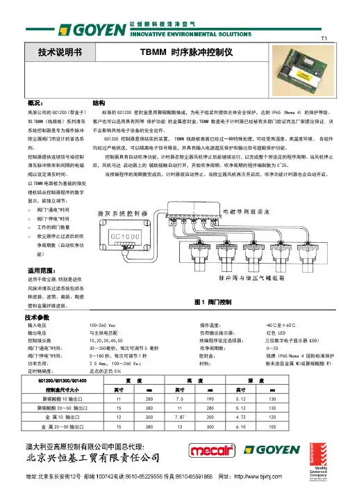
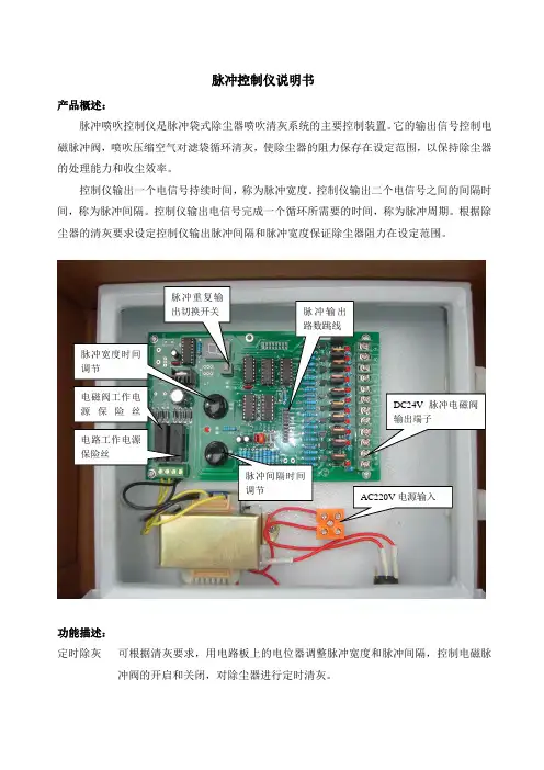
脉冲喷吹控制仪是脉冲袋式除尘器喷吹清灰系统的主要控制装置。
它的输出信号控制电磁脉冲阀,喷吹压缩空气对滤袋循环清灰,使除尘器的阻力保存在设定范围,以保持除尘器的处理能力和收尘效率。
控制仪输出一个电信号持续时间,称为脉冲宽度。
控制仪输出二个电信号之间的间隔时间,称为脉冲间隔。
控制仪输出电信号完成一个循环所需要的时间,称为脉冲周期。
根据除尘器的清灰要求设定控制仪输出脉冲间隔和脉冲宽度保证除尘器阻力在设定范围。
功能描述:
定时除灰可根据清灰要求,用电路板上的电位器调整脉冲宽度和脉冲间隔,控制电磁脉
冲阀的开启和关闭,对除尘器进行定时清灰。
控制通道数量设定控制仪的脉冲输出数量可以通过电路板上的跳线自由选择,它适用于具有不同规格的脉冲袋式除尘器的企业选配统一的控制仪。
安装和接线:
本脉冲控制仪采用螺栓壁挂式固定,尺寸如上。
公共端公
共
端
012345789
6
1.按照图示接好线,并检查有无搭壳,短路等现象。
2.接通电源,开启柜壁上的电源开关。
3.调整脉冲宽度旋钮至脉冲宽度合适,顺时针增大,逆时针减小。
4.调整脉冲间隔旋钮至脉冲间隔合适,顺时针增大,逆时针减小。
5.调整完毕,盖好机壳。
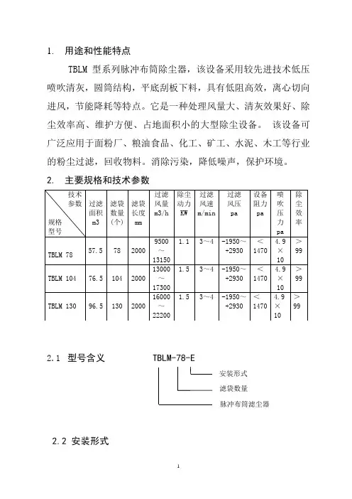
1. 用途和性能特点TBLM 型系列脉冲布筒除尘器,该设备采用较先进技术低压喷吹清灰,圆筒结构,平底刮板下料,具有低阻高效,离心切向进风,节能降耗等特点。
它是一种处理风量大、清灰效果好、除尘效率高、维护方便、占地面积小的大型除尘设备。
该设备可广泛应用于面粉厂、粮油食品、化工、矿工、水泥、木工等行业的粉尘过滤,回收物料。
消除污染,降低噪声,保护环境。
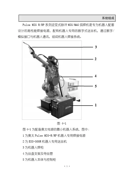
2. 主要规格和技术参数2.1 型号含义 TBLM-78-E2.2 安装形式安装形式 滤袋数量 脉冲布筒滤尘器3.主要结构和工作原理3.1主要结构3.2外形尺寸见下表系列脉冲布筒除尘器主要有上箱体(出口、分配气箱)、中箱体(进气口、中节)、底座(清灰斗)、滤袋、喷吹装置等部分组成。
详见结构图。
3.3工作原理含尘气体从中箱体进风口送入,在气体导流装置的导流下,大颗粒的粉尘被分离,直接落入灰斗。
而较细小的粉尘均匀地进入中箱体而吸附在滤袋的外表面上,洁净气体进入上箱体的各分配器阀,通过排气管排入大气。
随着过滤工况的进行,滤袋上的粉尘越积越多,当设备阻力达到限定值时,有脉冲控制器按差压设定值或清灰时间设定自动关闭,按设定程序打开电控脉部,进行喷吹,利用压缩空气间使滤袋内压力聚增,将滤袋上的粉尘进行抖落至灰斗中,由排灰机构排出。
4.调运安装和调试4.1设备需在运输过程中,不得长期漏天放置,以免锈蚀变形,影响使用寿命。
用户在吊运设备时,钢丝绳索不得与设备的油漆表面及把手接触,接触处应垫上麻袋等软物,避免损伤油漆和机件。
4.2 设备安装前应对基础校队,合格后才能进行安装。
一般由下至上,先把下部的支腿,灰斗安装妥当,再吊装中箱体、上箱体,然后安装气包、配管及电器信号系统。
以确保安装质量。
4.3 安装压缩空气管路时,管道内除去污物防止管道堵塞,安装后清洗管道再进行试压,将压力调至规定值。
4.4 对传动机构要进行专门检查,传动前要向减速机箱内注入润滑油,使机件正常工作。
目录一、用途和特点二、构和工作原理三、型号规格和技术参数四、安装、试车与运转五、设备选型说明六、维护和保养七、用户须知八、附表九、附图一、用途和特点TBLM系列低压脉冲布袋滤尘器是我公司同原国内贸易部科学研究院共同开发研制并经过多年来的实践,在技术上不断提高、更新和完善的新一代产品,许多用户使用该产品后,都收到了较理想的效果。
该设备可广泛用于温度低于80摄氏度的含尘气体的气、尘分离作业,由于脉冲清灰气源是无油、无水,不会污染的气尘,故特别适用于食品、粮食、医药、卫生等行业;也可用于冶金、水泥、矿山、铸造等行业。
主要特点:1、圆筒形箱体,箱体刚度、强度好;含尘气体切向离心入机,起到初级降尘净化功能,提高了除尘效果。
2、气源配套:单台滤尘器可配套滑片或低压气泵;多台设备,可配套低压风泵亦可配套三叶罗茨鼓风机集中供气。
3、清灰脉冲气源压力低,本系列设备特有的低压0.05(0.5kg/cm2)喷吹技术使脉冲阀使用寿命大大延长。
4、占地面积小、噪音低、设备设计紧凑、低压风泵噪音为78dB,低于空压机噪音,气泵配用电机功率低。
5、处理风量大,本系列设备配备了清灰系统,能处理较大的风量。
6、由电子信号直接启动低压冲电磁阀实现喷吹,能处理较大的风量。
7、脉冲控制采用DMK-I型电脑脉冲控制器,该控制器采用进口微电脑芯片,以软件代替硬件,并同时具有WATCHDOG系统,容错设计、抗干扰设计和功能设计三位一体的软件支持,外围电路简单,具有智能化,实现了喷吹间隔,脉宽输入数字化,输出监控化,稳定性能更好,可靠性更高。
8、安装、调试、维修简单。
二、除尘器结构和工作原理1、结构本滤尘器分高上箱体、中箱体、下箱体和支腿等四部分。
上箱体内置电磁阀、气包、喷吹管、花板等零部件,周围置净气出口;中箱体内置滤袋,滤袋固定架,弹簧笼骨等零部件,切向置含尘气体入口,周向上置中检修门;下箱体内置刮灰板,下置刮板减速电机和关风器电机,周向设灰斗检修门。
TBLM系列脉冲布筒除尘器TBLM系列脉冲布筒除尘器是我公司在消化吸收国内外先进技术的基础上,研制开发的新产品。
该设备不但性能稳定、质量可靠,而且能充分利用脉冲除尘器的高效净化回收能力。
现已向社会成功推出,并收到良好的社会效益和经济效益。
该设备主要用于含尘气体的气、尘分离。
一、工作原理含尘气体经进风口切向进入箱体中,部分较粗颗粒粉尘首先离心分离沿筒壁旋转落入箱体,其余粉尘随气流流向滤袋,空气穿过滤袋进入袋内,并进而通过上箱体,从出风口排出,较细的粉尘被滞留在袋内,不能随气流排出,达到了气、尘分离的效果。
随着时间的增长,滤袋外表面的积尘逐渐增多,使气流穿过滤袋的阻力也增加,为使设备维持在限定范围内应定时对布袋清灰达到降低阻力之目的,该系列产品是采用脉冲喷吹系统按一定程序依次对每个滤袋进行清灰,将压缩空气脉冲喷入滤袋,使滤袋迅速膨胀,纤维组织中产生一短暂的反向气流(与过滤气体流向相反)从而清掉滤袋外面的积灰。
二、使用前的准备1、接进风口管路和压缩空气管路注意密封良好。
2、选择方便操作的有利位置,将电子控制器装在滤尘器上。
3、通电检查关风器、气泵转向是否正确,然后关闭电路。
4、接通电子控制器电源,检查步进电机,电磁阀动作是否正确,脉冲的间隔时间,调整正确。
5、空车试运转,观察压力表压力是否正常,喷吹是否正常,气泵、关风器运转是否平稳。
三、使用规则1、启动顺序:关风器——层叠气泵和电子控制箱——风网风机。
停机时顺序相反。
2、脉冲喷吹时间和周期的调整。
脉冲喷吹的调整原则是:观察喷吹气包压力,在每次喷吹后压力回升至最高压力1~2秒后,开始下一个脉冲喷吹。
四、设备的维护及保养1、保持电子控制器表面清洁,有灰尘及时清除。
2、每周打开一次中箱体检查门,检查各滤袋有无破损现象。
3、每半年检查一次脉冲阀中的膜片,发现破损,老化应及时更换。
4、检查下箱体清灰机构是否运转正常,排灰是否顺畅。
定期检查减速机运转部位,减速机应三个月加一次润滑脂。