Lateral response of pile foundations in liquefiable soils
- 格式:pdf
- 大小:6.96 MB
- 文档页数:8

M-Method Calculation of Pile Foundation ExampleBackground:The M-method is a commonly used analytical approach for estimating the capacity of pile foundations. It considers both the axial and lateral loads acting on the pile, as well as the soil-pile interaction. This method is based on the assumption that the pile-soil interaction can be represented by a spring-dashpot system.Example:Let's consider a pile foundation installed in a soil deposit with known geotechnical properties. The pile has a diameter of 1.5 meters and a length of 20 meters. The axial load acting on the pile is 1000 kN, and the lateral load is 200 kN at a depth of 5 meters.Calculation Steps:Soil Properties:Determine the soil's modulus of elasticity (E) and shear modulus (G).Determine the soil's cohesion (c) and friction angle (φ).Pile Properties:Determine the pile's cross-sectional area (A) and moment of inertia (I).Determine the pile's modulus of elasticity (Ep).Spring-Dashpot Model:Calculate the axial stiffness (Kz) and lateral stiffness (Ky) of the pile-soil system using the M-method formulas.Determine the damping coefficients (Cz and Cy) if required for dynamic analysis.Load-Displacement Analysis:Apply the axial and lateral loads to the pile.Solve the governing equations of motion to determine the displacement and internal forces in the pile.Capacity Estimation:Evaluate the pile's ultimate axial and lateral capacities based on the displacement and internal force results.Compare the estimated capacities with the applied loads to assess the pile's safety.Conclusion:Using the M-method, we can estimate the axial and lateral capacities of pile foundations. This method provides a practical and efficient way to analyze pile-soil interaction and assess the pile's performance under various loading conditions.背景:M法是一种常用于估算桩基承载力的分析方法。

文章编号(黑体加粗):1000-7598-(2003) 02―0304―03(编号用Times New Roman)空2行(单倍行距)页面设置:页边距上:2cm(首页)、2.5cm(奇偶页), 下:1.6cm, 左: 2cm, 右: 2cm; 距边界: 页眉: 1.5cm, 页脚: 1.6cm 文档网格: 每行46个字, 每页49行论文标题(不超过20字):二号黑体加粗,居中作者:四号楷体加粗,居中(单位、地址、邮编,6号宋体,居中)摘要(小5宋加粗):控制在200~300字,能使人脱离您的文章独立理解,摘要中不要出现“本文”的字样,也不要有引文号。
(小5宋, 行距14磅)关键词(小5宋加粗):内容:小5宋中图分类号:TU 443(Times New Roman)文献标识码:A空2行(固定值:12磅)Tiltle in English(四号Times New Roman加粗)Author( Address,Postalcode )Abstract(小5加粗):,英文摘要和题名要准确规范,作者拼音和作者单位英译名要规范统一。
(小5, 行距14磅)Key words(同上): soil(同上)。
文中所有英文字体均用Times New Roman空1行,行距:单倍行距1 一级标题4号宋体,顶格左排作者需按排版格式与论文书写要求对自已的论文进行修改、排版,并将排版后的论文全文通过高质量软盘或E-mail 发送至组委会,同时寄全文的激光打印稿2份,以便校核论文。
正文部分分两栏(等宽, 每栏22个字,栏间距2个字, 行距:16磅, 一级标题段前段后空行, 行距16磅。
其中文字为正体,变量、矢量字体倾斜,包括公式、图表)二级标题(5号宋加粗,左齐)正文1.1.1 三级标题(5号宋,左齐)(1)公式要求公式编辑器中需定义的主要参数依次为:, 6, 。
公式编号右齐,单倍行距,公式变量用斜体,矢量、张量为斜体加黑;三角函数、双曲函数、对数、特殊函数的符号、圆周率π、自然对数底e 、虚数单位i 、j 、微分符号d 等均排正体。
基于莫尔-库仑本构模型的桩后土拱效应研究摘要:大量工程实践表明桩后土体的土拱效应是分离布置桩中最重要的力学现象。
认识桩后土体的土拱效应,对于认识桩后土体的应力传递规律、桩周土体的塑性区发展趋势,分析桩土相互作用机理,获得不同土体中抗滑桩的荷载-位移曲线和桩的极限承载力都具有重要工程意义。
为此本文土体采用M-C本构模型,抗滑桩采用线弹性模型, 结合平面应变有限元分析模型研究桩后土拱的发育规律,为实际工程设计提供依据。
关键词:桩后土体;土拱效应; M-C本构模型;平面应变有限元分析;发育规律1 引言岩土工程中经常遇到土拱这一受力现象,土拱效应主要是由于岩土材料的不均匀变形引起的。
土体的不均匀变形造成了土体中应力分布的局部集中,土拱的形成改变了岩土材料中的应力状态,引起了应力重分布,把作用于土拱后或土拱上的压力传递到桩身。
从土力学的角度来看,土拱效应实质上反映了土体为了充分发挥自身抗剪强度,“主动”调整内部应力分布的一种现象。
当用土拱理论来考虑桩土相互作用,建立理论或数值模型分析真实土体的变形和受力状态时,选择合适的土体应力应变关系是一个重要方面;同时土体材料的非线性行为与土体的应力状态,以及土拱的几何形状等也有很大的关系。
本文使用摩尔-库仑土体本构模型以PLAXIS有限元软件[1]模拟桩土相互作用以及真实土体的变形和受力状态,探讨桩后土体的应力变形分布规律,以期对土拱理论的发展和完善起到积极作用。
2 计算分析模型基于PLAXIS 2D采用平面应变有限元模型,模拟桩与土体的相互作用。
在平面上采用单位宽度作为有限元模型的分析对象,d为抗滑桩的桩径,s为桩的中心距。
对称边界采用x方向光滑位移约束。
为减少边界效应的影响,桩的前后边界取30d。
根据不同的分析条件,采用不同桩前边界条件。
通过桩前边界自由,来模拟桩前无土或不考虑桩前土体抗力的情况;通过在桩前边界设置弹簧单元来模拟考虑桩前土体抗力的情况;通过在桩后边界上设置y方向的初始位移来模拟滑坡土体的水平移动和由于位移引起的土体在桩中间的绕流;y方向上的位移通过不同的荷载步逐渐的增加,用来模拟不同桩土相对位移条件下,桩后土拱的发展情况。

第 卷第 期 (小5号宋体) 地球科学——中国地质大学学报 V ol. No. 2003年 月 Earth Science —Journal of China University of Geosciences (月份英文缩写) . 2003基金项目,请在脚注中注明基金及其批准号作者简介:姓名,性别,出生年份,职务。
主要从事哪方面的研究。
文章编号(黑体加粗):1000-7598-(2003) 02―0304―03(编号用Times New Roman ) 空2行(单倍行距)页面设置:页边距 上:2cm(首页)、2.5cm(奇偶页), 下:1.6cm, 左: 2cm, 右: 2cm; 距边界: 页眉: 1.5cm, 页脚: 1.6cm 文档网格: 每行46个字, 每页49行论文标题(不超过22字):二号黑体加粗,居中作者:四号楷体加粗,居中( 单位、地址、邮编,6号宋体,居中 )摘 要(小5宋加粗):控制在200~300字,能使人脱离您的文章独立理解,摘要中不要出现“本文”的字样,也不要有引文号。
(小5宋, 行距14磅)关 键 词(小5宋加粗):内容:小5宋中图分类号:TU 443(Times New Roman ) 文献标识码:A 空2行(固定值:12磅)Tiltle in English (四号Times New Roman 加粗)Author( Address,Postalcode )Abstract (小5加粗):,英文摘要和题名要准确规范,作者拼音和作者单位英译名要规范统一。
(小5, 行距14磅) Key words (同上): soil (同上)。
注:文中所有英文字体均用Times New Roman空1行,行距:单倍行距1 一级标题4号宋体,顶格左排作者需按排版格式与论文书写要求对自已的论文进行修改、排版,并将排版后的论文全文通过高质量软盘或E-mail 发送至组委会,同时寄全文的激光打印稿2份,以便校核论文。

土木工程工程地质岩土工程专业术语专业英语专业词汇岩层岩性lithology,人工堆积artificial accumulation,块石碎石土block and rubble,崩坡积avalanche slope accumulation,坡积slope accumulation,碎石土rubble,残坡积residual slope accumulation,坡洪积diluvial slope accumulation,砂卵砾石sand gravel,冰水堆积outwash accumulation,砂岩夹砾岩夹页岩sandstone interbedded with conglomerate and shale,变质砂岩metamorphic sandstone,硅质板岩siliceous slate,千枚状板岩phyllitic slate,变质砾岩metamorphic conglomerate,砂岩夹砾岩sandstone interbedded with conglomerate,地质构造geological structure,剪裂隙scisson,实测、推测平移断层actual measured and speculative strike-slip fault,实测、推测逆断层actual measured and speculative thrust fault,实测、推测正断层actual measured and speculative normal fault,不同纪系地层分界线formation boundary for different system,实测、推测同纪系地层分界线actual measured and speclative formationboundary for the same system ,岩性相变界线lithofacies change boundary,断层破碎带fractured zone of the fault,地貌及物理地质现象surface feature and geophysical phenomenon,阶地前缘(齿数代表阶地级数)front of the terrace(tooth number for terraceclass),勘探及其他exploration and othera semi-infinite elastic solid|半无限弹性体AASHTO= American Association State HighwayOfficials|美国州公路官员协会active earth pressure|主动土压力additional stress|附加应力allowable bearing capacity of foundation soil|地基容许承载力alluvial expansive soil|冲积膨胀土anchored plate retaining wall|锚定板挡土墙anchored sheet pile wall|锚定板板桩墙angle of internal friction|内摩擦角angle of repose|休止角anisotropy|各向异性ANSYS Booleans|布尔运算ANSYS Booleans Intersect|布尔交运算ANSYS Booleans Overlap|布尔搭接运算ANSYS Booleans Partition|布尔分割运算ANSYS Cartesian|笛卡儿坐标ANSYS Cylindrical|柱坐标ANSYS Eigen Buckling|特征值屈伸分析ANSYS Global Cartesian|笛卡儿坐标系ANSYS Global Cylindrical|柱坐标系ANSYS Global Spherical|球坐标系ANSYS Grid|网格ANSYS Harmonic|谐振分析ANSYS Model|模态分析ANSYS Normal|法向向量ANSYS Polar|极坐标ANSYS Spectrum|谱分析ANSYS Spherical|球坐标ANSYS Static|静态分析ANSYS Substructuring|子结构分析ANSYS Tolerance|允许偏差ANSYS Transient|瞬态分析ANSYS Trial|坐标轴ANSYS Working Plane Origin|工作平面原点anti-slide pile|抗滑桩arrangement of piles|桩的布置artificial foundation|人工地基ASCE=American Society of Civil Engineer|美国土木工程师学会associated flow|关联流动Atterberg limits|阿太堡界限Barraon’s consolidation theory|巴隆固结理论bearing capacity|承载力bearing capacity of foundation soil|地基承载力bearing capacity of single pile|单桩承载力bearing stratum|持力层belled pier foundation|钻孔墩基础bench slope|台阶式坡形Biot’s consolidation theory|比奥固结理论Bishop method|毕肖普法bore hole columnar section|钻孔柱状图bored pile|钻孔桩bottom heave|(基坑)底隆起boulder|漂石boundary surface model|边界面模型box foundation|箱型基础braced cuts|支撑围护braced excavation|支撑开挖braced sheeting|支撑挡板bracing of foundation pit|基坑围护bulk constitutive equation|体积本构模型caisson foundation|沉井(箱)Cambridge model|剑桥模型cantilever retaining wall|悬臂式挡土墙cantilever sheet pile wall|悬臂式板桩墙cap model|盖帽模型casing|套管cast in place|灌注桩cement column|水泥桩cement mixing method|水泥土搅拌桩centrifugal model test|离心模型试验chemical stabilization|化学加固法clay|粘土clay fraction|粘粒粒组clay minerals粘土|矿物clayey silt|粘质粉土clayey soil|粘性土coarse sand|粗砂cobble|卵石coefficent of compressibility|压缩系数coefficient of consolidation|固结系数coefficient of gradation|级配系数coefficient of permeability|渗透系数coefficient of variation|变异系数cohesion|粘聚力collapsible loess treatment|湿陷性黄土地基处理compacted expansive soil|击实膨胀土compaction test|击实试验compactness|密实度compensated foundation|补偿性基础complex texture|复合式结构composite foundation|复合地基compressibility|压缩性compressibility modulus|压缩摸量compression index|压缩指数concentrated load|集中荷载consolidated drained direct shear test|慢剪试验consolidated drained triaxial test|固结排水试验(CD) consolidated quick direct shear test|固结快剪试验consolidated undrained triaxial test|固结不排水试验(CU) consolidation| 固结consolidation curve|固结曲线consolidation test|固结试验consolidation under K0 condition| K0固结constant head permeability|常水头渗透试验constitutive equation|本构关系constitutive model|本构模型Coulomb’s earth pressure theory|库仑土压力理论counter retaining wall|扶壁式挡土墙country rock|围岩critical edge pressure|临塑荷载cross-hole test| 跨孔试验cushion|垫层cyclic loading|周期荷载cycling load|反复荷载damping ratio|阻尼比Darcy’s law| 达西定律dead load sustained load|恒载持续荷载deep foundation|深基础deep settlement measurement|深层沉降观测deep well point|深井点deformation|变形deformation modulus|变形摸量deformation monitoring|变形监测degree of consolidation|固结度degree of saturation|饱和度density|密度dewatering|(基坑)降水dewatering method|降低地下水固结法diaphragm wall|地下连续墙截水墙dilatation|剪胀dimensionless frequency|无量纲频率direct shear|直剪direct shear apparatus|直剪仪direct shear test|直剪试验direct simple shear test|直接单剪试验direction arrangement|定向排列discount coefficient|折减系数diving casting cast-in-place pile|沉管灌注桩domain effect theory|叠片体作用理论drilled-pier foundation|钻孔扩底墩dry unit weight|干重度dry weight density|干重度Duncan-Chang model|邓肯-张模型duration of earthquake|地震持续时间dyke堤|(防)dynamic compaction|强夯法dynamic compaction replacement|强夯置换法dynamic load test of pile|桩动荷载试验dynamic magnification factor|动力放大因素dynamic penetration test|(DPT)动力触探试验dynamic pile testing|桩基动测技术dynamic properties of soils| 土的动力性质dynamic settlement|振陷(动沉降)dynamic shear modulus of soils|动剪切模量dynamic strength|动力强度dynamic strength of soils|动强度dynamic subgrade reaction method|动基床反力法dynamic triaxial test|三轴试验earth pressure|土压力earth pressure at rest|静止土压力earthquake engineering|地震工程earthquake intensity|地震烈度earthquake magnitude|震级earthquake response spectrum|地震反应谱effective stress|有效应力effective stress approach of shear strength|剪胀抗剪强度有效应力法effective stress failure envelop|有效应力破坏包线effective stress strength parameter|有效应力强度参数effective unit weight|有效重度efficiency factor of pile groups|群桩效率系数(η)efficiency of pile groups|群桩效应elastic half-space foundation model|弹性半空间地基模型elastic half-space theory of foundationvibration|基础振动弹性半空间理论elastic model|弹性模型elastic modulus|弹性模量elastoplastic model|弹塑性模型embedded depth of foundation|基础埋置深度end-bearing pile|端承桩engineering geologic investigation|工程地质勘察equivalent lumped parameter method|等效集总参数法equivalent node load|等小结点荷载evaluation of liquefaction|液化势评价ewatering method|降低地下水位法excavation|开挖(挖方)excess pore water pressure|超孔压力expansive ground treatment|膨胀土地基处理expansive soil|膨胀土failure criterion|破坏准则failure of foundation|基坑失稳falling head permeability|变水头试验fatigue test|疲劳试验Fellenius method of slices|费纽伦斯条分法field permeability test|现场渗透试验field vane shear strength|十字板抗剪强度filling condition|填筑条件final set|最后贯入度final settlement|最终沉降fine sand|细砂finite element method|有限员法flexible foundation|柔性基础floor heave|底膨flow net|流网flowing soil|流土foundation design|基础设计foundation engineering|基础工程foundation vibration|基础振动foundation wall|基础墙fractal structure|分形结构free swell|自由膨胀率freezing and heating|冷热处理法free(resonance)vibration column test|自(共)振柱试验friction pile|摩擦桩frozen heave|冻胀frozen soil|冻土general shear failure|整体剪切破化geofabric|土工织物geologic mode|地质结构模式geometric damping|几何阻尼geostatic stress|自重应力geotechnical engineering|岩土工程geotechnical model test|土工模型试验gravel|砂石gravelly sand|砾砂gravity retaining wall|重力式挡土墙ground treatment|地基处理ground treatment in mountain area|山区地基处理groundwater|地下水groundwater level|地下水位groundwater table|地下水位group action|群桩作用high pressure consolidation test|高压固结试验high-rise pile cap|高桩承台homogeneous|均质hydraulic gradient|水力梯度hydrometer analysis|比重计分析hyperbolic model|双曲线模型hysteresis failure|滞后破坏ideal elastoplastic model|理想弹塑性模型in situ test|原位测试in-situ pore water pressure measurement|原位孔隙水压量测in-situ soil test|原位试验initial liquefaction|初始液化initial pressure|初始压力initial stress field|初始应力场isotropic|各向同性ISSMGE=International Society for Soil Mechanics and Geotechnical Engineering|国际土力学与岩土工程学会jet grouting|高压喷射注浆法Kaolinite|高岭石laminar texture|层流结构landslide precasting|滑坡预报landslides|滑坡lateral load test of pile|单桩横向载荷试验lateral pile load test|单桩横向载荷试验lateral pressure coefficient|侧压力系数layered filling|分层填筑leakage|渗流light sounding|轻便触探试验lime soil pile|灰土挤密桩lime-soil compacted column|灰土挤密桩lime-soil compaction pile| 灰土挤密桩limit equilibrium method|极限平衡法limiting pressure|极限压力lining|衬砌liquefaction strength|抗液化强度live load|活载local shear failure|局部剪切破坏long term strength|长期强度long-term strength|长期强度long-term transient load|长期荷载low pile cap|低桩承台material damping|材料阻尼mathematical method|数学模型maximum acceleration of earthquake|地震最大加速度maximum dry density|最大干密度medium sand|中砂modulus of compressibility|压缩模量Mohr-Coulomb failure condition|摩尔-库仑破坏条件Mohr-Coulomb theory|莫尔-库仑理论Mohr-Coulomb yield criterion|莫尔-库仑屈服准则moist unit weight|湿重度multi-dimensional consolidation|多维固结NATM|新奥法natural frequency of foundation|基础自振频率natural period of soil site|地基固有周期net foundation pressure|基底附加应力nonlinear analysis|非线性分析nonlinear elastic model|非线性弹性模型normal distribution| 正态分布normal stresses|正应力normally consolidated soil|正常固结土numerical geotechanics|数值岩土力学one-dimensional consolidation|一维固结optimum water content|最优含水率over consolidation ration| (OCR)超固结比overconsolidated soil|超固结土overconsolidation|超固结性overconsolidation soil|超固结土passive earth pressure|被动土压力peak strength|峰值强度peat|泥炭permeability|渗透性physical properties|物理性质pile caps|承台(桩帽)pile cushion|桩垫pile foundation|桩基础pile groups|群桩pile headt|桩头pile integrity test|桩的完整性试验pile noise|打桩噪音pile pulling test|拔桩试验pile rig|打桩机pile shoe|桩靴pile tip|桩端(头)piles set into rock|嵌岩灌注桩pillow|褥垫piping|管涌plastic drain|塑料排水带plate loading test|载荷试验Poisson ratio|泊松比poorly-graded soil|级配不良土pore pressure|孔隙压力pore water pressure|孔隙水压力pore-pressure distribution|孔压分布precast concrete pile|预制混凝土桩preconsolidated pressure|先期固结压力preconsolidation pressure|先期固结压力preloading|预压法pressuremeter test|旁压试验prestressed concrete pile|预应力混凝土桩prestressed concrete pipe pile|预应力混凝土管桩primary consolidation|主固结primary structural surface|原生结构面principal plane|主平面principal stress|主应力principle of effective stress|有效应力原理probabilistic method|概率法probability of failure|破坏概率progressive failure|渐进破坏punching shear failure|冲剪破坏quick direct shear test|快剪试验rammed bulb pile|夯扩桩rammed-cement-soil pile|夯实水泥土桩法random arrangement|随机排列Rankine’s earth pressure theory|朗金土压力理论rebound index|回弹指数recompaction|再压缩reduced load|折算荷载reinforced concrete sheet pile|钢筋混凝土板桩reinforcement method|加筋法reloading|再加载replacement ratio|(复合地基)置换率residual diluvial expansive soil|残坡积膨胀土residual soil|残积土residual strength|残余强度resistance to side friction|侧壁摩擦阻力retaining wall|挡土墙rigid foundation|刚性基础rigid plastic model|刚塑性模型rolling compaction|碾压root pile|树根桩safety factor|安全系数safety factor of slope|边坡稳定安全系数sand boiling|砂沸sand drain|砂井sand wick|袋装砂井sand-gravel pile|砂石桩sandy silt|砂质粉土saturated soil|饱和土saturated unit weight|饱和重度saturation degree|饱和度screw plate test|螺旋板载荷试验secondary consolidation|次固结secondary minerals|次生矿物secondary structural surface|次生结构面seepage|渗透(流)seepage force|渗透力seepage pressure|渗透压力seismic predominant period|地震卓越周期sensitivity|灵敏度settlement|沉降shaft|竖井身shallow foundation|浅基础shear modulus|剪切摸量shear strain rate|剪切应变速率shear strength|抗剪强度shear strength of interlayered weak surface|层间软弱面强度shear strength of repeated swelling shrinkage|反复胀缩强度shear stresses|剪应力sheet pile structure|板桩结构物shield tunnelling method|盾构法shinkrage coefficient|收缩系数shinkrage limit|缩限short –term transient load|短期瞬时荷载sieve analysis|筛分silent piling|静力压桩silt|粉土silty clay|粉质粘土silty sand|粉土size effect|尺寸效应slaking characteristic|崩解性slices method|条分法slip line|滑动线slope protection|护坡slope stability analysis|土坡稳定分析soft clay|软粘土soft clay ground|软土地基soft soil|软土soil dynamics|土动力学soil fraction|粒组soil mass|土体soil mechanics|土力学special-shaped cast-in-place pile|机控异型灌注桩specific surface|比表面积spread footing|扩展基础square spread footing|方形独立基础sshaft resistance|桩侧阻stability analysis|稳定性分析stability of foundation soil|地基稳定性stability of retaining wall|挡土墙稳定性state of limit equilibrium|极限平衡状态static cone penetration|(SPT) 静力触探试验static load test of pile|单桩竖向静荷载试验steel pile|钢桩steel piles|钢桩steel pipe pile|钢管桩steel sheet pile|钢板桩stress path|应力路径stress wave in soils|土中应力波striation|擦痕strip footing|条基strip foundation|条形基础structural characteristic|结构特征structure-foundation-soil interactionanalysis|上部结构-基础-地基共同作用分析subgrade|路基surcharge preloading|超载预压法surface compaction|表层压实法Swedish circle method|瑞典圆弧滑动法swelling index|回弹指数system of engineering structure|工程结构系统technical code for ground treatment of building|建筑地基处理技术规范tectonic structural surface|构造结构面Terzzaghi’s consolidation theory|太沙基固结理论thermal differential analysis|差热分析three phase diagram|三相图timber piles|木桩time effcet|时间效应time effect|时间效应time factor Tv|时间因子tip resistance|桩端阻total stress|总应力total stress approach of shear strength|抗剪强度总应力法tri-phase soil|三相土triaxial test|三轴试验ultimate bearing capacity of foundation soil|地基极限承载力ultimate lateral resistance of single pile|单桩横向极限承载力unconfined compression|无侧限抗压强度unconfined compression strength|无侧限抗压强度unconsolidated-undrained triaxial test|不固结不排水试验(UU) underconsolidated soil|欠固结土undrained shear strength|不排水抗剪强度Unified soil classification system|土的统一分类系统uniformity coefficient|不均匀系数unloading|卸载unsaturated soil|非饱和土uplift pile|抗拔桩vacuum preloading|真空预压法vacuum well point|真空井点vane strength|十字板抗剪强度vertical allowable load capacity|单桩竖向容许承载力vertical ultimate uplift resistance of single pile|单桩抗拔极限承载力vibration isolation|隔振vibroflotation method|振冲法viscoelastic foundation|粘弹性地基viscoelastic model|粘弹性模型viscous damping|粘滞阻尼water affinity|亲水性wave equation analysi|s波动方程分析wave velocity method|波速法well point system|井点系统(轻型)well-graded soil|级配良好土Winkler foundation model|文克尔地基模型wooden sheet pile|木板桩work hardening|加工硬化work softening|加工软化yield function|屈服函数zonal soil|区域性土一. 综合类geotechnical engineering岩土工程foundation engineering基础工程soil, earth土soil mechanics土力学cyclic loading周期荷载unloading卸载reloading再加载viscoelastic foundation粘弹性地基viscous damping粘滞阻尼shear modulus剪切模量5.soil dynamics土动力学6.stress path应力路径7.numerical geotechanics 数值岩土力学二. 土的分类1.residual soil残积土groundwater level地下水位2.groundwater 地下水groundwater table地下水位3.clay minerals粘土矿物4.secondary minerals次生矿物ndslides滑坡6.bore hole columnar section钻孔柱状图7.engineering geologic investigation工程地质勘察8.boulder漂石9.cobble卵石10.gravel砂石11.gravelly sand砾砂12.coarse sand粗砂13.medium sand中砂14.fine sand细砂15.silty sand粉土16.clayey soil粘性土17.clay粘土18.silty clay粉质粘土19.silt粉土20.sandy silt砂质粉土21.clayey silt粘质粉土22.saturated soil饱和土23.unsaturated soil非饱和土24.fill (soil)填土25.overconsolidated soil超固结土26.normally consolidated soil正常固结土27.underconsolidated soil欠固结土29.soft clay软粘土30.expansive (swelling) soil膨胀土31.peat泥炭32.loess黄土33.frozen soil冻土三. 土的基本物理力学性质 compression index2.cu undrained shear strength3.cu/p0 ratio of undrained strength cu to effective overburden stress p0 (cu/p0)NC ,(cu/p0)oc subscripts NC and OC designated normally consolidated and overconsolidated, respectively4.cvane cohesive strength from vane test5.e0 natural void ratio6.Ip plasticity index7.K0 coefficient of “at-rest ”pressure ,for totalstressesσ1 andσ28.K0‟ domain for effective stressesσ1 … andσ2‟9.K0n K0 for normally consolidated state 10.K0u K0 coefficient under rapid continuous loading ,simulating instantaneous loading or an undrained condition 11.K0d K0 coefficient under cyclic loading(frequency less than 1Hz),asa pseudo- dynamic test for K0 coefficient12.kh ,kv permeability in horizontal and vertical directions, respectively13.N blow count, standard penetration test14.OCR over-consolidation ratio15.pc preconsolidation pressure ,from oedemeter test16.p0 effective overburden pressure 17.p s specific cone penetration resistance, from static cone test 18.qu unconfined compressive strength19.U, Um degree of consolidation ,subscript m denotes mean value of a specimen20.u ,ub ,um pore (water) pressure, subscripts b and m denote bottom of specimen and mean value, respectively21.w0 wL wp natural water content, liquid and plastic limits, respectively22.σ1,σ2 principal stresses, σ1 … andσ2‟ denote effective principal stresses23.Atterberg limits阿太堡界限24.degree of saturation饱和度25.dry unit weight干重度26.moist unit weight湿重度27.saturated unit weight饱和重度28.effective unit weight有效重度29.density密度pactness密实度31.maximum dry density最大干密度32.optimum water content最优含水量33.three phase diagram三相图34.tri-phase soil三相土35.soil fraction粒组36.sieve analysis筛分37.hydrometer analysis比重计分析38.uniformity coefficient不均匀系数39.coefficient of gradation级配系数40.fine-grained soil(silty and clayey)细粒土41.coarse- grained soil(gravelly and sandy)粗粒土42.Unified soil classification system土的统一分类系统43.ASCE=American Society of Civil Engineer美国土木工程师学会44.AASHTO= American Association State HighwayOfficials美国州公路官员协会45.ISSMGE=International Society for Soil Mechanics and Geotechnical Engineering国际土力学与岩土工程学会四. 渗透性和渗流1.Darcy’s law 达西定律2.piping管涌3.flowing soil流土4.sand boiling砂沸5.flow net流网6.seepage渗透(流)7.leakage渗流8.seepage pressure渗透压力9.permeability渗透性10.seepage force渗透力11.hydraulic gradient水力梯度12.coefficient of permeability渗透系数五. 地基应力和变形1.soft soil软土2.(negative) skin friction of drivenpile打入桩(负)摩阻力3.effective stress有效应力4.total stress总应力5.field vane shear strength十字板抗剪强度6.low activity低活性7.sensitivity灵敏度8.triaxial test三轴试验9.foundation design基础设计10.recompaction再压缩11.bearing capacity承载力12.soil mass土体13.contact stress (pressure)接触应力(压力)14.concentrated load集中荷载15.a semi-infinite elastic solid半无限弹性体16.homogeneous均质17.isotropic各向同性18.strip footing条基19.square spread footing方形独立基础20.underlying soil (stratum ,strata)下卧层(土)21.dead load =sustained load恒载持续荷载22.live load活载23.short –term transient load短期瞬时荷载24.long-term transient load长期荷载25.reduced load折算荷载26.settlement沉降27.deformation变形28.casing套管29.dike=dyke堤(防)30.clay fraction粘粒粒组31.physical properties物理性质32.subgrade路基33.well-graded soil级配良好土34.poorly-graded soil级配不良土35.normal stresses正应力36.shear stresses剪应力37.principal plane主平面38.major (intermediate, minor) principal stress最大(中、最小)主应力39.Mohr-Coulomb failure condition摩尔-库仑破坏条件40.FEM=finite element method有限元法41.limit equilibrium method极限平衡法42.pore water pressure孔隙水压力43.preconsolidation pressure先期固结压力44.modulus of compressibility压缩模量45.coefficent of compressibility压缩系数pression index压缩指数47.swelling index回弹指数48.geostatic stress自重应力49.additional stress附加应力50.total stress总应力51.final settlement最终沉降52.slip line滑动线六. 基坑开挖与降水1 excavation开挖(挖方)2 dewatering(基坑)降水3 failure of foundation基坑失稳4 bracing of foundation pit基坑围护5 bottom heave=basal heave (基坑)底隆起6 retaining wall挡土墙7 pore-pressure distribution孔压分布8 dewatering method降低地下水位法9 well point system井点系统(轻型)10 deep well point深井点11 vacuum well point真空井点12 braced cuts支撑围护13 braced excavation支撑开挖14 braced sheeting支撑挡板七. 深基础--deep foundation1.pile foundation桩基础1)cast –in-place灌注桩diving casting cast-in-place pile沉管灌注桩bored pile钻孔桩special-shaped cast-in-place pile机控异型灌注桩piles set into rock嵌岩灌注桩rammed bulb pile夯扩桩2)belled pier foundation钻孔墩基础drilled-pier foundation钻孔扩底墩under-reamed bored pier 3)precast concrete pile预制混凝土桩4)steel pile钢桩steel pipe pile钢管桩steel sheet pile钢板桩5)prestressed concrete pile预应力混凝土桩prestressed concrete pipe pile预应力混凝土管桩2.caisson foundation沉井(箱)3.diaphragm wall地下连续墙截水墙4.friction pile摩擦桩5.end-bearing pile端承桩6.shaft竖井;桩身7.wave equation analysis波动方程分析8.pile caps承台(桩帽)9.bearing capacity of single pile单桩承载力teral pile loadtest单桩横向载荷试验11.ultimate lateral resistance of single pile单桩横向极限承载力12.static load test of pile单桩竖向静荷载试验13.vertical allowable load capacity单桩竖向容许承载力14.low pile cap低桩承台15.high-rise pile cap高桩承台16.vertical ultimate uplift resistance of singlepile单桩抗拔极限承载力17.silent piling静力压桩18.uplift pile抗拔桩19.anti-slide pile抗滑桩20.pile groups群桩21.efficiency factor of pile groups群桩效率系数(η)22.efficiency of pile groups群桩效应23.dynamic pile testing桩基动测技术24.final set最后贯入度25.dynamic load test of pile桩动荷载试验26.pile integrity test桩的完整性试验27.pile head=butt桩头28.pile tip=pile point=pile toe桩端(头)29.pile spacing桩距30.pile plan桩位布置图31.arrangement of piles =pile layout桩的布置32.group action群桩作用33.end bearing=tip resistance桩端阻34.skin(side) friction=shaft resistance桩侧阻35.pile cushion桩垫36.pile driving(by vibration) (振动)打桩37.pile pulling test拔桩试验38.pile shoe桩靴39.pile noise打桩噪音40.pile rig打桩机八. 地基处理--ground treatment1.technical code for ground treatment of building建筑地基处理技术规范2.cushion垫层法3.preloading预压法4.dynamic compaction强夯法5.dynamic compaction replacement强夯置换法6.vibroflotation method振冲法7.sand-gravel pile砂石桩8.gravel pile(stone column)碎石桩9.cement-flyash-gravel pile(CFG)水泥粉煤灰碎石桩10.cement mixing method水泥土搅拌桩11.cement column水泥桩12.lime pile (lime column)石灰桩13.jet grouting高压喷射注浆法14.rammed-cement-soil pile夯实水泥土桩法15.lime-soil compaction pile 灰土挤密桩lime-soil compacted column灰土挤密桩lime soil pile灰土挤密桩16.chemical stabilization化学加固法17.surface compaction表层压实法18.surcharge preloading超载预压法19.vacuum preloading真空预压法20.sand wick袋装砂井21.geofabric ,geotextile土工织物posite foundation复合地基23.reinforcement method加筋法24.dewatering method降低地下水固结法25.freezing and heating冷热处理法26.expansive ground treatment膨胀土地基处理27.ground treatment in mountain area山区地基处理28.collapsible loess treatment湿陷性黄土地基处理29.artificial foundation人工地基30.natural foundation天然地基31.pillow褥垫32.soft clay ground软土地基33.sand drain砂井34.root pile树根桩35.plastic drain塑料排水带36.replacement ratio(复合地基)置换率九. 固结consolidation1.Terzzaghi’s consolidation theory太沙基固结理论2.Barraon’s consolidation theory巴隆固结理论3.Biot’s consolidation theory比奥固结理论4.over consolidation ration (OCR)超固结比5.overconsolidation soil超固结土6.excess pore water pressure超孔压力7.multi-dimensional consolidation多维固结8.one-dimensional consolidation一维固结9.primary consolidation主固结10.secondary consolidation次固结11.degree of consolidation固结度12.consolidation test固结试验13.consolidation curve固结曲线14.time factor Tv时间因子15.coefficient of consolidation固结系数16.preconsolidation pressure前期固结压力17.principle of effective stress有效应力原理18.consolidation under K0 condition K0固结十. 抗剪强度shear strength1.undrained shear strength不排水抗剪强度2.residual strength残余强度3.long-term strength长期强度4.peak strength峰值强度5.shear strain rate剪切应变速率6.dilatation剪胀7.effective stress approach of shear strength 剪胀抗剪强度有效应力法8.total stress approach of shear strength抗剪强度总应力法9.Mohr-Coulomb theory莫尔-库仑理论10.angle of internal friction内摩擦角11.cohesion粘聚力12.failure criterion破坏准则13.vane strength十字板抗剪强度14.unconfined compression无侧限抗压强度15.effective stress failure envelop有效应力破坏包线16.effective stress strength parameter有效应力强度参数十一. 本构模型--constitutive model1.elastic model弹性模型2.nonlinear elastic model非线性弹性模型3.elastoplastic model弹塑性模型4.viscoelastic model粘弹性模型5.boundary surface model边界面模型6.Duncan-Chang model邓肯-张模型7.rigid plastic model刚塑性模型8.cap model盖帽模型9.work softening加工软化10.work hardening加工硬化11.Cambridge model剑桥模型12.ideal elastoplastic model理想弹塑性模型13.Mohr-Coulomb yield criterion莫尔-库仑屈服准则14.yield surface屈服面15.elastic half-space foundation model弹性半空间地基模型16.elastic modulus弹性模量17.Winkler foundation model文克尔地基模型十二. 地基承载力--bearing capacity of foundation soil1.punching shear failure冲剪破坏2.general shear failure整体剪切破化3.local shear failure局部剪切破坏4.state of limit equilibrium极限平衡状态5.critical edge pressure临塑荷载6.stability of foundation soil地基稳定性7.ultimate bearing capacity of foundation soil地基极限承载力8.allowable bearing capacity of foundation soil地基容许承载力十三. 土压力--earth pressure1.active earth pressure主动土压力2.passive earth pressure被动土压力3.earth pressure at rest静止土压力4.Coulomb’s earth pressure theory库仑土压力理论5.Rankine’s earth pressure theory朗金土压力理论十四. 土坡稳定分析--slope stability analysis1.angle of repose休止角2.Bishop method毕肖普法3.safety factor of slope边坡稳定安全系数4.Fellenius method of slices费纽伦斯条分法5.Swedish circle method瑞典圆弧滑动法6.slices method条分法十五. 挡土墙--retaining wall1.stability of retaining wall挡土墙稳定性2.foundation wall基础墙3.counter retaining wall扶壁式挡土墙4.cantilever retaining wall悬臂式挡土墙5.cantilever sheet pile wall悬臂式板桩墙6.gravity retaining wall重力式挡土墙7.anchored plate retaining wall锚定板挡土墙8.anchored sheet pile wall锚定板板桩墙十六. 板桩结构物--sheet pile structure1.steel sheet pile钢板桩2.reinforced concrete sheet pile钢筋混凝土板桩3.steel piles钢桩4.wooden sheet pile木板桩5.timber piles木桩十七. 浅基础--shallow foundation1.box foundation箱型基础2.mat(raft) foundation片筏基础3.strip foundation条形基础4.spread footing扩展基础pensated foundation补偿性基础6.bearing stratum持力层7.rigid foundation刚性基础8.flexible foundation柔性基础9.embedded depth of foundation基础埋置深度 foundation pressure基底附加应力11.structure-foundation-soil interactionanalysis上部结构-基础-地基共同作用分析十八. 土的动力性质--dynamic properties of soils1.dynamic strength of soils动强度2.wave velocity method波速法3.material damping材料阻尼4.geometric damping几何阻尼5.damping ratio阻尼比6.initial liquefaction初始液化7.natural period of soil site地基固有周期8.dynamic shear modulus of soils动剪切模量9.dynamic magnification factor动力放大因素10.liquefaction strength抗液化强度11.dimensionless frequency无量纲频率12.evaluation of liquefaction液化势评价13.stress wave in soils土中应力波14.dynamic settlement振陷(动沉降)十九. 动力机器基础1.equivalent lumped parameter method等效集总参数法2.dynamic subgrade reaction method动基床反力法3.vibration isolation隔振4.foundation vibration基础振动5.elastic half-space theory of foundationvibration基础振动弹性半空间理论6.allowable amplitude of foundation基础振动容许振幅7.natural frequency of foundation基础自振频率二十. 地基基础抗震1.earthquake engineering地震工程2.soil dynamics土动力学3.duration of earthquake地震持续时间4.earthquake response spectrum地震反应谱5.earthquake intensity地震烈度6.earthquake magnitude震级7.seismic predominant period地震卓越周期8.maximum acceleration of earthquake地震最大加速度二十一. 室内土工实验1.high pressure consolidation test高压固结试验2.consolidation under K0 condition K0固结试验3.falling head permeability变水头试验4.constant head permeability常水头渗透试验5.unconsolidated-undrained triaxial test不固结不排水试验(UU)6.consolidated undrained triaxial test固结不排水试验(CU)7.consolidated drained triaxial test固结排水试验(CD)paction test击实试验9.consolidated quick direct shear test固结快剪试验10.quick direct shear test快剪试验11.consolidated drained direct shear test慢剪试验12.sieve analysis筛分析13.geotechnical model test土工模型试验14.centrifugal model test离心模型试验15.direct shear apparatus直剪仪16.direct shear test直剪试验17.direct simple shear test直接单剪试验。
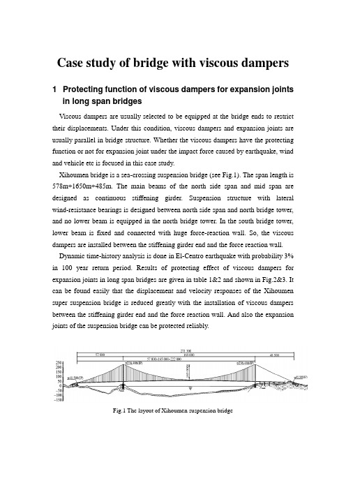
Case study of bridge with viscous dampers1 Protecting function of viscous dampers for expansion jointsin long span bridgesViscous dampers are usually selected to be equipped at the bridge ends to restrict their displacements. Under this condition, viscous dampers and expansion joints are usually parallel in bridge structure. Whether the viscous dampers have the protecting function or not for expansion joint under the impact force caused by earthquake, wind and vehicle etc is focused in this case study.Xihoumen bridge is a sea-crossing suspension bridge (see Fig.1). The span length is 578m+1650m+485m. The main beams of the north side span and mid span are designed as continuous stiffening girder. Suspension structure with lateral wind-resistance bearings is designed between north side span and north bridge tower, and no lower beam is equipped in the north bridge tower. In the south bridge tower, lower beam is fixed and connected with huge force-reaction wall. So, the viscous dampers are installed between the stiffening girder end and the force reaction wall. Dynamic time-history analysis is done in El-Centro earthquake with probability 3% in 100 year return period. Results of protecting effect of viscous dampers for expansion joints in long span bridges are given in table 1&2 and shown in Fig.2&3. It can be found easily that the displacement and velocity responses of the Xihoumen super suspension bridge is reduced greatly with the installation of viscous dampers between the stiffening girder end and the force reaction wall. And also the expansion joints of the suspension bridge can be protected reliably.Fig.1 The layout of Xihoumen suspension bridgeTable 2 Relative velocity aFig.2 Comparison of relative displacements of north beam endFig.3 Comparison of relative velocities of north beam end2 Case study on lateral response reduction of long-spanrailway cable-stayed bridge with viscous dampersThe long-span railway cable-stayed bridge is a semi-floating system with span length of 81m+135m+432m+135m+81m (see Fig.4). The main bridge beam is a steel truss with width of 18m and height of 14m. The length of each truss section is 13.5m. High-strength steel wires are adopted and designed as materials of the 56 pairs of stable cables. The cable spacing distance is 2.5m-4.0m on the main bridge tower and 13.5m on the main bridge beam. The bridge surface is integral orthotropic steel plates. Dynamic responses are conducted by Midas software in three earthquakes with probability 2-3% in 50 year return period. The peak accelerations of the thee earthquakes are all the same of 0.21g. The specific installation places of the viscous damper are shown in Fig.5. Computational results of dynamic transverse relative displacement responses between bridge pier and beam are shown in Fig.6 and the hysteresis curves of viscous dampers between damping force and displacement are shown in Fig.7.It can be found that the earthquake-reduction system is better than other systems by setting up viscous dampers between auxiliary pier, transition pier and bridge beam, for lateral seismic response of main tower, auxiliary pier and transition pier can be significantly reduced. Future more, seismic performance of pile foundations for auxiliary and transition pier can be improved.Fig.4 The long-span railway cable-stayed bridge model (1# is transition bridge pier, 2# is auxiliary bridge pier, 3# is bridge main tower, 4# is bridge main tower, 5# istransition bridge pier, and 6# is bridge abutment)Fig.5 Installation places of viscous dampersFig. 6 Transverse relative displacement between 1#pier and bridge beamFig.7 Hysteresis curves of viscous damper at 2# bridge pier.3 Case study on seismic performance improvement forsouthern branch main bridge of a sea-crossing bridge with viscous dampersThe southern branch main bridge of the sea-crossing bridge in this case study is a semi-floating system with span length of 130m+290m+130m (see Fig.8). The cross-section of the main beam of the southern branch bridge is single-box concrete section with three holes. The height of the cross section is 3.5m and width is 32.2m. The height of the main bridge tower is 132.6m above the bridge pile.This bridge lies in the earthquake-prone areas and the peak acceleration is very big in this area. In this case study, the peak acceleration is 0.311g. In order to improve the dynamic responses of the bridge in design earthquake excitations, viscous dampers are selected and installed under the main bridge beam, namely between the main longitudinal bridge beam and the bridge pier (see Fig.9). Parameter analysis of viscous dampers, such as damping coefficients and damping index, is conducted so as to obtain the optimal damper parameters. The parameters studied in this case study are listed in Table 3.The influence of damper parameters, damping coefficients and damping index, to the energy dissipation ratios of the bridge are shown in Fig.10 & 11,respectively. According to the parameter analysis based on the figures of Fig.10 & 11, the optimal damping parameters can then be easily obtained and given in Table 4.As a result, two vibration control plans are designed. The first one is that 4 viscous dampers are installed between the main bridge beam and the bridge pier of the main tower. And the second is that 4 viscous dampers are installed between the main bridge beam and the bridge pier of the main tower, and 4 dampers are installed between the main bridge beam and the transition bridge pier. However, the total damping coefficients of the two plans are the same for comparison purpose. Comparison of energy dissipation ratio of the bridge with the two control plans are shown in Fig.12. The symbol meanings listed in the Fig. 12 are given in Table 5. Obviously, the analysis indicates that both relative displacement of key points and seismic response of key components could be obviously reduced with reasonably choosing the parameters and locations of dampers.Fg.8 The southern branch main bridge modelFg.9 Installation of the viscous damper under the main bridge beam(a) Influence of C to displacement of beam end (b) Influence of C to displacement of top tower(c) Influence of C to moment of tower bottom (d) Influence of C to moment of top pile Fig.10 Influence of damping coefficients C to the energy dissipation ratio of different parameterresponses(a) Influence of α to displacement of beam end (b) Influence of αto displacement of top tower(c) Influence of αto moment of tower bottom (d) Influence of αto moment of top pileFig. 11 Influence of damping index αto the energy dissipation ratio of different parameterresponsesFig. 12 Comparison of energy dissipation ratio of the bridge with the two control plans4 Case study on performance improvement of stay cable ofJianshao bridge using viscous dampersIn this case study, Jianshao cable-stayed bridge with 69,500m length and 6 main tower is introduced (see Fig.13). The span length is 70m+200m+5×428m+200m +70m. The cables are made up of parallel high-strength steel wires with diameter size of 7mm. Totally, there are 576 stay cables and 432 of these stay cables are installed viscous so as to improve the vibration performance, see Fig.14. The parameters of the viscous dampers are given in Table 6.Site measurement values of the logarithmic decrement ratio of the No. Z5W-B10 cable with and without viscous dampers are given in Table 7. The free decay curves of the No. Z5W-B10 cable using also the site measurement method are shown in Fig.15. And the hysteresis curves of the viscous dampers are shown in Fig.16. The results show that viscous dampers can be able to curb the vibration of stay cables, which can be the permanent vibration control measure for stay cables. And the results of the testing demonstrate that the viscous dampers show stable performance, all the performance index can meet the design requirements. The measured logarithmic decrement is above 6%, basically in compliance with the changing rule of the theoretical values, proving that the viscous dampers have sound vibration damping effect.Fig.13 Jianshao cable-stayed bridge(a) Before installation of viscous dampers (b) After installation of viscous dampersFig.14 Site installation of viscous dampersTable 7 Site measurement values of the logarithmic decrement ratio of the No.(a) Original curves(b) Filtering curve of the 1st order(c) Filtering curve of the 2nd order(d) Filtering curve of the 3rd orderFig.15 Free decay curves of the No. Z5W-B10 cableFig.16 Hysteresis curves of the viscous dampers used in the stay cable of Jiaoshao bridge。
F 部结构substructure桥墩pier 墩身pier body墩帽pier cap, pier cop ing台帽abutme nt cap, abutme nt cop ing盖梁bent cap又称“帽梁”。
重力式[桥]墩gravity pier实体[桥]墩solid pier空心[桥]墩hollow pier柱式[桥]墩column pier, shaft pier单柱式[桥]墩single-columned pier, single shaft pier双柱式[桥]墩two-columned pier, two shaft pier 排架桩墩pile-be nt pier丫形[桥]墩Y-shaped pier柔性墩flexible pier制动墩brak ing pier, abutme nt pier单向推力墩si ngle direct ion thrusted pier抗撞墩an ti-collisi on pier锚墩an chor pier辅助墩auxiliary pier破冰体ice apron防震挡块an ti-k nock block, restra in block桥台abutme nt台身abutme nt body前墙front wall又称“胸墙”。
翼墙wi ng wall又称“耳墙”。
U 形桥台U-abutment八字形桥台flare win g-walled abutme nt一字形桥台head wall abutme ntT 形桥台T-abutme nt箱形桥台box type abutme nt拱形桥台arched abutme nt重力式桥台gravity abutme nt埋置式桥台buried abutme nt扶壁式桥台coun terfort abutme nt, buttressed abutme nt衡重式桥台weight-bala need abutme nt锚碇板式桥台an chored bulkhead abutme nt支撑式桥台supported type abutme nt又称“轻型桥台”。
第 54 卷第 8 期2023 年 8 月中南大学学报(自然科学版)Journal of Central South University (Science and Technology)V ol.54 No.8Aug. 2023考虑两端实际约束的隧道施工诱发邻近桩基响应解析解孙影杰,施成华,王祖贤,张轩煜,郑晓悦(中南大学 土木工程学院,湖南 长沙,410075)摘要:隧道施工不可避免地会对邻近桩基产生影响,对既有桩基响应进行分析时大多将桩顶和桩端假定为自由或固定边界,这与桩基实际约束条件不符。
为反映桩基两端的实际约束状态,并考虑桩基剪切效应,将桩基简化为Vlasov 地基中具有广义弹性约束的Timoshenko 梁,建立隧道−土体−桩基简化计算模型。
基于弹性地基梁理论,采用两阶段法推导邻近隧道施工时任意边界约束条件下桩身横向附加变形和内力的解析解。
通过本文解析解与边界元和有限元数值解进行对比,验证解析模型的可靠性。
最后,给出桩基两端实际约束的简化计算方法,并进一步分析桩顶及桩端约束条件对桩基横向变形和内力的影响规律。
研究结果表明:桩顶转动弹簧刚度K θ0对桩顶横向变形的影响较小;当1×10⁴<K t0<1×10⁶ kN/m 时,桩顶横向变形随桩顶水平弹簧刚度K t0的变化最显著;当K t0<1×10³ kN/m 且K θ0<1×10³ kN·m/rad 时,桩顶近似为自由端;当K t0>1×10⁷ kN/m 且K θ0>1×10⁷ kN·m/rad 时,可按桩顶固定简化计算;当桩端水平弹簧刚度K tn <1×10³ kN/m 时,可按桩端自由简化计算;当K tn >1×10⁸ kN/m 时,可按桩端固定简化计算。
采用本文方法可较准确地预测隧道施工影响下邻近桩基的响应特性,对于现场施工具有重要指导意义。
第30卷第5期 岩 土 力 学 V ol.30 No.5 2009年5月 Rock and Soil Mechanics May 2009收稿日期:2007-12-03基金项目:国家自然科学基金资助项目(No. 50409007);国家863重大资助项目(No. 2006AA09A106)。
第一作者简介:王腾,男,1973年生,博士,教授,主要从事海洋岩土工程方面的研究。
E-mail:*****************文章编号:1000-7598 (2009) 05-1343-04粉土p -y 曲线的试验研究王 腾1,王天霖2(1.中国石油大学(华东)石油工程学院,青岛 255666;2.大连海事大学 机电与材料工程学院,大连 116026)摘 要:进行了浸水黄河粉土中模型钢管桩的水平静力荷载试验,对试验弯矩用6阶多项式进行拟合,推得了黄河粉土的p -y 曲线,并与API 建议砂土和软黏土p-y 曲线进行了比较。
根据粉土试验p-y 曲线,提出了黄河粉土p-y 曲线的理论表达式,用此理论p-y 曲线进行了水平荷载下模型桩的数值分析,并与试验测试弯矩进行了比较。
研究结果表明:粉土的黏聚力对p-y 曲线有很大的影响,忽略粉土黏聚力的抗力作用将导致桩基水平承载力的设计偏于保守;基于理论粉土p-y 的模型桩的数值结果与试验弯矩值吻合得较好。
关 键 词:p-y 曲线;黄河粉土;模型桩;试验研究 中图分类号:TU 411;TU 473 文献标识码:AExperimental research on silt p -y curvesWANG Teng 1, WANG Tian-lin 2(1. School of Petroleum Engineering, China University of Petroleum, Dongying 257061, China; 2. Electromechanical and Materials Engineering College, Dalian Maritime University, Dalian 116026, China)Abstract: An experimental research on a model pile embedded in a deposit of submerged silt has been carried out under lateral static loadings. The 6th order polynomial function was selected to fit the tested results and back-calculate the lateral soil reaction p and lateral deflection y . Thus, the silt p -y curves and theoretical p -y curves formulation accounted for both angle of friction and cohesion component were proposed and compared with the API recommended ones for sand and soft clay, respectively. The results indicate that the cohesion component has great effect on the p-y curves, neglecting the soil resistance from the cohesion component, sometimes will lead to a significant conservation pile foundation design in the case of silt. And the predicted bending moment responses of the model pile using these silt p -y curves are in good agreement with the experiment results. Key words: p-y curves; Yellow River silt; model pile ; experimental research1 引 言对海洋平台桩基通常采用美国石油研究院(American Petroleum Institute )[1]建议的p -y (土反力-桩身位移)曲线法进行设计,但其推荐的p-y 曲线主要是针对砂土和黏土,对粉土p-y 曲线的研究则相对较少。
第十二章桩基础-单桩Chapter12 Pile foundation-single piles301.Piles桩pile cap桩帽piles桩soft clay软粘土sand砂土raker pile斜桩batter pile斜桩302.Vibrations振动tanks贮罐silos筒仓chimneys烟囱machine foundations机器基础sand砂土ground water地下水303.Examples of pile foundations桩基础的例子compaction piles压实桩raked piles斜桩damping of piles桩的阻尼small damping小阻尼vibrations振动304.Stability of bridge abutment桥墩的稳定性soft clay软粘土fill填土bridge abutment桥墩305.Embankment piles路堤桩soft clay软粘土raked piles斜桩bridge abutment桥墩fill填土306.Anchor piles for dry docks,subway stations 干船坞或地铁车站下的锚桩ground water地下水up-lift上浮力anchor piles锚桩307.Offshore structures on piles桩支撑的离岸结构物cyclic loading循环荷载scour冲刺compression压缩steel pipe piles钢管桩tension force拉力308.Stabilisation of slope by piles边坡用桩稳定slope stability边坡稳定性large diameter pile大直径桩steel pipe piles钢管桩failure surface破坏面309.Design of embankment piles路堤桩的设计failure surface破坏面clay粘土precast piles预制桩310.Anchor piles in swelling soil膨胀土中的锚桩seasonal changes季节性变化swelling clay膨胀性粘土montmorillonite蒙脱石high liquid limit高液限high plasticity index高塑性指数building建筑物311.Examples of pile types桩型应用的例子driven piles打入桩bored piles钻孔桩jacked-down piles静压桩screw piles螺旋桩hydraulic jack液压桩312.Piles foundations桩基础concrete pile混凝土桩steel pile钢桩timber木桩H pile H型桩313.Piles types桩型large displacement piles大量挤土桩small displacement piles少量挤土桩non-displacement piles非挤土桩bored piles钻孔桩precast piles预制桩pipe piles管桩cased有套管uncased无套管box piles箱形桩driven cast-in-place piles沉管灌注桩314.Loading conditions of piles桩的荷载情况compression受压lateral load受侧向荷载tension受拉315.Load transfer to piles桩的荷载传递friction or floating piles摩擦桩或悬浮桩end bearing piles端承桩clay粘土sand砂土rock岩石316.Timber piles木桩advantages优点difficulties难点limit bearing capacity极限承载力soft clay软粘土tip桩尖shaft桩身ground water地下水butt桩顶marine borers海生木蛀虫317.Pile splices桩的连接steel sleeve钢套steel strap钢板条318.Splices and rock points桩的连接和入岩桩尖rock point入岩桩尖319.Precast concrete piles预制混凝土桩point桩尖concrete混凝土reinforcement加筋pile diameter桩径shoe桩靴320.Lifting of piles桩的吊装pile length桩长lifting hooks吊钩moment弯矩321.Prestressed concrete piles预应力混凝土桩height strength concrete高强混凝土brittle脆性reduced cracking减少裂缝reduced ductility延展性差322.Concrete strength(CP 2004)混凝土强度(CP 2004)cube strength立方体强度hard driving难以打入normal to easy driving从正常到易于打入high capacity承载力高reduced weight重量减轻easy driving易于打入323.Installation of jacked-down piles静压桩的成桩pump泵manometer压力计steel insert钢垫片hydraulic jack液压千斤顶pile segment桩段324.Bored piles钻孔桩auger螺旋钻reinforcement钢筋笼tremmie pipe导管concreting灌注混凝土325.Examples of bored piles钻孔灌注桩的例子bored piles钻孔桩drilling of shaft桩孔钻进drilling of bell扩大头钻进concrete混凝土stiff clay硬粘土reinforcement钢筋笼326.Bored piles with bell有支盘的钻孔桩bells支盘327.Cast-in-place piles就地灌注桩casing钢管桩driving打(桩)casing filled with water套管充水casing filled with concrete套管中灌注混凝土reinforcement钢筋笼328.Necking during casting of pile shaft in soft clay 软粘土中灌注桩身混凝土时发生缩径casing套管soft clay软粘土sand or silt砂土或粉土ground water地下水329.Slurry trench wall construction泥浆连续墙施工ground water地下水surface casing地下护筒bentonite slurry膨润土泥浆chisel冲抓pouring of concrete灌注混凝土lowering of reinforcement element下放钢筋笼330.Shapes of slurry trench pile elements泥浆护壁类桩型的形状size尺寸331.Raymond step tapered pile雷蒙特锥形桩steel shell钢壳steel core钢芯light bulb小球体reinforcement cage钢筋笼casting of concrete灌注混凝土332.Franki pile弗兰基桩concrete plug混凝土塞bulb球形物internal hammer内夯桩prefabricated[pri:'fæbrikeitid] shaft预制桩身light casing薄壁套管333.Steel H-pipeH-型钢桩easy to drive易于打入easy to cut易于切断corrosion[kə'rəuʒən]腐蚀expensive昂贵splicing分段连接soil plug土塞driving shoe桩靴steel plate钢板wielding焊接334.Steel pipe piles钢管桩diameter直径closed or open ended闭口或开口soil plug土塞diameter直径335.Corrosion腐蚀steel piles钢桩concrete piles混凝土桩National Bureau['bjuərəu] of Standards国家标准局splices连接reinforcement钢筋salt water海水resistivity电阻系数salt water海水encased in concrete做混凝土外壳cathodic[kə'θɔdik] protection阴极保护painting涂刷epoxy[ep'ɔksi]环氧树脂336.Settlement around during driving in sand砂土中沉桩时桩周土发生沉降settlement沉降diameter直径compaction within this zone在此范围内压实337.Effect of pile driving in clay粘土中打桩的影响soft clay软粘土heave隆起volume体积remoulded zone重塑区pore water pressure孔隙水压力undrained shear strength不排水抗剪强度338.Redriving of piles in clay粘性土中桩的复打risen piles上抬的桩redriving复打heave隆起soft clay软粘土separation of splice接桩处脱开339.Load distribution along pile荷载沿桩身的分布sand砂土clay粘土point resistance桩尖阻力shaft resistance桩侧阻力340.Pile load as function of pile displacement桩荷载为桩位移的函数load荷载displacement位移soft clay软粘土stiff clay硬粘土sand砂土cast in place pile就地灌注桩driven pile打入桩with bell有大头341.Load deformation relationship of piles桩的荷载与变形的关系pile load桩荷载displacement位移point resistance端阻力skin resistance表面摩阻力/桩周阻力342.Direction of pile loading桩承受荷载的方向compression受压tension受拉weight of pile桩的自重factor of safety安全系数allowable load容许荷载point resistance端阻力shaft resistance侧阻力343.Determination of bearing capacity at pile point 桩端承载力的确定end bearing端承力undrained shear strength不排水抗剪强度bearing capacity factor承载力系数344.Pile bearing capacity according to Meyerhof 梅耶霍夫对桩的承载力的计算friction angle摩擦角bearing capacity factor承载力系数345.Bearing capacity factor of piles桩的承载力系数Terzaghi太沙基(人名)Berezantsev别列赞采夫(人名)Meyerhof梅耶霍夫(人名)Vesic维西克(人名)Brinch Hansen勃林奇·汉森(人名)Debeer德皮尔(人名)friction angle摩擦角346.Failure mechanism at pile point桩端的破坏机理point resistance端阻力rigidity index刚度指数failure surface破坏面compressibility可压缩性parison of cone resistance and pile point resistance 圆锥贯入阻力与桩端阻力的比较area of pile桩的截面积sand砂土parison of SPT N-value and pile point resistance标准贯入试验N值与桩端阻力的比较SPT标准贯入试验sand砂土pile diameter桩径teral pressure against pile shaft桩身的侧压力bored pile钻孔桩small displacement pile少量挤土桩large displacement pile 大量挤土桩straight shaft直身tapered shaft锥形桩身lateral earth pressure侧土压力350.Determination of capacity in sand砂土中桩承载力的确定loose松散dense密实coefficient of lateral earth pressure at rest静止侧土压力系数small Vesic小维西克(人名)displacement pile挤土桩non-displacement pile非挤土桩tapered pile锥形桩351.Pile shaft capacity in sand砂土中桩身的承载力pile type桩型sand砂土critical depth临界深度teral pressure against pile shaft桩身的侧压力Mansur & Hunter曼舍与洪特(人名)Tavenas泰凡纳斯(人名)lateral earth pressure侧土压力step taper piles多级锥形桩353.Critical depth of pile shaft resistance桩身阻力的临界深度friction angle摩擦角bearing capacity value承载值diameter直径length长度354.Estimate of pile capacity based on Weight Sounding Test(WST)重力触探试验(WST)估算桩的承载力half-turns半转timber piles木桩concrete piles混凝土桩Norwegian Pile Commission挪威桩基委员会skin area表面积355.Failure surface at pile point in clay粘土中桩端的破坏面failure surface破坏面diameter直径area of pile桩的截面356.Skin friction resistance along pile shaft摩阻力沿桩身的分布cone penetration test圆锥贯入试验friction sleeve摩阻套small displacement pile少量挤土桩large displacement pile大量挤土桩357.Bearing capacity of piles in clay粘土中的桩的承载力normally consolidated clay正常固结粘土overconsolidated clay超固结粘土undrained shear strength不排水抗剪强度reduction折减ground surface地表mbda-methodLambda方法offshore structures离岸结构物depth深度mean value平均值skin resistance桩周阻力359.Estimate of pile skin resistance in clay粘土中桩侧阻力的估算effective overburden pressure有效覆盖压力Flaate法莱特(人名)undrained shear strength不排水抗剪强度360.Load transfer from pile to soil as function of pile displacement 桩土间荷载传递为桩位移的函数t-z curves t-z曲线q-y curve q-y曲线driven pile打入桩bored pile钻孔桩361.Negative skin friction along piles桩的负摩阻力lowering of ground water level地下水位下降driven pile打入桩bored pile钻孔桩362.Failure modes of horizontally loaded piles承受水平荷载的桩的破坏模式soil failure土体破坏pile failure桩的破坏failure mechanism破坏机理teral pile resistance in sand砂土中的桩侧阻力sand砂土horizontal load水平荷载force力teral pile resistance in clay(rotational mode)粘土中的桩侧阻力(桩旋转的模式)undrained shear strength不排水抗剪强度heave隆起passive earth pressure被动土压力lateral force侧压力diameter直径depth深度teral pile resistance in clay(pile failure mode)粘土中的桩侧阻力(桩破坏的模式)undrained shear strength不排水抗剪强度diameter直径yield屈服moment力矩lateral force侧压力。
Journal of Rock Mechanics and Geotechnical Engineering 7 (2015) 532—539Contents lists available at ScienceDirectJournal of Rock Mechanics andGeotechnical Engineeringj o u r n a l h o m e p a g e:w w w.r o c k g e o t e c h.o r gFull length articleLateral response of pile foundations in liquefiable soilsAsskar Janalizadeh, Ali Zahmatkesh*Babol University o f Technology, Babol, Iran(g) CrossMarkA R T I C L E I N F O Article history:Received 6 March 2015 Received in revised form5 May 2015Accepted 6 May 2015 Available online 11 June 2015 Keywords:Pile foundationsLateral spreading LiquefactionPseudo-static method A B S T R A C TLiquefaction has b een a m ain cause o f dam age to civil engineering structures in seism ically active areas. The effects o f dam age of liquefaction on deep foundations are v ery destructive. Seism ic behavior of pile foundations is w idely discussed by m any researchers for safer an d m ore econom ic design purposes. This p ap e r p resen ts a p seu d o-static m eth o d for analysis of piles in liquefiable soil u n d er seism ic loads. A free- field site response analysis using th ree-d im en sio n al (3D) num erical m odeling w as perform ed to d eterm ine kinem atic loads from lateral g round displacem ents and inertial loads from vibration o f th e sup erstru ctu re. The effects o f various p aram eters, such as soil layering, kinem atic and inertial forces, b o u n d ary condition of pile head and ground slope, on pile response w ere studied. By com paring th e num erical results w ith th e centrifuge test results, it can be concluded th a t th e use of th e p-y curves w ith various d egradation factors in liquefiable sand gives reasonable results.© 2015 Institute o f Rock an d Soil M echanics, Chinese A cadem y o f Sciences. P roduction an d hosting byElsevier B.V. All rights reserved.1. IntroductionThe liquefaction is one of the challenging issues in geotechnical engineering and it damages structures and facilities during earthquakes. This phenomenon was reported as the main cause of damage to pile foundations during the major earthquakes (Kramer, 1996). In many earthquakes around the world, extensive damage to piles of bridges and other structures due to liquefaction and lateral spreading has been observed (Boulanger et al., 2003). Failures were observed in both sloping and level grounds and were often accompanied with settlement and tilting of the superstructure (Adhikari and Bhattacharya, 2008). The loss of soil strength and stiffness due to excess pore pressure in liquefiable soil may develop large bending moments and shear forces in the piles. If the residual strength of the liquefiable soil is less than the static shear stresses caused by a sloping site or a free surface such as a river bank, significant lateral spreading or downslope displacements may occur. The moving soil can exert damaging pressures against the piles, leading to failure (Finn and Fujita, 2002). The performance of structures above piles depends widely on the behavior of pile foundations under earthquake loading. During past earthquakes, because of inadequacy of the pile to sustain large shear forces and bending moments, the extensive damage in liquefiable soil has * Corresponding author. Tel.: +98 9158342367.E-mail address: A.zahmatkesh@stu.nit.ac.ir (A. Zahmatkesh).Peer review under responsibility of Institute of Rock and Soil Mechanics, Chinese Academy of Sciences.1674-7755 © 2015 Institute of Rock and Soil Mechanics, Chinese Academy of Sciences. Production and hosting by Elsevier B.V. All rights reserved./10.1016/j.jrmge.2015.05.001been caused due to both lateral ground movement and inertial loads transmitted to piles. Under earthquake loading, the performance of piles in liquefied ground is a complex problem due to the effects of progressive buildup of pore water pressures and decrease of stiffness in the saturated soil (Liyanapathirana and Poulos, 2005). These effects involve inertial interaction between structure and pile foundation, significant changes in stiffness and strength of soils due to increase of pore water pressures, large lateral loads on piles, kinematic interaction between piles and soils, nonlinear response of soils to strong earthquake motions, kinematic loads from lateral ground displacements, and inertial loads from vibration of the superstructure (Bradley et al., 2009; Gao et al., 2011).Various approaches including shaking table and centrifuge tests and also various numerical methods have been developed for the dynamic response analysis of single pile and pile group. The soil—pile—structure interaction has been investigated using the centrifuge test (e.g. Finn and Gohl, 1987; Chang and Kutter, 1989; Liu and Dobry, 1995; Hushmand et al., 1998; Wilson, 1998; Abdoun and Dobry, 2002; Su and Li, 2006) and shaking table test (e.g. Mizuno and Liba, 1982; Yao et al., 2004; Tamura and Tokimatsu, 2005; Han et al., 2007; Gao et al., 2011; Haeri et al., 2012). The obvious advantage of shaking table and centrifuge tests is the ability to obtain detailed measurements of response in a series of tests designed to physically evaluate the importance of varying earthquake characteristics (e.g. level of shaking, frequency content), soil profile characteristics, and/or pile—superstructure characteristics (Wilson, 1998). However, some limitations exist in centrifuge tests, for example, sand grains in centrifuge tests correspond to bigger gravel particles in prototype (Towhata, 2008).To simulate the piles in liquefiable soil layers, Finn and Fujita (2002), Klar et al. (2004), Oka et al. (2004), Uzuoka et al.(2007),A. Janalizadeh, A. Zahmatkesh /Journal o f Rock Mechanics and Geotechnical Engineering 7 (2015) 532—539533Cheng and Jeremic (2009), Comodromos et al. (2009), and Rahmani and Pak (2012) used three-dimensional (3D) finite element method. The complexity and time-consuming nature of 3D nonlinear finite element method for dynamic analysis makes it useful only for very large practical projects or research and not feasible for engineering practice. However, it is possible to obtain reasonable solutions for nonlinear response of pile foundations with fewer computations by relaxing some of the boundary conditions in full 3D analysis (Finn and Fujita, 2002).The simple approach for modeling and simulation of the piles in liquefied grounds is based on scaling of p-y springs, where p and y are the soil resistance per unit length of the pile and pile lateral displacement, respectively. Because of complexity and timeconsuming of two-dimensional (2D) and 3D numerical modeling, most of the designers and researchers prefer to use onedimensional (1D) Winkler method based on finite element or finite difference method for the seismic analysis of pile foundations. In pseudo-static method, a static analysis is carried out to obtain the maximum response (deflection, shear force and bending moment) developed in the pile due to seismic loading. In Winkler models, p-y curves are used to define the behavior of the nonlinear spring at any depth. These p-y curves can be obtained from the results of model tests or field (Liyanapathirana and Poulos, 2005). The Winkler assumption is that the soil—pile interaction resistance at any depth is related to the pile shaft displacement at that depth only, independent of the interaction resistances above and below (Wilson, 1998).This pseudo-static method has been suggested early by Miura et al. (1989), Miura and O'Rourke (1991), Liu and Dobry (1995), JRA (1996), AIJ (1998) and recently by Liyanapathirana and Poulos (2005) and Elahi et al. (2010). This method for pile seismic analysis sometimes underestimates, and sometimes overestimates shears, moments and deflection of the piles. However, in many practical conditions, the results of pseudo-static method are reasonable (Tabesh, 1997).In this paper, a pseudo-static method has been applied for estimation of the response of pile during dynamic loading. First, definition of the geometry and the soil modeling parameters are presented. Next, the numerical model is vertified by means of the centrifuge test. And then the effects ofvarious parameters, including soil layering, kinematic and inertial forces, boundary condition of pile head and ground slope, on the behaviors of piles are studied.2. Numerical analysisAll simulations were conducted using the open-source computational platform OpenSees (McKenna and Fenves, 2007). This platform allows for developing applications to simulate the performance of structural and geotechnical systems subjected to static and seismic loadings. In this paper, the steps for calculation of pile response are summarized as follows:(1) A free-field site response analysis was performed duringthe dynamic loading using 3D numerical modeling. From this analysis, time history of ground surface acceleration and the maximum ground displacement along the length of the pile can be calculated.(2) The dynamic analysis was performed using the time history ofground surface acceleration calculated in Step 1 for pile length above ground and superstructure with a fixed base. From this analysis, the maximum acceleration of superstructure can be calculated.(3) In 1D Winkler analysis, the maximum soil displacement profilecalculated in Step 1 and the maximum acceleration of superstructure in Step 2 were applied to the pile as shown in Fig. 1.First, the time history of the ground surface acceleration and the maximum ground displacement at each depth were obtained from the free-field site response analysis. Taboada and Dobry (1993) and Gonzalez et al. (2002) showed that the pore pressure time histories recorded at the same elevation are identical, indicating the 1D behavior of the model. In free-field analysis, the model consists of a single column of 3D brick elements. The soil layers were modeled using cubic 8-noded elements with u-p formulation in which each node has four degrees of freedom: three for soil skeleton displacements and one for pore water pressure. To consider the effect of the laminar box in the numerical simulation, nodes at the same depths were constrained to have equal displacements in the horizontal and vertical directions. The pore water pressures were allowed to freely develop for all nodes except those at the surface and above the water table. The bottom boundary was assumed fixed in all directions.The material model plays a key role in the numerical simulation of the dynamic behavior of liquefiable soils. The model in Dafalias and Manzari (2004), a critical state two-surface plasticity model, was used in this paper. This model requires fifteen material parameters and two state parameters to describe the behavior ofsands and has been amply tested for simulating the behavior of granular soils subjected to monotonic and cyclic loadings (Jeremic et al., 2008; Taiebat et al., 2010; Rahmani and Pak, 2012). The key advantages of the model are that (1) it is relatively simple and (2) it has a unique calibration of input parameters. Thus, a single set of parameters independent of void ratio and effective consolidation stress level was used for the Dafalias and Manzari's material model. Table 1 presents the material parameters for Nevada sand. The additional parameters used for free-field analysis are presented in Table 2. It can be noted that at the onset ofliquefaction, change of s oil particles creates additional pathways for water. This leads to a significant increase in permeability coefficient (Rahmani et al., 2012). In this study, the permeability coefficient value was increased 10 times the initial value (suggested by Rahmani et al. (2012)).For free-field analysis, the simulations were carried out in two loading stages. At the first stage, the soil skeleton and pore water weight were applied to soil elements. The values of stress and strain in this stage were used as initial values for the next stage of loading. At the second stage, dynamic analysis was performed by application of an input motion to the model base.Fig. 1. A beam on the nonlinear Winkler foundation (BNWF) model for pseudo-staticanalysis.534 A. Janalizadeh, A. Zahmatkesh / Journal o f Rock Mechanics and Geotechnical Engineering 7 (2015) 532—539Table 1Material parameters for Nevada sand (Rahmani and Pak, 2012).Elasticity Critical state Yield surface parameter, m Plastic modulus Dilatancy Dilatancy-fabric G〇n M c1c e〇x h〇ch nb A〇nd zm ax cz 150 0.05 1.140.780.0270.830.450.029.7 1.02 2.560.81 1.055800Table 2Additional parameters for pseudo-static and free-field analysis (Wilson, 1998; Rahmani and Pak, 2012).Dr (%)Permeability Saturated unit Dry unit weight Friction Void (m s_1)weight (kN m_3)(kN m_3)angle (c)ratio, e 357.05 x 10-519.1114.9300.74380 3.7 x 10-519.9116.239.50.594In the second step, after free-field analysis, pile length above ground and superstructure were modeled. The pile was modeled as beam column elements with elastic section properties. The superstructure was modeled at the pile head. Generally, the superstructures above the pile foundations are multi-degree of freedom systems, but in the design of pile foundations, the superstructure was modeled as a single mass at the pile head to simplify the analysis. In this step, the base model was also fixed.The model considered for the third step (pseudo-static analysis) is shown in Fig. 1. There are two versions of the pseudo-static BNWF method. These two methods are different in the way in which the lateral load on pile due to ground movement (kinematic load) is considered. The first BNWF requires free-field soil movements as an input. The free-field soil displacements are imposed on the free ends of the p-y springs due to lateral dilatation layers. In the second BNWF, the limit pressures over the depth of the lateral spreading soil were applied and the p-y springs were removed in this interval. In case of limit pressure, interaction of the soil and pile was not modeled, because the analysis is simple and can be done by hand calculation. Inertia forces from superstructure are represented as static forces applied simultaneously with lateral spreading demands. When limit pressures are applied directly to the pile nodes, bending moments and cap displacements depend on acceleration records and are greatly overpredicted for small to medium motions. This can be explained by the fact that the lateral spreading displacements were not large enough to mobilize limit pressures and actual pressures are smaller than limit pressures. However, for large motions, the pile cap displacements were considerably underpredicted (Brandenberg et al., 2007). In this paper, the free-field soil movement was used as an input. The cap mass, multiplied by the maximum acceleration of the superstructure obtained from Step 2 as a lateral force (F), was applied at the pile head. The material properties of p-y curves for non-liquefied sand were computed based on API (1987). These curves are defined by the following equation:P =P u t a n h(_y)⑴where P u is the ultimate bearing capacity at depth z, K is the initial modulus of subgrade reaction, and y is the lateral deflection. The initial tangent stiffness (K i n), based on Eq. (1), is obtained as K i n^ Kz.The p-y curves were modeled as zero-length elements with PySimple1 materials. Under dynamic loading, the piles are influenced by kinematic loads from lateral ground displacements and inertial loads from vibration of the superstructure. Fig. 1 shows an idealized schematic of the BNWF model for kinematic (F) and inertial (D s) loads. The loss of bearing capacity for piles in loose sandy soils (particularly vulnerable to liquefaction and lateral spreading during dynamic loading) also occurred. Therefore, the excessive forces imposed on the foundation due to ground displacement led to shearing of the piles and subsequent structural collapse of the superstructure. There are three methods for considering the influence of liquefaction on p-y curves in sand. In the first case, the lateral resistance of liquefiable sand is assumed to be zero. This method can lead to large design responses and high construction costs which may be very conservative (Rollins et al., 2005). Another approach is to treat liquefiable sand as undrained soft clay and use the p-y curves for soft clay. The undrained shear strength used in this case is obtained as a ratio of undrained shear strength to initial effective overburden stress using field data, and it is a function of overburden stress and relative density (Rollins et al., 2005; Varun, 2010). The third method for the simulation of pile response in liquefiable soils is the use of reduction factors, called p- multipliers. The p-y curves in liquefiable sand are multiplied by a factor usually between 0.01 and 0.3 to decrease the strength of sand due to liquefaction (Rollins et al., 2005; Brandenberg et al., 2007; Varun, 2010). In this paper, the third method (p-multipliers) was used. The free-field soil displacement and lateral force in head pile were imposed incrementally using a static load control integrator.3. Validation of the proposed methodThe performance and ability of the proposed approach to simulate pile behavior in liquefiable soil have been demonstrated by comparison between the numerical simulations and centrifuge tests performed by Wilson (1998). In these tests, the soil profile consisted of two horizontal layers of saturated uniformly graded Nevada sand (see Fig. 2). On prototype scale, the lower layer was 11.4 m thick with relative density of 80% (dense) and the upper was9.1 m thick with relative density of35% (loose). The single pile was aA . Janalizadeh, A . Zahmatkesh / Journal o f Rock Mechanics and Geotechnical Engineering 7 (2015) 532—5395350.10.150.20.250.3Superstructure acceleration (g)0.350steel pipe of 0.67 m in diameter, 18.8 m in length, and 19 mm in wallthickness. The pile tip was about 3.8 m above the container base. The superstructure mass (M s ) was 49.1 Mg. Properties of Nevada sand with D r = 35% and 80% are presented in Table 2. The Kobe acceleration record (Fig. 3) was used as an input to shake model.It is important to specify stiffness and lateral resistance of the p- y curves in liquefiable soil as explained in Section 2. Three cases were considered to evaluate the effects ofvariations in stiffness and lateral resistance of the p-y curves on the testing results. These cases include: (1) use of the p-y curves without the influence of liquefaction; (2) use of the p-y curves with a constant degradation factor in liquefied sand; and (3) use of the p-y curves with various degradation factors in liquefiable sand. In case (2), different degradation factors can be considered between 0.05 and 0.5 to reduce the strength of liquefiable soil. In this case, because of the small strength ofliquefiable soil, especially that of surface ground, a degradation factor of 0.1 was considered. In case (3), variation in degradation factor with depth was taken from a small value (top of liquefiable layer) to 1.0 (bottom ofliquefiable layer). An exponential decay function from bottom to top of liquefied layer is proposed as during dynamic loading. It can be noted that use of constant degradation factors at various depths gives unreasonable results.The pile head displacements have a good agreement with the available experimental data in case (3).5lation of the pile response. The superstructure displacement was calculated using acceleration of the superstructure obtained from the tests carried out by Wilson (1998). The comparison between the observed and simulated results of superstructure displacement is shown in Fig. 4. In cases (2) and (3), by considering the centrifuge test results, the best predictions were obtained with degradation factor of 0.1. These results clearly illustrate that the performance and accuracy of BNWF mainly depend on the accuracy in selection of the correct curves. As seen in Fig. 4, the deflections observed during the centrifuge test are much larger than those simulated without the influence of liquefaction. This is due to the loss of bearing capacity for the piles in loose and medium sandy soils 4. Results and discussionIn this section, the behavior of pile for various conditions is discussed. The soil profile is the same as the one used in the centrifuge test performed by Wilson (1998). The profile has two layers: the upper layer is liquefiable (relative density of 35%) whileBending moment (kN m)n50010001500R = R0e H l n(-R »)(2)where R is a degradation factor, as a function of distance from thetop of the layer (z); H is the liquefiable layer thickness; and R 0 is the degradation factor at the top of the layer. Both the ultimate resistance and initial stiffness of the p-y curves in the liquefiable layer were taken to be R % of their unreduced magnitudes.In free-field analysis under the Kobe acceleration record scaled to 0.04g, 0.12g and 0.22g, because of the ground level, lateral displacement (Ds) was less than about 5 cm and the effects of kinematic loads on seismic response are small. Therefore, in these tests, it is reasonable to only consider the inertial loads for calcuFig. 4. Comparison of superstructure displacement in various cases with the centrifugetests by Wilson (1998).Fig. 5 compares the maximum bending moment recorded from the centrifuge tests with that obtained from present analysis. In this figure, variation of R is similar to case (3) and Fig. 5 shows that the results obtained from the numerical analysis agree with the values recorded during the centrifuge test. It can be said that increasing the value of R from a small value at the top of the layer to 1.0 at the bottom of the layer produces a reasonable response for the piles. Therefore, this method was used for subsequent analysis.-0.3 LFig. 3. Acceleration record of Kobe earthquake scaled to 0.22g used in the centrifugetest by Wilson (1998).20Fig. 5. Comparison of bending moment profiles with the centrifuge tests by Wilson (1998).55211(UJo)lu9UJ9oeldslp9Jn lo E lsJ9d n so5E )£d 3a536 A. Janalizadeh, A. Zahmatkesh / Journal o f Rock Mechanics and Geotechnical Engineering 7 (2015) 532—539Fig. 6. Displacement profile at two different thicknesses of non-liquefiable surface layer when the ground slope is 2%.the lower layer (relative density of 80%) is not. Three differentground slopes of 1%, 2%, and 4% were considered. The water table was supposed to be 1 m, 2 m, 3 m, and 4 m below the ground. This means that the thicknesses of non-liquefiable surface crust are 1 m, 2 m, 3 m, and 4 m. The input motion for the model was a 20-cycles sinusoidal wave with a frequency of 2 Hz and the peak acceleration of 0.5g. It should be noted that the intensity, frequency content (e.g. predominant period) and the duration of strong shaking are important characteristics of an earthquake (Rathje et al., 1998). These characteristics affected the response of piles. The pile responses largely depend on the shaking amplitude. Increase in the shaking amplitude (because of more reduction of restraint on liquefied soil) resulted in a decrease in the restraint against bending under the lateral load, and the maximum bending moment in piles significantly increased (Gao et al., 2011). The frequency also had a significant effect on pile response.The free-field analysis showed that displacement of level ground is significantly less than that of the sloping ground. Fig. 6 compares the displacement of sloping ground when the thickness of the non-liquefiable surface layer is 1 m and 2 m with ground slope of2%. This figure highlights the importance of non-liquefiable surface layer as a key parameter on ground displacement. When liquefaction occurs in sloping ground, because of displacements developing up to several meters, large lateral forces may act on the pile. This phenomenon is commonly called lateral spreading (Klar et al., 2004). In lateral spreading, the driving forces only exceed the resisting forces during those portions of the earthquake that impose net inertial forces in the downslope direction. Each cycle of net inertial forces in the downslope direction causes the driving forces to exceed the resisting forces along the slip surface, resulting in progressively and incrementally lateral movement (Day, 2002). Based on the results of free-field analysis, the displacement profile can be matched with constant displacement across the upper soil layer, a linear variation across the liquefiable and non-liquefiable layers.The variations in bending moment along piles in different ground slopes for various conditions are presented in Figs. 7—10. The results show that in sloping grounds, when a non-liquefiable soil layer overlies a liquefiable soil layer and piles are embedded in the non-liquefiable soil layer, the lateral spreading has more influences on the damage of piles. An increase in bending momentDisplacement (m)…00.10.20.30.40.50.60.7Bending moment (kN m)Fig.7. Variations in bending moment along the pile in different sloping grounds (free head, without superstructure).occurred as the ground slope increased. After liquefaction, if the static shear stress caused by sloping ground is more than the shear strength of liquefiable soil, the non-liquefiable surface crust overlying a liquefied soil layer can slide with a considerable amount of displacement. In this condition (lateral spreading), the nonliquefiable surface layer was carried along with the underlying fully liquefiable soil and a large lateral force was imposed on the embedded piles (Ashour and Ardalan, 2011). This force due to the lateral movement of the non-liquefiable layer has the potential to induce large bending moments in the piles leading to failure.The boundary condition of the pile head has an important effect on the pile responses (moments, shear and deflections). In layered soil deposits, a liquefiable soil layer is overlain by a non-liquefiable layer; when the pile head is free, the maximum bending momentBending moment (kN m)Fig. 8. Variations in bending moment along the pile in different sloping grounds (fixed head, without superstructure).246802468c - _ _ --1-1-1-1-10E r l d aaA. Janalizadeh, A. Zahmatkesh /Journal o f Rock Mechanics and Geotechnical Engineering 7 (2015) 532—539537Bending moment (kN m)-500 …Q 500 1000 1500 2000 Fig. 9. Variations in bending moment along the pile in different sloping grounds (freehead, with superstructure).develops at a depth corresponding to the interface of liquefiable and non-liquefiable layers (see Figs. 7 and 9). When the pile head is fixed, the maximum bending moment develops at two locations: (1) at the pile head and (2) at the interface of the two layers (see Figs. 8 and 10).The dynamic effects during earthquake on deep foundations are critically important. These effects include the kinematic forces applied by the soil to the pile foundation and the inertial forces of the superstructure due to earthquake. The combination of cyclic horizontal kinematic loads due to ground displacements and inertial loads from the superstructure determines the critical load for piles during the shaking phase (Cubrinovski et al., 2009). The kinematic loads depend on the magnitude of ground deformations and the stiffness of the soil during a given loading cycle. Due to theBending moment (kN m)■4000 _ -3000 ^-2000 一-1000 0。