步进研控说明书
- 格式:pdf
- 大小:219.98 KB
- 文档页数:4

目录前言 (4)1概述 (5)1.1产品介绍 (5)1.2特性 (5)1.3应用领域 (5)1.4产品命名规则 (6)2性能指标 (7)2.1电气特性 (7)2.2使用环境 (7)3安装 (8)3.1安装尺寸 (8)3.2安装方法 (8)4 驱动器端口与接线 (9)4.1接线示意图 (9)4.2端口定义 (10)4.2.1状态指示灯 (10)4.2.2控制信号输入/输出端口 (10)4.2.3电源输入/电机输出端口 (11)4.2.4拨码开关 (11)4.2.5 MODBUS总线端口 (11)4.3输入/输出端口操作 (11)4.4拨码开关设定 (13)4.5 RS485通讯端口 (15)5适配电机 (16)5.1 电机尺寸 (16)5.2 技术参数 (16)5.3 电机接线图 (17)6 MODBUS通讯协议 (18)6.1 MODBUS寄存器地址定义 (18)6.2 MODBUS常用功能码 (24)6.2.1读保持寄存器命令03 (24)6.2.2写单个寄存器命令06 (25)6.2.3写多个寄存器命令16 (25)6.2.4通讯错误码 (26)6.2.5应用示例 (27)7运动控制功能介绍 (29)7.1位置模式 (29)7.2速度模式 (30)7.3多段位置模式 (30)7.3.1 位置段参数介绍 (30)7.3.2 多段位控制方式 (31)7.4多段速度模式 (32)7.4.1 速度段参数介绍 (32)7.4.2 多段速度控制方式 (32)7.5回原点功能 (33)7.6运动控制命令 (34)7.6.1 启动命令(0x0027) (34)7.6.2 停止命令(0x0028) (34)7.6.3 回原点命令(0x0030) (35)8报警排除 (36)9版本修订历史 (37)10保修及售后服务 (38)10.1保修 (38)10.2售后服务 (38)前言感谢您使用本公司总线型步进驱动器。
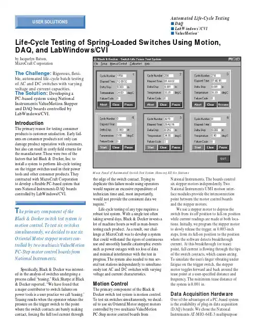
National Instruments. The boards control six stepper motors independently. T wo National Instruments UMI motion inter-face modules provide the interconnection point between the motor control boards and the stepper motors.We use a stepper motor to depress the switch from its off position to full-on position while current readings are made at both loca-tions. Initially, we program the stepper motor to slowly release the trigger, in 0.003-inch steps, from its full-on position to the position where the software detects breakthrough current. At this breakthrough (or tease)point, full current is flowing through the tips of the switch contacts, which causes arcing.T o simulate the user’s finger vibrating under fatigue on the trigger switch, the stepper motor toggles forward and back around the tease point at a user-specified distance and frequency. The minimum tease distance of the system is 0.001 in.Data Acquisition HardwareOne of the advantages of a PC-based system is the availability of plug-in data acquisition (DAQ) boards. We chose the National Instruments AT-MIO-64E-3 multipurposeby Jacquelyn Batson, MicroCraft CorporationThe Challenge: Rigorous,flexi-ble,automated life-cycle batch testing of AC and DC switches with varying voltage and current capacities.The Solution: Developing a PC-based system using National Instruments ValueMotion Stepper and DAQ boards controlled by LabWindows/CVI.IntroductionThe primary reason for testing consumer products is customer satisfaction. Early fail-ures on consumer products not only can damage product reputation with customers,but also can result in costly field returns for the manufacturer. These were two of the factors that led Black & Decker, Inc. to install a system to perform life-cycle testing on the trigger switches used in their power tools and other consumer products. They contracted with MicroCraft Corporation to develop a flexible PC-based system that uses National Instruments DAQ boards controlled by LabWindows/CVI.Specifically, Black & Decker was interest-ed in the analysis of switches undergoing a process called “teasing.” Rick Sharpe at Black & Decker reported, “We have found that a major contributor to switch failures on power tools is a user practice we call ‘teasing.’T easing results when the operator relaxes the pressure on the trigger switch to the point where the switch contacts are barely making contact, forcing the full tool current throughthe edge of the switch contact. T rying to duplicate this failure mode using operators would require an excessive expenditure of technician time and, most importantly,would not provide the consistent data we require.”Life-cycle testing of any type requires a robust test system. With a single test often taking several days, Black & Decker invests a lot of machine hours as well as man-hours testing each product. As a result, our chal-lenge at MicroCraft was to develop a system that could withstand the rigors of continuous use and smoothly handle catastrophic events such as power outages with no loss of data and minimal interference with the test in progress. The system also needed to run sev-eral test stations independently to simultane-ously test AC and DC switches with varying voltage and current characteristics.Motion ControlThe primary component of the Black &Decker switch test system is motion control.T o test six switches simultaneously, we decid-ed to use six Oriental Motor stepper motors controlled by two multiaxis ValueMotion PC-Step motor control boards fromAutomated Life-Cycle Testings DAQs LabWindows ™/CVI s ValueMotion™Life-Cycle Testing of Spring-Loaded Switches Using Motion, DAQ, and LabWindows/CVIT he primary component of theBlack & Decker switch test system is motion control.To test six switches simultaneously,we decided to use six Oriental Motor stepper motors con-trolled by two multiaxis ValueMotion PC-Step motor control boards from National Instruments.Main Panel of Automated Switch Test System Showing All Six StationsSC-2070 termination breadboard to provide connections to the analog signals because it provides a cold-junction reference signal for the thermocouple input.System SoftwareWe chose National Instruments LabWindows/CVI as our software environment. With its special features, we could satisfy the requirements for a graphical user interface and yet main-tain the speed necessary to test six switches simultaneously. The flexible LabWindows environment also made it easy to incorporate on-line help and a manual control ing the manual control mode, Black &Decker engineers can use the system as a laboratory tool for characterizing newDAQ board and AT-AO-6 analog output board; these DAQ boards easily handle the high-speed measurements and control signals. For each switch under test, the system acquires load, no-load, and locked-rotor current measurements; temperature measurements; and voltage measurements.The system also uses analog outputs to drive hysteresis brakes (or dynamometers) that apply load. We used the National Instrumentsswitches, in addition to its customary use as a test system. The system stores all test data points and test setup information to file in standard spreadsheet or SPC-compatible format. T o simplify backups and data analysis,all files are accessible over Black & Decker’s network via a plug-in Ethernet board.SummaryWith the automated switch test system, Black & Decker can perform consistent, reliable testing on the large variety of switch-es used in their consumer products and can maintain standardized test data. Black &Decker has saved thousands of man-hours thanks to the speed, accuracy, and data stor-age capabilities of the National Instruments-based system. In addition, because of the inherent flexibility of the system, we easily added the manual mode –as a result, Black & Decker received a laboratory analysis tool as well as an automated life-cycle test system.1For more information, contact Jacquelyn Batson,MicroCraft Corporation,3209-154 Gresham Lake Road, Raleigh, NC 27615tel (919) 872-2272, fax (919) 872-5822 **********************W e chose the National InstrumentsA T-MIO-64E-3 multipurpose DAQ board and A T-AO-6 analog output board; these DAQ boards easily handle the high-speed measurements and control signals.B lack & Decker has saved thousandsof man-hours thanks to the speed,accuracy,and data storage capabili-ties of the National Instruments-based system.In addition,because of the inherent flexibility of the system,we easily added the manual mode –as a result,Black & Decker received a laboratory analysis tool as well as an automated life-cycle test system.Control Panel for T est StationU.S.Corporate Headquarters • Tel:(512) 794-0100 • Fax:(512)683-9300•****************•Branch Offices:Australia 03 9879 5166 • Austria ***********•Belgium 02 757 00 20 • Brazil 000 811 781 0559 • Canada 905 785 0085 • China ***********• Denmark 45 76 26 00Finland 09 725 725 11 • France 01 48 14 24 24 • Germany 089 741 31 30 • Greece 30 1 42 96 562 • Hong Kong 2645 3186 • India 91805275406 • Israel 03 6120092 • Italy 02 413091Japan 03 5472 2970 • Korea 02 596 7456 • Mexico 001 800 010 0793 • Netherlands 0348 433466 • New Zealand 09 914 0488 • Norway 32 27 73 00 • Singapore 2265886 • Spain 91 640 0085Sweden 08 587 895 00 • Switzerland 056 200 51 51 • Taiwan 02 2377 1200 • U.K.01635 523545© Copyright 1999 National Instruments Corporation.All rights reserved.Product and company names listed are trademarks or trade names of their respective companies.361589A-01 051099。
目录前言 (1)1概述 (2)1.1产品介绍 (2)1.2特性 (2)1.3应用领域 (2)1.4 产品命名规则 (2)2性能指标 (3)2.1电气特性 (3)2.2使用环境 (3)3安装 (4)3.1安装尺寸 (4)3.2安装方法 (4)4端口与接线 (5)4.1接线示意图 (5)4.2端口定义 (6)4.2.1状态指示灯 (6)4.2.2电源端口 (6)4.2.3输入/输出端口 (6)4.2.4拨码开关 (6)4.3控制信号连接 (7)4.3.1输入信号 (7)4.3.2输出信号 (7)4.3.3输入信号波形时序图 (8)4.4拨码开关设定 (8)4.4.1电机旋转方向设定 (8)4.4.2细分设定 (8)5电机规格 (10)5.1技术规格 (10)6报警排除 (11)7版本修订历史 (12)8保修及售后服务 (13)8.1保修 (13)8.2售后服务 (13)前言感谢您使用本公司脉冲型集成式电机。
在使用本产品前,请务必仔细阅读本手册,了解必要的安全信息、注意事项以及操作方法等。
错误的操作可能引发极其严重的后果。
声明本产品的设计和制造不具备保护人身安全免受机械系统威胁的能力,请用户在机械系统设计和制造过程中考虑安全防护措施,防止因不当的操作或产品异常造成事故。
由于产品的改进,手册内容可能变更,恕不另行通知。
用户对产品的任何改装我公司将不承担任何责任。
阅读时,请注意手册中的以下标示:注意:提醒您注意文字中的要点。
小心:表示错误的操作可能导致人身伤害和设备损坏。
本用户手册所述内容仅适用于以下机型:型号电机长度(mm)ESS86-P1x 65ESS86-P2x 80ESS86-P3x 971概述1.1产品介绍ESS86-P系列脉冲型集成电机采用新一代32位DSP控制技术和功角控制技术,最高转速可达3000rmp以上,且高速力矩衰减远低于普通开环驱动器,可大幅提升步进电机的高速性能和力矩使用率,有效降低电机发热和振动,从而提升机器的加工效率和精度。
Instruction Manual3-axis Step Motor Controller (EtherNet / IP TM type) Series JXC92The intended use of the 3-axis step motor controller is to control the operation of electric actuators.1 Safety InstructionsThese safety instructions are intended to prevent hazardous situations and/or equipment damage. These instructions indicate the level of potential hazard with the labels of “Caution,” “Warning” or “Danger.” They are all important notes for safety and must be followed in addition to International Standards (ISO/IEC) *1), and other safety regulations. *1)ISO 4414: Pneumatic fluid power - General rules relating to systems. ISO 4413: Hydraulic fluid power - General rules relating to systems.IEC 60204-1: Safety of machinery - Electrical equipment of machines. (Part 1: General requirements)ISO 10218-1: Manipulating industrial robots -Safety.etc.This manual contains essential information for the protection of users and others from possible injury and/or equipment damage.∙ Read this manual before using the product, to ensure correct handling, and read the manuals of related apparatus before use. ∙ Keep this manual in a safe place for future reference.∙ To ensure safety of personnel and equipment the safety instructions in this manual must be observed, along with other relevant safety practices.not avoided, will result in death or serious injury.Warning∙ The compatibility of the product is the responsibility of the person who designs the equipment or decides its specifications. ∙ Since the product specified here is used under various operating conditions, its compatibility with specific equipment must be decided by the person who designs the equipment or decides its specifications based on necessary analysis and test results. The expected performance and safety assurance of the equipment will be the responsibility of the person who has determined its compatibility with the product. This person should also continuously review all specifications of the product referring to its latest catalogue information, with a view to giving due consideration to any possibility of equipment failure when configuring the equipment.∙ Only personnel with appropriate training should operate machinery and equipment.The product specified here may become unsafe if handled incorrectly.The assembly, operation and maintenance of machines or equipment including our products must be performed by an operator who is appropriately trained and experienced.∙ Do not service or attempt to remove product and machinery/equipment until safety is confirmed.1) The inspection and maintenance of machinery/equipment should only be performed after measures to prevent falling or runaway of the driven objects have been confirmed.2) When the product is to be removed, confirm that the safety measures as mentioned above are implemented and the power from any appropriate source is cut, and read and understand the specific product precautions of all relevant products carefully.3) Before machinery/equipment is restarted, take measures to prevent unexpected operation and malfunction.∙ Contact SMC beforehand and take special consideration of safety measures if the product is to be used in any of the following conditions.1) Conditions and environments outside of the given specifications, or use outdoors or in a place exposed to direct sunlight.2) Installation on equipment in conjunction with atomic energy, railways, air navigation, space, shipping, vehicles, military, medical treatment, combustions and recreation, or equipment in contact with food and beverages, emergency stop circuits, clutch and brake circuits in press applications, safety equipment or other applications unsuitable for the standard specification described in the product catalogue.3) An application which could have negative effects on people, property or animals, requiring special safety analysis.4) Use in an interlock circuit, which requires the provision of double interlock for possible failure by using a mechanical protective function, and periodical checks to confirm proper operation.∙ Always ensure compliance with relevant safety laws and standards.All electrical work must be carried out in a safe manner by a qualified person in compliance with applicable national regulations.Caution∙ The product is provided for use in manufacturing industries.This product may cause interference if used in residential premises. The product herein described is basically provided for peaceful use in manufacturing industries.If considering using the product in other industries, consult SMC beforehand and exchange specifications or a contract if necessary. If anything is unclear, contact your nearest sales branch.2 Specificationsdrive power supply.Note 2) Power consumption depends on the actuator connected. Refer to theactuator specifications for further details.Note 3) Applicable to non-magnetizing lock .2 Specifications - continued3 Installation3.1 InstallationWarningDo not install the product unless the safety instructions have been read and understood. (1) MountingThere are two ways to mount the controller, direct mounting with screws and DIN rail mounting. Controller mounting methods are shown below.(a) Direct Mounting with four M5 screws(b) DIN rail mountingThe figure below shows how to mount the DIN rail mounting brackets.Secure the DIN rail mounting bracket using the mounting screws (M5 x 8) two places on each side (4 places on both sides). (Appropriate tightening torque: 3.0 Nm)Secure the DIN rail mounting bracket using the holding screws (M5 x 14), one place on each side (2 places on both sides). Tighten for approximately 2 threads. Do not tighten completely.3 Installation - continuedThe figure below shows how to mount the controller to the DIN rail. Hook part A on to the DIN rail. Press part B on to the DIN rail and tighten the holding screws (M5 x 14).(Appropriate tightening torque: 0.4 to 0.6Nm)(2) GroundingFit the grounding cable with crimped terminal between the M3 screw and shakeproof washer as shown below and tighten the screw.Power supply connector ∙ Connector specificationsThe power supply connector type included is shown below. (1) Motor drive power connector : M PWRManufactured by Phoenix Contact (Part number MSTB2,5/2-STF-5,08)Note 1) Motor drive power supply (-) and control power supply (-) are connected in the controller.Prepare the electrical wiring according to the following specifications (to be prepared by the user).Mounting screw M5X8(Included with DIN rail mounting bracket) Tightening torque: 3.0 [Nm]Holding screws M5X14 (Included with DIN rail mounting bracket)Tightening torque: 0.4 to 0.6 [Nm]Part APart BHolding screw M5X140V M24VORIGINAL INSTRUCTIONSRefer to Declaration of Conformity for relevant DirectivesMounting screw (M5) 4pcs. (prepared by customer)M3 screw Shakeproof washerGrounding cable (with crimped terminal)L K R L S 3 E M GL K R L S 1 0V C 24V L K R L S 2When the wire is inserted into the motor drive power connector, insert only the stripped part of the wire.(2) Control power supply connector: CI Manufactured by Phoenix Contact (Part number FK-MC0,5/6-ST-2,5)the controller.Prepare the electrical wiring according to the following specifications (to be prepared by the user).When the wire is inserted into the control power supply connector, insert only the stripped part of the wire. 3.2 EnvironmentWarning∙ Do not use in an environment where corrosive gases, chemicals, salt water or steam are present.∙ Do not use in an explosive atmosphere.∙ Do not expose to direct sunlight. Use a suitable protective cover.∙ Do not install in a location subject to vibration or impact. Check the product specifications.∙ Do not mount in a location exposed to radiant heat. 3.3 PipingCaution∙ Before piping make sure to clean up chips, cutting oil, dust etc.∙ When installing piping or fittings, ensure sealant material does not enter inside the port. When using seal tape, leave 1 thread exposed on the end of the pipe/fitting.∙ Tighten fittings to the specified tightening torque. 3.4 LubricationCaution∙ SMC products have been lubricated for life at manufacture, and do not require lubrication in service.∙ If a lubricant is used in the system, use turbine oil Class 1 (no additive), ISO VG32. Once lubricant is used in the system, lubrication must be continued because the original lubricant applied during manufacturing will be washed away.Initial Setting Method • Controller setting (IP address setting)IP address setting is necessary to distinguish the controller on the EtherNet/IP network. The IP address is set by the rotary switches on the controller. Turn OFF the power supply while setting the switches.Use a small flat blade screwdriver of the size shown below when setting the rotary switches.< Size > Width L: 2.0 to 2.4 [mm], Thickness W: 0.5 to 0.6 [mm]provided by Rockwell Automation. Enable DHCP (labelled 1 below)Information including IP address can be obtained from BOOTP/DHCP Server. If the power is supplied again in this state, the controller will try to obtain the information including IP address again. Disable BOOTP/DHCP(labelled 2 below)Information including IP address is not obtained from BOOTP/DHCP Server. Previous setting can be held if power is supplied under this condition.Note 2) Obtain IP address from DHCP Server. Obtained IP address is lost when power supply is disconnected.5 How to Ordercable (Example: LEFS16B-100B-S1)Note) Refer to the SMC website for graphs of speed and transferred workload of electric actuators with the "LECPA" controller.(1) Direct mounting(2) DIN rail mounting7 Maintenance7.1 General MaintenanceCaution∙ Not following proper maintenance procedures could cause the product to malfunction and lead to equipment damage.∙ If handled improperly, compressed air can be dangerous. Maintenance of pneumatic systems should be performed only by qualified personnel.∙ Before performing maintenance, turn off the power supply and be sure to cut off the supply pressure. Confirm that the air is released to atmosphere.∙ After installation and maintenance, apply operating pressure and power to the equipment and perform appropriate functional and leakage tests to make sure the equipment is installed correctly.∙ If any electrical connections are disturbed during maintenance, ensure they are reconnected correctly and safety checks are carried out as required to ensure continued compliance with applicable national regulations.∙ Do not make any modification to the product.∙ Do not disassemble the product, unless required by installation or maintenance instructions.8 Limitations of Use8.1 Limited warranty and Disclaimer/Compliance Requirements ∙ The product used is subject to the following “Limited warranty and Disclaimer” and “Compliance Requirements”. Read and accept them before using the product . ∙ Limited warranty and Disclaimer1) The warranty period of the product is 1 year in service or 1.5 years after the product is delivered, whichever is first (1). Also, the product may have specified durability, running distance or replacement parts. Please consult your nearest sales branch.2) For any failure or damage reported within the warranty period which is clearly our responsibility, a replacement product or necessary parts will be provided.This limited warranty applies only to our product independently, and not to any other damage incurred due to the failure of the product. 3) Prior to using SMC products, please read and understand the warranty terms and disclaimers noted in the specified catalogue for the particular products. (1)Vacuum pads are excluded from this 1 year warranty.A vacuum pad is a consumable part, so it is warranted for a year after it is delivered. Also, even within the warranty period, the wear of a product due to the use of the vacuum pad or failure due to the deterioration of rubber material are not covered by the limited warranty.∙ Compliance Requirements1) The use of SMC products with production equipment for the manufacture of weapons of mass destruction (WMD) or any other weapon is strictly prohibited.2) The exports of SMC products or technology from one country to another are governed by the relevant security laws and regulations of the countries involved in the transaction. Prior to the shipment of a SMC product to another country, assure that all local rules governing that export are known and followed.Caution∙ SMC products are not intended for use as instruments for legal metrology.Measurement instruments that SMC manufactures or sells have not been qualified by type approval tests relevant to the metrology (measurement) laws of each country.Therefore, SMC products cannot be used for business or certification ordained by the metrology (measurement) laws of each country.9 ContactsKeynes, Buckinghamshire MK8 0ANURL : http// (Global) http// (Europe) 'SMC Corporation, Akihabara UDX15F, 4-14-1, Sotokanda, Chiyoda-ku, Tokyo 101 0021Specifications are subject to change without prior notice from the manufacturer. © 2018 SMC Corporation All Rights Reserved. Template DKP50047-F-085GJ X C 9 2 Electric equipmentMountingControl Controller type 9 Ethernet/IP3 axis type 7Direct mounting8DIN rail7mmφ3.4 o r l e s s8mmφ2.0 o r l e s sIP address 5.5 M o u n t i n g h o l eDIN rail mounting bracket。

目录1 题目.............................................................2 电路原理图的设计.................................................2.1 步进电机控制电路原理图......................................2.2 LCD显示模块.................................................2.3 L297/298电机驱动模块……………………………………………………2.4 晶振电路和复位电路………………………………………………………2.5 键盘控制模块(加速、减速、正转、反转)................................3 软件系统设计......................................................3.1 软件系统的流程结构..........................................3.2 主程序bujindianji.c模块....................................3.3头文件reg52.h程序模块.......................................3.4 头文件1602.h程序模块.....................................3.5头文件intrins.h程序模块.....................................4 仿真及调试........................................................总论..............................................................参考文献..........................................................致谢.............................................................1题目: 步进电机的单片机控制功能要求:用MCS-51系列单片机作为控制器;采用两相双极性步进电机为控制对象;采用L297/298驱动芯片为步进电机驱动器;用加速、减速、正转、反转4个键进行相应的控制;用LCD 显示步进的电机的工作状态。
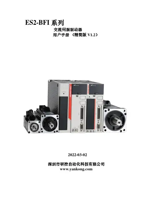
ES2-BFI系列交流伺服驱动器用户手册(精简版 V1.2)2022-03-02深圳市研控自动化科技有限公司目录目录 (1)第一章伺服系统选型 (2)1.1 驱动器规格 (2)1.2 伺服电机及驱动器型号说明 (3)1.3 伺服驱动器和伺服电机配套一览表 (4)1.4 配套电机参数 (4)1.5 配套线缆 (5)1.6 配件包 (7)第二章产品外形尺寸及安装 (8)2.1 伺服驱动器外形尺寸 (8)2.2 伺服驱动器的安装 (8)第三章伺服驱动器与电机连接 (9)3.1 系统结构图 (9)3.2 主回路 (10)3.3 动力线及抱闸接口 (10)3.4编码器接口 (10)3.5 控制信号CN1 (12)3.6 通信信号 (19)第四章面板显示 (20)4.1 面板操作器说明 (20)第五章控制 (23)5.1 基本控制 (23)5.2 位置控制模式 (35)5.3 速度控制模式 (66)第六章运行性能调整 (73)6.1 概述 (73)6.2 离线惯量辨识 (73)6.3 增益调整 (76)6.4 指令滤波调整 (79)6.5 不同模式下的调整参数 (79)第七章辅助功能 (81)7.1.JOG运行 (81)7.2 报警复位 (82)7.3 参数初始化 (83)7.4 数字信号强制输入输出功能 (84)第八章故障及处理 (86)8.1 故障诊断及处理措施 (86)8.2 警告的原因及处理措施 (88)第九章参数一览 (89)9.1参数组号 (89)9.2各组参数 (90)附录A:版本变更记录 (110)第一章伺服系统选型1.1 驱动器规格表1-1 ES2 BFI系列伺服驱动器基本规格1.2 伺服电机及驱动器型号说明1.2.1驱动器型号说明ES2 - 04 - B F I - XX图1-1 驱动器命名规则1.2.2伺服电机型号说明ASM J - 08 - 10 30 B - U 3 2 1 XX图1-2 电机命名规则1.3 伺服驱动器和伺服电机配套一览表表1-2 伺服驱动器与电机配套表1.4 配套电机参数表1-3 电机电机参数表1.5 配套线缆电机动力线命名规则如下图1-3 动力线命名规则电机动力线结构图如下表。
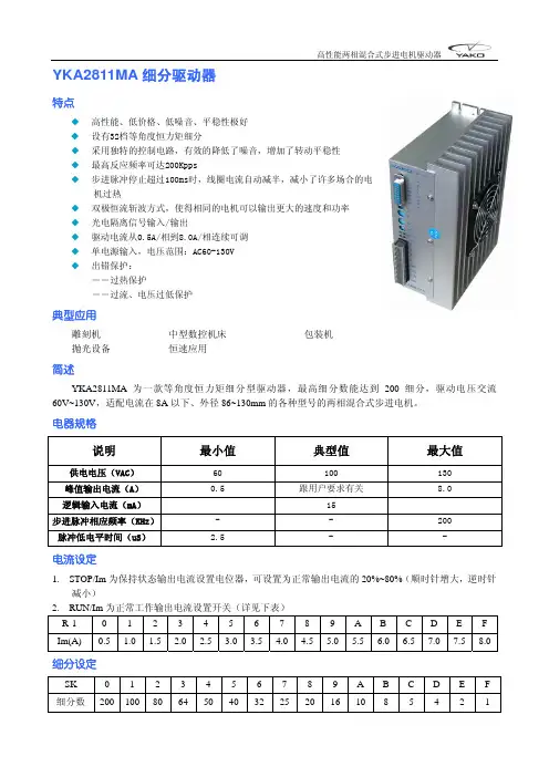
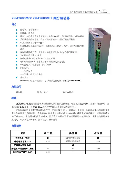
YKA2811MA细分驱动器特点◆ 高性能、低价格、低噪音、平稳性极好◆ 设有32档等角度恒力矩细分◆ 采用独特的控制电路,有效的降低了噪音,增加了转动平稳性◆ 最高反应频率可达200Kpps◆ 步进脉冲停止超过100ms时,线圈电流自动减半,减小了许多场合的电机过热◆ 双极恒流斩波方式,使得相同的电机可以输出更大的速度和功率◆ 光电隔离信号输入/输出◆ 驱动电流从0.5A/相到8.0A/相连续可调◆ 单电源输入,电压范围:AC60-130V◆ 出错保护:――过热保护――过流、电压过低保护典型应用雕刻机中型数控机床包装机抛光设备恒速应用简述YKA2811MA为一款等角度恒力矩细分型驱动器,最高细分数能达到200细分,驱动电压交流60V~130V,适配电流在8A以下、外径86~130mm的各种型号的两相混合式步进电机。
电器规格说明 最小值 典型值 最大值 供电电压(VAC) 60 100 130峰值输出电流(A) 0.5 跟用户要求有关 8.0逻辑输入电流(mA) 15步进脉冲相应频率(KHz)- - 200脉冲低电平时间(uS) 2.5 - -电流设定1. STOP/Im为保持状态输出电流设置电位器,可设置为正常输出电流的20%~80%(顺时针增大,逆时针减小)2. RUN/Im为正常工作输出电流设置开关(详见下表)R-1 0 1 2 3 4 5 6 7 8 9 A B C D E F Im(A) 0.5 1.0 1.5 2.0 2.5 3.0 3.5 4.0 4.5 5.0 5.5 6.0 6.5 7.0 7.58.0细分设定SK 0 1 2 3 4 5 6 7 8 9 A B C D E F 细分数200 100 8064 50 4032252016108 5 4 2 1DIP开关功能设定DP1 OFF:接受外部脉冲ON :驱动器内部自发7.5KHz脉冲DP2 OFF:脉冲信号+方向信号控制方式ON :正向脉冲+反向脉冲控制方式驱动器接线示意图输入信号波形时序图安装尺寸(单位:mm)指示灯和电位器功能说明标记符号 功 能 注 释 PWR 电源指示灯 驱动器通电时,绿色指示灯亮。
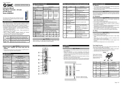
Instruction ManualStep Motor Controller – CC-Link(24 VDC Servo)Series JXCM1##-#The intended use of the step motor controller is to controlthe movement of an electrical actuator whilst connectedto the CC-Link protocol.These safety instructions are intended to prevent hazardous situations and/or equipment damage. These instructions indicate the level of potential hazard with the labels of “Caution,” “Warning” or “Danger.”They are all important notes for safety and must be followed in additionto International Standards (ISO/IEC) *1), and other safety regulations.IEC 60204-1: Safety of machinery - Electrical equipment of machines. (Part 1: General requirements)ISO 10218-1: Robots and robotic devices - Safety requirements for industrial robots - Part 1: Robots.•Refer to product catalogue, Operation Manual and Handling Precautions for SMC Products for additional information.• Keep this manual in a safe place for future reference.Caution Caution indicates a hazard with a low level of risk which, ifnot avoided, could result in minor or moderate injury.Warning Warning indicates a hazard with a medium level of riskwhich, if not avoided, could result in death or serious injury.Danger Danger indicates a hazard with a high level of risk which, ifnot avoided, will result in death or serious injury.Warning•Always ensure compliance with relevant safety laws and standards.•All work must be carried out in a safe manner by a qualified person in compliance with applicable national regulations.2.1 General specificationsItem SpecificationsCompatible motor Step motor (servo 24 VDC)Power supply voltage24 VDC +/-10%(motor drive control, stop, lock brake release).Current consumption 3A (Peak 5A) maximumCompatible encoderBattery-less absolute encoder (resolution: 4096 pulses / rotation)Serial communication RS485Locking Unlocking terminal (applicable to non-exitationmagnetizing lock)Cable length Actuator cable: 20 m maximum Cooling method Air-cooling type Operatingtemperature0o C to 55o C (No freezing) Storage temperature -10o C to 60o C (No freezing) Operating humidity 90% RH or less (No condensation)Insulation resistance50 MΩ (500 VDC)between the external terminals and caseWeight170 g (Direct mounting type)190 g (DIN rail mounting type)2.2 CC-Link specificationsWarningSpecial products (-X) might have specifications different from thoseshown in this section. Contact SMC for specific drawings.3 Name and function of individual parts4 Installation4.1 InstallationWarning•Do not install the product unless the safety instructions have been readand understood.•Design the installation so that the temperature surrounding thecontroller is 55o C max. Leave enough space between the controllersso that the operating temperature of the controllers remains within thespecification range.•Mount the controller vertically with 30 mm minimum space on the topand bottom of the controller as shown below.•Allow 60 mm minimum space between the front of the controller and adoor (lid) so that the connectors can be connected and disconnected.4.2 Mounting•The controller can be direct mounted (model JXCM17#) using screwsor mounted on a DIN rail (model JXCM18#).•When using DIN rail mounting, hook the controller on the DIN rail andpress the lever down to lock it.CautionIf the mounting surface for the controller is not flat or is uneven, excessivestress may be applied to the enclosure, which can cause failure. Be sureto mount on a flat surface.4.3 EnvironmentWarning•Do not use in an environment where corrosive gases, chemicals, saltwater or steam are present.•Do not use in an explosive atmosphere.•Do not expose to direct sunlight. Use a suitable protective cover.•Do not install in a location subject to vibration or impact in excess ofthe product’s specifications.•Do not mount in a location exposed to radiant heat that would result intemperatures in excess of the product’s specifications.•Avoid mounting the controller near a vibration source, such as a largeelectromagnetic contactor or circuit breaker on the same panel.•Do not use in an environment with strong magnetic fields present.4.4 WiringCaution•Do not perform wiring while the power is on.•Confirm proper insulation of wiring.•Do not route wires and cables together with power or high voltagecables.•Keep wiring as short as possible to prevent interference fromelectromagnetic noise and surge voltage.•Do not use an inrush current limited type of power supply for thecontroller.•Do not connect multiple wires to one connector terminal.Power Supply ConnectorWire the power supply cable to the power supply plug connector, theninsert it into connector PWR on the controller.•Use special screwdriver (Phoenix Contact No. SZS0.4×2.0) to open /close lever and insert the wire into the connector terminal.•Applicable wire size: 20 AWG (0.5 mm2).PinNo.Terminal Function Description1 C24V Power supply (+) Positive control power.2 M24V Motor power (+)Positive power for theactuator motor suppliedvia the controller.3 EMG Stop (+)Positive power foremergency stop signal4 0V Common power (-)Negative common power forM24V, C24V, EMG and LKRLS.5 - NC N/A6 LK RLS Unlocking (+)Positive power for lockrelease.30 mm min. (Direct mounting)50 mm min. (DIN rail mounting)30 mm minimumControllerORIGINAL INSTRUCTIONS②③④⑤⑥⑦⑧⑪①⑨Power Supply Wire specificationsPrepare the wiring according to the following specifications (to be prepared by the user).Communication ConnectorWire the CC-Link communication cable to the communication plug connector, then insert it into connector CN5 on the controller.• Use special screwdriver (Phoenix Contact No. SZS0.6×3.5) to tighten the connector terminal screws. Tightening torque = 0.5 to 0.6 N•m. • Applicable wire size: 12 to 24 AWG (0.2 to 2.5 mm 2)Straight type (LEC-CMJ-S) T-branch type (LEC-CMJ-T)Phoenix Contact No. Phoenix Contact No. MSTB2,5/5-ST-5,08 AU MSTB2,5/5-ST-5,08 AU• The CC-Link system has different terminating resistance requirements depending on the cables used.• Connect a terminating resistor to both ends of the CC-Link main line.Cable typeResistance CC-Link communication cable 110 Ω ±5% 1/2W CC-Link high performance cable130 Ω ±5% 1/2W4.5 Ground connection• Place a ground cable with crimped terminal under one of the M4 mounting screws with a shakeproof washer and tighten the screw.CautionThe M4 screw, cable with crimped terminal and shakeproof washer must be prepared by the user.The controller must be connected to Ground to reduce noise. If higher noise resistance is required, ground the 0 V (signal ground). When grounding the 0 V, avoid flowing noise from ground to 0 V.• A dedicated Ground connection must be used. Grounding should be to a D-class ground (ground resistance of 100 Ω maximum).• The cross-sectional area of the ground cable shall be 2 mm 2 minimum. • The Grounding point should be as near as possible to the controller. Keep the grounding cable as short as possible.5.1 Switch settingSet the CC-Link address and the CC-Link communication speed using the STATION NO, and B RATE rotary switch.• STATION NO. switch Switch name Set range DescriptionSTATION NO. X10 01 to 64Set upper bits of the station STATION NO. X1Set lower bits of the stationThe CC-Link address setting at the time of the factory shipment is set in “01".• B RATE (Baud Rate) switchThe CC-Link communication speed (Baud Rate) setting at the time of the factory shipment is set in “0" (156 kbps).*1) When the setting is 1 for the Occupied number of stations, the setting of Occupied number of stations will reset to 2 (default) by applying power with the B RATE switch set to 9.6 LED DisplayRefer to the table below for details of the LED status.LEDDescriptionPWROFFPower is not supplied Green LED is ON Power is suppliedGreen LED is flashingEEPROM memory writing ALMOFFNormal operationRed LED is ONController Alarm generated L ERROFFNormal operation Red LED is ON Error is generated Red LED is flashingL RUN OFFCC-Link Communication disconnectedGreen LED is ON CC-Link Communicating Green LED is flashingError is generated7 How to OrderRefer to the catalogue on the SMC website (URL: https:// ) for the How to Order information.8 Outline Dimensions (mm)Refer to the drawings / operation manual on the SMC website (URL: https:// ) for outline dimensions.9.1 General MaintenanceCaution• Not following proper maintenance procedures could cause the product to malfunction and lead to equipment damage.• Before performing maintenance, turn off the power supply. Check the voltage with a tester 5 minutes after the power supply is turned OFF. • If any electrical connections are disturbed during maintenance, ensure they are reconnected correctly and safety checks are carried out as required to ensure continued compliance with applicable national regulations.• Do not make any modification to the product.• Do not disassemble the product, unless required by installation or maintenance instructions.Caution• Maintenance should be performed according to the procedure indicated in the Operation Manual.• When equipment is serviced, first confirm that measures are in place to prevent dropping of work pieces and run-away of equipment, etc, then cut the power supply to the system. When machinery is restarted, check that operation is normal with actuators in the correct position.Warning• Perform maintenance checks periodically.• Confirm wiring and screws are not loose. Loose screws or wires may cause unexpected malfunction.• Conduct an appropriate functional inspection and test after completing maintenance. In case of any abnormalities (if the actuator does not move, etc.), stop the operation of the system. Otherwise, an unexpected malfunction may occur and it will become impossible to ensure safety. Operate an emergency stop instruction to confirm safety. • Do not put anything conductive or flammable inside of the controller. • Ensure sufficient space around the controller for maintenance.10 Limitations of Use10.1 Limited warranty and Disclaimer/Compliance Requirements Refer to Handling Precautions for SMC Products.11 Product disposalThis product shall not be disposed of as municipal waste. Check your local regulations and guidelines to dispose of this product correctly, in order to reduce the impact on human health and the environment.12 ContactsRefer to or www.smc.eu for your local distributor / importer.URL: https:// (Global) https://www.smc.eu (Europe) SMC Corporation, 4-14-1, Sotokanda, Chiyoda-ku, Tokyo 101-0021, Japan Specifications are subject to change without prior notice from the manufacturer. © 2021 SMC Corporation All Rights Reserved. Template DKP50047-F-085M5 4 3 2 154 3 2 1。
YKA2404MA/ YKA2404MB 细分驱动器特点◆ 低噪音、平稳性极好◆ 高性能、低价格◆ 设有12/8档等角度恒力矩细分,最高200细分,使运转平滑,分辨率提高◆ 采用独特的控制电路,有效的降低了噪音,增加了转动平稳性◆ 最高反应频率可达200Kpps◆ 步进脉冲停止超过100ms时,线圈电流自动减半,减小了许多场合的电机过热◆ 双极恒流斩波方式,使得相同的电机可以输出更大的速度和功率◆ 光电隔离信号输入/输出◆ 驱动电流从0.1A/相到4.0A/相连续可调◆ 可以驱动任何4.0A相电流以下两相混合式步进电机◆ 单电源输入,电压范围:DC12-40V◆ 出错保护:――过热保护――过流、电压过低保护◆ 体积小巧YKA2404MA(B)是一款经济、小巧的步进驱动器,体积为25x136x92mm2。
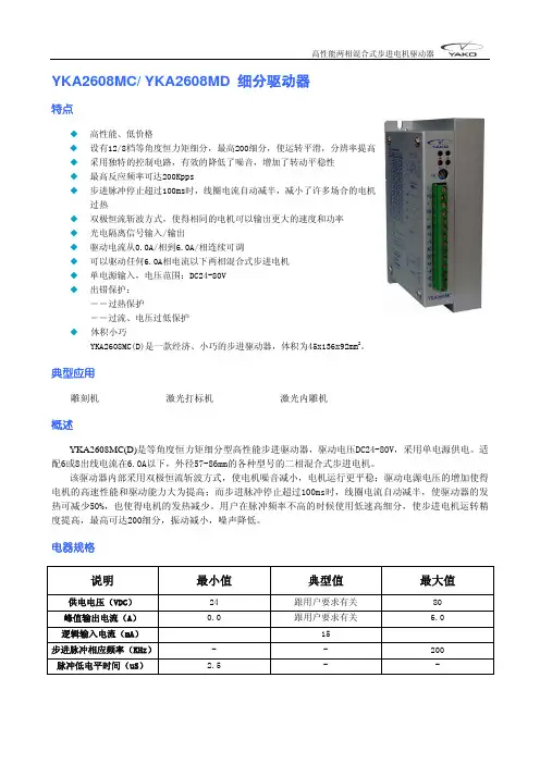
典型应用雕刻机激光打标机激光内雕机概述YKA2404MA(B)是等角度恒力矩细分型高性能步进驱动器,驱动电压DC12-40V,采用单电源供电。
适配电流在4.0A以下,外径42-86mm的各种型号的二相混合式步进电机。
该驱动器内部采用双极恒流斩波方式,使电机噪音减小,电机运行更平稳;驱动电源电压的增加使得电机的高速性能和驱动能力大为提高;而步进脉冲停止超过100ms时,线圈电流自动减半,使驱动器的发热可减少50%,也使得电机的发热减少。
用户在脉冲频率不高的时候使用低速高细分,使步进电机运转精度提高,最高可达200细分,振动减小,噪声降低。
电器规格说明 最小值 典型值 最大值 供电电压(VDC) 12 跟用户要求有关 40峰值输出电流(A) 0.1 跟用户要求有关 4.0逻辑输入电流(mA) 15步进脉冲相应频率(KHz)- - 200脉冲低电平时间(uS) 2.5 - -工作电流设定示意图功能设定示意图输入信号波形时序图驱动器信号示意图驱动器接线示意图安装尺寸(单位:mm)z采用侧面安装,散热效果较好YKA2404MA细分设定表细分数 1 2 4 5 8 1020254050100200 200 200 200200 D6 ON OFF ON OFF ON OFF ON OFF ON OFF ON OFF ON OFF ON OFF D5 ON ON OFF OFF ON ON OFF OFF ON ON OFF OFF ON ON OFF OFF D4 ON ON ON ON OFF OFF OFF OFF ON ON ON ON OFF OFF OFF OFF D3 ON ON ON ON ON ON ON ON OFF OFF OFF OFF OFF OFF OFF OFF ON,双脉冲:PU为正向步进脉冲信号,DR为反向步进脉冲信号D2OFF,单脉冲:PU为步进脉冲信号,DR为方向控制信号D1 自检测开关(OFF时接收外部脉冲,ON时驱动器内部发7.5kHz脉冲) YKA2404MB细分设定表细分数 1 2 4 8 16 32 64128 D6 ON OFF ON OFF ON OFF ON OFF D5 ON ON OFF OFF ON ON OFF OFF D4 ON ON ON ON OFF OFF OFF OFF D3 无效ON,双脉冲:PU为正向步进脉冲信号,DR为反向步进脉冲信号D2OFF,单脉冲:PU为步进脉冲信号,DR为方向控制信号D1 自检测开关(OFF时接收外部脉冲,ON时驱动器内部发7.5kHz脉冲) 指示灯和电位器功能说明标记符号 功 能 注 释PWR 电源指示灯 驱动器通电时,绿色指示灯亮。
步进电机可编程控制器使用说明一、系统特点●控制轴数:单轴;●指令特点:任意可编程(可实现各种复杂运行:定位控制和非定位控制);●最高输出频率:40KHz(特别适合控制细分驱动器);●输出频率分辨率:1Hz;●编程条数:99条;●输入点:6个(光电隔离);●输出点:3个(光电隔离);●一次连续位移范围:—7999999~7999999;●工作状态:自动运行状态,手动运行状态,程序编辑状态,参数设定状态;●升降速曲线:2条(最优化);●显示功能位数:8位数码管显示、手动/自动状态显示、运行/停止状态显示、步数/计数值/程序显示、编辑程序,参数显示、输入/输出状态显示、CP脉冲和方向显示;●自动运行功能:可编辑,通过面板按键和加在端子的电平可控制自动运行的启动和停止;●手动运行功能:可调整位置(手动的点动速度和点动步数可设定);●参数设定功能:可设定起跳频率、升降速曲线、反向间隙、手动长度、手动速度、中断跳转行号和回零速度;●程序编辑功能:可任意插入、删除可修改程序。
具有跳转行号、数据判零、语句条数超长和超短的判断功能;●回零点功能:可双向自动回到零点;●编程指令:共14条指令;●外操作功能:通过参数设定和编程,在A操作和B操作端子上加开关可执行外部中断操作;●电源:AC220V(电源误差不大于±15%)。
一、前面板图前面板图包括:1、八位数码管显示2、六路输入状态指示灯3、三路输出状态指示灯4、 CP脉冲信号指示灯5、 CW方向电平指示灯6、按键:共10个按键,且大部分按键为复合按键,他们在不同状态表示的功能不同,下面的说明中,我们只去取功能之一表示按键。
后面板图及信号说明:后面板图为接线端子,包括:1、 CP、CW、OPTP为步进电机驱动器控制线,此三端分别连至驱动器的相应端,其中:CP————步进脉冲信号CW————电机转向电平信号OPTO————前两路信号的公共阳端CP、CW的状态分别对应面板上的指示灯2、启动:启动程序自动运行,相当于面板上的启动键。
康达研控科技TB6600步进电机专用驱动器使用说明TB6600步进电机专用驱动器,高性能,低价格。
!安全注意事项一、简介TB6600步进电机驱动器是一款专业的两相步进电机驱动,可实现正反转控制。
通过S1S2S33位拨码开关选择8档细分控制(1、2、4、8、16),通过S4S5S63位拨码开关选择6档电流控制(0.5A,1A,1.5A,2.0A,2.5A,3.0A, 3.5A,4.0A)。
适合驱动86,57,42,39型两相、四相混合式步进电机。
驱动器具有噪音小,震动小,运行平稳的特点。
产品特点※原装全新日本东芝驱动芯片※电流由拨码开关选择※接口采用高速光耦隔离※八种细分可调※自动半流减少发热量※大面积散热片不惧高温环境使用※抗高频干扰能力强※输入电压防反接保护※过热,过流短路保护※故障红色警示灯输入电压9-42V,推荐使用24V输入电流推荐使用开关电源功率24V/5A输出电流0.5-4.0A最大功耗72W细分1、2、4、8、16温度工作温度-10~45℃;存放温度-40℃~70℃湿度不能结露,不能有水珠气体禁止有可燃气体和导电灰尘重量0.15千克输入输出端说明◆信号输入端PUL+:脉冲信号输入正。
PUL-:脉冲信号输入负。
DIR+:电机正、反转控制正。
DIR-:电机正、反转控制负。
ENA+:电机脱机控制正。
ENA-:电机脱机控制负。
◆电机绕组连接A+:连接电机绕组A+相。
A-:连接电机绕组A-相。
B+:连接电机绕组B+相。
B-:连接电机绕组B-相。
◆电源电压连接VCC:电源正端“+”GND:电源负端“-”注意:DC直流范围:9-32V,不能超过此范围,否则会无法正常工作,甚至损坏驱动器◆输入端接线说明输入信号共有三路,它们是:①步进脉冲信号PUL+,PUL-;②方向电平信号DIR+,DIR-③脱机信号ENA+,ENA-。
输入信号接口有两种接法,用户可根据需要采用共阳极接法或共阴极接法。
共阳极接法:分别将PUL+,DIR+,ENA+连接到控制系统的电源上,如果此电源是+5V则可直接接入,如果此电源大于+5V,则须外部另加限流电阻R,保证给驱动器内部光藕提供8—15mA的驱动电流。