3工艺过程流程图
- 格式:doc
- 大小:78.50 KB
- 文档页数:2


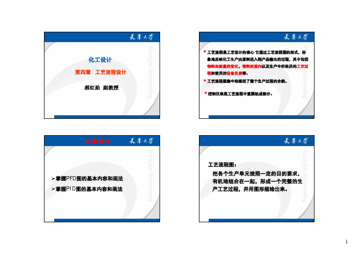
1第四章工艺流程设计郝红勋副教授化工设计★工艺流程是工艺设计的核心,它通过工艺流程图的形式,形象地反映化工生产由原料进入到产品输出的过程,其中包括物料和能量的变化,物料的流向以及生产中所经历的工艺过程和使用的设备仪表等。
★工艺流程图集中地概括了整个生产过程的全貌。
★控制仪表是工艺流程中重要组成部分。
2本章要求掌握PFD 图的基本内容和画法 掌握PID 图的基本内容和画法3工艺流程图:把各个生产单元按照一定的目的要求,有机地组合在一起,形成一个完整的生产工艺过程,并用图形描绘出来。
4工艺流程图分类:工艺流程框图(PBD)工艺物料流程图(PFD)带控制点的工艺流程图(工艺管道及仪表流程图-PID图)Piping and Instrumentation Diagram54.1 工艺流程框图(PBD图)工艺流程示意图也称工艺流程框图通常是用来向决策机构、高级管理部门提供该工艺过程的快速说明,如项目建议书、可行性研究报告中所提供的就是流程示意图。
工艺过程的总体概念用方框流程图按不同的部分表示,每个方框根据不同的详略要求,可以是整个工艺流程的一个部分,也可以是一个操作单元。
6流程示意图一般用细实线矩形框表示,流程线只画出主要物流,用粗实线表示,流程方向用箭头画在流程线上,并加上其他必要的注释等。
图4-17工艺物料流程图在物料衡算和热量衡算后绘制,简称PFD图(Process Flow Diagram)。
此图是以图形与表格相结合的形式来反映物料衡算结果它主要表示出该化工流程中主要设备的物料状态,如温度,压力,流率和组成等。
它可作为设计审查的资料,并作为进一步设计的重要依据,同时也作为日后生产操作的参考。
4.2 工艺物料流程图(工艺物料平衡图)图4-2工艺物料流程图例一、工艺物料流程图的内容1)图形:设备的示意图和流程线。
2)标注:设备的位号、名称及特性数据等。
3)物料平衡表:物料代号、物料名称、组分、流量、压力、温度状态及来源去向 4)标题栏:包括图名、图号、设计阶段等。


环评编写常用工艺及描述流程图1、室内木质家具生产工艺流程成品木质材料胶粘剂图1 室内木质家具生产工艺流程图及产污环节工艺流程说明:1、虚线框内表示污染物排放情况。
2、主要工序说明:(1)开料:按照生产单准备所需要的木料。
该工序会产生木加工粉尘、木材边角料和下料噪声。
(2)机加工:按照生产要求,对已下料的木质材料进行切角、打磨、封边处理,并使用胶粘剂进行组装。
该工序会产生木加工粉尘、木材边角料、组装有机废气和下料噪声。
(3)喷底漆:经前面处理好的半成品进行水性底漆操作,喷漆后在烘干房内烘干。
此工序会产生有机废气和机器噪声。
(4)修色:喷底漆工序有不良品的,使用天那水将底漆洗掉后重新喷漆,该工序会产生有机废气和噪声。
(5)喷面漆:喷好底漆,再用喷枪在木器工件表面喷上一层的面漆,使产品表面更加美观,每条喷漆线均设水帘柜。
此工序会产生有机废气、喷漆噪声和水帘柜浓水。
(6)组装:将组件用螺丝钉组装成成品;此工序会产生噪声。
(7)烘干:喷好漆的木质材料家具在烘干房中烘干,此工序会产生有机废气。
(7)包装:将烘干后的成品家具进行包装,此工序会产生废包装材料。
2、塑胶制品及配件生产工艺流程产品图2 塑胶制品及配件生产工艺流程图及产污环节工艺流程说明:1、虚线框内表示污染物排放情况。
2、主要工序说明:(1)烘干:项目先将外购的塑胶粒原料进行烘干去湿,采用电动空压机对原料进行烘干去湿,使用电能。
(2)注塑:项目配料使用塑胶粒和色粉,其中色粉占0.01%,其余为塑胶粒,使用混料机混合均匀后进行注塑。
注塑机采用电加热,并通过温控装置控制加热温度为140~190℃,该温度不会超过塑料原料热分解温度,注塑件经设备内部循环冷却水间接冷却成型。
(3)装配:将注塑成型的塑胶配件使用胶粘剂进行粘贴成产品,此工序会产生有机废气。
(4)包装:将产品使用包装材料进行包装,此工序会产生废包装材料。
3、五金冲压制品及配件生产工艺流程来料产品图3 五金冲压制品及配件生产工艺流程图及产污环节工艺流程说明:1、虚线框内表示污染物排放情况。
3工艺流程图的绘制(The drawing of 3 process flow chart)3 process flow drawing.Txt I was degraded, and I can't swim until now. I know I was the fastest one before I was born. This article was contributed by zx55107499Ppt documents may experience poor browsing on the WAP side. It is recommended that you select TXT first or download the source file to the local machine.Synthesis process design of polymerSchool of materials science and EngineeringXu lili1Section 5 rendering process flow chartThe basic knowledge of drawing drawing, technological process sketch, process flow chart and piping instrument flow chartBasic knowledge of chemical process drawing1 the basic composition of the drawings2 drawings format3 graphics proportionGraphics should comply with the national standard "the proportion of technical drawing ratio (GB/T1469093) regulations". Stipulation of drawing proportion should be marked in Title column. If some of the main view and view the proportion of different proportion, in a drawing, if some views and the proportion of the different proportion of the main viewin a drawing, the proportion should be marked in the figure, the view above the line fine line. Mark the scale above the view, such as the graph, where the line is a fine solid line. Beta beta alpha alpha alpha 1?? to not according to the proportion of 1: 5 1: 5 1:54 text formatThe writing format of Chinese characters, letters and numbers in drawings should be unified and suitable in size. The writing format of Chinese characters, letters and numbers in drawings should be unified and suitable in size.Layout of engineering drawingsTechnical explanationBreadth linePatternLegendFrameDetail listDetail listDetail table title barFigure 3-11 width and size of drawingTwo process sketch 1 program flow chart: the flow chart can be expressed by block diagram, and the flow chart can be expressed by block diagram,Relationship between. Relationship between.2345Sketch of process flow: sketch of process flow: also called process flow diagram. Material balance diagram process flow chart (PFD) (PFD). Process flow chart (PFD). Piping instrument flow chart (PID) (PID). Piping instrument flow chart (PID).2 process sketch: also called process flow diagram. Sketch of process flow:(symbol of equipment). Equipment schematic diagram (equipment) material pipeline (material piping). Material pipeline (material piping).Thick lines draw all the raw material and the arrow indicates the direction of pipeline, draw all the raw material of pipeline, with thick lines draw all the raw material of pipeline, and the arrow indicates the direction, with thick lines to draw important auxiliary material pipelines. The valve and meter thick lines to draw important auxiliary materials, pipeline valves draw important auxiliary material pipelines. And so on. And so on.(3) text annotation (notes). Text annotation (notes) (notes).The equipment is annotated (code name, name) to annotate the equipment (code name), indicating the name, source and whereabouts of the material entering and leaving the stock. Mark names, sources, whereabouts.3 material flow chart (material balance diagram)The number chart of the material in the whole production process is represented by the chart to represent the quantity balance relationship of the whole process of production, the state parameter and the performance parameter of each stock material. The quantity balance relation, the state parameter and performance parameter of each stock material. Each material has a logistics number (material stream each material has a logistics number number), and corresponds to the material balance table. And corresponding to the material balance table. The top left side box frame or rectangular diamond diamond on the pipeline of logistics, the corresponding diamond frame or rectangle on the pipeline of logistics, corresponding on the pipeline of the corresponding material or pipeline), (above),Material flow in the box or above the material pipeline (left), material flow and various parameters are given in the material balance table. And various parameters are given in the material balance sheet.Three process flow chart process flow diagram(a) schematic diagram of the main content of the material flowand drawing (two) notes (legend and note legend and legend and notes) (note) (three) the title bar and list of the equipment (title Panel and equipment date sheet)(1) the main contents and drawing methods of the material flow diagramThe 1 painting equipment according to the material flow through the main sequence from left to right, in order to draw, the main material flows through the reserve order from left to right in turn on drawing, through the order from left to right, the devices do not need to draw a line of the same, just don't draw a draw, a number of production lines don't draw; equipment, production lines of the same, only need to draw a fine line;2 in proportion to draw the outline and main equipment of each internal node thin lines equipment outline and main characteristics of the internal structure of drawing in proportion. Structural characteristics. Pumps, compressors and other equipment is not drawing in proportion. Table 3-7 the compressor equipment is not drawn to scale. The PFD should be in the size of the equipment list marked equipment; PFD should be in the size of the equipment list of equipment shall be marked in the size of the equipment list marked equipment; the indicating device name (equipment name) and a number (equipment number), the equipment classification code can see table 3-8. The code for classification of equipment may be shown in table, in which the device classification code can be seen, and can be seen in figure 13. Method can be seen in figure 3-13.Table 3-7 common painting equipment2 material pipeline representation methodWith the flow of the solid line in the process flow diagram as a solid line with the pipeline flow with the flow of the solid line in the process flow diagram as the pipeline (material piping) said the flow of logistics and logistics; and said flow and flow of the logistics; each need to define a number of logistics logistics (material stream number), logistics in the diamond shape or rectangular box, you can also write to put the box in the logistics logistics, a diamond or a rectangle on a diamond or a rectangular box in the pipeline pipeline above the top or left or left, top or left in the pipeline, the logistics and material balance in the corresponding logistics No. the key point of operation; the key point of operation in logistics number corresponding; for the key point of operation should also show the logistics point temperature Or pressure, temperature, or pressure. The temperature or pressure of the logistics point.In PFD, the drawing between the material pipeline and the material pipeline and the PFD intersection of the control instrument should be disconnected. The drawing should be broken when crossing. The pipeline open principle: the main pipeline connection, the principle of pipeline disconnected: main materials and auxiliary materials pipeline pipeline connection is disconnected; disconnect the horizontal or vertical line; disconnect pipeline, continuous control line; disconnect the horizontal or vertical line; the pipeline system, continuous meter connections disconnected etc.. Instrument wiring disconnection and so on. 3-14. The main valves and important fittings must be drawn in the material pipeline of PFD. PFDmaterial pipeline must draw the main valve and important pipe material, the pipeline must draw the main valve and important pipe fittings.If a graph can not fully represent the whole process, it can be drawn into multiple process flow charts when the whole process is not completely expressed when a graph can not fully represent the whole process. When the part is disconnected, the drawing process is drawn. In the figure, the inlet and outlet points of the material are represented by a sharp box with a sharp box. The inlet and outlet points of the material pipeline are represented by a sharp box, and the flow chart number and the equipment number of the material coming or going are explained.Flow chart number and equipment position number. Figure 3-153 control scheme representation methodThe main contents of the main content of control scheme and testing, detection and control parameters and control scheme: the main content detection point, control parameters, instrument function, regulating valves, actuators, instrument function, regulating valves, executive structure, instrument installation position. Position, etc.. In the process, the control scheme is breaks in the process flow diagram of the instrument graphics, graphic character control scheme through the instrument regulating valve and actuator graphic symbols, number, regulating valves and actuators of the graphic symbols, the instrument connection said that. Tables, lines, etc..The instrument graphical symbol should indicate the instrument installation position, the test control instrument graphical symbol should indicate the instrument installation position, the test control parameter should indicate the instrument installation position, the instrument function and so on. Function content, instrument function and so on. The instrument graphic symbol consists of the instrument installation position, the graphic symbol and the instrument position number group, the instrument graphic symbol is installed by the instrument, the position symbol and the instrument position number group 16. A. Figure 3-16. The instrument position is composed of letters and numbers. The number of the instrument is composed of letters and numbers. Form。
磺胺间甲氧嘧啶钠注射液生产工艺规程(大容量)目录1 产品概述2 处方和依据3 工艺流程图4 制剂工艺过程及工艺条件5 原辅材料质量标准和检查方法6 中间产品质量标准和检查方法7 成品质量标准和检查方法8 包装规格、包装材料质量标准9 说明书、产品文字说明和标志10 工艺要求11 设备一览表和主要设备生产能力12 技术安全与劳动保护13 劳动组织14 技术经济指标计算15 原辅料消耗定额16 包装材料消耗定额17 动力消耗定额18 综合利用与环境保护目的:制定本标准的目的是规范磺胺间甲氧嘧啶钠注射液生产过程,对一定数量的成品所需的起始原辅料和包装材料,以及工艺、加工说明、技术参数、注意事项等进一步标准化。
适用范围:适用于磺胺间甲氧嘧啶钠注射液生产全过程。
责任人:质量部部长、生产部部长、车间主任。
内容:1产品概述:本品为磺胺间甲氧嘧啶钠的灭菌水溶液。
含磺胺间甲氧嘧啶钠(C11H11N4NaO3S)应为标示量的96.0%~104.0%1.1产品特点:1.1.1性状:本品为无色至微黄色的澄明液体。
1.1.2作用与用途:磺胺类药。
用于各种敏感菌引起的呼吸道、消化道、泌尿道感染及球虫病、猪弓形虫病等。
局部灌注可治疗乳腺炎和子宫内膜炎。
1.1.3用法用量:静脉注射一次量每1Kg体重家畜0.5ml,一日1~2次,连用2-3日。
1.1.4规格:100ml:10g(磺胺间甲氧嘧啶钠)1.1.5贮藏:遮光、密闭保存。
1.1.6停药期:28日1.1.7有效期:二年1.1.8批准文号:2 处方和依据:2.1处方:(1000ml)磺胺间甲氧嘧啶钠100g 硫代硫酸钠 1 g注射用水 至1000ml10000级区100000级区4 制剂工艺过程及工艺条件: 4.1总述:4.1.1按生产指令单领取磺胺间甲氧嘧啶钠原料,在浓配灌中加入计算量70%的注射用水, 再加入计算量的硫代硫酸钠搅拌使溶解;然后加磺胺间甲氧嘧啶钠原料搅拌至完全溶解,粗滤至稀配灌中,加注射用水近全量,调节PH在规定范围内(9.7-10.8),补加注射用水至足量;用孔径为0.45um、0.22um的过滤器(使用前后经过完整性测试合格)精滤,检查澄明度、含量合格后,将药液输送到至灌封岗位,灌装压盖,100℃30分钟灭菌,灯检、贴签包装成规定规格即可。