AMESim热气动库资料
- 格式:pdf
- 大小:379.52 KB
- 文档页数:19


A M E S I M介绍第二章AMESim的应用方法2.1 AMESim简介AMESim表示系统工程高级建模和仿真平台(Advanced Modeling Environment for Simulations of engineering systems)。
它能够从元件设计出发,可以考虑摩擦、油液、和气体的本身特性、环境温度等非常难以建模的部分,直到组成部件和系统进行功能性能仿真和优化,并能够联合其他优秀软件进行联合仿真和优化,还可以考虑控制器在环构成闭环系统进行仿真,使设计出的产品完全满足实际应用环境的要求。
AMESim软件共由四个功能模块组成:AMESim、AMESet、AMECustom、AMERun,另外还有软件帮助模块AMEHelp。
其中,AMESim用于面向对象的系统建模、参数设置、仿真运行和结果分析,是该工具软件的主功能模块,主要工作模式为:按系统原理图建模一确定元件子模型一设定元件参数一仿真运行一结果观测和分析。
AMEest用于构建符合用户个人需求的元件子模型,主要通过两步进行:先设定子模型外部参数情况,系统自动生成元件代码框架,再通过用户的算法编程实现满足用户需要的元件,程序使用C或Fortnar77实现;AMECustom用于对软件提供的元件库中的元件进行改造,但不能深入到元件代码层次,只适用于元件的外部参数特性的改造;AMERun是提供给最终用户的只运行模块,最终用户可以修改模型的参数和仿真参数,执行稳态或动态仿真,输出结果图形和分析仿真结果,但不能够修改模型结构,不能够访问或修改元件代码等涉及技术敏感性的信息。
2.2AMESim的特点1.多学科的建模平台AMESim在统一的平台上实现了多学科领域的系统工程的建模和仿真,模型库丰富,涵盖了机械、液压、控制、液压管路、液压元件设计、液压阻力、气动、热流体、冷却、动力传动等领域,且采用易于识别的标准ISO图标和简单直观的多端口框图,方便用户建立复杂系统及用户所需的特定应用实例。
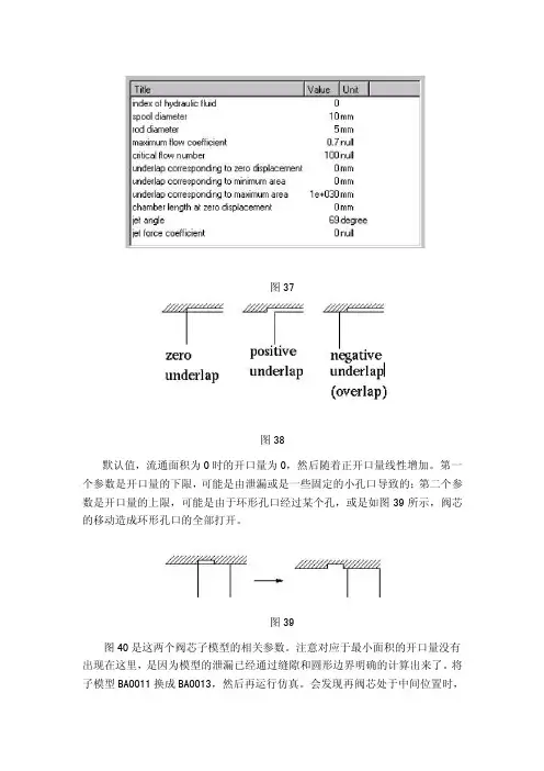
图37图38默认值,流通面积为0时的开口量为0,然后随着正开口量线性增加。
第一个参数是开口量的下限,可能是由泄漏或是一些固定的小孔口导致的;第二个参数是开口量的上限,可能是由于环形孔口经过某个孔,或是如图39所示,阀芯的移动造成环形孔口的全部打开。
图39图40是这两个阀芯子模型的相关参数。
注意对应于最小面积的开口量没有出现在这里,是因为模型的泄漏已经通过缝隙和圆形边界明确的计算出来了。
将子模型BAO011换成BAO013,然后再运行仿真。
会发现再阀芯处于中间位置时,负载孔口存在一个小流量。
这里从P到T液一直有少量泄漏。
试着增大缝隙和圆形边界的半径,然后会发现增大这些参数会增大泄漏量。
图40这个例子的模型将所用问题都高度细化。
对阀门的设计者来说是非常适用的,但对于更多的使用者来说,更简单的方法要更合适一些。
然而许多情况下,阀的动态特性及其控制系统近似为二阶传递函数,通过软件中提供的数据来定义这些参数。
图41就是这样一个高度简化的系统。
动态特性由一个二阶滞后提供,包括自然频率和阻尼系数;位移限制由一个饱和元件来实现;位移的最终值是不同的,并产生一个相应得速度;其他需要用来计算的量是子模型BAO011和BAO012空间上的相关数据。
图412.5 带移动缸体的液压缸通常得液压缸体是固定不动的或可假定为静止。
然而,在其他情况下或是想得到更符合实际的结果就有必要将缸体得运动考虑在内。
HCD中的相对运动子模型可以实现这一要求。
可以用移动缸体来构建一个液压缸模型,并与固定缸进行比较。
系统如图42所示。
注意:在HCD中,不要把相对运动的子模型和绝对运动得子模型相混淆。
相对运动子模型在库中的标记处于下方,而绝对运动子模型的标记则在上方。
HCD中相对运动的子模型的终点挡板都是弹性的。
是因为在撞击中,两个质量块是有限定的,有必要得到之间的撞击力。
液压腔连有两端口液压节点,作为HCD液压流动端口与标准AMESim液压流动端口的分界。

在子模型中的功率计算在这个部分中我们主要描述功率在AMEsim模型中的运算方式,有六个大类被重点考虑:在功率计算中的主要理论功率是工作的变化率或者说在这个过程中从一种形式转化为另一种形式。
在机械或者电气设备中,功率是以瓦特或者马力来作为单位的。
当设备是用来做功的时候就用马力作为单位,当设备用来发电的时候就用瓦特来作为单位。
当然还有其它的单位,像在空气调节装置的吨或者BTU几乎所有的AMEsim模型(除去信号、控制和储存单元)都是物理系统的代表,都要和自然环境产生能量交流。
这个环境是自然环境的组成部分和特别是被连接到我们关心子模型接口的其他模型。
为了证明这些,假设一个质量模块带有摩擦力和弹簧,如下图所示,做一个持续几秒钟时间的仿真实验系统要被初始化以便物体有一个初始不为零的速度。
因而,在仿真末期,质量块和弹簧还有周围的环境产生能量交换。
在通常情况下,在仿真在运行的时候,在子模型端点间的直线通过系统传递能量。
在每个时间段,在端口的变量和在子模型的内变量都被用来计算能量,其被用来计算能量和周围转换的变化率。
作为对比,在信号、控制和储存单元中,在端口用于交换的变量不用来估算能量,信号只是纯粹的信息,先验之前变量没有一个物理解释。
从机械的观点,能源解释如下:三种能量方式:耗散功率R;由于运动,惰性能量I;由于弹性电容能量C。
使用方法:计算方法只有在AMEsim中才能使用。
为了在仿真结果中有能量交换,有必要在'Run Parameters'选项框中检查the 'Activity index calculation' option in the 'Standard options。
在机械库中能量计算目的在AMEsim模型中,计算和周围能量的转换(相连的子模型和环境)变的可能,下面的文档就告诉我们能量是怎么在机械库模块中被计算的。
涉及到在AMEsim中能量计算理论,用于活性索引全局观点。
Technical Bulletin n°115How to contact IMAGINE:North America imagine-us@Europe imagine@Asia imagine-japan@Visit for further contact information and details on other countries.Copyright © IMAGINE S.A. 1995-2002AMESim® and AMESet® are the registered trademark of IMAGINE SA.All other product names are trademarks or registered trademarks of their respective companiesLatest update: Feb. 26th, 2002 –The AMESim Thermal Libraries 3/17 The AMESim Thermal Libraries Following the increasing demands for thermal-hydraulic system performance, IMAGINE has created, the new AMESim® Thermal, Thermal-hydraulic and Cooling System Libraries.1. The Thermal libraryIn this category all the components have thermal ports only and the variables passed at these ports are:Ä Temperature [degC]Ä Heat flow rate [W]Figure 1: The AMESim® Thermal Library –The AMESim Thermal Libraries 4/17 –The thermal components allow you to predict temperature transient phenomena in solid masses by using conduction, free and forced convection with the environment and radiation heat transfers.Heat transfer components can use: Ä analytical formulaeÄ empirical datato prescribe heat flow. For empirical data, this would be defined by signal input.Figure 2: convective exchangeFigure 3: radiative exchangeFor example, in an engine cylinder, the convective and the radiative heat transfer coefficient can be supplied by empirical data, which are function of the engine speed and the effective mean pressure.A combination of conductance and mass components enables you to model complex temperature and heat flow boundary conditions.Figure 4: temperature boundaryFigure 5: heat flow boundaryconditionconditionThe AMESim Thermal Libraries5/17 –The following table presents these thermal components:Three ports thermal nodeThermal temperature source Signal to temperature units Conversion between thermal variables and signal variables Thermal temperature transducer Thermal conduction Thermal convection Thermal radiation between two bodiesThermal radiation1D conductionTable 1: Models of the Thermal Library2. The Thermal-hydraulic LibraryThe AMESim ® Thermal-hydraulic library comprises a set of basic components from which, it is easy to model large thermal-hydraulic networks and develop the design of the systems studied.The AMESim Thermal Libraries 6/17 In this category, the components have thermal and thermal-hydraulic ports. The variables used on thermal-hydraulic ports are:Ä Absolute pressure [barA]Ä Temperature [degC]Ä Mass flow rate [kg/s]Ä Heat flow rate [W]Figure 6: AMESim® Thermal-hydraulic Library - Thermal-hydraulic categoryBy using the Thermal-hydraulic category it is possible to predict pressures, fluid flow rates, temperatures and enthalpy flow rates in a hydraulic system taking into account heat exchanges with environment.This category offers a set of components allowing you to model systems containing: Ä Thermal-hydraulic resistance components: these are orifices, expansions/ contractions, diffusers, annular pipes, bends, T-junctions… –The AMESim Thermal Libraries 7/17 –Ä Thermal-hydraulic pipe/hose components: these are adiabatic pipes/hoses and pipes/hoses with external heat exchanged. For hose models the pressure is computed taking into account the hose wall expansion. Also, in the thermal-hydraulic resistance and pipes/hoses models, the increase of fluid temperature due to the pressure drop is also taken into account. Ä Thermal-hydraulic accumulator components: these contain a constant mass of gas or a pneumatic port compatible with AMESim ® Pneumatic Library . Ä Thermal-hydraulic pump components: these are v olumetric pumps and centrifugal pumps. The temperature of the fluid flowing out of the pump is computed using an overall fractional efficiency parameter defined by the user. Ä Thermal-hydraulic transducers: these are pressure, temperature and fluid flow rate transducers. They are used to convert thermal-hydraulic variables into signals from which it is possible to control or pilot components, for example, it is possible to control the radiator's fan operating sequence as a function of the coolant temperature at radiator's outlet, or even by observing the volumetric flow rate between any thermal-hydraulic connection. Ä Multiple thermal-fluids: In AMESim ® Thermal-hydraulic Library , the fluid properties are evaluated at working pressure and temperature. A fluid i s defined in the AMESim ® Thermal-hydraulic Library by a special icon. By using several of these special icons on the sketch, the user can easily model systems containing different fluids. For example, it is possible to model on the same sketch an engine cooling circuit coupled with the lubricating circuit and study the heat exchanges between them.The following table presents the thermal components:The AMESim Thermal Libraries 8/17 –press-hydra ulicpipeBendThe AMESim Thermal Libraries 9/17 –--The AMESim Thermal Libraries 10/173. The Cooling System LibraryThe AMESim® Cooling System Library is a set of specific components fully compatible with AMESim® Thermal-hydraulic Library. It contains components from which complete engine cooling systems can be built.Figure 7: AMESim® Cooling System LibraryThese components combined with AMESim® Thermal and Thermal-hydraulic Library enable engineers to model dynamic behavior of engine system. For example you can study: –The AMESim Thermal Libraries 11/17 Ä The performance of a cooling system with a complex thermostat in which hysteresis and the thermal inertia of wax are taken into account.Ä Prediction of the temperature and the pressure at the pump inlet allowing you to investigate pump cavitation.Ä The time spent before an engine reaches its operating temperature after a cold starThe AMESim® Cooling System Library contains two types of components:1. Data components- with these components the user can specify all thecontrolling variables concerning the profiles adopted and the vehicle data.Ambient temperature and pressure –The AMESim Thermal Libraries 12/17 –ImmThe AMESim Thermal Libraries 13/17 Various radiator submodels exist to model the two different kinds of systems described before:Ä Vehicle simulation: the air velocity through the radiator is computed as a function of the vehicle velocity by using the radiator and condenser aerodynamics coefficients and the fan characteristic.Ä Test bench simulation: the air velocity through the radiator system is controlled by the user.4. ExampleThe system below shows a complete engine cooling system. It is built using both AMESim® Thermal-hydraulic Library and AMESim® Cooling System Library components:Figure 8: Complete engine cooling system sketchThe graphic below shows the duty profile for a test run used in the system: –The AMESim Thermal Libraries 14/17 –Figure 9: mission profileThe following figure is a zoom of this profile. It shows the engine speed variation as a function of the car velocity and the gearbox ratio:Figure 10: engine speed, car velocity and gearbox ratio as a function of timeThe AMESim Thermal Libraries 15/17 –With radiator and condenser aerodynamics coefficients and the fan characteristics, it is possible to compute the air mass flow rate as a function of the car velocity which is a control variable:Figure 11: air mass flow rate and fan operatingThe following figure shows temperature, pressure and coolant flow rate in specified parts of the system and the thermostat fractional area:Figure 12: temperature and pressuresThe AMESim Thermal Libraries 16/17 –Figure 13: coolant flow rate and thermostat fractional area5. Other applicationsBy using the standard AMESim ® Cooling System Library the user can predict the coolant temperature due to the heat transfer between engine and coolant as a function of the engine speed and the engine load. However, a higher level of detail can be adopted by using the convective and radiative transfer, thermal mass and conductance components of the thermal category. These components allow you to predict the transient engine mass temperature for a cold start, taking into account the heat transfer between combustion gas and cylinder, combustion gas and piston, the heat transfer through the cylinder and piston and the convective heat transfer between the engine mass and coolant.The thermal-hydraulic resistance components enable you to construct the engine oil system. Moreover, its interaction with the coolant system can be modeled by using both the oil-coolant heat exchanger from the AMESim ® Cooling System Library and the convective heat transfer oil/engine mass and coolant/engine mass.6. ExtensionsA new AMESim ® Pneumatic Library has been developed to enable you to model exhaust gas recirculation and its interaction with the engine temperature and fuel consumption. With this new library, the user will be able to take into account theThe AMESim Thermal Libraries 17/17 influence of the convective and radiative heat transfer between the exhaust gas and the engine head. In addition, some gas/liquid exchanger models is being developed to predict the influence on the exhaust gas and coolant temperatures. ConclusionUsing the libraries presented, AMESim® is able to offer a powerful tool including basic and specific components, which allow a complete transient engine cooling, oil and exhaust gas system simulation. Moreover, it makes it possible to take into account the interaction between them.The AMESim® multiport approach provides an easier understanding of the system designed, and the AMESim® graphical interface facilitates easy changes to the system sketch and parameters. These characteristics are extremely important when a complete engine system is being analyzed.By providing new libraries, AMESim® will allow you to simulate complete systems, to analyze them during transient and steady state simulation and will offer you a new design approach for your products. –。


第二章 AMESim的应用方法2.1 AMESim简介AMESim表示系统工程高级建模和仿真平台(Advanced Modeling Environment for Simulations of engineering systems)。
它能够从元件设计出发,可以考虑摩擦、油液、和气体的本身特性、环境温度等非常难以建模的部分,直到组成部件和系统进行功能性能仿真和优化,并能够联合其他优秀软件进行联合仿真和优化,还可以考虑控制器在环构成闭环系统进行仿真,使设计出的产品完全满足实际应用环境的要求。
AMESim软件共由四个功能模块组成:AMESim、AMESet、AMECustom、AMERun,另外还有软件帮助模块AMEHelp。
其中,AMESim用于面向对象的系统建模、参数设置、仿真运行和结果分析,是该工具软件的主功能模块,主要工作模式为:按系统原理图建模一确定元件子模型一设定元件参数一仿真运行一结果观测和分析。
AMEest用于构建符合用户个人需求的元件子模型,主要通过两步进行:先设定子模型外部参数情况,系统自动生成元件代码框架,再通过用户的算法编程实现满足用户需要的元件,程序使用C或Fortnar77实现;AMECustom用于对软件提供的元件库中的元件进行改造,但不能深入到元件代码层次,只适用于元件的外部参数特性的改造;AMERun是提供给最终用户的只运行模块,最终用户可以修改模型的参数和仿真参数,执行稳态或动态仿真,输出结果图形和分析仿真结果,但不能够修改模型结构,不能够访问或修改元件代码等涉及技术敏感性的信息。
2.2AMESim的特点1.多学科的建模平台AMESim在统一的平台上实现了多学科领域的系统工程的建模和仿真,模型库丰富,涵盖了机械、液压、控制、液压管路、液压元件设计、液压阻力、气动、热流体、冷却、动力传动等领域,且采用易于识别的标准ISO图标和简单直观的多端口框图,方便用户建立复杂系统及用户所需的特定应用实例。
基于AMESim的气动系统建模与仿真技术研究(版本A)本文主要内容如下(1)推导气体的流量、温度和压力方程。
(2)基于AMESim对普通气动回路进行仿真分析。
并推导气动系统常用元件的数学方程,在此基础上对气动元件及系统进行模型仿真分析。
(3)对气动比例位置系统进行建模与仿真研究,在系统仿真模型基础上进行故障仿真研究。
最后探讨基于 AMESim 的气动比例位置系统实时仿真研究。
1.气动系统建模的理论基础气动系统和元件建模的首要任务就是要充分的明确空气的物理性质和空气的热力学性质,为准确的元件建模和系统仿真奠定基础。
气动元件的结构是十分复杂的,但其中的基本规律和数学描述一般还是比较清楚的。
经过前人的大量研究发现,气动系统的动态特性从本质上讲可以抽象为由一些基本环节所组成,比如放气环节、惯性环节和气容充气环节等等。
而它们之间又是通过压力、力、位移、容积等参数相互关联相互影响的。
1.1 流量方程流量特性表示元件的空气流通能力,将直接影响气动系统的动态特性。
所有的压力降取决于下面两个基本参数:a)声速流导 C(Sonic Conductance)——[null]b)临界压力比b(Critical Pressure Ratio)[S*m4/kg]ISO6358标准孔口——标准体积流量设绝对温度T ,绝对压力p的工况下的体积流量为Q,基准状态和标准状态下的体积流量可表示为:空气压缩机的输出流量通常用换算到吸入口的大气状态下的体积流量来表示。
以上公式同样适用于从吸入口的大气状态到基准或标准状态的换算。
气动孔口流量在气动系统中,一般需要计算通过节流口的气体压力、流量、温度等参数,但是由于气体的可压缩性,气体在通过节流口时是个很复杂的过程,节流口前后的流道突然收缩或扩张,气体在孔口前后均会形成涡流,产生强烈的摩擦,因而机械能变成热能具有不可逆过程。
同时,由于流体运动的极不规则,同一界面上的各点参数极不均匀。
为了研究气体的流量特性,基本上可将阀中的节流口理想地等价为一个小孔或收缩喷嘴,并用小孔或者收缩喷嘴的流量特性来表示其流量特性。
第二章 AMESim的应用方法2.1 AMESim简介AMESim表示系统工程高级建模和仿真平台(Advanced Modeling Environment for Simulations of engineering systems)。
它能够从元件设计出发,可以考虑摩擦、油液、和气体的本身特性、环境温度等非常难以建模的部分,直到组成部件和系统进行功能性能仿真和优化,并能够联合其他优秀软件进行联合仿真和优化,还可以考虑控制器在环构成闭环系统进行仿真,使设计出的产品完全满足实际应用环境的要求。
AMESim软件共由四个功能模块组成:AMESim、AMESet、AMECustom、AMERun,另外还有软件帮助模块AMEHelp。
其中,AMESim用于面向对象的系统建模、参数设置、仿真运行和结果分析,是该工具软件的主功能模块,主要工作模式为:按系统原理图建模一确定元件子模型一设定元件参数一仿真运行一结果观测和分析。
AMEest用于构建符合用户个人需求的元件子模型,主要通过两步进行:先设定子模型外部参数情况,系统自动生成元件代码框架,再通过用户的算法编程实现满足用户需要的元件,程序使用C或Fortnar77实现;AMECustom用于对软件提供的元件库中的元件进行改造,但不能深入到元件代码层次,只适用于元件的外部参数特性的改造;AMERun是提供给最终用户的只运行模块,最终用户可以修改模型的参数和仿真参数,执行稳态或动态仿真,输出结果图形和分析仿真结果,但不能够修改模型结构,不能够访问或修改元件代码等涉及技术敏感性的信息。
2.2AMESim的特点1.多学科的建模平台AMESim在统一的平台上实现了多学科领域的系统工程的建模和仿真,模型库丰富,涵盖了机械、液压、控制、液压管路、液压元件设计、液压阻力、气动、热流体、冷却、动力传动等领域,且采用易于识别的标准ISO图标和简单直观的多端口框图,方便用户建立复杂系统及用户所需的特定应用实例。
AMESim 为流体动力(流体及气体)、机械、热流体和控制系统提供一个完善、优越的模拟环境及最灵活的解决方案。
国际最著名的工程系统高级建模和仿真平台擅长于解决液压、机械、气动、电磁以及控制等复杂系统的问题。
已经被用于设计和分析车辆、航空航天、工程机械、船舶、能源、铁路等行业的作动系统和元件、泵、马达、伺服阀、矢量推进器、传动系统、机器人、数字实验平台……AMESim提供了一个系统工程设计的完整平台,使得用户可以在一个平台上建立复杂的多学科领域系统的模型,并在此基础上进行仿真计算和深入的分析。
用户可以在AMESim平台上研究任何元件或系统的稳态和动态性能...AMESim使得用户从繁琐的数学建模中解放出来从而专注于物理系统本身的设计。
基本元素的概念,即从所有模型中提取出的构成工程系统的最小单元使得用户可以在模型中描述所有系统和零部件的功能,而不需要书写任何程序代码。
AMESim 引领着世界协同仿真之路。
AMESim提供了一个系统工程设计的完整平台,使得用户可以在一个平台上建立复杂的多学科领域系统的模型,并在此基础上进行仿真计算和深入的分析。
用户可以在AMESim 平台上研究任何元件或系统的稳态和动态性能。
例如在燃油喷射、制动系统、动力传动、机电系统和冷却系统中的应用。
面向工程应用的定位使得AMESim成为在汽车、液压和航天航空工业研发部门的理想选择。
工程设计师完全可以应用集成的一整套AMESim应用库来设计一个系统,所有的这些来自不同物理领域的模型都是经过严格的测试和实验验证的。
AMESim使得工程师迅速达到建模仿真的最终目标:分析和优化工程师的设计,从而帮助用户降低开发的成本和缩短开发的周期。
AMESim使得用户从繁琐的数学建模中解放出来从而专注于物理系统本身的设计。
基本元素的概念,即从所有模型中提取出的构成工程系统的最小单元使得用户可以在模型中描述所有系统和零部件的功能,而不需要书写任何程序代码。