8.4寸电容触摸屏XH84003A-KDA-A2 (2511)-杭州旭虹科技有限公司
- 格式:pdf
- 大小:291.14 KB
- 文档页数:1

G057VTN01 V0 Color TFT-LCD Module5.7” VGA Landscape LED BacklightWide Temperature Range Mercury-free solution RoHS and Halogen-freeComplianceHigh Shock/Vibration Resistance Outline and Interface are fullycompatible with G057VN01 serials(Preliminary)Size (inch)5.7” ModelG057VN01 V210 Resolution (pixel) 640(RGB) x 480 Active Area (mm) 115.2(H) x 86.4(V)Pixel Pitch (mm) 0.18 x 0.18Mode TNLCD Surface Anti-Glare, Hardness 3HNumber of Colors 262K View Angle (L/R/U/D) 80/80/70/70 (typ.) Brightness(nit) (25℃) 500(min.), 600 (typ.)Contrast Ratio (25℃) 800:1 (typ.) Response Time (ms) 25 (typ.) LED Life (hrs.)50K Power Consumption (W) 3.74W Supply Voltage (V) 3.3V Storage Temp. (℃) -30 ~ 85 Operation Temp. (℃) -30 ~ 85Outline Dimension (mm) 144.0(H) x 104.6(V) x12.3(D) (typ.) Weight (g) 150g (typ.), 165g (max.)InterfaceCMOSTFT- LCD Interface Signal Description:Note 1: “Low” stands for 0V. “High” stands for 3.3V. “NC” stands for ”No Connection”.TFT- LCD Signal (CN1): LCD Connector: ManufacturerStarconnConnector Model Number 089H33-000100-G2-R, compatible withIMSA-9637S-33Y902 & ELCO 08-6210--033-340-800+Pin# Symbol Pin# Symbol Pin# Symbol 1 GND 12 GND 23 B3 2 DOTCLK 13 G0 24 B4 3 NC 14 G1 25 B5 4 NC 15 G2 26 GND 5 GND 16 G3 27 DE 6 R0 17 G4 28 VDD 7 R1 18 G5 29 VDD 8 R2 19 GND 30 R/L 9 R3 20 B0 31 U/D 10 R4 21 B1 32 NC 11 R522B233GNDLED Backlight Unit (CN2): Backlight Connector:ManufacturerJSTConnector Model Number SM06B-SRKS-G-TBcompatible with JST SM06B-SRSS-TB (LS) (SN)Mating Connecter Model Number JST SHR-06V-BKHF-B or compatiblePin # Symbol Pin # Symbol 1 V LED 4 GND 2 V LED 5 PWM DIM 3GND6LED ON/OFFLED Light Bar Input (CN3): Light Bar Connector ManufacturerSTM or compatible Connector Model Number P24021P6 or compatible Mating Connecter Model NumberSM06B-SHLS-TF or compatiblePin # Symbol Pin Description Cable color1 AN1 Channel 1 LED anode Red2 AN2 Channel 2 LED anode Red3 AN3 Channel 3 LED anode Red4 CA1 Channel 1 LED cathode White5 CA2 Channel 2 LED cathode Blue6 CA3Channel 3 LED cathodeBlack工业液晶屏www.hzxuhong.comReliability Test Criteria: ItemsRequired Condition Remark Temperature Humidity Bias40℃/90%,300HrNote 2 High Temperature Operation 85℃,300Hr Note 2 Low Temperature Operation -30℃,300Hr Note 2 High Temperature Storage 85℃,300 hours Note 2 Low Temperature Storage -30℃,300 hoursNote 2 Thermal Shock Test -20℃/30 min ,60℃/30 min ,100cyclesNote 2 Hot Start Test 85℃/1 Hr (min.), power on/off per 5 minutes, repeat 5 times Note 2 Cold Start Test -30℃/1 Hr (min.), power on/off per 5 minutes, repeat 5 times Note 2 Shock Test (Non-Operating) 50G, 20ms,Half-sine wave, (±X, ±Y , ±Z)Note 2Vibration Test (Non-Operating)(1)Random Wave 3.3rms, 0.5hr(X,Y,Z), 5~500hz (2)Sine Wave 6.8G, 10~400hz, 4hr40min (XYZ)Note 2ESDContact Discharge: ±8KV, 150pF(330Ω) 1sec, 8 points, 25times/pointAir Discharge: ±15KV, 150pF(330Ω) 1sec, 8 points, 25 times/pointNote 1,2Attitude TestOperating: 14,000 ft, Ramp: 2000 ft/min, 8hrs Non-operating: 40,000 ft, Ramp: 2000 ft/min, 24hrsNote 2Note1: According to EN61000-4-2 ESD class B criteria, some performance degradation is allowed. TFT-LCD module is self-recoverable, no data lost and no hardware failures after test. Note2:Water condensation is not allowed for each test items.Each test is done by new TFT-LCD module. Don’t use the same TFT-LCD module repeatedly for reliability test.The reliability test is performed only to examine the TFT-LCD module capability.To inspect TFT-LCD module after reliability test, please store it at room temperature and room humidity for 24 hours at least in advance.工业液晶屏www.hzxuhong.comVersion 0.2, Mar 2012Mechanical Characteristics:工业液晶屏www.hzxuhong.com。
SpecificationForApproval■Preliminary specification□ Final specificationTitle 10.4SVGA(PS) TFT-LCD (Module)BuyerModelSupplier Cheng Du BOE Optoelectronics Technology CO., LTDModelTITLE/SIGNATURE DATE ITEM SIGNATURE/DATEApprovedReviewedReviewedPreparedPlease return one copy confirmation with signature and your commentsBOE CHENG DU Optoelectronics Technology CO., LTDCONTENT LISTCover ----------------------------------------------------------------------------------------------1 Content List---------------------------------------------------------------------------------------2 Record of Revisions-----------------------------------------------------------------------------31. General Description--------------------------------------------------------------------------42. Electrical Specifications ---------------------------------------------------------------------63. Signal Timing Specification-----------------------------------------------------------------------124. Interface Connection------------------------------------------------------------------------------155. Optical Specifications ----------------------------------------------------------------------176. Mechanical Characteristics ----------------------------------------------------------------207. Reliability Test ------------------------------------------------------------------------------238. Packing Method ----------------------------------------------------------------------------249. Product ID Rule ----------------------------------------------------------------------------2510. Handling & Cautions ---------------------------------------------------------------------2711. Applicable Scope ---------------------------------------------------------------------------------29Record of RevisionsRevision Date Page Description Released by Pre.0 2014.09.09 Initial Released Huangli Pre.1 2014.10.30 Update revision: Revise clerical error Huangli1.0 GENERAL DESCRIPTION1.1 Introduction10.4SVGA is a color active matrix TFT-LCD panel using amorphous silicon TFT's (Thin Film Transistors) as an active switching devices. This model is composed of a TFT-LCD Panel, a driving circuit and a back light system. It is a transmissive type display operating in the normal white. This TFT-LCD has a 10.4 inch diagonally measured active area with SVGA resolutions (800 horizontal by 600 vertical pixel array). Each pixel is divided into Red, Green, Blue dots which are arranged in vertical stripe and this panel can display 16.7M Dithering (RGB 8-Bits) or 262K colors (RGB 6-bits).10.4” SVGA800*RGB*6001.2 Features● 0.5t Glass (Single)● Module Design● Low power consumption● Thin and light weight● High luminance and contrast ratio, low reflection and wide viewing angle● RoHS Compliant1.3 Application● Medical & Industrial application1.4 General Specifications (H: horizontal length, V: vertical length)Parameter Specification Unit Remark Active Area 211.2(H) × 158.4(V) mmNumber of Pixels 800(H) RGB × 600(V) pixelsPixel Pitch 0.264(H) × 0.264(V) mmPixel Arrangement RGB Vertical stripeDisplay Colors 262K /16.7M Dithering color colorsColor Gamut 50%(typ.)Display Mode Normally white, Transmissive modeDimensional Outline 236(H) × 176.9(V) × 5.6(D) mmBacklight Top edge side, 1-LED Lighting BarTypePolarizer surface treatment Haze 25%(CF)/ Clear(TFT)Polarizer compensationWide viewtypeViewing Direction12 o’clock Note 1,2 (Human Eye)D-IC HX8245(Source)+HX8677(Gate)Weight 288g (typ.) gramNote:1.The biggest CR Direction: 6 O’clock, The worst Gray Inversion direction: 6 O’clock.2.The TFT and CF Rubbing DirectionGray Inversion angle3. This product’s compatible IC is HX8245 (Source) + HX8677(Gate), Please contact IC manufacturer and verify it when you choose any one of them. The information we suppose about IC just for reference.2.0 ELECTRICAL SPECIFICATION2.1 Absolute Maximum RatingsThe followings are maximum values which, if exceed, may cause faulty operation or damage to the unit. The operational and non-operational maximum voltage andcurrent values are listed in Table below.Parameter Symbol Min. Typ. Max. Unit Remark Power Supply VoltageV DD 3.0 3.3 3.6 V (LCD Module)Back-light Power SupplyHV DD17.7 20.7 VVoltageBack-light LED Current I LED30 mAOperating Temperature T OP-20 +70 ℃Note Storage Temperature T ST-30 +80 ℃Note:Temperature and relative humidity range are shown in the Figure below.Wet bulb temperature should be 39℃ max. and no condensation of water.2.2 Electrical specificationParameter Symbol Values Unit Note Min. Typ.Max. Power Supply InputVoltage VDD 3.0 3.3 3.6 V Power Supply Current IDD 480 mA Back-light Power Supply Voltage HVDD 20.7 V Back-light Power Supply Current IHVDD 120 mA 4 parallel * 6string Positive-going Input Threshold Voltage VIT+ +100 mV Vcom = 1.2V( typ.) Negative-going Input Threshold Voltage VIT- -100 mV Differential input common mode voltage Vcom 1.2 V VIH=100mV, VIL=-100mV Power ConsumptionPD 1.6 W Note 1 PBL 2.484 W Note 2 PTotal4.084W2.3 Backlight Driving ConditionsNotes:1. Calculator Value for reference I LED ×V LED ×LED Quantity = P LED2. The LED Life-time define as the estimated time to 50% degradation of initial luminous.Parameter SymbolMin Typ Max Unit RemarkLED Forward Voltage VF 17.4 19.2 20.4 V - LED Forward CurrentIF - 30 - mA - LED Power Consumption PLED 2.09 2.31 2.45 W Note 1 LED Life-Time N/A-30,000-HrsIF = 30mA Note 22.4 Block Diagram2.5 INPUT SIGNALS, BASIC DISPLAY COLORS & GRAY SCALE OF COLORS2.6 Power Sequence2.7 FPC Schematic3.0 SIGNAL TIMING SPECIFICATION3.1 The BA104S01-200 is operated by the DE only.DE mode (800 x 600)3.2 LVDS Rx Interface Timing ParameterThe specification of the LVDS Rx interface timing parameter is shown below.ParameterSymbol Min Typ Max Unit DCLK Frequency fclk 32.6 39.6 62.4 MHz Horizontal Display Areathd 800 DCLK HSD Period th 900 1056 1300 DCLK HSD Blanking thb + thfp90 200 500 DCLK Vertical Display Areatvd 600 TH VSD Period tv610 630 800 TH VSD Blankingtvbp + tvfp1030200THParameterSymbol Min Typ Max Unit ConditionClock frequency RXFCLK 20 - 85 MHz -Input data skewmargin TRSKM -600 -+600 pS | VID | =200mV RXVCM =1.2V RXFCLK =65MHzClock high time TLVCH - 4/(7* RXFCLK) - ns - Clock low time TLVCL - 3/(7* RXFCLK)- ns - PLL wake-up timeTemPLL--150μs-LVDS mode AD electrical characteristics3.3 Signal timing waveforms of Interface Signala. Input Clock and Data Timing Diagramb. Source Output Timing DiagramSource output timing diagramOutput load condition4.0 INTERFACE CONNECTION4.1 Electrical Interface ConnectionThe electronics interface connector is STM MSB24013P20 or compatible. The connector interface pin assignments are listed below.Pin Symbol Function1 VDD Logic Power 3.3V (Panel logic)2 VDD Logic Power 3.3V (Panel logic)3 GND Ground4 GND Ground5 IN0- LVDS receiver negative signal channel 06 IN0+ LVDS receiver positive signal channel 07 GND Ground8 IN1- LVDS receiver negative signal channel 19 IN1+ LVDS receiver positive signal channel 110 GND Ground11 IN2- LVDS receiver negative signal channel 212 IN2+ LVDS receiver positive signal channel 213 GND Ground14 CLK- LVDS receiver negative signal clock15 CLK+ LVDS receiver positive signal clock16 GND Ground17 IN3- LVDS receiver negative signal channel 3(NC for 6bit LVDS input)18 IN3+ LVDS receiver positive signal channel 3(NC for 6bit LVDS input)19 GND Ground20 SEL68 6/8bits LVDS data input selection [H:8bit L/NC:6bit]Note 1: High stands for “2.7--3.3V”, Low stands for “0--0.4”.4.2 LVDS Input signal 4.3 Data Input Format5.0 OPTICAL SPECIFICATIONS5.1 OverviewThe test of Optical specifications shall be measured in a dark room (ambient luminance≤ 1 lux and temperature = 25±2℃) with the equipment of Luminance meter system (Topcon SR-UL1R and Westar TRD-100A) and test unit shall be located at an approximate distance 50cm from the LCD surface at a viewing angle of θ and Φ equal to 0°.The center of the measuring spot on the Display surface shall stay fixed.The backlight should be operating for 30 minutes prior to measurement. Optimum viewing angle direction is 12 o’clock. 5.2 Optical SpecificationsNote:1. Viewing angle is the angle at which the contrast ratio is greater than 10. The viewing are determined for the horizontal or 3, 9 o’clock direction and the vertical or 6, 12 o’clock direction with respect to the optical axis which is normal to the LCD surface (see FIG.2).2. Contrast measurements shall be made at viewing angle of Θ= 0 and at the center of the LCD surface. Luminance shall be measured with all pixels in the view field set first to white, then to the dark (black) state. (See FIG. 2) Luminance Contrast Ratio (CR) is defined mathematically.Parameter Symbol Condition Min. Typ. Max. UnitRemark Threshold Voltage Vsat 2.0 2.2 2.4 V Fig.1Vth 1.1 1.3 1.5 V Viewing AngleHorizontal Θ3 CR>10 60 70 ° Note 1 Θ9 60 70 ° VerticalΘ12 50 60 ° Θ6 60 70 °Contrast Ratio CR Θ= 0° 600 800 Note 2 Luminance cd/m2Θ= 0° 250 300 lm Note 3 Uniformity%Θ= 0° 70% 80% Note 4 NTSC% Θ= 0°50%Reproduction Of colorRedRx Θ= 0°TBD Note 5 *ModuleRy TBD Green Gx TBD Gy TBD BlueBx TBD By TBD White Wx Θ= 0° TBD WyTBDResponse Time Tr+TfΘ= 0°30ms Note 6CR = Luminance when displaying a white raster Luminance when displaying a black raster3. Surface luminance is the center point across the LCD surface 50cm from the surface with all pixels displaying white. This measurement shall be taken at the locations shown in FIG. 2.4. Uniformity measurement shall be taken at the locations shown in FIG. 2&3, for a total of the measurements per display, measure surface luminance of these nine points across the LCD surface 50cm from the surface with all pixels displaying white.Uniformity = Min Luminance of 9 points×100% Max Luminance of 9 points5. The color chromaticity coordinates specified in Table1 shall be calculated from The spectral data measured with all pixels first in red, green, blue and white. Measurements shall be made at the center of the Module.6. The electro-optical response time measurements shall be made as FIG.4 by switching the “data” input signal ON and OFF.The times needed for the luminance to change from 10% to 90% is Tr and 90% to 10% is Tf. Figure 1. The definition of Vth & VsatFigure 2. Measurement Set Up(L = 50cm)Figure 3. Uniformity Measurement LocationsFigure 4. Response Time Testing ColumnRow6.0 MECHANICAL CHARACTERISTICS6.1 Dimension RequirementsMechanical outlines for the panel (H: horizontal length, V: vertical length )Note:The size specified is calculated by IC –driver HX8245(Source) + HX8677(Gate), the size maybe changed if customer use other IC.Parameter Specification Unit RemarkPanel size 221.6(H) × 171(V) mm CF size 218.4(H) × 165.4(V) mm Active area 211.2(H) × 158.4(V) mm Number of pixels 800(H)RGB × 600(V) pixels(1 pixel = R + G + B dots) Pixel pitch 0.264(H) × 0.264(V) mm Pixel arrangement RGB Vertical stripePanel ID 10 × 2mm COG pad area 5.6(Source), 3.2(Gate)mm D-IC to FPC distance 0.5(Source) mm Note D-IC width 1.07(Source), 0.67(Gate) mm D-IC to CF edge 2.83(Source), 1.87(Gate)mm FPC to Glass edge 0.3(Source) mmFPC width0.9(Source) mmSeal Area (U/D/L/R) 3.5/3.5/3.6/3.6 mm Dimensional outline 236(H) × 176.9(V) × 5.6(D)mm Display modeNormally whiteFigure 5. LCM Outline Dimension (unit:mm)Figure 6. FPC main structure (unit:mm)FPCA100±20um113±20um20±5u m0.085±0.020.45±0.150.45±0.150.4501.00±0.03pitch:0.20±0.031m m M a xspace:0.10±0.03width:0.10±0.03width:0.15±0.02space:0.15±0.022-R 0.250.80±0.031.10±0.154-0.80±0.030.502-2.814-0.20±0.030.30±0.023.00±0.201.48±0.20FPCB3.00±0.201.48±0.200.30±0.024-0.20±0.032-1.500.504-0.80±0.031.10±0.150.80±0.032-R 0.25space:0.15±0.02width:0.15±0.02width:0.10±0.03space:0.10±0.031m m M a xpitch:0.20±0.031.00±0.030.4500.45±0.150.45±0.150.085±0.0220±5u m113±20um100±20um7.0 RELIABILITY TESTNO. Test Item Test Condition Duration1High temperature, highhumidity operation test(THO)60℃, 90%RH 240hrs2 Low temperature operationtest(LTO)-20 ℃240hrs3 High temperature operationtest(HTO)70 ℃240hrs4 High temperature storagetest(HTS)80℃240hrs5 Low temperature storagetest(LTS)-30℃240hrs6 Thermal shock test (TST) -20 ℃→70 ℃(Per 30min )100hrs7 Altitude test(ALT) 25℃,40000ft 12hrs8 On/Off On 30s / Off 30s 3000times9 PCT 121 ℃,2ATM ,100%RH 12hr10 ESD150pF 330Ω±8KV(Air) /±6KV(Contact)20points11 Vibration 1.5G ,10/500/10,Sine,X/Y/Z DirectionTotal:30min8.0 PACKING METHOD9.0 PRODUCT ID RULE10.0 HANDDLING & CAUTIONS10.1 Mounting Method●The panel of the LCD consists of two thin glasses with polarizer which easily get damaged.So extreme care should be taken when handling the LCD.●Excessive stress or pressure on the glass of the LCD should be avoided. Care must be takento insure that no torsional or compressive forces are applied to the LCD unit when it is mounted.●If the customer's set presses the main parts of the LCD, the LCD may show the abnormaldisplay. But this phenomenon does not mean the malfunction of the LCD and should be pressed by the way of mutual agreement.●To determine the optimum mounting angle, refer to the viewing angle range in thespecification for each model.●Mount a LCD module with the specified mounting parts.10.2 Caution of LCD Handling and Cleaning●Since the LCD is made of glass, do not apply strong mechanical impact or static load onto it.Handling with care since shock, vibration, and careless handling may seriously affect the product.If it falls from a high place or receives a strong shock, the glass maybe broken.●The polarizer on the surface of panel are made from organic substances. Be very carefulfor chemicals not to touch the polarizer or it leads the polarizer to be deteriorated.●If the use of a chemical is unavoidable, use soft cloth with solvent recommended below toclean the LCD's surface with wipe lightly.-IPA (Isopropyl Alcohol), Ethyl Alcohol, Tri-chloro, tri-florothane.●Do not wipe the LCD's surface with dry or hard materials that will damage the polarizer andothers. Do not use the following solvent—Water, acetone, Aromatics.●It is recommended that the LCD be handled with soft gloves during assembly, etc.The polarizer on the LCD's surface are vulnerable to scratch and thus to be damaged by shape particles.●Do not drop water or any chemicals onto the LCD's surface.●A protective film is supplied on the LCD and should be left in place until the LCD is requiredfor operation.●The ITO pad area needs special careful caution because it could be easily corroded. Do notcontact the ITO pad area with HCFC, Soldering flux, Chlorine, Sulfur, saliva or fingerprint. To prevent from the ITO corrosion, customers are recommended that the ITO area would be covered by UV or silicon.●Please handle FPC with care.10.3 Caution Against Static Charge●The LCD modules use C-MOS LSI drivers, so customers are recommended that any unused input terminal would be connected to Vdd or Vss, do not input any signals before power is turn on, and ground you body, work/assembly area, assembly equipments to protect against static electricity.●Remove the protective film slowly, keeping the removing direction approximate 30-degree not vertical from panel surface, if possible, under ESD control device like ion blower, and the humidity of working room should be kept over 50%RH to reduce the risk of static charge.●Avoid the use work clothing made of synthetic fibers. We recommend cotton clothing or other conductivity-treated fibers.●In handling the LCD, wear non-charged material gloves. And the conducting wrist to the earth and the conducting shoes to the earth are necessary.10.4 Caution For Operation●It is indispensable to drive the LCD within the specified voltage limit since the higher voltage than the limit causes the shorter LCD's life. An electro-chemical reaction due to DC causes undesirable deterioration of the LCD so that the use of DC drive should avoid.●Do not connect or disconnect the LCD to or from the system when power is on.●Never use the LCD under abnormal conditions of high temperature and high humidity.●When expose to drastic fluctuation of temperature(hot to cold or cold to hot), the LCD may be affected; specifically, drastic temperature fluctuation from cold to hot, produces dew on the LCD's surface which may affect the operation of the polarizer on the LCD.●Response time will be extremely delayed at lower temperature than the operating temperature range and on the other hand LCD may turn black at temperature above its operational range. However those phenomenon do not mean malfunction or out of order with the LCD. The LCD will revert to normal operation once the temperature returns to the recommended temperature range for normal operation.●Do not display the fixed pattern for a long time because it may develop image sticking due to the LCD structure. If the screen is displayed with fixed pattern, use a screen saver.●Do not disassemble and/or re-assemble LCD module10.5 Packaging●Modules use LCD element, and must be treated as such.-Avoid intense shock and falls from a height.-To prevent modules from degradation, do not operate or store them exposed directly to sunshine or high temperature/humidity for long periods.10.6 Storage●A slight dew depositing on terminals is a cause for electro-chemical reaction resulting interminal open circuit. Relative humidity of the environment should therefore be kept below 60%RH.●Original protective film should be used on LCD’s surface (polarizer). Adhesive type protectivefilm should be avoided, because it may change color and/or properties of the polarizer.●Do not store the LCD near organic solvents or corrosive gasses.●Keep the LCD safe from vibration, shock and pressure.●Black or white air-bubbles may be produced if the LCD is stored for long time in the lowertemperature or mechanical shocks are applied onto the LCD.●In the case of storing for a long period of time for the purpose or replacement use, thefollowing ways are recommended.-Store in a polyethylene bag with sealed so as not to enter fresh air outside in it.-Store in a dark place where neither exposure to direct sunlight nor light is.-Keep temperature in the specified storage temperature range.-Store with no touch on polarizer surface by the anything else. If possible, store the LCD in the packaging situation when it was delivered.10.7 Safety●For the crash damaged or unnecessary LCD, it is recommended to wash off liquid crystal byeither of solvents such as acetone and ethanol an should be burned up later.●In the case of LCD is broken, watch out whether liquid crystal leaks out or not. If your handstouch the liquid crystal, wash your hands cleanly with water and soap as soon as possible.●If you should swallow the liquid crystal, first, wash your mouth thoroughly with water, thendrink a lot of water and induce vomiting, and then, consult a physician.●If the liquid crystal get in your eyes, flush your eyes with running water for at least fifteenminutes.●If the liquid crystal touches your skin or clothes, remove it and wash the affected part ofyour skin or clothes with soap and running water.11.0 Applicable Scope●This product specification only applies to the products manufactured and sold by ourcompany.●Any specification, quality etc. about other parts mentioned in this product spec are no concernof our company.。

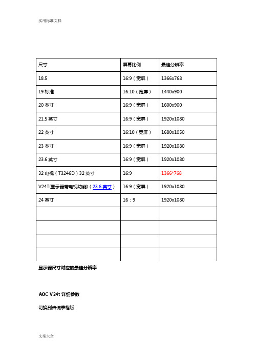
显示器尺寸对应的最佳分辨率AOC V24t详细参数切换到传统表格版基本参数显示参数面板控制接口外观设计其它显示器附件保修信息基本参数•产品定位:娱乐影音•屏幕尺寸:23.6英寸•屏幕比例:16:9(宽屏)•最大分辨率:1920x1080 •最佳分辨率:1920x1080•高清标准:1080p(全高清)•面板类型:TN•背光类型:CCFL背光•动态对比度:60000:1•黑白响应时间:5ms显示参数•点距:0.2715mm•亮度:300cd/㎡•可视面积:521.28×293.22mm •可视角度:170/160°•显示颜色:16.7M•扫描频率:水平:30-80KHz垂直:55-75Hz•带宽:148.5MHz 面板控制•控制方式:按键•语言菜单:英文,德语,法语,意大利语,西班牙语,俄语,葡萄牙语,土耳其语,简体中文接口•视频接口:D-Sub(VGA),HDMI,色差,S端子,复合信号CVBS •其它接口:TV,音频输出外观设计•机身颜色:黑色烤漆,银色底座•外观设计:超薄设计,最薄处2.5cm•产品尺寸:595.4×483.54×220.13mm(包含底座)668×565×117mm(包装)•产品重量:5.5kg(净重)7.5kg(毛重)•底座功能:倾斜•音箱:内置音箱(2×2.5W)•壁挂:100×100mm其它•电视功能:支持电视功能•HDCP:支持HDCP•电源性能:90~240V交流, 50/60Hz External Adapter•消耗功率:最大:60W待机:1W•安规认证:CCC, CB, CE, GOST,EPA •其它性能:仰角:-3-10度•其它特点:Eco Mode 5种亮度情景模式获得EPEAT金奖•上市时间:2009年06月显示器附件•包装清单:显示器主机 x1 底座 x1电源线 x1信号线 x1保修卡 x1电子光盘说明书 x1保修信息•保修政策:全国联保,享受三包服务•质保时间:3年•质保备注:整机1月内包换,2年免费上门,3年免费全保•客服电话:400-887-8007•电话备注:8:00-22:00•详细内容:在中国大陆(不包括香港、澳门特别政区)购买并在大陆地区使用的显示器,出现保修范围内的硬件故障时,凭显示器保修证正本和购机发票到“冠捷国内维修站一览表”中的任何一个维修站均可享受1个月包换,2年在规定的城市地区免费上门维修服务,3年免费保修(包含CRT及LCD面板)的123保修服务。
PRODUCT SPECIFICATIONCustomer Name (客户名称):Customer P/N (客户料号):P /N (产品料号):Date(日期):2017-1-4EDIT (制作)CHECKED (审核)APPROVED (批准)覃艳芳潘丽霞杨少拉东楼Customer Approval 客户批准□Approved 承认□Reject 拒绝Comment 意见:Approved by (确认人):XH10492A-GDA-A1History of Version变更记录Date日期Ver.版Description描述Page页码Design by变更人XH10453A-GDA-A1基础上2016-08-30A0在10LLL更改盖板外形NOTICE:The content of this specification is subject to change without further notice.assumes no responsibility concerning the accuracy,adequacy,or completeness of this specification.makes no commitment to update,or to keep current the information and material contained in this specification.Such information and material may change to conform to each confirmed order.In no event shall be made responsible for any claims attributed to errors,omissions,or other inaccuracies in the information or material contained inthis specification.shall not be liable for direct,indirect,special incidental,or consequentialdamages arising from the use of such information or material.The software (if any)described in this specification is furnished under a license or nondisclosure agreement,and may be used or copied only in accordance with the terms of such agreement.products are not intended for use in life support appliances,devices,ore of product in such applications is not supported and is prohibited.NOPARTOFTHISSPECIFICATIONMAYBEREPRODUCEDORTRANSMITTED IN ANY FORM OR BY ANY MEANS WITHOUT THE EXPRESSEDWRITTEN PERMISSION OF WGJ.XuhongXuhongXuhongXuhong Xuhong XuhongContents目录1.General Specification产品规格2.Optical Characteristics光学参数3.Reliability信赖性4.Touch panel description触摸屏功能描述4.1touch panel drawing外形图4.2Block diagram功能结构图4.3Touch panel pin assignment引脚定义5.Appearance Inspection外观检验5.1External appearance examination standard外观检验标准6.Notice注意事项6.1Notice常规注意事项6.2Other instructions其他说明6.3Suggest建议Appendix附件工程图1.General Specification产品规格Item项目C O N TE N T S内容Unit单位Outline Dimension外形尺寸224.00*174.40mmActive Area(W*L)动作区212.20*159.40mmView Area可视区211.20*158.40(10.4inch)mm TOP ITO Glass thickness ITO厚度0.70mmCoverlens thickness玻璃厚度 2.00mm Total总厚度 2.90mmTouch IC触摸IC ILI2301+M2V--Number of touchpoint触点数量10点points Number of button按键数量---Interface Type接口方式USB-Operation Temperature工作温度-20℃~70℃℃Storage Temperature储存条件温度23±3℃;湿度40%~70%RH(装机前)仓储不能超过6个月。
东莞市旭枫电子科技有限公司Dongguan Xufeng Electronic Technology Co.,Ltd 客戶名稱:No. 承認書SPECIFICATION FOR APPROVAL Description:交流安規圓板陶瓷電容器CERAMIC DISC CAPACITORS SAFETY RECOGNIZEDXYCC SERIES X1:400VAC,Y1:400VACYour Part No. Your Model No. Maker Part No. Manufacturer: Approved By Date:Y1安规电容:Y1102K400V Y5P::::广东省東莞市橋頭鎮朗厦村华厦一環路22号Tel:86(769)-86290585Fax:86(769)-86290585貴公司承認欄Approval By核准Approval審核Check經辦PreparedSPECIFIC ATION SHEETCN12B102KL02NDESCRIPTION:1000PF﹢10%~-10%Y5P CLASS X1,Y1ELECRIPTICAL SPECIFICATIONCAPACITANCE:1000PF+10%~-10%AT1KHZ1.0VrmsWORKING VOLTAGE:X1:440V Y1:400V ACTEMPERATURE COEFFICIENT:Y5P1.LOWTEMPERATUREREQUIREMENT:﹣25℃2.HIGHTEMPERATURE REQUIREMENT:﹢85℃3.MAX.CAPACITANCE CHANGE OVERTEMPERATURE RANGE:﹢10%~-10%OPERATING TEMPERATURE:-25℃~﹢125℃PRODUCT SPECIFIC ATION:DIAMETER(D):9mm MAX THICKNESS(T):3.5--5.5mm MAX. LEAD SPACING(F):10.0﹢0.5/-0.5mm LEAD SIZE(d):0.6﹢0.1/-0.1mm LEAD LENGTH(L):25.0+0.5/-0.5mm LEAD STYLE:STraight DISSPATION FACTOR:2.5%MAX.INSOLUTLON RESISTANCE:10000M COATING:EPOXY TEST VOLTAGE:4KV AC FOR1MINUTES PACKING:BULKStandard No.UL/CSA Certificate No.E509457Rated VoltageF0WX2.E509457TUV CQCX1:400V AC Y1:400V ACIEC60384-14:2013CQC19001234621XYCC Safety Standard Recognized Ceramic Capacitor1.This specification is applied to following Safety Standard Recognized Ceramic Capacitor for Electronics Appliance.TUVX1,Y1Class baned on UL /CSAX1,Y1Class baned on FOWX2.E5094572.Approval Standard and Recognized No.3.Part No.Ex.CR09B221KY2NTypeBody T.C.Nominal Capacitance Lead Lead Lead RoHSDia.CapacitanceTolerance Style Spacin gLength X1:400V AC B:Y5P K:±10%L 0:10mm 2:25mm Min.H:HF Y1:400V ACE:Y5U M:±20%Y 7:7.5mm3:3.5±1mm N:RoHSF:Y5VK 5:5±1mmD4.Rating4.1Operating Temperature:25/125/214.2LeadStyle:Dongguan Xufeng Electronic Technology Co.,LtdMarking:pany Name Code :XYCC2.Type Designation :CR3.Nominal Capacitance:3-digit-system4.Capacitance Tolerance:Code5.Manufactured Date:AbbreviationEx.2019Ex.1(January)912(February)92::10(October)9O 11(November)9N 12(December)9DC:Made in DONG GUAN6.Approval Mark:TUV Approval Mark:UL Approval Mark:CQC Approval Mark:(On the Label)EN/UL F0WX2.E509457:X1,Y1Rated Voltage Mark:400V ~,400V ~XYCC Safety Standard Recognized Ceramic Capacitor :Performance“room condition”temperature :20~35℃,humidity:45~75%,atmospheric pressure 86~106kPa.No.Item SpecificationTest Condition1Dielectric StrengthBetween lead wiresNo failureThe capacitors shall not be damage when AC2600V(for Y2Class)and AC4000V (for Y1Class)are applied between the lead wires for 60sec.(charge/discharge current <50mA)Body insulationNo failureFirst the terminals of the capacitor shall be connected together.Then a metal foil shall be closely wrapped around the body of the capacitor distance of about 3to 4mm from each terminal.Then the capacitor shall be inserted into a container filled with metal balls of about 1mm diameter.Finally AC2600V is applied for 60sec.between the capacitor lead wires and metal balls.(charge/discharge current ≦50mA)2Insulation Resistance (I.R.)10000M ΩminThe insulation resistance shall be measured with500±50VDC with 60±5sec of charging.3CapacitanceWithin specified tolerance.Char Frequency Voltage NPO/SL 1MHz ±20%5.0Vrms MaxY5P/Y5U/Y5V 1KHz ±20%The measurement at reference temperature 25∘C 4Dissipation Factor(D.F.)Char.Specified The Capacitance shall be measured At 25℃with 1±0.1KHZ for X7R&Y5P,with 1±0.1MHZ for COG and 5Vrms max.NPO/SL Q ≧300Y5PD.F ≦2.5%Y5U/Y5V D.F ≦5.0%5Temperature CharacteristicChar.Cap.Change The Capacitance measurement shall be made at each stepspecified in Table.Pre-treatment:Capacitor shall be stored at max.temperature for 1hour.Then placed at room condition for (※)24±2hours before measurements.NPO Within ±60ppm SL +350~1000%Y5P Within ±10%Y5U -56%/+22%Y5V -82%/+22%6Robustness ofTerminationTensileLead wire shall not cut off Capacitor shall not be broken.With the termination in its normal position the specimen is held by its body in such a manner that the axis of the termination isvertical the tensile force of 10N shall be applied to thetermination in the direction of its axis and acting in a direction away from the body of the specimen.Bending Lead wire shall not cut off Capacitor shall not be broken.With the termination in its normal position the specimen is held by its body in such a manner that the axis of the termination isvertical :a mass applying a force of 5N is then suspended from the end of the termination.The body of the specimen is then inclined within a period of 2to 3sec.,through an angle of a approximately 90in the vertical plane and then returned to its initial position over the same period of time;this operation constitutes one bend.One bend immediately followed by a second bend in the opposite direction.StepTemperature P.F1+25±2℃2Min.operation temp.3+25±2℃4Max.operation temp.5+25±2℃1sec)by UL1414and CSA E384-14previous safety standards.(UL1414is deleted in this SPEC11Flame Test The capacitor flame discontinue asfollows.The capacitor shall be subjected to applied for 15sec.And thenremoved for 15sec,until 5cycle.(Unit:mm)12Active FlammabilityThe cheese-cloth shall not be on fireThe specimens shall be individually wrapped in at least one but more than two complete layers of cheese-cloth The specimens shall be subjected to 20discharges.The interval betweensuccessive discharges shall be 5sec.The Uac shall be maintained for 2min.after the last discharge.C1,2:1μF ±10%C3:0.33μF ±5%10KV Ct :3μF ±5%10KV Cx :CapacitorL1-10:1.5mH ±20%16A Rod core choke R :100Ω±2%,Uac :Ur ±5%Ur :Rated working voltage F :Fuse,Rated 10AUt :Voltage applied to CtCycleTime1to 430sec.max.560sec.Max.。