pumplinx软件资料集合续(一)
- 格式:pdf
- 大小:520.22 KB
- 文档页数:10

Q:PumpLinx安装过程大概需要多久?需要安装其他组件吗?A:PumpLinx安装相对比较容易,“一键式”的安装能够确保软件安装过程不会出错,对于一般配置的电脑,也只需要几分钟便可完成安装。
对于服务器端,还需要安装License服务器,而对于客户端,只安装软件即可。
Q:PumpLinx对电脑操作系统有何要求?是否兼容64位机?A:PumpLinx对操作系统的兼容性较好,Windows 2000/XP/Vista/Win 7均可安装,Linux操作系统也可以安装。
另外,PumpLinx可以在64位机上安装使用,安装时注意选择64位专用的安装程序即可。
Q:如何获取软件使用许可?A:软件安装好之后,在获取有效的License之前是无法正常使用的,用户需要将打开软件时弹出的错误信息提示框中的“Local Hardware ID”号提供给海基,并由海基向Simerics公司提供申请,一般情况下,只需1-3个工作日,便可将有效的License提供给用户。
Q:申请到的License如何设置?A:License分为固定式和浮动式两种,对于浮动式License,首先需要在服务器端安装“License Server Installation”,安装完成之后,该程序将在“开始-所有程序-Simerics”中产生四个选项,将申请到的floating license拷贝到license server安装目录下,如C:\Program files\Simerics,并将license文本第一行中的localhost 替换为服务器的计算机名,然后在“开始-所有程序-Simerics”中运行Start License Server。
服务器启动后,在客户端机器上的Simerics安装路径下新建license.txt 文件,并将floating license中的第一行语句拷贝至该文件中,并将localhost替换为服务器计算机名,保存后即可启动软件。

史上最全面的PLC解密软件下载集合,绝对免费下载共享!软件名称软件说明论坛下载本站下载西门子S7-200 PLC 解密软件可解S7-200PLC密码(212、214、215、216、222、224、224XP、226、226XM)直接用PC/PPI编程电缆读出密码,可解系统密码和子程序密码。
解密只需1秒。
可解除CN以外的和版本号2.0以下的全部型号《查看详细的软件适用说明》《看一下200的解密说明》S7-200 POU 密码破解软件用于破解西门子S7-200PLC的程序上载后加锁的子程序的开锁,开锁后便可以显示和编辑程序块。
在线观看本pou密码破解的视频教程请点击这里、下载观看请在此点击下载。
S7-200项目密码破解简化版本站最新开发,一个可以让西门子200项目文件密码形同虚设的软件,此功能已集成到解密软件中S7-300PLC解密软件软件西门子S7-300系列PLC解密软件,直接读出MMC卡的密码,无次数限制无限制复制版,如果您要破解无卡的S7-300型号(如CPU314)和S7-400的型号密码请联系我点击查看详细的使用说明欧姆龙真正运行直读版解密PLC解密网强势推出-欧姆龙PLC解密软件,可直读CQM1H,C200H,C200HS, C1000H, C2000H, CPM1, CPM2*-S*, CQM1、CPM1A、CPM2A等系列,可解C系列四位密码,是真正意义上的运行直读版,无需停机直接就可以读出密码。
非穷举法解密,也不是早期的删除后又写入的假直读软件。
OMRON任务密码直读软件可以通过PLC的串口直接读取任务密码,超强联机性能,对最新版CJ2M CS1G CJ1M CP1H CP1L有效。
欧姆龙CP1E加密可以对欧姆龙CP1E CP1L CP1H 进行超级加密保护,非官方加密,有效保护您的程序现今还无法破解。
松下PLC解密可解FP0、FP1、FP2、FP2SH、FP3、FPM、FPC、FP5、FP10、FP10S、FP10SH系列密码FPX和FPG 不可解松下触摸屏解密可解现有的松下触摸屏的所有型号密码三菱PLC解可解FX0 、FX0S 、FX0N 、FX1N 、FX1S 、FX2 、FX2N、FX2NC、A系列和FX3U的一段密密软件下载码,关于Q系列的请单独到这里下载三菱触摸屏解密三菱F930、F940、A900、F900触摸屏解密软件富士PLC解密可解富士NB、NJ、NS、SPB等N系列PLC密码,无次数限制富士触摸屏解密可解现有的富士触摸屏的所有型号永宏PLC解密可解永宏FB、FBA、FBN、FBE、包括ID密码,FBS系列可解版本号为4.52以下型号,最新的无法破解,严禁使用,损坏自负!!LGK系列解密软件下载真正的可以破解K120S.K120SE最新版本V2.9系列CPU密码,独家免费推出,LG K系列PLC常用型号的解密请到这里下载。
培训教材第一天培训内容——熟悉硬件和软件一、熟悉各硬件请查看各模块的外形,通讯模块,I/O模块,运动控制模块,处理器模块。
框架式设计可靠,安装容易,无需工具。
端子可取下,接线方便,更换快速。
将DEMO上电,插入ENBT/ENET, CNB通讯模块以及I/O模块(可以先不插入CPU)。
体会模块的带电热插拔特性。
安装方便。
二、认识RSLinx软件1、什么是RSLinx?RSLinx软件是工业通讯的枢纽。
它为所有的AB网络提供了完整的驱动程序。
通过RSLinx软件,用户可以通过一个窗口查看所有活动网络,也可以通过一个或多个通讯接口同时运行任何所支持的应用程序的组合。
RSLinx提供最快速的OPC、DDE和Custom C/C++的接口。
RSLinx还可以为用户提供多个网络、本地工作站和DDE/OPC性能诊断工具,便于进行系统维护和故障排错。
RSLinx Gateway驱动程序能够完美地支持TCP/IP客户与AB PLC控制器的连接,它也支持与远程OPC进行通讯。
2、使用RSLinx软件进行通讯1)打开RSLinx,点击或2)在工具条上点击选择Ethernet Devices(其它的驱动程序简单介绍), 按下Add New 键单击OK.3)增加以太网设备单击OK.4)单击Close5)检查击计算机的IP设定。
确认为:192.168.1.XXX.6)单击。
可以看到,我们不需要CPU,就可以通讯。
减少CPU负荷,提高通讯效率。
保证实时性,可重复性。
7)展开树形。
所有模块信息可以自动浏览得到。
方便维护,调试。
8)插入CPU模块。
无槽位限制,可扩展性好。
例如:当需要多个以太网时,不用放在前几个槽位。
在03槽,1756- L55上点击Device Properties.显示CPU 信息。
点击Configure New DDE/OPC Topic,组态DDE/OPC主题(如果您使用的RSLinx为2.40以上的版本,那么RSLinx会自动创建DDE/OPC主题)3、使用DF1驱动程序与处理器进行通讯1)打开RSLinx,点击或2)在工具条上点击3)选择RS-232 DF1 devices, 按下Add New 。
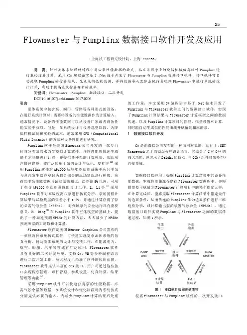
设 计 与 研 究25引言流体系统中包含泵、阀门、管路等各种形式的设备,在进行系统计算时,需要将设备的性能数据作为计算输入。
通常情况下,设备的性能数据可以从设备厂家或者设备性能实验中获取。
但是,在系统设计与设备选型阶段,为降低样机试制和实验的成本,通常采用CFD(Computational Fluid Dynamic)的方法对设备性能进行研究。
Pumplinx 软件是美国Simerics 公司开发的一款专门针对各类泵的水力学模拟计算软件。
该软件能够快速生成笛卡尔网格进行计算,并提供各种泵的计算模块,帮助用户快速建模,被广泛应用于泵的设计与优化。
夏栓等[1]采用Pumplinx 软件对AP1000反应堆冷却剂系统中两台主泵与蒸汽发生器腔室封头耦合部分的流场情况进行模拟,获得的主泵性能数据与试验结果相比,误差在5%以内,可用于指导AP1000冷却剂系统的设计工作。
L. Li 等[2]采用Pumplinx 软件对双吸程离心泵进行仿真分析,泵的扬程计算结果与试验数据的误差小于1.8%,并通过计算获得了泵的必需气蚀余量(NPSHr),对保障泵的安全运行具有重要意义。
H. Ding [3]在Pumplinx 软件空化模型的基础上,提出了一种加速预测NPSHr 的计算方法,大大减少了NPSHr 预测所需的工况数和计算量。
Flowmaster 软件是美国Mentor Graphics 公司发布的一款热流体系统仿真软件,可快速实现复杂流体系统的仿真分析,辅助流体系统的设计与校核工作,在能源电力、航空、船舶、汽车等领域有广泛应用。
Flowmaster 软件具有良好的二次开发环境,支持C#、VB 等多种编程语言进行二次开发工作,极大程度上拓展了软件的应用范围。
Flowmaster 软件提供丰富的COM 接口,用户可通过这些接口实现程序管理、项目管理、参数设置、仿真计算、结果管理等功能[4]。
采用Pumplinx 软件可以快速获得泵的性能数据、必需气蚀余量等数据,在系统设计和优化阶段可为系统仿真分析提供必要的输入。
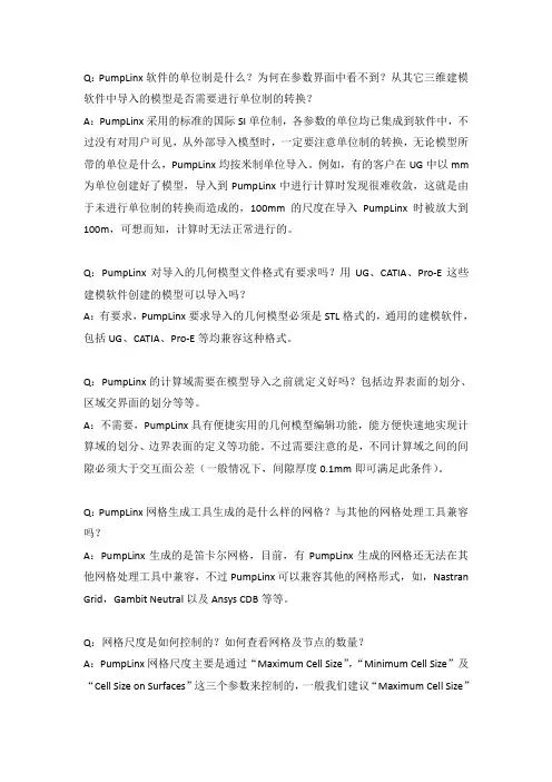
Q:PumpLinx软件的单位制是什么?为何在参数界面中看不到?从其它三维建模软件中导入的模型是否需要进行单位制的转换?A:PumpLinx采用的标准的国际SI单位制,各参数的单位均已集成到软件中,不过没有对用户可见,从外部导入模型时,一定要注意单位制的转换,无论模型所带的单位是什么,PumpLinx均按米制单位导入。
例如,有的客户在UG中以mm 为单位创建好了模型,导入到PumpLinx中进行计算时发现很难收敛,这就是由于未进行单位制的转换而造成的,100mm的尺度在导入PumpLinx时被放大到100m,可想而知,计算时无法正常进行的。
Q:PumpLinx对导入的几何模型文件格式有要求吗?用UG、CATIA、Pro-E这些建模软件创建的模型可以导入吗?A:有要求,PumpLinx要求导入的几何模型必须是STL格式的,通用的建模软件,包括UG、CATIA、Pro-E等均兼容这种格式。
Q:PumpLinx的计算域需要在模型导入之前就定义好吗?包括边界表面的划分、区域交界面的划分等等。
A:不需要,PumpLinx具有便捷实用的几何模型编辑功能,能方便快速地实现计算域的划分、边界表面的定义等功能。
不过需要注意的是,不同计算域之间的间隙必须大于交互面公差(一般情况下,间隙厚度0.1mm即可满足此条件)。
Q:PumpLinx网格生成工具生成的是什么样的网格?与其他的网格处理工具兼容吗?A:PumpLinx生成的是笛卡尔网格,目前,有PumpLinx生成的网格还无法在其他网格处理工具中兼容,不过PumpLinx可以兼容其他的网格形式,如,Nastran Grid,Gambit Neutral以及Ansys CDB等等。
Q:网格尺度是如何控制的?如何查看网格及节点的数量?A:PumpLinx网格尺度主要是通过“Maximum Cell Size”,“Minimum Cell Size”及“Cell Size on Surfaces”这三个参数来控制的,一般我们建议“Maximum Cell Size”与“Cell Size on Surfaces”的比值控制在2:1到4:1之间。
RS--Linx软件应用(一)一、RSLinx通信软件概述RSLinx系列软件是用于AB公司可编程控制器的*****器软件,为AB公司的PLC处理器与罗克韦尔自动化以及其它公司的(如微软)的许多软件产品提供了通信连接。
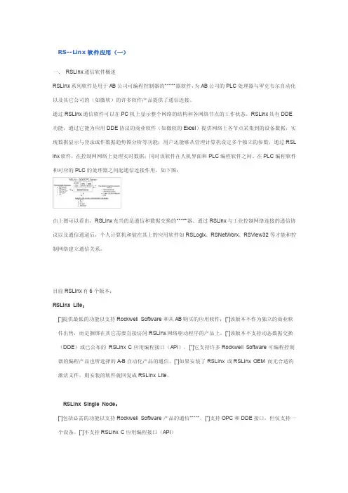
通过RSLinx通信软件可以在PC机上显示整个网络的结构和各网络节点的工作状态。
RSLinx具有DDE 功能,通过它能为应用DDE协议的商业软件(如微软的Excel)提供网络上各节点采集到的设备数据,实现数据显示与登录或作数据趋势图分析等功能;用户还能够从管理计算机设定多个独立的参数,通过RSL inx软件,在控制网网络上处理实时数据;同时该软件在人机界面和PLC编程软件之间、在PLC编程软件和对应的PLC的处理器之间起通信连接作用。
如下图:由上图可以看出,RSLinx充当的是通信和数据交换的*****器。
通过RSLinx与工业控制网络连接的通信协议以及通信通道后,个人计算机和装在其上的应用软件如RSLogix、RSNetWorx、RSView32等才能和控制网络建立通信关系。
目前RSLinx有6个版本:RSLinx Lite:[*]提供最低的功能以支持Rockwell Software和从AB购买的应用软件;[*]该版本不作为独立的商业软件出售,而是捆绑在其它需要直接访问RSLinx网络驱动程序的产品上。
[*]该版本不支持动态数据交换(DDE)或已公布的RSLinx C应用编程接口(API)。
[*]它支持许多Rockwell Software可编程控制器的编程产品也所选择的A-B自动化产品的通信。
[*]如果安装了RSLinx 或RSLinx OEM 而无合适的激活文件,则安装的软件就回复成RSLinx Lite。
RSLinx Single Node:[*]包括必需的功能以支持Rockwell Software产品的通信*****。
[*]支持OPC和DDE接口,但仅支持一个设备。
[*]不支持RSLinx C应用编程接口(API)RSLINX OEM:[*]RSLinx OEM包括必需的功能以便支持与所有Rockwell Software可编程控制器与MMI产品的通信[*]它具有RSLinx Lite所有的功能,加上限于Rockwell Software产品的AdvanceDDE,它还支持用户使用RSLinx C 应用程序编程接口(API)开发的应用程序[*]该产品支持众多软件商使用RSLinx C SDK (S oftware Development Kit)开发的应用程序。


Proceedings of FEDSM20122012 ASME Fluids Engineering Division Summer MeetingJuly 8-12, 2012, Puerto Rico, USAFEDSM2012-72282 A PRACTICAL APPROACH TO SPEED UP NPSHR PREDICTION OF CENTRIFUGALPUMPS USING CFD CAVITATION MODEL (EXCERPTS)H. DingSimerics Inc. Bellevue, Washington, USA hd@F.C. Visser Flowserve, Pump Division Etten-Leur, The Netherlands fvisser@Y. JiangSimerics Inc. Bellevue, Washington, USA yj@ABSTRACTThis paper presents an innovative NPSHr prediction procedure. Derived through analyzing the definition of NPSHr and the characteristics of pump head vs. NPSH curve (i.e. head drop curve), this procedure can significantly reduce the number of simulations needed in NPSHr prediction. For the majority of cases, NPSHr can be predicted with reasonable accuracy for one flow rate in as little as three simulation runs. This procedure is also very robust since it can avoid running simulations under severe cavitation conditions. Therefore simulation convergence is improved and simulation time is reduced for each simulation step.In the paper, the methodology of the proposed approach is derived and explained. The complete procedure with suggested strategies is laid out in detail. Then the procedure is demonstrated against an industrial pump case. NPSHr prediction results are compared with experimental data. Important factors which can affect NPSHr prediction are also indentified and discussed.Key words: NPSH, Cavitation, Numerical Simulation, CFD. NOMENCLATURE1, 2, ..n, .. The nth stepa, b, c Coefficients of the quadratic equationC1Turbulence model constantC2Turbulence model constantC c Cavitation model constantC e Cavitation model constant Cμ Turbulence model constantD f Diffusivity of vapor mass fraction DH Dynamic head (Pa)f Body force (N)f v Vapor mass fractionf g Non-condensable gas mass fractionG t Turbulent generation termH Pressure head (m or Pa)k Turbulence kinetic energyL LengthM Mass flow rate (Kg/s)m Coefficient of the parabolic equation N Rotation speed (RPM)n Surface normalNCG Non-condensable gasNPSH Net Positive Suction Head (m) NPSHr Net Positive Suction Head required NPSH3NPSH with 3% head dropPT Total pressure (Pa)PS Static pressure (Pa)p Pressure (Pa)Q Flow rate (m3/h)R c Vapor condensation rateR e Vapor generation rateRPM Revolution per minutet TimeS'ij Strain tensorU Initial velocityu Velocity component (m/s)u'Component of v'v Velocity vectorv'Turbulent fluctuation velocitySubscriptin Inletout OutletGreek Symbolsε Turbulence dissipationμ Fluid viscosity (Pa-s)μt Turbulent viscosity (Pa-s)ρ Fluid density (kg/m3)ρg Gas density (kg/m3)ρl Liquid density (kg/m3)ρv Vapor density (kg/m3)σSurface of control volumeσk Turbulence model constantσl Surface tensionσεTurbulence model constantσf Turbulent Schmidt numberτ Stress tensorΩ Control volumeINTRODUCTIONNet Positive Suction Head, NPSH, is defined as the total fluid head at the inlet of a pump. The formula to calculate NPSH is:NPSH =PT−Pρg, (1) in which PT is inlet total pressure, P v is vapor pressure of the fluid, ρ is density, and g is acceleration of gravity. Net Positive Suction Head required, NPSHr, is a very important parameter for centrifugal pumps (Schiavello and Visser, 2009). It is also referred to as NPSH3 per API 610, 11th ed. It determines when a pump will operate at three percent loss of head due to cavitation. This NPSH3is the commonly used criterion for NPSHr to pinpoint the limit for acceptable operation. At 3% head drop, a centrifugal pump will experience significant cavitation.Apart from cavitation visualization model testing, Computational Fluid Dynamics (CFD) simulation with cavitation models is the only alternative tool available to the engineer to predict and analyze pump NPSH behavior in detail. Today’s CFD software with cavitation models has been commonly used in pump design and analysis. Satisfactory results have been obtained regarding hydraulic performance and cavitation patterns for many pump applications (Ding et al. 2011, Bakir et al. 2004, Dupont and Okamura 2003, Visser 2001). For centrifugal pump simulation, there are two approaches: the transient method and the Multi-Reference Frame (MRF) method. MRF, which uses a steady state approach with a rotating frame to account for pump rotation, is widely used to predict pump hydraulic head and efficiency. The MRF method can save a significant amount of simulation time, and can obtain reasonable results for some pump applications. However there are many cases for which transient simulations are necessary to get satisfactory accuracy even for performance prediction. It is often observed that MRF tends to over-predict the asymmetry of cavitation bubbles because it assumes a fixed relative position between the impeller and the volute/diffuser. This discrepancy typically introduces errors in NPSHr prediction since NPSHr is very sensitive to cavitation bubble distribution.When there are big cavitation regions in the flow field, the simulation usually takes much longer to reach a balanced solution. This is mainly due to the time needed in cavitation bubble development. For example, in a real pump operation, a big cavitation bubble may need ten’s of impeller revolutions to reach a balanced size/position. It should, accordingly, take a similar amount of time for the CFD simulation to reach a balanced solution if all the physics are modeled accurately.As with physical testing, in a traditional CFD NPSHr prediction process multiple steps are needed to gradually approach the 3% head drop point for each flow rate. For each of these steps in the process, one needs to run a CFD simulation. Another common drawback is that, during this process, simulations can easily be dragged into severe cavitation condition. Under such severe cavitation condition, simulations can take a long time to converge – even for the most efficient cavitation model. As a result, the whole process can be extremely time- consuming, especially when transient simulations are necessary in order to obtain sufficient accuracy. Because of the excessive simulation cost, CFD prediction of NPSHr is not routinely used in industry to analyze and improve pump design.This paper presents an original approach using CFD to predict pump NPSHr. The new approach is faster and more robust compared to traditional approaches, and therefore could potentially improve the usability of CFD as a prediction tool for pump NPSHr studies. The proposed method will be introduced and discussed in detail in the next section. Later it will be applied to predict NPSHr of an industrial centrifugal pump. The prediction procedure will be demonstrated and the results will be compared with experimental data. The CFD simulation results presented in this paper were generated from a commercial CFD package, PumpLinx. However the proposed procedure itself can be used with any CFD software package assuming it can accurately model cavitation.(NOTE: The sections on the procedure itself have been edited out. For detailed information on the procedure, contact ASME for a copy of the complete paper.)PUMP MODELAn industrial centrifugal pump was used to demonstrate the NPSHr prediction procedure. It is a single stage, end suction centrifugal pump. This pump has a five blade shrouded impeller and a diffuser with four guide vanes operating at 1470 rpm. The working fluid is water. Figure 7 shows impeller and diffuser hardware.Figure 7: Pump hardwareFigure 8: The test rigThe pump was tested in a closed loop test rig. The test was done as part of an upgrade to improve NPSH3. The water used in the test was not deaerated. Figure 8 shows the test rig with the pump mounted.Figure 9: Pump fluid domainAll the important flow passengers including balance holes and seal leakages are modeled in CFD as fluid domains (Figure 9 and figure 10).About 0.75 million cells were used in the CFD model. Figure 11 shows the mesh distribution on a vertical cutting plane.The fluid properties used in simulation are listed in table 1.A series of simulations for pump head vs. flow rate under normal operating condition was carried out using both steady state MRF and transient approaches. In those simulations, fluids were treated as incompressible. Figure 12 shows the comparison of simulation results and test results.Figure 10: Fluid domain with seal leakage gaps andbalance holesFrom the plot it can be seen that apparently this pump has strong transient effects. The MRF simulations could not provide satisfactory results. Therefore the following NPSHr simulations were all done using the transient approach.Figure 11: Mesh in a cutting plane The first NPSHr prediction is for the cases with 682.5 m3/h flow rate. Table 2 records detailed information of a sequence of simulations. Since the normal head of this flow rate is already known from the previous performance simulation, the Step 0 simulation is not needed. A 2.3E-5 mass fraction of air (corresponding to about 2% volume fraction under room condition) was used for these simulations.Figure 12: Pump performance predictionTable 2: NPSHr prediction steps for 682.2 m3/h flow with2% airFrom the results, it shows that with only 3 simulation steps, the NPSHr prediction has already reached the 3.3% head drop point which is close enough for most engineering purposes. Please note there is a small difference (~2%) between the 100% head from step 1 and the incompressible transient simulation results plotted in Figure 10 due to the different approaches used in the two simulations, mainly incompressible vs. cavitation model.To compare with the traditional approach, a transient simulation with a cavitation model using 3.4 meter as the inlet total pressure, and 682.5m3/h as the outlet flow rate was performed. The result shows a 3.6% head drop. This confirms that the proposed approach generates final NPSHr results similar to the traditional approach.Figures 13 –15 show the cavitation bubbles at the z=0 cutting plane for simulation step 1, 2, and 3. All three plots show color maps of the total gas (vapor and air) volume fraction ranging from 0 to 100%, where blue corresponds to 0% gas and magenta indicates 100% gas. No cavitation is observed in that plane at step 1. As expected, moderate cavitation regions show up at step 2 and step 3. Cavitation bubble shrinks when the NPSH increases from step 2 to step 3.Figure 13: Cavitation pattern at step 1 The cavitation pattern from a steady state MRF simulation using 3.4 meter as the inlet total pressure and 682.5m3/h as the outlet flow rate is plotted in Figure 16. Compared with Figure 13, the MRF result shows a very asymmetrical cavitation pattern.Figure 14: Cavitation pattern at step 2 NPSHr predictions for four additional flow rates, 79.6, 249.7, 398.8, and 899.4m3/h, have been performed with the same approach and a 2% air content. Figure 17 plots the head drop curves at a 682.5 m3/h flow rate. Figure 18 plots the NPSHr vs. flow rate curve. Both simulation results and experimental data are plot together for comparison.Figure 15: Cavitation pattern at step 3 The two plots shows that the simulation results with 2% air contents consistently underpredict the NPSH compared to the experimental results for the same flow rate and pump head. Since this pump was tested on a closed loop without deaeration, there could be more than 2% air in the water. It is well known that extra air can degrade pump NPSHr characteristics (Budris and Mayleben, 1998). Additional simulations with more air contents were carried out to investigate effects of the air contents on pump NPSHr performance for the flow rate of 682.5m3/h. The results from those additional simulations are also plotted in Figure 17 and Figure 18. Results show that with 8% of air (9.2E-5 mass fraction), the CFD predicted NPSHr is much closer to the experiment measurement. More investigations are needed to better understand the NPSHr behavior of this pump under the influence of different air contents. However this is beyond the scope of this paper.Figure 16: Cavitation pattern from MRF simulationFigure 17: The head drop curve at 682.5 m3/h flow rate CONCLUSIONSAn innovative NPSHr prediction approach is presented in this paper. The principal of the method is fully explained. The complete procedure is laid out in detail. Important issues pertaining to the new method are identified with suggested solution strategies. Compared with the traditional approach, the proposed approach introduces a very predictable and controllable simulation procedure with significant savings in the number of simulation runs and simulation time. The new method is applied to the NPSHr study of an industrial centrifugal pump. The NPSHr is predicted with reasonable accuracy in as little as three simulations for one flow rate. With demonstrated efficiency and robustness against real engineer application, the new method could be used effectively for pump NPSH performance study.Figure 18: NPSHr at different flow rateREFERENCESBudris, A.R., and Mayleben, P.A. 1998 "Effects of entrainedair, NPSH margin, and suction piping on cavitation in centrifugal pumps", Proceedings of the Fifteenth International Pump Users Symposium, Turbomachinery Laboratory, Texas A&M University, College Station, Texas, USA, pp. 99-108.Ding, H., Visser, F.C., Jiang, Y . and Furmanczyk, M. 2011“Demons tration and validation of a 3D CFD simulation tool predicting pump performance and cavitation for industrial applications", J. Fluids Eng. – Trans ASME, 133(1), 011101.Dupont, P. and Okamura, T. 2003, “Cavitating flow calculationsin industry,” Int. J. Rotating Mach., 9, pp. 163-170.Jiang, Y ., Zhang, D., Furmanczyk, M., Lowry, S. and Perng, C.2008, “A three -dimensional design tool for crescent oil pumps,” SAE World Congress, April 14-17, Detroit, MI, Paper No. SAE-2008-01-0003.Launder, B.E. and Spalding, D.B. 1974 “The numericalcomputation of turbulent flows,” Comput. Methods Appl. Mech. Eng., 3, pp. 269-289.Schiavello, B. and Visser, F.C. 2009 “Pump cavitation –various NPSHR criteria, NPSHA margins, and impeller life expectancy,” Proceedings of the Twenty-fifth International Pump Users Symposium, Turbomachinery Laboratory, TexasA&M University, College Station, Texas, USA, pp. 113-144.Singhal, A.K., Athavale, M.M., Li, H.Y . and Jiang, Y . 2002“Mathematical basis and validation of the full c avitation model", J. Fluids Eng. – Trans ASME, 124(3), pp. 617-624.Visser, F.C. 2001 “Some user experience demonstrating the useof CFX-TASCflow computational fluid dynamics for cavitation inception (NPSH) analysis and head performance prediction of centrifugal pump impellers,” ASME Fluids Engineering Division Summer Meeting, May 29 – June 1, New Orleans, LA, Paper No. FEDSM2001-18087.Wood, D.W., Hart, R.J, and Marra, E. 1998 “Applicationguidelines for pumping liquids that have a large dissolved gas cont ent,” Proceedings of the Fifteenth International Pump Users Symposium, Turbomachinery Laboratory, Texas A&M University, College Station, Texas, USA, pp. 91-98.。
这是一篇2011年七月Best PumpWorks在Pumps&Systems Magazine上获得二等奖的文章。
Best PumpWorks是世界上最大的改制离心泵的供应商之一,它们的泵遍布世界各地。
为了优化泵,减少泵的设计周期,Best PumpWorks已经结合了最先进的模拟工具来进行设计工作,使用模拟能够在虚拟世界里帮助设计和预测从而优化泵的的性能,Best PumpWorks 已经能够在更短的时间里设计改进泵从而满足客户对泵的性能需求。
最近接触的一个客户,Best PumpWorks在最短的时间内提供一个大的单级双吸入口泵,如图1所示,然后使用测试回路来评估了系统性能。
要求这个泵在转速为1780转/分,每分钟8500加仑流量(1980.3m3/h)情况下,扬程达到792英尺(241米),主要的难点是要求提供5叶片的叶轮,但是这种情况在这种规格的泵设计里是不标准的。
正常情况下在给定了叶轮直径后,需要提供高效率和高扬程,一般是6、7片叶轮设计。
为了达到这种泵的探究设计,Trey Maxwell运用了最先进的模拟。
运用CFturbo来完成产品设计,PumpLinx来完成虚拟机的预测,从而便于提出修改。
这对于有经验的泵工程师来说是非常友好的,他们可以更好的将自己的经验与软件结合起来,从而直接快速准确地来设计优化泵。
两个软件包的初步培训是3天。
在培训中,Best PumpWorks工程师应用CFturbo创建一系列不同的叶轮,需要特别关注5个叶片的设计。
CFturbo基于输入的性能参数,使用验证的经验公式和涡轮机械设计理论来帮助完成泵各部分的设计。
设计参数包括扬程、流量、转虽然CFturbo预测性能是非常有效的,但是他们的范围还是有限的,它不能像CFD工具一样通过提供一个高逼真度的虚拟测试来预测。
因此,下一步是使用仿真软件PumpLinx,如图4括微米级别的泄露问题,在PumpLinx中,空气水蒸气的形成,膨胀,运输(空化现象)都可以模拟。
PLC编程资料、PLC编程软件随着现代工业设备自动化,越来越多的工厂设备将采用PLC、变频器、人机介面等自动化器件来控制,因此设备自动化程度越来越高。
对设备的维护人员的技术要求越来越严格。
作为一名合格的技术员,需要掌握的技能也越来越多,越来越全面性,以此来满足自动化的开展及要求,因此设备相关的资料及软件,对我们技术员来说是必需具备的,为了满足大家的要求。
经过多年的积累,整理出四种最常用的三菱、OMRON 、AB、及西门子公司的相关资料及软件,特价向大家提供,详细软件资料清单见下面。
A盘:包含:西门子新版LOGOV4.0控制器编程软件,LOGO 新版使用手册大全。
新版S7-200PLC中文版编程软件,s7_200_sim模拟软件汉化版,S7-200的中文系统手册大全。
S7-200上位机软件PC_Access_V10。
OP、TP系列中文版编程软件及编程手册大全,WINCC中文版编程手册,Protool 中文手册,西门子STEP5教程中文版〔NEW〕,PG702编程器操作手册,所有西门子公司自动化设备相关的中文资料,S7-200与S7-300的应用论文集,S7-200的应用实例〔中文注释〕,S7-400.S7-300梯形图(LAD) 中文版编程手册等。
(共650M,详细清单见A盘说明)B盘:包含:三菱FX、A、Q系列GX-Developer V7.08中文版PLC编程软件及中文使用手册。
三菱FX20GM位置控制器编程软件、三菱PLC程序调试离线仿真软件GX-Simulator6中文版、三菱PLCFX最新FXGPWINV330〔中文版〕,三菱FX系列仿真软件LTT-C简体中文版、三菱PLC可编程控制器教材、FX2N、FX2NC、FX1N、FXNS、FX0N、FX0S系列中文编程手册大全,FX随机手册及模块手册大全,FX-10P、20P编程器中文使用说明,三菱FR系列变频器使用手册大全。
(共650M,详细清单见B盘说明)C盘:包含:OMRON-SSS中文版PLC编程软件,OMRON 全系列中文版编程软件CX-P V3.2、Cx-simulator离线仿真软件,人机介面NT系列设计软件,SysWin34OMRON最新开发的智能控制器的编程仿真软件,最新CS1-CJ1-CJ1M系列PLC中文版操作手册、指令参考手册、编程手册大全、高速计数器、操位置控制、通信单元、温度控制等模块中文手册大全,CX-P中文版软件手册,OMRON PLC培训教材〔编程器SSS使用、CPMIA根底及CPMIA系统〕。