PumpLinx安装FAQ
- 格式:doc
- 大小:35.00 KB
- 文档页数:2
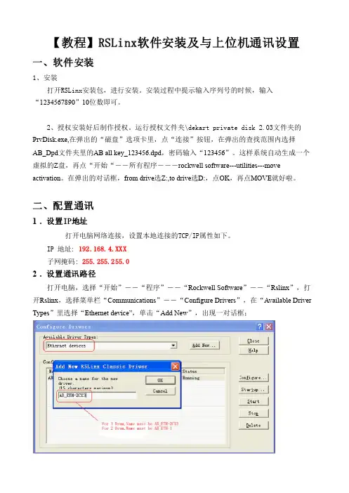
【教程】RSLinx软件安装及与上位机通讯设置一、软件安装1、安装打开RSLinx安装包,进行安装。
安装过程中提示输入序列号的时候,输入 “1234567890”10位数即可。
2、授权安装好后制作授权。
运行授权文件夹\dekart private disk 2.03文件夹的PrvDisk.exe,在弹出的“磁盘”选项卡里,点“连接”按钮,在弹出的查找范围内选择AB_Dpd文件夹里的AB all key_123456.dpd,密码输入“123456”。
这样系统自动生成一个虚拟的Z盘,再点“开始“--所有程序---rockwell softwareutilitiesmove activation。
在弹出的对话框,from drive选Z:,to drive选D:,点OK,再点MOVE就好啦。
二、配置通讯1. 设置IP地址打开电脑网络连接,设置本地连接的TCP/IP属性如下。
IP 地址: 192.168.4.XXX子网掩码: 255.255.255.02. 设置通讯路径打开电脑,选择“开始”――“程序”――“Rockwell Software”――“Rslinx”,打开Rslinx,选择菜单栏“Communications”――“Configure Drivers”,在“Available Driver Types”里选择“Ethernet device”,单击“Add New”,出现一对话框;如上图,选择合适的name(三鼓写AB_ETHZCX3,两鼓写AB_ETH1)后,单击“ok”后,出现下面的对话框:如图,将station列的0行输入正确的ip(192.168.4.200),点确定。
返回,在“Communications”――选择“RSWho”,点AB_ETHZCX3,联机的话就可以找到所有的PLC模块和DeviceNet网络上的设备。
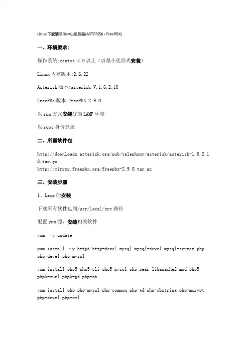
Linux下安装呼叫中心服务器(ASTERISK+FreePBX)一、环境要求:操作系统:centos 5.0以上(以最小化形式安装)Linux内核版本:2.6.22Asterisk版本:asterisk V.1.6.2.18FreePBX版本:FreePBX:2.9.0以rpm方式安装好的LAMP环境以root身份登录二、所需软件包/pub/telephony/asterisk/asterisk-1.6.2.1 8.tar.gz/freepbx-2.9.0.tar.gz三、安装步骤1、Lamp的安装下载所有软件包到/usr/local/src路径配置yum源,安装相关软件yum –y updateyum install –y httpd http-devel mysql mysql-devel mysql-server php php-devel php-mysqlyum install php5 php5-cli php5-mysql php-pear libapache2-mod-php5 php5-curl php5-gd php-dbyum install php php-mysql php-common php-gd php-mbstring php-mcrypt php-devel php-xmlyum install e2fsprogs-devel keyutils-libs-devel krb5-devel libogg libselinux-devel libsepol-devel libxml2-devel libtiff-devel gmpphp-pear php-pear-DB php-gd php-mysql php-pdo kernel-devel ncurses-devel audiofile-devel libogg-devel openssl-devel mysql-devel zlib-develperl-DateManip sendmail-cf soxyum install gcc gcc-c++ wget bison mysql-devel mysql-server php php-mysql php-pear php-pear-DB php-mbstring nano tftp-server httpd makencurses-devel libtermcap-devel sendmail sendmail-cf caching-nameserver sox newt-devel libxml2-devel libtiff-devel php-gd audiofile-develgtk2-devel subversion kernel-develyum install festival festival-devyum install ncurses-base ncurses-bin ncurses-term libncurses5 libncursesw5 libncurses5-dev libncursesw5-devyum install zlib1g zlib1g-devyum install bison bison-docyum install install libxml2 libxml2-devyum install libtiff4 libtiff4-devyum install libasound2 libgsm1 libltdl3 libpq4 libspeex1 libsqlite0 libtonezone1 libaudiofile0 libaudiofile-devyum install libnet-telnet-perl mime-construct libipc-signal-perl libmime-types-perl libproc-waitstat-perlmkdir /var/lib/mysqlchown –R mysql:mysql /var/lib/mysql/etc/init.d/httpd startchkconfig –level 35 httpd onmysql_install_dbchown –R mysql.mysql /var/lib/mysql/etc/init.d/mysqld startchkconfig –level 35 mysqld onmysqladmin –uroot password 123456 \\设置mysql密码为123456 cp /usr/share/doc/mysql-server-5.0.22/f /etc/f /etc/init.d/httpd restartvim /var/www/html/index.php测试一下:测试php连接apache : <? phpinfo(); ?>测试php连接mysql : vim /var/www/html/aaa.php<?php$link=mysql_connect("localhost","root","123456");if(!$link) echo "FAILD!";else echo "OK!";?>访问下即可。
设 计 与 研 究25引言流体系统中包含泵、阀门、管路等各种形式的设备,在进行系统计算时,需要将设备的性能数据作为计算输入。
通常情况下,设备的性能数据可以从设备厂家或者设备性能实验中获取。
但是,在系统设计与设备选型阶段,为降低样机试制和实验的成本,通常采用CFD(Computational Fluid Dynamic)的方法对设备性能进行研究。
Pumplinx 软件是美国Simerics 公司开发的一款专门针对各类泵的水力学模拟计算软件。
该软件能够快速生成笛卡尔网格进行计算,并提供各种泵的计算模块,帮助用户快速建模,被广泛应用于泵的设计与优化。
夏栓等[1]采用Pumplinx 软件对AP1000反应堆冷却剂系统中两台主泵与蒸汽发生器腔室封头耦合部分的流场情况进行模拟,获得的主泵性能数据与试验结果相比,误差在5%以内,可用于指导AP1000冷却剂系统的设计工作。
L. Li 等[2]采用Pumplinx 软件对双吸程离心泵进行仿真分析,泵的扬程计算结果与试验数据的误差小于1.8%,并通过计算获得了泵的必需气蚀余量(NPSHr),对保障泵的安全运行具有重要意义。
H. Ding [3]在Pumplinx 软件空化模型的基础上,提出了一种加速预测NPSHr 的计算方法,大大减少了NPSHr 预测所需的工况数和计算量。
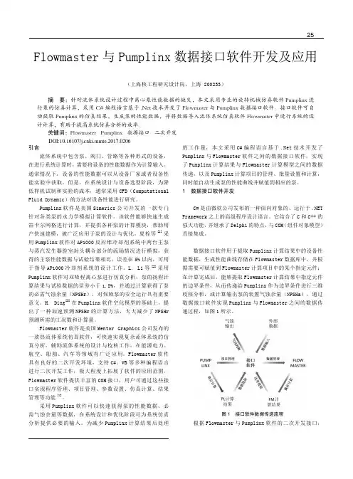
Flowmaster 软件是美国Mentor Graphics 公司发布的一款热流体系统仿真软件,可快速实现复杂流体系统的仿真分析,辅助流体系统的设计与校核工作,在能源电力、航空、船舶、汽车等领域有广泛应用。
Flowmaster 软件具有良好的二次开发环境,支持C#、VB 等多种编程语言进行二次开发工作,极大程度上拓展了软件的应用范围。
Flowmaster 软件提供丰富的COM 接口,用户可通过这些接口实现程序管理、项目管理、参数设置、仿真计算、结果管理等功能[4]。
采用Pumplinx 软件可以快速获得泵的性能数据、必需气蚀余量等数据,在系统设计和优化阶段可为系统仿真分析提供必要的输入。
PumpLinx常见问题FAQQ:PumpLinx软件的单位制是什么?为何在参数界⾯中看不到?从其它三维建模软件中导⼊的模型是否需要进⾏单位制的转换?A:PumpLinx采⽤的标准的国际SI单位制,各参数的单位均已集成到软件中,不过没有对⽤户可见,从外部导⼊模型时,⼀定要注意单位制的转换,⽆论模型所带的单位是什么,PumpLinx均按⽶制单位导⼊。
例如,有的客户在UG中以mm 为单位创建好了模型,导⼊到PumpLinx中进⾏计算时发现很难收敛,这就是由于未进⾏单位制的转换⽽造成的,100mm的尺度在导⼊PumpLinx时被放⼤到100m,可想⽽知,计算时⽆法正常进⾏的。
Q:PumpLinx对导⼊的⼏何模型⽂件格式有要求吗?⽤UG、CATIA、Pro-E这些建模软件创建的模型可以导⼊吗?A:有要求,PumpLinx要求导⼊的⼏何模型必须是STL格式的,通⽤的建模软件,包括UG、CATIA、Pro-E等均兼容这种格式。
Q:PumpLinx的计算域需要在模型导⼊之前就定义好吗?包括边界表⾯的划分、区域交界⾯的划分等等。
A:不需要,PumpLinx具有便捷实⽤的⼏何模型编辑功能,能⽅便快速地实现计算域的划分、边界表⾯的定义等功能。
不过需要注意的是,不同计算域之间的间隙必须⼤于交互⾯公差(⼀般情况下,间隙厚度0.1mm即可满⾜此条件)。
Q:PumpLinx⽹格⽣成⼯具⽣成的是什么样的⽹格?与其他的⽹格处理⼯具兼容吗?A:PumpLinx⽣成的是笛卡尔⽹格,⽬前,有PumpLinx⽣成的⽹格还⽆法在其他⽹格处理⼯具中兼容,不过PumpLinx可以兼容其他的⽹格形式,如,Nastran Grid,Gambit Neutral以及Ansys CDB等等。
Q:⽹格尺度是如何控制的?如何查看⽹格及节点的数量?A:PumpLinx⽹格尺度主要是通过“Maximum Cell Size”,“Minimum Cell Size”及“Cell Size on Surfaces”这三个参数来控制的,⼀般我们建议“Maximum Cell Size”与“Cell Size on Surfaces”的⽐值控制在2:1到4:1之间。
Q:PumpLinx软件的单位制是什么?为何在参数界面中看不到?从其它三维建模软件中导入的模型是否需要进行单位制的转换?A:PumpLinx采用的标准的国际SI单位制,各参数的单位均已集成到软件中,不过没有对用户可见,从外部导入模型时,一定要注意单位制的转换,无论模型所带的单位是什么,PumpLinx均按米制单位导入。
例如,有的客户在UG中以mm 为单位创建好了模型,导入到PumpLinx中进行计算时发现很难收敛,这就是由于未进行单位制的转换而造成的,100mm的尺度在导入PumpLinx时被放大到100m,可想而知,计算时无法正常进行的。
Q:PumpLinx对导入的几何模型文件格式有要求吗?用UG、CATIA、Pro-E这些建模软件创建的模型可以导入吗?A:有要求,PumpLinx要求导入的几何模型必须是STL格式的,通用的建模软件,包括UG、CATIA、Pro-E等均兼容这种格式。
Q:PumpLinx的计算域需要在模型导入之前就定义好吗?包括边界表面的划分、区域交界面的划分等等。
A:不需要,PumpLinx具有便捷实用的几何模型编辑功能,能方便快速地实现计算域的划分、边界表面的定义等功能。
不过需要注意的是,不同计算域之间的间隙必须大于交互面公差(一般情况下,间隙厚度0.1mm即可满足此条件)。
Q:PumpLinx网格生成工具生成的是什么样的网格?与其他的网格处理工具兼容吗?A:PumpLinx生成的是笛卡尔网格,目前,有PumpLinx生成的网格还无法在其他网格处理工具中兼容,不过PumpLinx可以兼容其他的网格形式,如,Nastran Grid,Gambit Neutral以及Ansys CDB等等。
Q:网格尺度是如何控制的?如何查看网格及节点的数量?A:PumpLinx网格尺度主要是通过“Maximum Cell Size”,“Minimum Cell Size”及“Cell Size on Surfaces”这三个参数来控制的,一般我们建议“Maximum Cell Size”与“Cell Size on Surfaces”的比值控制在2:1到4:1之间。
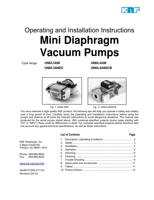
Operating and Installation InstructionsMini DiaphragmVacuum PumpsType range:UN84.3ANI UN84.4ANIUN84.3ANDC UN84.4ANDCBFig. 1: UN84.3ANI Fig.. 2: UN84.4ANDCBYou have selected a high-quality KNF product; the following tips will help you operate it safely and reliably over a long period of time. Carefully study the Operating and Installation Instructions before using the pumps and observe at all times the relevant instructions to avoid dangerous situations. The manual was produced for the serial pumps stated above. With customer-specified projects (pump types starting with “PU“ or “MPU“) there could be differences in detail. For customer-specified projects please therefore take into account any agreed technical specifications, as well as these instructions.List of Contents Page 1. Description, Operating Conditions ........................................... 2 2. Safety ...................................................................................... 3 3. Installation ............................................................................... 4 4. Operation ................................................................................ 5 5. Servicing ................................................................................. 6 6. Cleaning .................................................................................. 9 7. Trouble Shooting ..................................................................... 9 8. Spare parts and accessories ................................................. 11 9. Tables ................................................................................... 11 10. Product Return . (12)KNF Neuberger, Inc2 Black Forest RdTrenton, NJ 08691-1810Phone: 609-890-8600Fax: 609-890-8323/usa.htmIdent#121256-211123Revision (04/12)Diaphragm Vacuum Pumps UN84 Description, Operating Conditions1. Description, Operating ConditionsKNF pumps in the UN84 range transfer compress and evacuate100% oil-free. In operation they are gas-tight, and maintenance-free.1.1. Electrical EquipmentSee the motor-plate for full electrical data.Protection class of standard version is IP00.1.2. Operating ConditionsHandling air, gases, and vapours at temperatures between + 5 °C+ 40 °C.For maximum permissible operating pressure, ultimate vacuum,and flow capacity see section 9.The pumps must not be used in areas where there is a danger ofexplosion.Before pumping a medium, the compatibility of materials of pumphead, diaphragm and valves with the medium must be checked (forpump materials: see section 9).KNF pumps in the N 84 range must not be used for liquids. You willfind suitable liquid pumps in our Product Program.If your potential application lies outside the above limits discuss itwith our technical adviser (see last page for contact telephonenumber).1.3. Ambient ConditionsWhen the pump is operating the following ambient conditions mustbe maintained:Ambient temperature during operation: between + 5 °C+ 40 °C.The pumps must be protected from the effects of dust andwater.During operation an adequate supply of air for coolingmust be provided.The pumps must not be used in areas where there is adanger of explosion.1.4. Pump materialsSee section 9.2. SafetyThe pumps have Protection Class 00, and so offer noprotection against contact or foreign bodies. It is thereforeessential to provide protection for persons against contactwith live parts (e.g. electrical connections, motor windings),and moving parts (e.g. fan). Protection against the entry offoreign bodies must also be provided.The pump has no protection against water. In this case too, asfar as is relevant, measures to protect the pump must betaken before putting it into service.Note that the pumps may only be used for their intended purpose(see section 1).The pumps must not be used in areas where there is a danger ofexplosion.The pumps are not suitable for aggressive media.Components connected to the pump must be designed towithstand the pneumatic performance of the pump.Take care that safety regulations are observed when connectingthe pump to the electricity supply.For pumps with a thermal switch:When the operation of the pump is interrupted by the thermalswitch, the pump will re-start automatically after cooling down.Take all care necessary to prevent this leading to a dangeroussituation.Specific safety instructions for the media being handled must beobserved.Use only original KNF spare parts.For the purposes of the Machinery Directive 2006/42/EC, pumps EC Directives / Standardsare “partly completed machinery,” and are therefore to be regardedas not ready for use. Partly completed machinery may not becommissioned until such time as it has been determined that themachine in which the partly completed machinery is to beassembled is in conformity with the provisions of the MachineryDirective 2006/42/EC.The essential requirements of Annex I ofDirective 2006/42/EC (general principles) are applied andobserved.The pumps conform to the EC Directive 2004/108/EC concerningElectromagnetic Compatibility.The following harmonized standards have been used:UN84.4ANDCBUN84.3ANI UN84.3ANDCUN84.4ANDCDIN EN 55014-1/2 DIN EN 55014-1/2 DIN EN 55014-1DIN EN 61000-3-2/3DIN EN 60034-1 DIN EN 61000-6-2DIN EN 60335-1Tab. 1The pumps are OEM models intended for installation in equipment. When installing them make certain that accident prevention regulations, and safety instructions, including those for subsequent operation are observed. The safety instructions in section 2 must be observed. The dimensions of the mountings are given in Data Sheet. Install the pump so as to ensure adequate flow of air cooling. For pumps with fan: Install the pump so as accidental finger contact is with the fan is impossible. Fit the pump at the highest point in the system, so that condensate cannot collect in the head of the pump - that prolongs working life. For pump N84.3ANI: Rubber feet (accessories) may be used to reduce noise, and vibration. They are not suitable for mounting the pump on its side, or suspended. When making the electrical installation the safety regulations must be observed. In particular make sure that the electricity supply is isolated before trying to connect the pump. Compare the supply data with the data on the motor-plate. The voltage must not vary by more than +10% and -10% from that shown on the type-plate. The motor must be connected to earth (ground) wire (not neces-sary on dc motors up to 24 V). In the electrical installation, arrangements (complying with EN 60335-1) must be made for disconnecting the pump motor from the electrical supply. The pump must be installed so that contact with live parts (e.g. electrical connection) is impossible. For pumps with ac motor: We recommend that a fuse is installed in the supply circuit; the operating current is given in Data Sheet. Remove the protection plugs from the port threads.The accessories, silencer, and hose connectors (if available) arescrewed into the port threads.Connect the suction and pressure lines (thread size 1/8”NPT). Forflow direction, see the marking on the pump head or data sheet.Arrange the suction and pressure lines so that condensate cannotrun into the pump (sloping lines).MechanicalElectricalPneumaticSpecific safety instructions for the media being handled must be observed.Before pumping a medium, the compatibility of materials of pump head, diaphragm and valves with the medium must be checked (for pump materials: see section 9).If combustible media are used:Hazard of fires and explosions due to excessively high media temperature.Be aware that the pumps are not designed to be explosion-proof.Make sure the temperature of the medium is always sufficiently below the ignition temperature of the medium toavoid ignition or explosion. This also applies for unusualoperational situations.Note that the temperature of the medium increases when the pump compresses the medium.Hence, make sure the temperature of the medium is sufficiently below the ignition temperature of the medium,even when it is compressed to the maximum permissibleoperating pressure of the pump.The maximum permissible operating pressure of the pump is stated in the technical specifications (section 9).If necessary, consider any external sources of energy, such as radiation, that may add heat to the medium.In case of doubt, consult the KNF customer service.The pumps must not start against pressure or vacuum. When it is switched on the pressure in the suction and pressure lines must be atmospheric. This must be so even when the pump restarts after the power has been cut off for a short period.The maximum permissible operating pressure (see section 9) must not be exceeded.To prevent the maximum permissible operating pressure being exceeded, restriction or control of the air or gas flow should only be carried out in the suction line.If restriction or control of the air or gas flow is made on the pressure side, ensure that the maximum permissible operating pressure is not exceeded.When the pump is at a standstill the inlet and exhaust must be at normal atmospheric pressure.Diaphragm and valve plates are the only parts subject to wear. Wear is usually indicated by a drastic reduction in the pneumatic performance. When replacing parts proceed as described in section 5.Ambient conditions: see section 1.3.Before working on the pump, isolate the power supply securely, then check that the lines are not live. Diaphragm and valve plates are the only parts of the pump subject to wear. They are simple to change. Always change diaphragm, valve plates and sealing rings at the same time. Service all heads.Fig. 3 Sectional view (symbolic) Specification Pos. Description 01 Housing 02 Intermediate plate 03 Head plate 04 Screw 05 Connection 06 Cover 07 Valve plate 08 Sealing ring 09 Structured diaphragm 10 Diaphragm shim ring(s) 11 Diaphragm shim ring(s) 12 Eccentric 13 Connection rod 14 Counter Weight Spare part* Quantity Valve plates 2 (per pump head) Structured diaphragm1 (per pump head) Sealing rings2 (per pump head) Tab. 2 * According to Spare parts list, section 8 Tools/MaterialPhillips screwdriver No. 1Felt-tip penTab. 3Change the diaphragms, valve plates and sealing rings in thefollowing sequence:Fig. 4: (for the whole type range)Parts requiredTools requireda) Removing the pump headb) Changing structured diaphragmc) Changing valve plates and sealing ringsd) Refitting pump headWith the exception of removal and refitting of the cover plate (6) (twin headed pumps) or of two cover plates (four headed pumps) all operations are to be carried out separately for each head. This prevents the parts getting mixed up (the head plates are not identical).The position numbers in the following text refer to figs. 3 and 4. Proceed as follows:a) Removing the pump head1. Only for models with dc motors (no cooling fan): undo the 4screws securing the cover (6) to the pump housing (1), andremove the cover (6).On these models, which have no fan, where reference is made to turning or holding the cooling fan, the necessaryoperations must be carried out by turning or holding thecounterweight (14).2. For one head: Mark the position of the head plate (3),intermediate plate (2), and housing (1) relative to each other bya drawing line (M) with a felt-tip pen. This helps avoid incorrectassembly later.3. Undo the 4 screws (4) in the head plate and lift the head plate(3) with the intermediate plate (2) off the pump housing.b) Changing the structured diaphragm1. Turn the fan to bring the structured diaphragm (9) to top deadcentre.2. Lift the edge of the diaphragm, and gripping it on oppositesides, unscrew it by turning counter-clock-wise. Please takecare that the diaphragm shim ring(s) (10 & 11), on thethreaded portion of the diaphragm, do not fall into the housing.3. Take the diaphragm shim ring(s) (10 & 11) off the threadedportion of the diaphragm and retain them.4. Check that all parts are free from dirt and clean them ifnecessary (see section 6. Cleaning).5. Put the diaphragm shim ring(s) onto the thread of the newdiaphragm.Please note that the same diaphragm shim ring(s) must be used for new structured diaphragm.6. Turn the fan until the connecting rod (13) is at top dead centre.7. Screw the structured diaphragm, complete with the diaphragmshim ring(s), into the connecting rod (clockwise) and tighten it by hand.c) Changing the valve plates and sealing rings1. Separate the head plate (3) from intermediate plate (2).2. Remove the valve plates (7) and sealing rings (8) from theintermediate plate.3. Check that the valve seats in the head plate and intermediateplate are clean. If scratches, distortion, or corrosion are evident on these parts they should be replaced.4. Lay the new valve plates in the recesses in the intermediateplate. The valve plates for the suction and the pressure sides are identical, as are upper and lower sides of the plates.5. Check that the valve plates are not deformed by moving themgently sideways in their recesses.6. Lay the sealing rings on the intermediate plate.d) Refitting the pump head1. Turn the fan to bring the structured diaphragm (9) to top deadcentre.2. Place the intermediate plate (2) (with valve plates (7) andsealing rings (8)), and head plate (3) on the housing, in theposition indicated by the marking (M).3. Check that the head plate is centred by moving it gentlysideways.4. Gently tighten the screws (4), evenly and diagonally.5. Turn the fan to check that the pump rotates freely.6. Turn the fan again to bring the diaphragm to top dead centre.7. Now tighten screws (4) firmly.e) Second pump head1. Repeat operations a) (2.,3.) and b) to d) for the second pumphead.2. Reaffix the cover (6) to the housing (1).Only for type range UN84.4:Repeat operations a) to e) for the both remaining pump heads.If you have any questions about servicing call our technical adviser (see last page for contact telephone number).6. CleaningWhen changing valve plates and wave diaphragm, inspect all parts for dirt before assembling the pump head, and clean them if necessary.If a compressed air line is available, blow the parts out with it.7. Trouble ShootingBefore working on the pump, isolate the power supply securely and then check that the lines are not live.The following tips for fault-finding are best employed in the sequence shown.Pump produces no flowFor pumps with thermal switch:Thermal switch has opened due to over-heating.`Disconnect pump from mains and allow cooling.Trace cause of over-heating and eliminate it.Connections or lines are blockedAn external valve is closed, or a filter blocked.Liquid (condensate) has collected in the pump head.`Let the pump run for a few minutes pumping air (ifnecessary for safety reasons: pumping an inertgas.)`Install the pump at the highest point in the system.Diaphragms or valve plates are worn.` Section 5 Servicing.Flow, pressure, or vacuum too lowCompare the actual performance with the figures in section9 or the data sheet.There is pressure on the pressure side and at the same time vacuum or a pressure above atmospheric, on thesuction side.`The pump is not designed for this condition.The cross-section of pneumatic lines, or connected components is too small, or they are restricted.`To measure the performance, disconnect thepump from the system (small diameter tubing or avalve can significantly affect performance).There is a leak at a connector, in a line, or in the pump head.Diaphragm or valve plate are worn, or dirt is in the head: ` Section 5 Servicing.After changing the diaphragms or valve plates, a head has been reassembled in the wrong position.If the pump does not operate properly and you cannot find any of the above faults, send it to the KNF Service Department.In order for KNF to repair the pump, the customer must provide a statement on the media which were pumped and on pump cleaning. Please fill out the corresponding KNF form, and submit it together with the pump. A sample statement for copying can be found in section 10 of these operating instructions.Diaphragm Vacuum Pumps UN84 Spare parts and accessories8. Spare parts and accessoriesSpare partsPos. No* Spare part Order No.(2) Intermediateplate 055334(7) Valveplate 055353(8) Sealingring 055354(9) Structureddiaphragm 027578(10) Diaphragm shim ring (1.0mm) 027556(11) Diaphragm shim ring (0.1mm) 024986Tab. 4 *according Fig. 3 and 4AccessoriesDescription Order No.Silencer/Filter 072233Hose Connector 1/8 MPTM, ¼ HID 072235Rubber feet (for N 84.3 ANE)(2 pieces are necessary)024435Tab. 59. TablesPump type Max. permissi-ble operatingpressure (bar g) Ultimatevacuum(mbar abs.)Delivery rate*(l/min) at atm.pressureUN84.3ANI 0.3 7 4.2UN84.3ANDC 0.3 7 5UN84.4ANDC 0.3 2 4.8UN84.4ANDCB 0.3 2 4.8Tab. 6: Pneumatic Data *Litre at STP (1013 mbar);Pump type Material*Pump head StructureddiaphragmValveUN84.3ANI AluminiumalloyNeopren/PTFE EPDMUN84.3ANDC AluminiumalloyNeopren/PTFE EPDMUN84.4ANDC AluminiumalloyNeopren/PTFE EPDMUN84.4ANDCB AluminiumalloyNeopren/PTFE EPDM Tab. 7: Pump Materials *Material abbreviations according DIN ISO 1629Diaphragm Vacuum Pumps UN84 Product Return10. Product ReturnÎ KNF provides warranty and non-warranty repair services for allproducts. Î A Return Material Authorization (RMA) number is required forall product returns.• To receive an RMA number, submit a completed Decontamination Declaration form to *********** Î The Decontamination Declaration form can obtained from ourwebsite or by contacting KNF Technical Services.•/pdfs/decontamdec.doc• Phone: 609-890-8600Î Product return instructions will be provided when the RMA is issued.KNF Neuberger, Inc 2 Black Forest RdTrenton, NJ 08691-1810 Phone 609-890-8600 Fax 609-890-8323/usa.htm。
PetaLinux Tools User GuideInstallation Guide UG976(v2014.2)June3,2014Notice of DisclaimerThe information disclosed to you hereunder(the"Materials")is provided solely for the selection and use of Xilinx products.To the maximum extent permitted by applicable law:(1)Materials are made available"AS IS"and with all faults,Xilinx hereby DISCLAIMS ALL WARRANTIES AND CONDITIONS,EXPRESS,IMPLIED,OR ST ATUTORY,INCLUDING BUT NOT LIMITED TO ARRANTIES OF MERCHANT ABILITY,NON-INFRINGEMENT,OR FITNESS FOR ANY PARTICULAR PURPOSE;and(2)Xilinx shall not be liable(whether in contract or tort,including negligence,or under any other theory of liability)for any loss or damage of any kind or nature related to,arising under,or in connection with,the Materials(including your use of the Materials),including for any direct,indirect,special,incidental,or consequential loss or damage(including loss of data,profits,goodwill,or any type of loss or damage suffered as a result of any action brought by a third party)even if such damage or loss was reasonably foreseeable or Xilinx had been advised of the possibility of the same.Xilinx assumes no obligation to correct any errors contained in the Materials or to notify you of updates to the Materials or to product specifications.Y ou may not reproduce,modify,distribute,or publicly display the Materials without prior written consent.Certain products are subject to the terms and conditions of the Limited Warranties which can be viewed at /warranty.htm;IP cores may be subject to warranty and support terms contained in a license issued to you by Xilinx.Xilinx products are not designed or intended to be fail-safe or for use in any application requiring fail-safe performance;you assume sole risk and liability for use of Xilinx products in Critical Applications:/warranty.htm#critapps.©Copyright2014Xilinx,Inc.Xilinx,the Xilinx logo,Artix,ISE,Kintex,Spartan,Virtex,Vivado,Zynq,and other designated brands included herein are trademarks of Xilinx in the United States and other countries.All other trademarks are the property of their respective owners.Revision HistoryDate Version Notes2009-11-26 1.1Initial version for SDK1.1release2009-12-04 1.2Updated host package dependency list2010-12-02 1.3Updated supported OS list2011-04-04 2.1Updated for PetaLinux Tools2.1release-64-bit Ubuntu supported2012-08-03 3.1Updated for PetaLinux Tools3.1release2012-09-0312.9Updated for PetaLinux Tools12.9release2012-12-172012.12Updated for PetaLinux Tools2012.12release2013-04-292013.04Updated for PetaLinux Tools2013.04release2013-11-252013.10Updated for PetaLinux Tools2013.10release2014-06-032014.2Updated for PetaLinux Tools2014.2releaseOnline UpdatesPlease refer to the PetaLinux v2014.2Master Answer Record(Xilinx Answer Record#55776)for the latestupdates on PetaLinux Tools usage and documentation.Table of ContentsRevision History (1)Online Updates (2)Table of Contents (3)About this Guide (4)Prerequisites (4)PetaLinux Tools Installation (5)Run PetaLinux Tools Installer (5)Setup PetaLinux Tools Working Environment (5)PetaLinux Tools Licensing (6)Going Further (6)Troubleshooting (7)Required Tools and Libraries (10)Additional Resources (11)References (11)About this GuideThis document provides information on how to install the PetaLinux Tools.Please note:the reader of this document is assumed to have basic Linux knowledge such as how to run Linux commands.PrerequisitesThis getting started document assumes that the following prerequisites have been satisfied:•Minimum workstation requirements:◦2GB RAM(recommended minimum for Xilinx tools)◦Pentium42GHz CPU clock or equivalent◦5GB free HDD space◦Supported OS:RHEL5(32-bit or64-bit)RHEL6(32-bit or64-bit)SUSE Enterprise11(32-bit or64-bit)•Default shell"/bin/sh"is bash.•PetaLinux release package downloaded.Y ou can download PetaLinux from Xilinx Downloads.•Common system packages and libraries are installed on your workstation.The installation process will check for these.See the section Required T ools and Libraries for more details.IMPORTANT:If you are using a64-bit Linux host,you must install the appropiate32-bit compatablelibraries.Please refer to section Required Tools and Libraries.•Xilinx hardware tools(Vivado)and JTAG cable drivers are installed if you will be working with hardware projects and boards.PetaLinux v2014.2only works with Vivado2014.2.•Xilinx tool XSDK is installed if you will package bootfile for Zynq with PetaLinux.PetaLinux Tools InstallationRun PetaLinux Tools InstallerAssuming all the prerequisites described in the last subsection are satisfied,PetaLinux installation is very straight forward.PetaLinux tools does not require a license to install or run.Without any options,the installer will installl as a subdirectory of the current directory.Alternatively,an installation path may be specific.E.g.to install PetaLinux T ools under"/opt/pkg":$cd/opt/pkg$petalinux-v2014.2-final-installer.runor$petalinux-v2014.2-final-installer.run/opt/pkgBoth approaches will install the SDK into"/opt/pkg/petalinux-v2014.2-final"directory.Setup PetaLinux Tools Working EnvironmentAfter the installation,the remainder of the setup is completed automatically.1.Source the appropriate settings script:•For Bash:$source<path-to-installed-PetaLinux>/settings.sh•for C shell:$source<path-to-installed-PetaLinux>/settings.cshBelow is an example of the output from sourcing the setup script for thefirst time:$source/opt/petalinux-v2014.2-final/settings.shPetaLinux environment set to’/opt/petalinux-v2014.2-final’INFO:Finalising PetaLinux installationINFO:Checking free disk spaceINFO:Checking installed toolsINFO:Checking installed development librariesINFO:Checking network and other services2.Verify that the working environment has been set:$echo$PETALINUX/opt/petalinux-v2014.2-finalEnvironment variable"$PETALINUX"should point to the installed PetaLinux path.Y our output may be different from this example,depending upon where you installed PetaLinux.PetaLinux Tools LicensingPetaLinux tools do not require a license to install or run.By default,webtalk option is enabled to send tools usage statistics back to Xilinx.Y ou can turn off the webtalk feature by running the petalinux-util--webtalk command as follows:$petalinux-util--webtalk offGoing FurtherPetaLinux T ools installation is complete.Please refer to the PetaLinux T ools Getting Started Guide(UG977)document to build and boot yourfirst PetaLinux projects.TroubleshootingThis section describes some common issues you may experience when installing PetaLinux,and ways to solve them.If the PetaLinux installation fails,thefile"$PETALINUX/post-install.log"will be generated in your PetaLinux installation directory.Problem/Error Message Description and SolutionWARNING:Y ou have less than 1Gbyte free space on the installation drive Problem Description:This warning message tells that installation drive is almost full.Y ou may not have enough free space to develop your hardware project and/or software project after the installation.Solution:•Move the PetaLinux to another hard disk drive. Alternatively,•Cleanup the installation drive to clear some more free space.WARNING:No tftp server found Problem Description:This warning message tells that you don’t have a TFTP servicerunning on your workstation.Without TFTP service,you cannotdownload Linux system images to your MicroBlaze system usingu-boot’s network/TFTP capabilities.Solution:Enable the TFTP service on your workstation.If you are unsurehow to enable this service,please contact your systemadministrator.Problem/Error Message Description and SolutionERROR:GCC is not installed-unable to continue.Please install and retry Problem Description:This error message tells that you don’t have gcc installed on your workstation.Solution:Please install gcc using your Linux workstation’s package management system.If you are unsure how to do this,please contact your system administrator.ERROR:Y ou are missing the following system tools required by PetaLinux:missing-tools-list ORERROR:Y ou are missing these development libraries required by PetaLinux:missing-library-list Problem Description:This error message tells that you don’t have the required tools or libraries listed in the"missing-tools-list"or"missing-library-list". Solution:Please install the packages of the missing tools,Refer to section Required T ools and Libraries for details.Problem/Error Message Description and SolutionFailed to open PetaLinux lib.Problem Description:This error message indicates that a PetaLinux library failed to load.The cause of this issue is one of the following:•The PetaLinux"settings.sh"has not been loaded.•If the Linux Kernel you are running has SELinux configured.This can cause issues with regards to security context andloading libraries.Solution:1.Source the"settings.sh"script from the top-levelPetaLinux directory.2.If you have SELinux enabled,determine if SELinux is in’enforcing mode’.If SELinux is configured in’enforcing mode’eitherreconfigure SELinux to’permissive mode’(refer to SELinuxmanual),or change the security context of the libraries toallow access(see below for details).$cd$PETALINUX/tools/common/petalinux/lib$chcon-R-t textrel_shlib_t libRequired Tools and LibrariesPetaLinux requires a number of standard development tools and libraries to be installed on your Linux host workstation.The PetaLinux installation process checks for these packages,and reports an error if any are missing,however it does not attempt to install them -you must do this manually.This section describes the required packages,and how to install them on different Linux workstation environments.Tool/Library YUM/RPMPackage for RHEL/CentOS/Fedora APT Package for Debian/Ubuntu RPM Package for SuSE dos2unix dos2unix tofrodos dos2unix ip iproute iproute iproute2gawk gawk gawk gawk gcc gcc gcc gcc git gitgit-core git-core make gnutls-devel make make netstat net-tools net-tools net-tools ncurses ncurses-devel ncurses-dev ncurses-devel tftp server tftp-server tftpd tftp-server zlib zlib-devel zlib1g-dev zlib-devel flex flex flex flex bison bisonbisonbison 32bit libslibstdc++-4.4.6-4.el6.i686glibc.i686libgcc.i686libgomp.i386ia32-libslib32ncursesw5lib32gomp132-bit runtime environmentWARNING:Consult your system administrator if you are unsure about correct procedures for host system package management.Additional ResourcesReferences•PetaLinux Tools Application Development Guide(UG981)•PetaLinux Tools Board Bringup Guide(UG980)•PetaLinux Tools Firmware Upgrade Guide(UG983)•PetaLinux Tools Getting Started Guide(UG977)•PetaLinux Tools Installation Guide(UG976)•PetaLinux Tools QEMU System Emulation Guide(UG982)PetaLinux Tools Documentation is available at /petalinux.。
Q:Pumplinx计算时残差曲线收敛的标准是什么?有没有什么判定收敛的方法?纵坐标的数字代表的是10的数量级吗?A:收敛和其他CFD软件一样首先是按残差算。
除了残差,还要考虑整体守恒性(比如总质量流的守恒),以及所关心的物理量的变化情况(趋于稳定,或周期性等)。
残差的纵坐标是10的数量级。
Q:多级离心泵泵要关心级间的扬程,就是看每一级的扬程,那就是要得到第一级的出口跟第二级的进口交互面的压力,所以能不能对交互面的压力进行“plot”,就像是plot出口压力那样,而现在点击交互面plot后的列表里没有压力选项。
从结果文件integrals.txt里只有x,y,z轴上的压力(px_rotor_mgi_volute,pz_rotor_mgi_volute,py_rotor_mgi_volute),怎么得到这个面上的压力?A:Interface(交界面)可以输出总压。
需要按质量平均的总压用于每级间的扬程计算。
总压按内定是不输出的,所以你要手动加上。
先把模式改成”extended Mode“,然后选关心的界面,把”Output"改成“user select”,并加上“mass averaged total pressure”Q:现在加面的话只能是加垂直的面(x=2的面),能不能加斜的面?A:可以用斜面做切面。
选“Arbitrary Plane”就可以了Q:对容积泵来说稳定运行后泵有可能充不满油,这个能否模拟A:原则上可以,不过处理这样的问题目前的(空化)模型不是很理想,做的比较少Q:现在pumplinx做的都是稳定运行时的情况吧?能不能模拟泵启动的过程?就是油逐渐充满泵的过程,看一下什么时间充满什么程度,充满用多久…?A:可以,但没有太多验证算例Q:pumplinx生成文档-integrals.txt里,第一行标注(qa,qva,powa,q,qv,px,py,pz,tx,ty,tz,torq,pow,gas)的汉语意思?A:qa、qva和powa指的是平均质量流量、平均体积流量和平均功率;px、py、pz指的是压力;tx、ty、tz和torq指的是扭矩;gas指的气体体积质量分数。
Quick Installation GuideThis guide covers the installation and basic setup procedures for your AXIS 570/670 MIO. If you need more detailed instructions, please refer to the AXIS 570/670 MIO User’s Manual.Hardware InstallationEthernet 10baseT connectorEthernet 10base2 connectorNetwork IndicatorTest ButtonAXIS 570 MIORing Speed JumperNetwork IndicatorTest ButtonToken Ring STP ConnectorToken Ring UTP ConnectorAXIS 670 MIO1.Remove the cover plate over the MIO slot.2.Record the unit serial number. The serial number is the defaultEthernet or Node address which may found on the back of the AXIS 570/670 MIO circuit board. You will need this number during the network configuration.3.Switch off the printer.4.For AXIS 670 MIO only: Select the network Ring Speed using thejumper S4. With the jumper in place, the network speed is 16 Mbit/s. Remove the jumper to select 4 Mbit/s.5.Slide the AXIS 570/670 MIO board into place.6.Tighten the two screws securing the rear panel.7.Switch on the printer. The hardware installation is now complete.Installing the AXIS 570/670 MIONetwork setup is most easily done using the AXIS NetPilot™. However, if you do not have any computers running Windows, NetWare or NetBIOS/NetBEUI you may also use the printer’s front panel for basic configuration. Both methods are fully described in the User’s Manual.Proceed with the following instructions, as appropriate for your type of network. Refer to all relevant sections if you intend to use the AXIS 570/670 MIO in a multiprotocol environment. NetwareBy following the instructions detailed below, install your AXIS 570/670 MIO with the AXIS NetPilot™ installation Wizard, supplied on the AXIS Utilities disk. Please note that the AXIS NetPilot™ software will require a Windows platform that uses either NetWare or NetBIOS/NetBEUI.1.Load the AXIS NetPilot™ software by following the instructionson the label of the AXIS Utilities disk. After loading the software, double click on the NetPilot™ icon.2.The AXIS NetPilot™ will scan the network for Axis NetworkPrint Servers that have not been installed and your AXIS570/670 MIO will subsequently feature as a New Axis Unit.Select your AXIS 570/670 MIO from the Contents of ‘New Axis Units’ and then click the Install icon. The Installation Wizard will then guide you through the basic installation.Should you require assistance with any of the operations click the Help icon and follow the instructions provided in the Help window. To set up print queues:1.Select the Network Print Server to be set up by clicking its icon.2.Choose Network from the Setup menu.3. A new window will open that allows you to create print queues,connect the AXIS 570/670 MIO to print queues, and selecteither Print Server mode or Remote Printer mode for eachprinter.To set up the advanced operating parameters:1.Select the Network Print Server to be set up by clicking its icon.2.Choose Properties from the Setup menu.3. A set of Property Pages are opened which allow you to set up theway in which Print Server mode and Remote Printer modeoperate. You can also enable the frame types to be used.The setup is now completed and you can close the AXIS NetPilot™. Open a Windows application, e.g. Microsoft Word and then select Print... to ensure that your printer appears as the default printer. Make a test printout to verify that the AXIS 570/670 MIO is functioning correctly.UNIXUNIX Please note that you need UNIX root privileges, or administrator privileges on a Windows NT server for this configuration procedure.1.Acquire an unused Internet Address from your NetworkAdministrator and choose a unique name for your AXIS 570/670 MIO.2.Add your AXIS 570/670 MIO IP address and host name to yoursystem host table by appending the following line to the/etc/hosts file: <internet address><host name>Example:192.36.253.96salesdept3.Update your alias name databases (YP/NIS).4.Perform the following commands to download the InternetAddress and verify correct Internet communication:AXIS 570 MIO Ethernet Print Server:arp -s <host name> <node address> tempping <host name>Example for Ethernet:arp -s salesdept 00:40:8c:10:00:86 tempping salesdeptAXIS 670 MIO Token Ring Print Server:arp -s 802.5 <host name> <node address> tempping <host name>Example for Token Ring:arp -s 802.5 salesdept 00:02:31:48:00:61 temp ping salesdept5.Log in to the AXIS 570/670 MIO and up-load the axinstallscript:Example: (user entries appear in bold)> ftp salesdeptName (salesdept:thomas): rootPassword: pass(not visible)ftp> get axinstallftp> bye6.Execute the script:sh axinstall↵The directions displayed on the screen will then guide youthrough the installation of LPD, FTP or PROS on your UNIX system.The UNIX Configuration is now completed.Notes:t The Node Address is based upon the serial number of the AXIS 570/670 MIO but may optionally be a Locally Administrated Address.t You may alternatively use the RARP, BOOT or DHCP command to set the Internet Address; refer to the User’s Manual Section 7.Macintosh There is no support for Apple TokenTalk in the AXIS 670 MIO.Open the Chooser window by selecting Chooser in the Apple menu. Follow these steps to choose a printer:1.Click on the LaserWriter (or LaserWriter 8.0) Icon.2.If your network has more than one zone, click the name of the default zone.3.Click the name of the printer you want. The default printer name is shown as: AXIS<nnnnnn>_<port>, where <nnnnnn> is the last six digits of the serial number, and <port> is MIO.4.For LaserWriter 8.0 printer driver only:Click Setup..., and then Select Auto Setup. If the printer, just as the print server, supports bi-directional printing the installation will then be automatically performed. If not, you will be prompted to select a PPD file matching your printer, then click OK.5.Click the close box. This completes the configuration.Repeat this procedure for each Macintosh using the AXIS 570 MIO. Windows Unless you wish to change the default name of your AXIS 570/670 MIO, the setup operation within a Windows environment may be performed solely with the AXIS Print Utility for Windows, supplied on the AXIS Utilities disk. Perform the installation using the AXIS NetPilot™ should you wish to change the default name.Follow the instructions on the AXIS Utilities disk label to install the AXIS Print Utility for Windows on all workstations using peer-to-peer printing.The AXIS 570/670 MIO setup for Windows comprises installing the AXIS 570/670 MIO printer ports as Windows printer ports, and connecting the ports to a Windows printer driver.Peer-to-peer vs. Client-Server printing All users requiring access to a network printer in peer-to-peer mode will need to install the AXIS Print Utility for Windows software onto their workstation. Client-server mode requires only one user to install the AXIS Print Utility for Windows software onto their workstation.Client-server printing is suitable for larger networks and applications requiring central monitoring and priority management. The setup procedure for this print method is described below:1.Install AXIS Print Utility for Windows onto the file server.2.Set up your AXIS 570/670 MIO from the file server as described in the following sections, but check the Share box for your printer.Apple EtherTalk WindowsYour shared printers can now be used by all the Windows clients and you do not need to install the AXIS Print Utility on the clients.Note:t the server setup should only be made on a Windows forWorkgroups workstation.The procedures in the following sections describe how to setup the AXIS 570/670 MIO for peer-to-peer printing. This print method does not require a file server and is recommended for smaller networks.Windows 3.1Windows 3.1 requires that network support such as LAN Server or LAN Manager Workstation software is installed in order to redirect a local printer port to a network device. If this is the case, proceed as described under Windows for Workgroups below.Windows for Workgroups Follow these steps to install your AXIS 570/670 MIO forpeer-to-peer printing at a Windows for Workgroups workstation:1.Double-click the AXIS Print Utility icon.2.In the Port menu, click Add.3.In the NPS Port list, select the AXIS 570/670 MIO port to be installed. The ports appear as <name>.MIO, where <name> is AX followed by last six digits of the AXIS 570/670 MIO serial number. For example: AX570B35.MIO. Note that thisalphanumeric name will be superseded by any new name given to your AXIS 570/670 MIO when using the AXIS NetPilot™.4.Accept or change the suggested Windows port name, and type any comments in the Description field. Make a note of the Windows port name as you will need this later. Click OK to install the Windows port.5.In the Port menu, click Connect to bring up the Windows Printers dialog.6.Select a printer driver from the list of Installed Printers, or click Add>> to install a new driver. Click Connect...7.Select the Windows port name defined in step 4 above that should now feature at the bottom of the Ports list.8.Click OK to close the Connect dialog, and Close to close Printers.The setup is completed and you can now print through your AXIS 570/670 MIO.Important note:t AXIS Print Utility for Windows must be running when youprint through your AXIS 570/670 MIO. We stronglyrecommend that you copy the AXIS Print Utility icon into your StartUp file.Windows WindowsWindows 95Follow these steps to install your AXIS 570/670 MIO for peer-to-peer printing at a Windows 95 workstation:1.Double-click the AXIS Print Utility icon.2.In the Port menu, click Add.3.In the NPS Port list, select the AXIS 570/670 port to be installed.The ports appear as <name>.MIO, where <name> is AX followed by last six digits of your print server number. For example: AX570B35.MIO. Note that this alphanumeric name will be superseded by any new name given to your AXIS 570/670 MIO when using AXIS NetPilot™.4.Accept or change the suggested Windows port name, and type any comments in the Description field. Make a note of the Windows port name as you will need this later. Click OK to install the Windows port.5.In the Port menu, click Connect to bring up the Printers folder.6.Double-click the Add Printer icon. The Add Printer Wizard will then guide you through the installation. Click Next to proceed.7.Choose Local Printer, then click Next.8.Choose the appropriate Manufacturer and Printer model, and then click Next.9.Select the Windows port name from step 4, then click Next.10.Accept or change the suggested Printer Name, then click Next.11.Click Finish to complete the installation.The setup is completed and you can now print through your AXIS 570/670 MIO.Important note:t AXIS Print Utility for Windows must be running when you print through your AXIS 570/670 MIO. We stronglyrecommend that you establish a shortcut to the AXIS Print Utility in your StartUp file.Windows NTFollow these steps to install your AXIS 570/670 MIO for peer-to-peer printing at a Windows NT workstation:1.Double-click the AXIS Print Utility icon.2.In the Port menu, click Add.3.In the NPS Port list, select the AXIS 570/670 MIO port to be installed. The ports appear as <name>.MIO, where <name> is AX followed by last six digits of the AXIS 570/670 MIO serial number. For example: AX570B35.MIO. Note that thisalphanumeric name will be superseded by any new name given to your AXIS 570/670 MIO when using AXIS NetPilot™.WindowsWindows4.Accept or change the suggested Windows Port name, and type any comments in the Description field. Make a note of the Windows Port name as you will need it later, then click OK to install the Windows Port.5.In the Port menu, click Connect to bring up Print Manager.6.In the Printer menu, click Create Printer.7.Type a name in the Printer Name field, select a suitable printer driver from the Driver list, and select Other... in the Print to list.8.In the Print Destinations dialog, select Local Port, then click OK.9.In the Port Name field, type: C:\~\<port>where C:\~ is your spool directory, and <port> is the Windows Port name from step 4. Click OK.10.Close the Print Manager. The setup is complete.Important note:t AXIS Print Utility for Windows must be running when youprint through your AXIS 570/670 MIO. We stronglyrecommend that you copy the AXIS Print Utility icon into your StartUp file.OS/2Firstly, ensure that the NetBEUI protocol is active. If necessary, use MPTS/LAPS (LAN Server) or SETUP (LAN Manager) to activate it.Load the AXIS Print Utility for OS/2 and install the unit, as follows:1.Insert the Print Utilities for OS/2 disk into your disk drive, and open an OS/2 window. Execute the install.exe program .2.With the AXIS Print Utility running, install your AXIS 570/670 MIO by clicking Install . The ports appear as <name>.MIO, where <name> is AX followed by last six digits of the AXIS 570/670 MIO serial number. For example: AX570B35.MIO. Note that this alphanumeric name will be superseded by any new name given to your AXIS 570/670 MIO when using AXIS NetPilot™.3.Select the ports you want to install, then click Install .Repeat this procedure for each server using the AXIS 570/670 MIO.Create a Print Queue (OS/2 version 1.x):1.Double-click the Print Manager icon, click Setup then Printers...2.Click Add to make a new printer definition, then type a name of your choice in the Name field.3.Select \PIPE\<name>.MIO from the Device list, then select a printer driver suitable for your printer.4.Click Add, then click OK to confirm the printer definition.5.Click Setup, then select Queues...6.Click Add to create a print queue. Type a name in the Name field.7.Click Add, then click OK to confirm the queue definition.UNIX OS/2Create a Print Queue (OS/2 version 2.x and above):1.Double-click the Templates folder, then drag the Printer icon out to the Workplace Shell (or into a folder) while holding the right mouse button down.2.Type a name of your choice in the Name field.3.Select \PIPE\<name>.MIO from the Port list, and select a printer driver suitable for your printer from the Standard Printer list.4.Click OK to confirm the printer definition.Print queue sharing:Open an OS/2 window and issue the following command:NET SHARE queue_name /PRINT, where queue_name is the name of the queue to be created.Important note:t AXIS Print Utility for OS/2 must be running when you printthrough your AXIS 570/670 MIO. We strongly recommend that you copy the AXIS Print Utility icon into your StartUp file.SNA The AXIS NetPilot™ can be used to setup SNA and IBMemulation parameters in the AXIS 570/670 MIO. To configure your IBM host please refer to Section 3 of the AXIS 570/670 MIO User’s Manual.Web Management After setting the Internet Address and Host Name in the AXIS 570/670 MIO, as described in the UNIX section of this document, you are then able to access your AXIS 570/670 MIO from anystandard Web browser. To do this simply enter the Internet Address of the AXIS 570/670 MIO as a URL in your browser, as follows:http://192.36.253.96, orhttp://salesdeptThe Home Page of the AXIS 570/670 MIO will now be displayed in your browser, where links to the AXIS 570/670 MIO Configuration, Management, Status, Account, and Help services are readily available.UNIX SNA UNIX InternetAXIS 570/670 MIO Quick Installation GuidePart No: 15194Revision: 2.1, Date: March 1997Copyright © Axis Communications AB, 1997SwedenAxis Communications ABPhone: +46 46 270 18 00, Fax: +46 46 13 61 30Email:*************,URL:USAAxis Communications Inc.Phone: 1-800-444-AXIS, (617) 938-1188, Fax: (617) 938-6161 Email:****************,URL:/FranceAxis Communications SAPhone: +33 1 49 69 15 50, Fax: +33 1 49 69 15 59JapanAxis Communications K.K.Phone: +81 3 3663 8801, Fax: +81 3 3663 8802Email:***************.jpSingaporeAxis Communications Pte Ltd.Phone: +65 250 8077, Fax: +65 352 1655Email:*************.sgHong KongAxis Communications Ltd.Phone: +852 2836 0813, Fax: +852 2573 5935Email:*************.hkChina (Beijing Office)Axis Communications Ltd. Beijing OfficePhone: +86 - 10 6856 1350, Fax: +86 - 10 6856 1359China (Shanghai Office)Axis Communications Ltd. Shanghai Office Phone: +86 - 21 6280 8527, Fax: +86 - 21 6280 6892。
Q:PumpLinx安装过程大概需要多久?需要安装其他组件吗?
A:PumpLinx安装相对比较容易,“一键式”的安装能够确保软件安装过程不会出错,对于一般配置的电脑,也只需要几分钟便可完成安装。
对于服务器端,还需要安装License服务器,而对于客户端,只安装软件即可。
Q:PumpLinx对电脑操作系统有何要求?是否兼容64位机?
A:PumpLinx对操作系统的兼容性较好,Windows 2000/XP/Vista/Win 7均可安装,Linux操作系统也可以安装。
另外,PumpLinx可以在64位机上安装使用,安装时注意选择64位专用的安装程序即可。
Q:如何获取软件使用许可?
A:软件安装好之后,在获取有效的License之前是无法正常使用的,用户需要将打开软件时弹出的错误信息提示框中的“Local Hardware ID”号提供给海基,并由海基向Simerics公司提供申请,一般情况下,只需1-3个工作日,便可将有效的License提供给用户。
Q:申请到的License如何设置?
A:License分为固定式和浮动式两种,对于浮动式License,首先需要在服务器端安装“License Server Installation”,安装完成之后,该程序将在“开始-所有程序-Simerics”中产生四个选项,将申请到的floating license拷贝到license server安装目录下,如C:\Program files\Simerics,并将license文本第一行中的localhost 替换为服务器的计算机名,然后在“开始-所有程序-Simerics”中运行Start License Server。
服务器启动后,在客户端机器上的Simerics安装路径下新建license.txt 文件,并将floating license中的第一行语句拷贝至该文件中,并将localhost替换为服务器计算机名,保存后即可启动软件。
对于固定式License,只需将申请到的License拷贝至软件安装目录下即可。
Q:为何License配置好之后,软件还是无法正常启动?
A:请依次尝试以下解决办法:
✓请核对错误提示框中的Hardware ID号是否与初始申请时一直,因为网络设置的改变也会引起Hardware ID的改变,如网络连接的添加\删除或者
启用\禁用等。
✓请检查客户端是否有权限访问服务器,网络服务是否正常。
✓可将客户端机器License中的机器名称替换为服务器的IP地址。
✓检查防火墙设置,是否屏蔽了PumpLinx软件端口。
✓检查服务器的License Server是否已启动,如未启动,点击“开始-所有程序-Start License Server”。
Q:PumpLinx有汉化版吗?
A:有,请联系海基销售人员,申请软件汉化包,即名为PumpLinx_Chinese.slang 的文件,将该文件拷贝到PumpLinx安装目录下,如C:\Program Files\Simerics,打开PumpLinx软件View-Language,进行选择。