三星贴片机SM421程序的编写
- 格式:pdf
- 大小:2.46 MB
- 文档页数:53

三星贴片机操作范文一、三星贴片机的基本操作流程1.初始化将电路板放置在贴片机上,并使用夹具将其固定。
然后按下贴片机面板上的初始化按钮,系统会进行自检并回到初始状态。
2.设定引导标点贴片机需要知道电路板的准确位置和尺寸。
通过设定引导标点来实现,即从电路板的四个角落选择四个指定的标点。
在贴片机面板上选择“标点设定”选项,按照指引依次设定四个引导标点。
3.加载元件将需要贴装的元件放置在三星贴片机的自动供料仓中。
按照元件的大小和类别进行分类,避免元件之间的混淆。
4.设定元件数据在贴片机面板上选择“元件数据设定”选项。
根据电路图和元器件清单,输入元件的相关参数,包括型号、尺寸、定位、元件描述等信息。
5.创建贴装程序6.开始贴装在贴片机面板上选择“开始贴装”选项,系统会自动进行元件贴装。
贴片机会根据设定的贴装程序,自动识别元件并进行精确定位和贴装。
7.检查贴装结果贴装完成后,需要进行质量检查。
可以使用目视检查或专业检测设备来检查每个元件的位置、焊接质量和贴装准确度等。
二、三星贴片机的注意事项1.元件供料要确保元件供料仓中的元件充足并正确放置。
定期检查元件供料仓的状态,及时补充或更换元件。
2.元件数据的准确性在设定元件数据时,需要确保输入的元件参数准确无误。
错误的元件参数会导致贴装错误或质量问题。
3.引导标点的准确定位引导标点的正确设定是保证贴装准确度的重要步骤。
需要仔细选择引导标点,并准确设定其位置。
4.贴装程序的创建在创建贴装程序时,要根据电路板设计和元件数据准确地设定贴装顺序和参数。
不同尺寸和类型的元件应设定相应的贴装速度和高度等。
5.贴装速度的控制贴片机的贴装速度会影响贴装效果和质量。
速度过快可能引起元件错位或其他不良贴装现象,速度过慢则会影响生产效率。
根据具体情况选择合适的贴装速度。
6.检查贴装结果贴装完成后,一定要进行贴装结果的检查。
使用目视检查或专业检测设备,确保每个元件的位置和焊接质量符合要求。

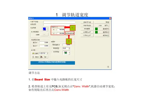
1 调节轨道宽度12调节方法1. 在Board Size 中输入电路板的长宽尺寸2 PCB 原点设置---步骤1设置方法:1. 按动AXIS 键,使X Y 轴灯亮2. 按动MODE 键,使JOG 或BANG 灯亮3. 选择一个焊盘的直角位置,按下方向键使显示屏的十字架的交点指示在该直角的位置,(如下图的R127右下角)R127方向键xy 轴灯45 61.设置拼板排列x y3拼板设置---步骤34. 按动AXIS 键,使X Y 灯亮5. 按动MODE 键,使JOG 或BANG 灯亮6. 按下方向键使显示屏的十字架的交点指示在第二块PCB 的R127的位置,如下图 R127方向键xy 轴灯第二块PCB 工作模式7810129拾取坐标的方法127 69一一对应基准点的中心颜色在此选择调节相机亮度White :中心比周围白Black :中心比周围黑131617绿色状态时点OK235469 78光标在此元件参数编辑按钮点此选择吸头号准备手动吸取108913二元图象12设置照明环境实际图像显示二元图像显示16选择元器件的包装形式1513 2Feeder Base 1:前面2:后面站号4567点击 后出现4814.当前有效位置16.元件检测角度13.选择相机类型15选择元件规格X 方向的格子数量Y 方向的格子数量1233rd-13rd-22nd-22nd-17911 8123选择相机号光标在此直接输入贴装角度89101112356784移动按钮需要用到的吸嘴型号1112 1314。

名称三星SM421贴片机设备维护保养操作指引生效日期2012-8-1三星(SM421)贴片机操作与维护保养指引一、目的对本公司贴片机进行维护保养,确保贴片机正常使用。
二、适应范围适应于本公司贴片机设备的维护保养和管理。
三、职责操作员:负责设备的护盖清扫等日常检验。
技术员:机器的调试,周、月保养以及异常处理。
工作负责人:负责设备的质量验证,对本项目的安全质量负责。
四、操作步骤进行维修作业时必须遵守如下过程:1、确认装备的所有作业是否结束。
2、维修作业开始前,必须关闭电源,并关闭装备主电源。
3、测定及维修作业必须由具有充分资格的职员来进行。
4、注意避免系统重新开启,若不遵守此项,触摸通电流零件时会造成死亡或重伤的事故。
维修作业结束后,为了正确运行装备要遵守如下过程:1、确定进行维修作业的地方有无障碍物,若有的话去除。
2、确认所有零件是否正确组装。
3、打开装备主电源。
4、按照电源检查方法打开设备电源。
5、确认装备的运行是否正常。
五、作业内容□用语说明◆吸嘴内径◆NOzzle Holder是指拧紧在Spindle的终端,连接吸嘴的器具。
◆Spindle 是指旋转的小轴,属于装备的HEAD组件,在终端有Holder,通过非常精密驱动的同步名称三星SM421贴片机设备维护保养操作指引生效日期2012-8-1皮带AC伺服电机进行取料、置件的Z轴动作,并用Micro步进电机进行修改零件位置的轴动作。
◆ Head组合件它由支持Head组合件的器具、空压设备的Head、Body、轴、驱动马达、负责影响识别的飞行影像组合件和示教摄像机组件等组成。
◆摄像系统(Vision System)『基准摄像机』Fiducial Camera示教摄像机组合是基准摄像机和基准摄像照明的统称,主要用于示教时的位置确认和基准标志的识别。
『飞行影像』Flying Vision主要用于小零件的识别。
名称三星SM421贴片机设备维护保养操作指引生效日期2012-8-1□日常检查◆吸嘴检查1、吸嘴的终端有无因受冲击而发生的变形或偏磨损,并确认吸嘴的内部有无异物堵塞。
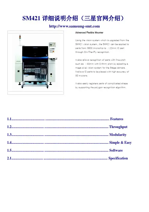
SM421详细说明介绍(三星官网介绍)Advanced Flexible MounterUsing the vision system which is upgraded from theSM421 vision system, the SM421 can be applied toparts from 0603 microchip to ∴22mm IC partthrough On-The-Fly recognition.It also allows recognition of parts with fine pitchsuch as ∴55mm with 0.4mm pitch by adopting amega pixel vision system for the Stage camera.It allows IC parts to be placed with high accuracy of30 microns.It also easily registers parts of complicated shapeby supporting the polygon recognition algorithm.1.1............................................................................................................... Features1.2..............................................................................................................Throughput 1.3.............................................................................................................. Modularity 1.4.............................................................................................................. Simple & Easy1.5.............................................................................................................. Software2.1............................................................................................................. Specification➢Features➢ThroughputThe unique On-The-Fly image recognition technology of Samsung Techwinown that allows part recognition without stopping after part pickup, minimizingthe time of movement between pickup position and placement position andmaximizing the placement speed by zeroing the recognition time.• Placement Speed:42,000 CPH (IPC9850),51,000 CPH (Optimal Condition)By adopting a dual work conveyor and shuttle inlet conveyor of first-in-firstout type, the PCB feeding type wasminimized and gantry efficiency is maximized due to elimination of a common work area, thus maximizing theactual productivity. Each gantry can work at full speed independently without risk of interrupting the opposinggantry. In addition, it supports various placement modes according to production characteristics and board size.The twin servo system applied to each axis of the gantry structure allows high speed placement bystrong accelerating force.• Equipped with self motion controller• Reinforced rigidity of driving system• Implementation of high acceleration and low vibration• Reduced setting time• Reinforced absolute accuracy and repetition accuracyChip ±50㎛(Cpk≥1.0),IC±30㎛(Cpk≥1.0)The newly upgraded placement accuracy calibration system automatically checks and calibrates the pickup point offset, head offset, C/V offset, etc. to allow reliable part placement.•Absolute Accuracy : ±50㎛(Cpk≥1)➢ModularityIt has an enhanced part registration library to allow quick part registration as well as stable part recognition and placement, and supports the polygon recognition related to unregistered part to allow the parts of complicated shape to be registered easily.The mega pixel camera allows the placement of parts from 0603(01005) micro chips. The SM400 series machine also allows recognition of larger parts with fine pitch or balls using 45mm camera such as □42mm with 0.4mm pitch by adopting a me ga pixel vision system for the Stage camera.The SM Series dual-lane conveyor system accommodates PCBs up to 250mm, increasing the overall placement speed. The system can also accommodate PCBs up to 460mm on a single-lane conveyor.The highest productivity compared to the area of machine : 11,700 CPH/m2➢Simple & EasyThe height of the machine was lowered through ergonomic redesign and the operation panel and keyboard position were optimized for convenient operationTwo operating consoles allow access to system controls from both the front and rear sides of themachine.All utility connections are installed inside the machine to provide aclean and safe environment.For the grease injection that is periodically performed during maintenance, the position of the nipple was considered for convenient grease injection.Samsung’s optional IT Feeder System assures correct feeder positioning because it checks the replaced feeder locations every time a component is loaded. The machine does not enter production mode when feeders are loaded incorrectly. It alerts the operator and provides easyto- follow instructions for corrective action.IT Feeder FeaturesBuilt-in CPU Board / Use of Device Net / Maintenance Record / Storage of Component No., Component Inventory, etc. / Component Shortage Warning LED / Feeder Recognition / ConfirmationFeeder Placement VerificationPerforms a changeover setup verification each time a feeder is reinserted. This feature saves valuable time and avoids costly rework due to incorrect feeder positioning.Remaining Component Quantity AlarmHelps to ensure continuous system operations. This basic function of the IT Feeder System alerts the operator that a component supply needs to be replenished, based on the remaining quantity.Production Information Tracking / Recording FunctionAutomatically tracks and generates a record of production information, such as operation hours, program developer, operated equipment, worked on components, etc.A machine checking software that automatically warns the time required for maintenance of the machine.Creates automatic placement routines on any number of machines in a production line, to configure the most productiveline balance for any environment or series of products.The SM Series features built-in optimizer software to ensure exceptionally efficient machine operation. Itautomatically configures the optimum feeder set-up and most efficient program sequence according touser-defined priority conditions. This function minimizes changeover while maximizing machine runtime.Top-quality accessories, such as non-stop tape feeders and non-stop tray feeders, increase overall system reliability and help significantly reduce amount of machine downtime.Non-Stop Tape FeederThe new SM tape feeder employs an endless-discharge method of nonstop operation in delivering reliable,repeatable, and efficient component pickups. Components supplied on tape can be reloaded easily while themachine is running, ensuring smooth continuous system operation(SM Tape Feeder).Non-Stop Tray FeederJEDEC tray cassettes are separated into upper and lower portions and can operate independently. Traycomponents also can be reloaded while the machine is running, enabling consistent non-stop operation.Side Tray FeederEntire JEDEC trays can be presented to the machine without any impact on PCB process width or availablefeeder slot locations, allowing for direct pick-up from tray and maximum efficiency of feeder space.Non-Stop Tape SplicingProvide a continuous, steady supply of available components quickly and easily using a component tape connecting splicer.Automatic Pickup Position AdjustmentSM Series systems perform real-time recognition of a component as it is picked up from the component feeder.This feature provides the ability to automatically adjust the pickup position, ensuring that components are pickedup consistently at the center, regardless of tape variations.Improved Accuracy• High feeder base stability• New mounting mechanism• Two position-control pins at the front side• Newly designed sprocketStable Indexing• Built-in cylinder• Optimized pressure control within the cylinder• Increased pick-up speeds with the index sensor• Tape guide automatically compensates for changes in tape thickness• Variable tape support (for feeders accommodating tape widths of 12mm and higher) Easy to Use• Swing-type reel hanger (splicing/verification)• Easy feeder identification by applying a different color for eachclamp (01005, 0201, 2p, 4p, 4E, general feeder)• Ergonomic handle design• Manual index switch (IT option)• Power supply indication lamp illuminates when fixed by the clamp• Tape guide lift prevention through the use of the control pinSamsung’s Docking Feeder Cart System is the key to rapid changeo ver. A Docking Feeder Cart can be loaded offline, and then quickly rolled up to the machine where it is pneumatically clamped to the feeder base. Both the front and rear sides of the SM Series machines are designed to accommodate the Docking Feeder Cart System.• Significantly reduce changeover time• Replace carts without halting production• Accommodates up to 56 8mm feeders per cart• Automatically connects to feeder power and air supply• Easily set the cart height using adjustable feetRegister up to 120 8mm feeders on one machine simultaneously. Concurrent optimizer support for 1 to 5programs allows for multiple models to be arranged at the same time. The sliding-type feeder systempermits the user to remove and replace feeders during operation without interrupting the overall system.The SM series can automatically generate a Job Change Order Sheet (feeder changeover report) while running productionin order to minimize setup time. This report identifies only the feeders that need to be changed, eliminating the need tocompletely reload the machine.The board transport system automatically adjusts to the precise board width in order to furtherfacilitate quick changeover.SM Series systems use nozzles that are common to other Samsung SMT assembly systems, allowing for interchangeability and optimal line balancing. With the increase in popularity of more delicate micro components, SM series systems have incorporated features to handle the demands of such products, specifically using nozzles with compliant mechanisms in order to prevent component damage.• Ceramic Nozzle • Bare Component Soft PAD Nozzle (Optional)Feeder Types/Sizes Feeder Pitch(mm)8mm (1005/0603) 8mm12mm16mm24mm32mm44mm56mm72mm88mm 244, 8, 124, 8, 128, 12, 16, 208, 12, 16, 20, 24, 32 8, 12, 16, 20, 24, 32, 40 8, 12, 16, 20, 24, 32, 40 8, 12, 16, 20, 24, 32, 40 8, 12, 16, 20, 24, 32, 40• Adjustable frequency control• 24 VDC, 0.8A 0.8• Maximum of four lanes• Applicable components - SOP, SOJ, QFP, PLCC, connector, etc.• Dual level magazine racks allow the component trays to be loaded while the machine is runni ng • Large capacity tray feeder for various odd-shaped components• 20 Tray (1 Tray / 1 Pallet)• 40 Tray (2 Tray / 1 Pallet)•One-touch mounting allows the tray to be easily inserted and removed from feeder base.• Flat tray installation surface enables high speed pickup.• M ultiple orientations, based on tray dimensions• Applicable Trays : 2", 4", 136 x 316mm, 200 x 316mm, 272 x 316mm• Type : Single-layer tray feeders (136 x 316mm) with 2 traysSingle-layer tray feeders (136 x 316mm) with 4 traysSignificantly reduce changeover time using the SM Series Docking Feeder Cart System. The system allows for replacing a complete feeder configuration in just minutes.Basic Set Configuration• Docking Feeder Base• Docking Cart• Minimize the space required to store unused or staged SMfeeders• SM feeder storage rack with 100 slots provides storage capacity for up to 100 SMfeeders (based on 8mm feeder)• SM feeder storage rack with 20 slots and the Feeder E xchange JIG providesstorage capacity for up to 20 SMfeeders (based on 8mm feeder)• Allows the user to replace tape reels in front of the machine, thus preventingfeeder damage and improving work efficiencyProvide a continuous, steady supply of available components to increase productivity and reduce machine downtime.• Manual Tape Splicing Tool• Portable Tape Splicing Tool• Performs the tape connecting function that guarantees high quality by moving the tool in front of the machine.Verify and adjust the feeder tape pocket position with the SM Series Feeder Calibration JIG as part of a scheduled system maintenance program to ensure reliable component pickups.Use the tape cutter to automatically cut used paper and plastic tape.• Non-Docking • Docking Cart➢SoftwareTo prevent inaccurate component placements, the SM Series systems verify that the expected component feedersare indeed in the required locations. The verification is performed using barcode information that is obtained fromthe feeder and component when they are installed on the system. The operator is notified of any incorrectlymounted feeder or component before production begins.• Stops operation after an error occurs if incorrect placement happens.• Al erts the operator when corrective action is required.Monitor real-time component inventory with barcode labels attached to the supply reels. Stock levels can bemonitored once the reel is assigned to a SM IT Feeder. Monitoring component consumption using the commondatabase allows the operator to replenish the system before the stock becomes depleted.Automatic RecognitionEach feeder has a unique identifier (ID) used to provide information about the feeder and component. Simply pressing a button automatically causes the feeder information to be registered with the control system.Advanced SM Series IT Feeder FunctionsEach SM IT feeder has a built-in CPU and memory that are used to store component information and maintenance history. Multicolor LEDs indicators provide the feeder status for easy identification of the feeder condition, allowing operators to easily monitor production progress at a glance.Shared DatabaseA common database stores information concerning the feeders, components, machines, and information on each job in real-time.The component shortage warning feature prevent component shortages in real-time during machine operation. Thisfeature minimizes machine downtime by permitting the operator to replenish components in advance so as to notimpact production.• Monitor remaining quantity for each component tape reel• Alert the user that a component shortage is imminentLoad components onto the SM IT feeders using offline stations that are connected to the shared database. Assign components to specific feeders to reduce changeover time, and further ensure accuracy using the built-in barcode system.• Minimize setup time using the Docking Feeder Cart• Verify feeder and component setup prior to operation using OLP changeover reportsLot Tracking, which is one of the options of IT Feeder System, traces and manages the history of the parts that wereused when producing boards. It minimizes the range of recall by using the LOT Tracking history file if an externalerror occurs, and it helps to easily cope with an error that occurs while the machine is running. Lot Tracking dataalso can be integrated with the modules of TUIC Co., to manage the history in SMD IN-LINE.The CAD data, ASCII data, and the placement information on the program of the machine made by other companies can be changed accurately and easily and they can be verified using Gerber file. In addition, the work program can be easily changed in the line by readjusting the actual line balance results of existing job files. Furthermore, it is possible to check the improvement result.It is possible to manage one integrated DB for each line through the network and perform work program management by line. Using the EasyOLP exclusively used for the line, the work program can be downloaded to each machine and the data and job files can be managed by automatically uploading the modified work program information, allowing reduction of work preparation time and easy work change.It is possible to monitor various production indexes and work status as well as detail information of themachine and improve the operation rate and the defect rate of the line by providing the function that tracks anerror when it occurs.It is possible to perform management of each user through registration of each line, equipment and users, and provide support to achieve quick production by outputting various reports. In addition, it is possible to create a program to allow multi-board and multi-work and predict actual working hours.➢Specification。
《贴片机操作规范》文件编号:文件版号:编制:审核:批准:生效日期:发放编号:贴片机三星SM321操作说明:编写程序1、贴片机编程总步序流程说明:PCB板编辑---File—点击程序文件夹—open—打开任意程序文件进行修改PCB板编辑:F2条板—F3元件—F5步骤—F8优化—F4喂料器—F8优化(如有修改喂料器,需要执行此步骤)--生产。
2、各步序编写程序说明:(1)、手柄:UP/DN为调节移动速度等级;MODE为模式选择,一般选用JOG(快速),BANG慢速,HOME回零;AXIS轴选择键;HEAD 吸嘴选择键;在操作时将MODE模式选择为JOG,AXIS选择XY, 调节移动速度等级,按方向键移动即可。
(2)、PCB编辑-条板:1.客户名:录入客户名;2.板名称:录入编程对应的PCB板型号;3.坐标:一般选择第一个坐标;4.板的大小:在X/Y处录入PCB板尺寸数据(Y以板的实际尺寸为准,X可大于PCB板实际尺寸0.5mm),然后调整轨道宽度;5.放板与贴片机轨道,点击PCB板传入,传入PCB板;6.贴装原点:PCB板右下角贴片元件/铜箔直角处作为原点,现在贴装原点X/Y处录入数据0,鼠标点击Mocve,通过手柄移动贴装头部找寻到PCB板右下角贴片元件/铜箔直角处,点击Get 进行数据拾取;7.4EA排列:点击4EA排列,进入PCB拼板设置界面。
(A)设置拼板:此项只需修改数量数据即可,一出二拼板的数据为1*2,一出三拼板的数据为1*3,以此类推。
(B)拼板坐标:NO1 X/Y/R数据不做修改;NO2 X/Y坐标点与NO1坐标点在PCB板内的位置一样,点击MOVE,手柄移动贴装头部找寻到NO2 X/Y坐标点,点击Get进行数据拾取。
其他按此方法以此类推。
修改完数据有确定退出。
8.基准符号:点击基准符号,进入基准点设置界面。
(A)位置类型:选择第三个对角类型。
(B)标记位置:PCB板对角孔位或者PCB板上专用Mark点,对角的孔位越小越好。

三星贴片机操作规程一、三星贴片机的基本概念和工作原理三星贴片机是一种高精度的自动贴片设备,主要用于电子元件的快速贴片。
其工作原理是通过高速运动的X、Y、Z三轴,将贴片头带有焊锡的电子元件移动到目标位置,并精确地将元件贴片到PCB板上的焊盘上。
贴片机的精度和效率对于电子产品的质量和生产效率有着至关重要的影响。
二、三星贴片机的操作准备1.确认三星贴片机的供电和接地情况,以确保安全。
2.准备工作台和适当的工作环境,保持干净整洁。
3.打开三星贴片机的电源,进行自检。
4.检查贴片机上的供料装置和贴片头的运动轨迹是否畅通无阻。
5.检查贴片机中的焊锡材料是否充足。
三、三星贴片机的操作步骤1.设置贴片机的参数,包括贴片速度、贴片头的高度和各轴的移动范围等。
2.导入PCB板的CAD文件,并进行校准。
3.将需要贴片的元件和焊盘准备好,确保元件的正确性和焊盘的与元件相匹配。
4.载入元件库中的指定元件,并将其放置到正确的位置上。
5.开始自动贴片作业,贴片机会根据预设的程序,将元件快速准确地贴片到焊盘上。
6.监控贴片机的运行状态,及时处理异常情况,如元件堵塞、贴片头异常等。
7.贴片完成后,进行检查,确保贴片的质量和位置正确。
8.清理贴片机的残留物,包括焊锡碎片、金属粉尘等。
9.关闭贴片机的电源,做好设备的留存和维护工作。
四、三星贴片机的安全注意事项1.在操作贴片机之前,必须穿戴好防静电服和防静电手套,以保护元件免受静电的伤害。
2.在操作贴片机过程中,严禁将手或其他物体伸入运动轨迹范围内,以防止发生意外伤害。
3.在贴片机工作时,要注意设备的周围环境,防止外界干扰和物品的污染。
4.如果发现贴片机有异常响声或其他异常情况,应立即停止操作,并及时报告维修人员进行检修。
5.定期进行贴片机的保养和维护,包括清理元件库和焊锡材料的残留物,检查贴片头的磨损情况等。
通过以上关于三星贴片机操作规程的详细介绍,我们可以更加清晰地了解了贴片机的工作原理和使用方法,以及在操作时需要注意的安全事项。
三星機編程所需基礎數據: 大板長寬,小板長寬,拼板數,板間距,origin offest, 兩個mark點一.转换成SIEMENS 格式。
1.进入 SMD BCD SYSTEMSMD BCD SYSTEM------>DE数据转换2。
打开对应的XYDATA 和 排料数据点击 SIEMENS -------->按处理数据转换--------->选路径保存二。
在EXCEL 中打开所保存的文 件,加入OFFSET 数据。
P/N 由2422 转换成2633,X=( 原始数据+X offset)x(-1),Y= 原始数据 + Y offset 处理完后保存为*。
TXT 文 档。
三。
进入 CP-45 IMPORT 数据。
1。
CP-45---->STEP----->IMPORT----->选之前所保存文 件2.import 选对应描述P/N-->Part Number 位置号--> Reference NO X-->X Y-->Y 角度-->Thera3.当IMPORT 数据显示有些数据无包装时,需重新在包装库中增加包装 4。
在包装库中加入包装 。
CP-45--->PART--->NEW PART--->PART NAME------! 选 择P/N在 Package group中选 对应包装 类型 --->REGISTER3。
检查包装 库中物料NOZZLE 、FEEDER 是否正确0402-1206 NOOZZLE 用 TN04,FEEDER 用8MM TAPE大 IC NOOZZLE 用 TN40,FEEDER 用 16MM TAPE4.更改物料 NOZZLE 和 FEEDER双击物料--->点击 COMMON DATA在 FEEDER 处选 FEEDER (8MM TAPE/16MM TAPE)在 NOZZLE 处选 NOZZLE ( TN04/TN 40/TN065。
smt贴片编程操作流程SMT(Surface Mount Technology)贴片编程是一种在电子制造中常用的技术,它可以实现高效、精确地将元器件贴片到PCB (Printed Circuit Board)上。
在SMT贴片编程操作流程中,通常包括以下几个步骤:1. 设计元器件布局:在进行SMT贴片编程之前,首先需要根据PCB设计图纸确定元器件的布局和位置。
这一步是非常重要的,因为正确的元器件布局可以确保贴片的准确性和稳定性。
2. 导入元器件信息:在确定了元器件的布局之后,接下来需要将元器件的信息导入到SMT贴片编程软件中。
这些信息包括元器件的型号、尺寸、引脚数量等,以便软件能够正确识别和定位元器件。
3. 创建编程文件:根据元器件的信息和布局,使用SMT贴片编程软件创建编程文件。
在编程文件中,需要指定每个元器件的位置、旋转角度、放置方式等参数,以确保元器件能够正确贴片到PCB上。
4. 调整参数:在创建编程文件的过程中,可能需要对一些参数进行调整,以适应不同的元器件和PCB布局。
这些参数包括贴片速度、贴片压力、焊锡温度等,可以根据实际情况进行调整。
5. 进行贴片操作:完成了编程文件的设置和参数调整之后,就可以开始进行SMT贴片操作了。
在贴片过程中,机器会根据编程文件的指示,自动将元器件从料盘中取出并精确地贴片到PCB上,然后通过热风或烙铁焊接固定元器件。
6. 检查和调试:完成贴片操作后,需要对贴片的质量进行检查和调试。
可以使用目视检查、X光检测等方法来检查贴片的位置、焊接质量等,确保元器件的贴片质量符合要求。
总的来说,SMT贴片编程操作流程是一个复杂而精细的过程,需要经过严格的规划和操作,才能确保贴片的准确性和稳定性。
通过合理的布局设计、精确的编程设置和严格的质量检查,可以提高SMT贴片的效率和质量,从而为电子制造业带来更大的价值和效益。
三星贴片机SM321系列程序编写步骤编写三星贴片机SM321系列程序的步骤可以分为以下几个主要步骤:1.了解设备和操作系统:首先需要了解SM321系列贴片机的硬件设备和操作系统,熟悉其功能和特性。
了解设备包括了解设备的结构、主要部件和传感器等。
2.设计生产线:根据实际需求设计生产线的布局和组成,确定贴片机的位置和连接。
3.确定贴片任务:根据生产需求确定贴片任务的具体要求,包括贴片的尺寸、材料、数量和要求。
4.编写主程序:根据贴片任务的要求编写主程序。
主程序负责控制贴片机的运行,包括贴片头的移动、元件的供料、贴片的过程控制等。
5.编写元件识别程序:贴片过程中需要对被贴片的元件进行识别,以确保正确贴片。
编写元件识别程序可以根据元件的颜色、形状或其他特征进行识别。
6.编写供料控制程序:贴片机需要通过供料控制程序控制元件的供料。
编写供料控制程序可以根据元件的尺寸、材料和数量进行控制。
7.编写贴片控制程序:编写贴片控制程序可以根据贴片的要求控制贴片头的移动,并确保元件正确贴附在目标位置。
8.确定异常处理机制:在贴片过程中可能会发生异常情况,如元件供料故障、元件识别错误等。
需要确定异常处理机制,包括错误处理和警报等。
9.调试和测试:完成程序编写后,需要进行调试和测试。
通过在实际生产环境中进行测试,可以发现并解决可能存在的问题。
10.优化和改进:完成第一版程序后,可以进行优化和改进。
根据实际情况优化程序的性能和效率,提高贴片机的生产效率。
总结起来,编写三星贴片机SM321系列程序的步骤包括了解设备和操作系统、设计生产线、确定贴片任务、编写主程序、编写元件识别程序、编写供料控制程序、编写贴片控制程序、确定异常处理机制、调试和测试,以及优化和改进。
通过这些步骤,可以有效地编写出贴片机的程序,确保其正常运行,并满足生产需求。
SMT贴片机程序编制流程
客户:型号:日期:程序编制:1.整理bom
1.1区分贴片、插件
1.2分配点数
1.3区分物料误差值(1%,5%等)
2.通过板图导出坐标(X、Y、R、位号、封装等)
3.未提供板图时,使用扫描仪扫描PCB后抓取坐标
4.整理后bom与坐标合并
5.核对合并后的文件参数
5.1核对位号与bom对应的数量
5.2核对器件角度、极性
5.3逐条核对位号与bom对应的物料型号
6.发现问题与质量技术部联系,确认后继续进行
7.转换成机器识别的文件类型
8.将编好的程序导入机器
9.设定MARK点
10.设定拼板原点
11.位号坐标校正及器件极性再次确认
12.添加数据库
13.优化程序,确认物料数据库使用是否正确
14.对生产首件进行核对
主意事项:每核对一项需要在后面打√确认。